Maxon CIC SM5102 Two way VHF LMR User Manual SM5102 MANUAL
Maxon CIC Corp. Two way VHF LMR SM5102 MANUAL
UserManual.wiki
>
Maxon CIC
>
SM5102 User Manual
User Manual
Navigation menu
Upload a User Manual
Namespaces
Wiki Guide
HTML
PDF
Info
Views
User Manual
Discussion / Help
Navigation
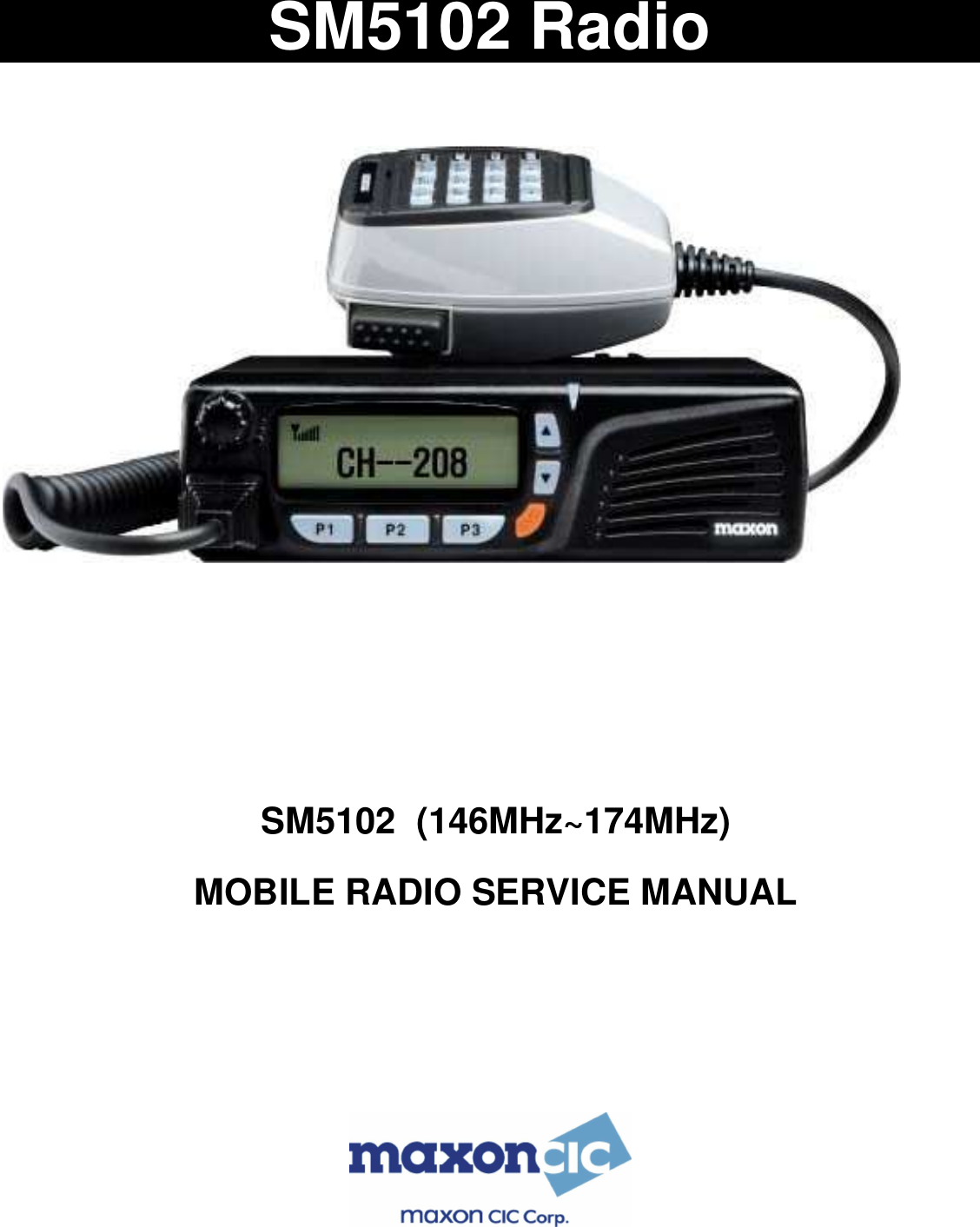
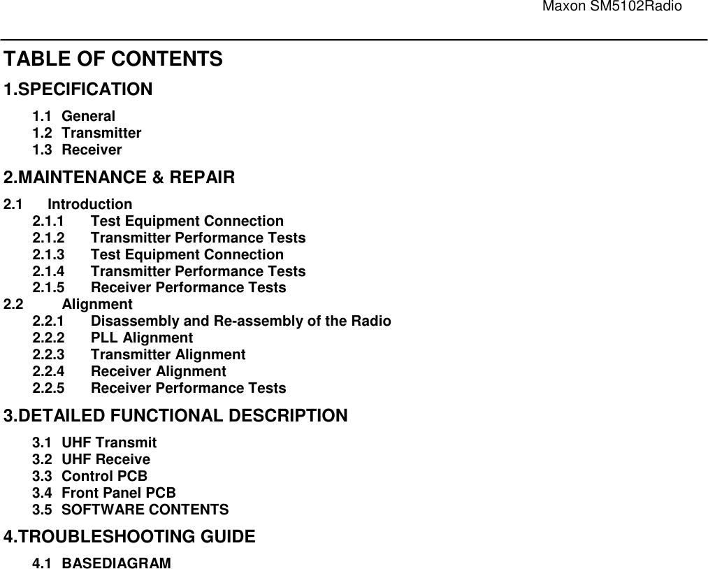
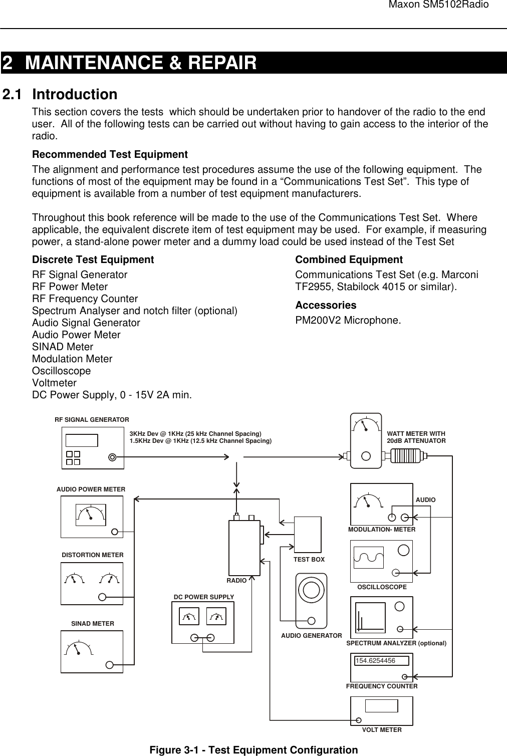
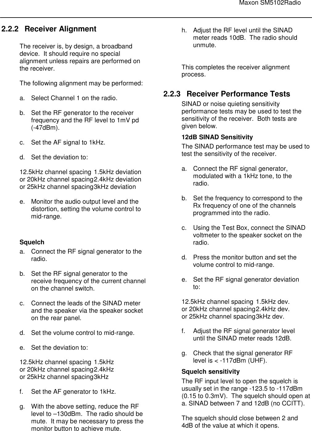
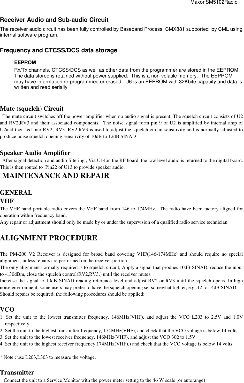
![Maxon SM5102Radio 3. BASIC Operation ■ Function keys There will be six push-buttons on the face of the SM5102; Up, Down, P1, P2, P3 and Emergency. below are the default programming settings. ■ Up button/ Down key - This button will allow the operator to scroll up/down through the available channel. A press-and-release of this button will increase/decrease the channel number. A press-and-hold will scroll through the succeeding channel num. -Push to select a transmit code channel after pushing [Two Tone code Channel select] -Push to select a DTMF channel after pushing [DTMF Code Channel Select] -Push to select a SMS channel after pushing [ SMS Code Channel Select] ■ Programmable function keys - The following functions can be assigned to [P1],[P2],[P3] programmable function keys. [Power key] - Push to toggle the transmit Output power between High and Low - Each channel can be programmed via the PC programmer and KEY to a high-power output, 50 Watts, and a low-power output, 5 Watt. [Light Key] - Push to toggle the auto mode or Light off mode. - AUTO Mode/OFF Mode is Selectable using Light Key. In case of Auto Mode, as pressed the key, the light is bright during the 5 s. [Monitor Key] - By pressing one of the option buttons programmed to be the Monitor button, the user shall defeat the programmed squelch operation and un-mute the speaker on the selected channel. [Lock Key] - This function can disable all keys except PTT, Emergency Key. [Scan Key] - Push to start and cancel scanning operation. [Public address Key] - Located under Programmable key, user selectable on or off. When selected and external speaker is attached the radio will output voice audio over the external speaker. [Two Tone Key] - Push and toggle the radio enable or disable Two Tone mode [SMS Key] - Push to enter the SMS code channel selection mode. - Then set the desired channel using [ UP/DOWN] - And then Push to transmit the SMS code in the SMS code selection mode . [1200/2400 bps Key] - Push and toggle the SMS baud rate 1200 bps or 2400 bps. [DTMF Key] - Push to enter the DTMF code channel selection mode. - Then set the desired channel using [UP/DOWN] - And then Push to transmit the DTMF code in the DTMF code selection mode . [GROUP Key] - Push to enter the group selection mode. - Then set the desired group using [UP/DOWN] - And then Push [GROUP ] to select the group number.](https://usermanual.wiki/Maxon-CIC/SM5102/User-Guide-1156289-Page-20.png)
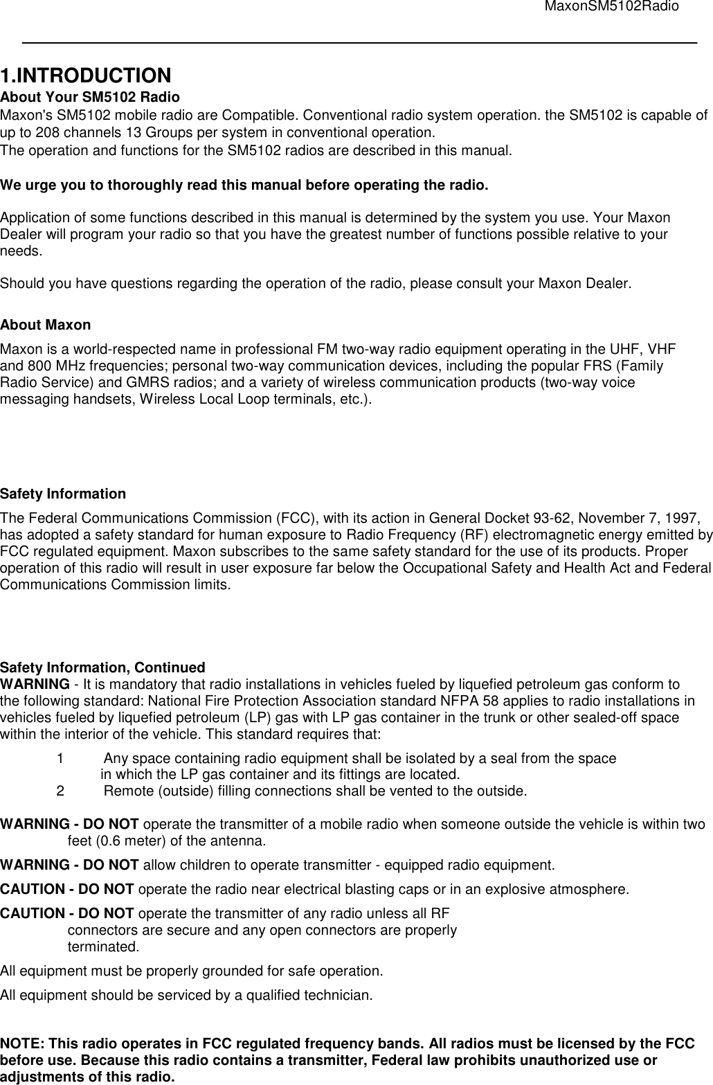
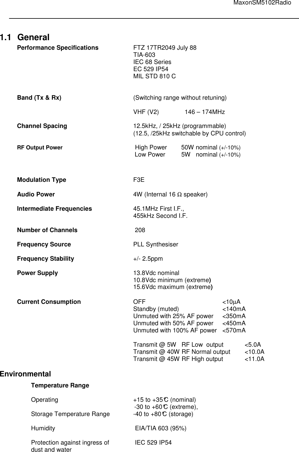
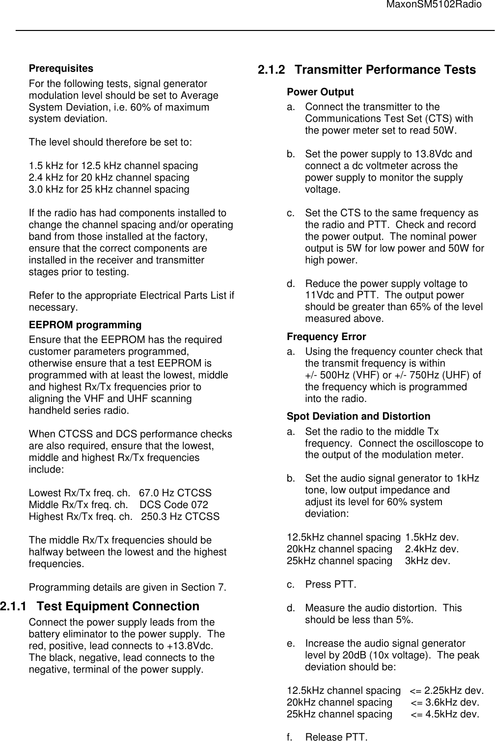
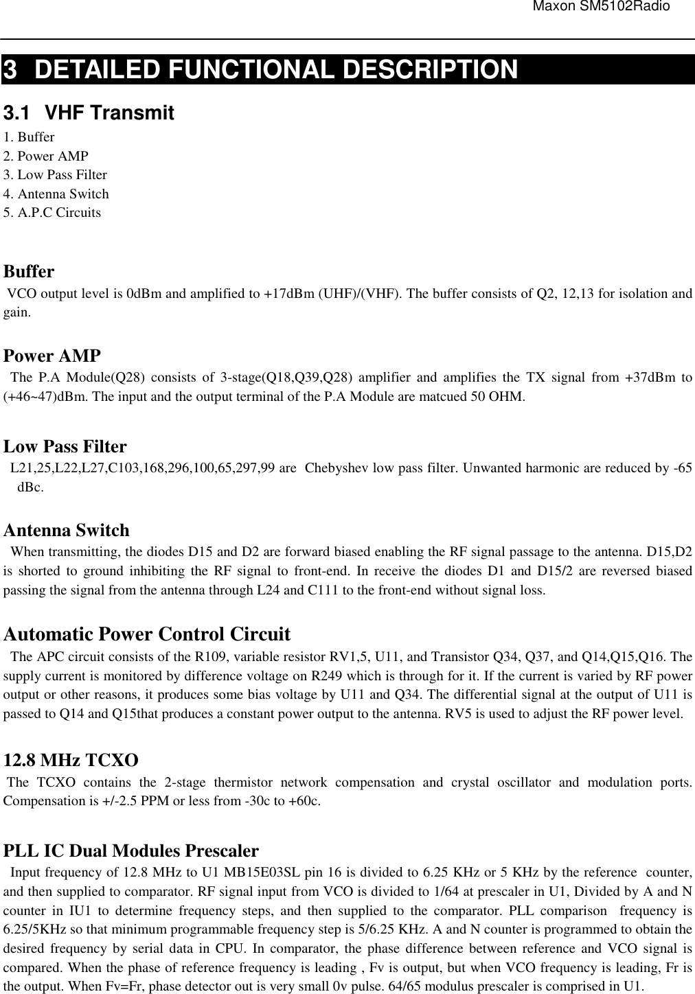
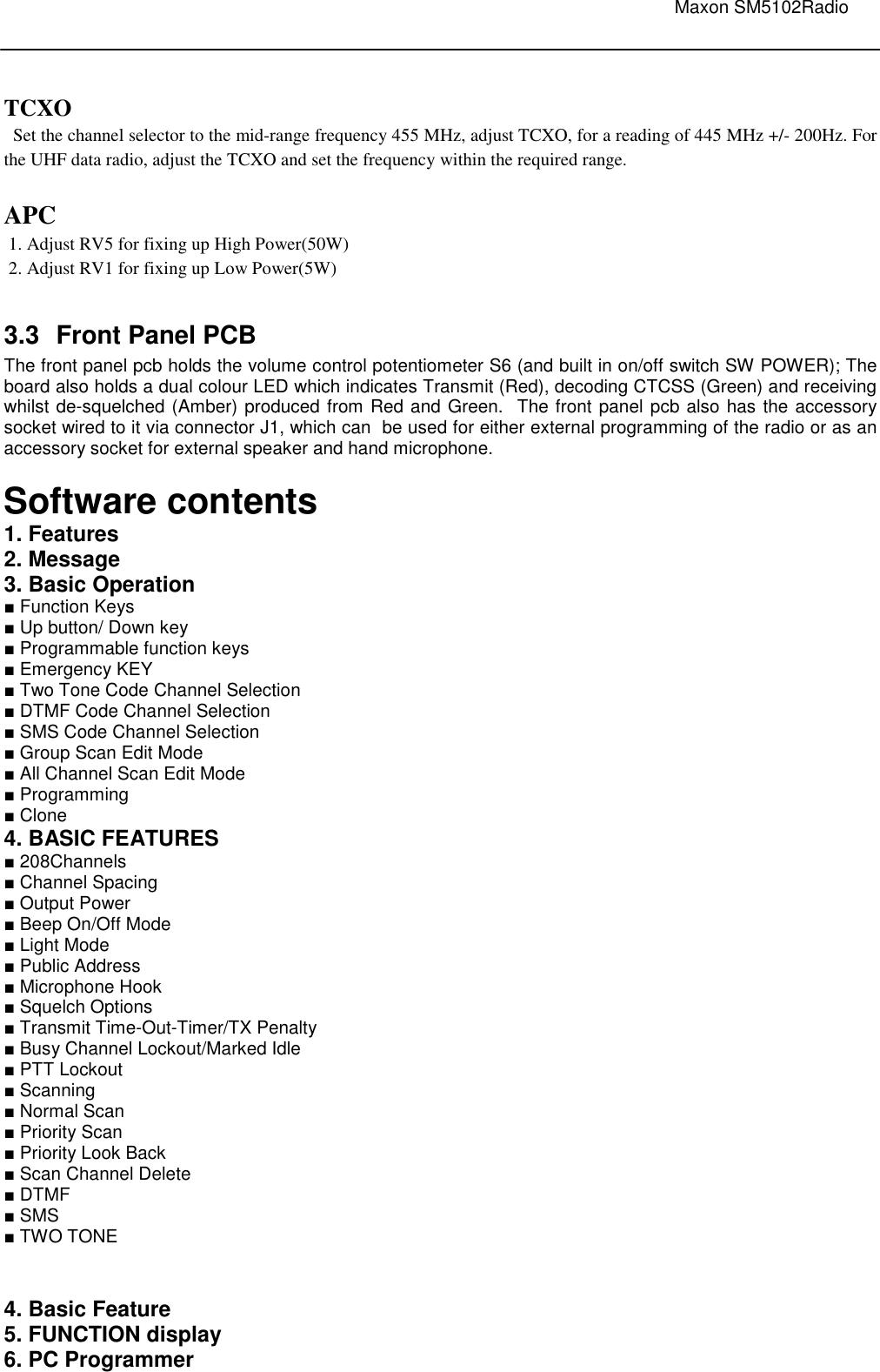
![MaxonSM5102Radio ■ Emergency KEY – When emergency button is pushed, an emergency signal is automatically transmitted for the specified time period. This is where the DTMF tone to be transmitted as the Emergency Call can be entered. After the emergency call, the transceiver performs transmission and reception alternately with the following conditions: - Transmits the microphone signals - Receives the signal and emits audio When Press the PTT, the function is cancelled. ■ Two Tone Code Channel Selection If the transceiver has [Two Tone] assigned to it, the automatic Two Tone transmission/reception function is available. To enable/disable Two Tone, Push the [Two Tone] key assigned by two tone function. This function key is toggled. ■ DTMF Code Channel Selection If the transceiver has [DTMF] assigned to it, the automatic DTMF transmission function is available. Up to 9 DTMF channels are available: To Select DTMF code Channel: - Push [ DTMF ] – a DTMF Code channel appears - Push [UP] or [DOWN] to select the desired DTMF Code channel. - Push [ DTMF ] to transmit the DTMF Code in selected DTMF channel. ■ SMS Code Channel Selection If the transceiver has [SMS] assigned to it, the automatic SMS transmission function is available. Up to 9 SMS channels are available: To select SMS code Channel - Push [ SMS ] – a SMS Code channel appears - Push [UP] or [DOWN] to select the desired SMS Code channel. - Push [ SMS ] to transmit the SMS Code in selected SMS channel. To change the baud rate: - Push [1200/2400 bps] ■ SCAN Edit Mode - You can edit your pre-programmed Group Scan List by adding or deleting scan list from the Group Scan List. To activate scan list editing, press and hold the P1 button on the front of the radio and turn volume on the radio. Upon entering the scan list edit function, the LCD displays the “Scan Edit ” message. To exit the scan list edit function, turn volume off the radio. 1. Select the Scan Group Each Scan Group would be displayed as “xx_nnn”. xx means group, and nnn means Channel. To activate scan list editing for selected group, press the P1 button. You can change the Scan Group Number by up or down button. 2. Adding or Deleting to Scan List If each channel is in the ‘Scan Editable List’, Channel Number would display Scan Icon, . To add or delete each channel to Scan Editable List, use P2 button. ■ Priority SCAN Channel Edit Priority Channel can be setup by PC programmer. Priority Scan List is also editable by the radio. It is called ‘Priority Channel Edit Mode’. If turn on the radio with pressing P2 Button, the radio enters Priority Channel Edit Mode. In the Priority Edit Mode, the LCD displays the “PscanEdit” message. 1.Select the Priority Group Each Scan Group dispalys “xx_nnn”. ‘xx’ means the current Group and ‘nnn’ means channel. To activate P scan list editing for selected Priority group, press the P1 button. You can change the Priority Group Number by up or down button.](https://usermanual.wiki/Maxon-CIC/SM5102/User-Guide-1156289-Page-21.png)
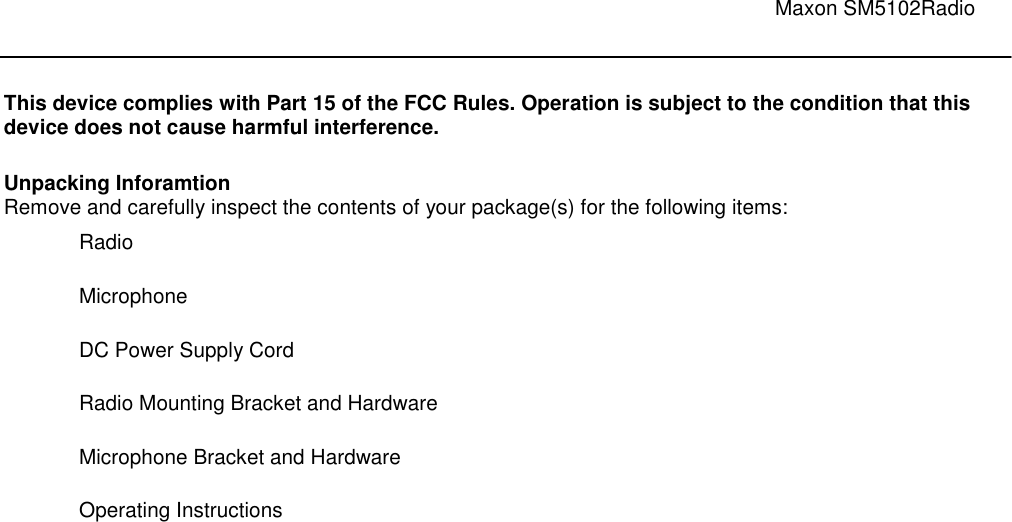
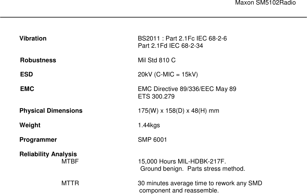
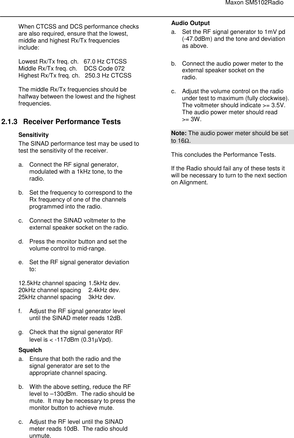
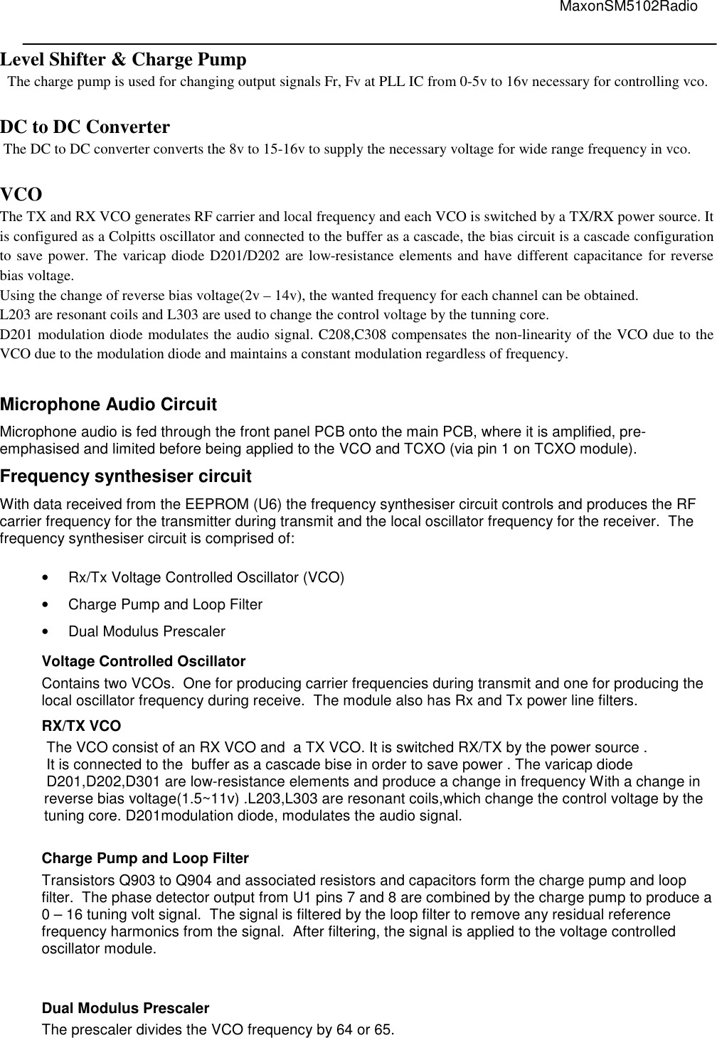
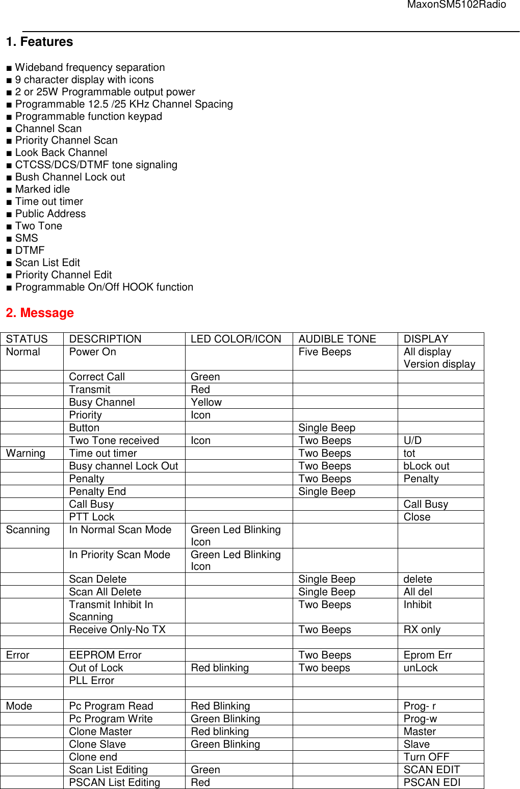
![Maxon SM5102Radio ■ Normal Scan Any number of channels shall be entered into the scan list. This will be equal to or less than the number of programmed channels. The LED shall flash green if programmed to. The flashing green LED will stop when ‘CARRIER’, or ‘CARRIER AND CORRECT TONE’. During scan delay, the LED shall remain clear. When Scan Delay expires and Scan Speed resumes, the LED shall also resume flashing green. ■ Priority Scan A priority channel can be programmed at the initial radio set-up stage. The priority channel will be part of the list of channels that make up the scan list. The priority channel when used with other scanned channels will operate as follows: P1→S1→P1→S2→P1→S3→P1→S4→P1, etc. ■ Priority Look Back Scan One channel can be programmed by the dealer to be the Priority channel, which will enable ‘Look-back’. This mode of operation can be used outside of the normal scanning mode. Pressing the Scan button shall activate Priority Look-back. The Priority Look-back causes the radio to periodically ‘Look-back’ to the priority channel for the presence of a carrier regardless of the channel that the user may be on. The frequency that the radio will ‘Look-back’ to the priority channel can be programmed between 1 to 7 seconds in 1-second increments. When carrier, or carrier and tone, are removed, the radio will revert back to the previously selected channel. ■ Transmitting during Scanning The radio shall be set to behave in a number of ways when the PTT is pressed during Scan. - Priority Scan TX – The radio can be set to transmit on the channel on which activity has been detected -OR- transmit on the priority channel if scanning is still active. - Priority Only TX – If scanning, or listening to an active channel, and the PTT bar is pressed the radio will only transmit on the priority channel. No transmissions shall be allowed to scanned calls. If transmission is attempted a warning tone will be sounded. - Rx only, No TX – No transmissions allowed during scanning. If transmission is attempted a warning tone will be sounded. - Normal Scan TX – Radio will only transmit on a stopped channel i.e. to return a call. Attempting to transmit during scanning will cause a warning alert. ■ Scan Channel Delete Pressing the ‘Monitor’ key, (when in scan mode and stopped on the channel) shall temporarily delete the channel from the scan list. This shall remove that channel from the scan list until the channel is changed or the radio’s power is reset. When power is restored or the scan list channel position is selected again, the originally programmed scan list shall be activated. ■ DTMF 1. Receiving an DTMF - When an DTMF is received DTMF data is displayed - When the received DTMF includes more than 8 characters, “►” appear. Push any button to return to the standby condition. 2. Transmitting an DTMF - 9 DTMF memory channels are available and the messages can be edited via PC Programming and ACC-703. 2.1 DTMF Transmission 2.1.1 Using call memory by PC Programming ○1 Push [DTMF]to enter the DTMF code memory channel selection mode. Up to 9 DTMF channels are available: ○2 Push [ DTMF ] – a DTMF Code channel appears ○3 Push [UP] or [DOWN] to select the desired DTMF Code channel. ○4 Push [ DTMF ] to transmit the DTMF Code in selected DTMF channel. 2.1.2 Direct code entry with ACC-703 2.1.2.1 Manual dial Operation ○1 . while in the standby condition, push [STR] 1 times, to enter the DTMF mode. - display ”DTMF”](https://usermanual.wiki/Maxon-CIC/SM5102/User-Guide-1156289-Page-24.png)
![MaxonSM5102Radio ○2 Push the appropriate [0]-[9], A,B,C,D,*,# to enter the desired character. ○3 Push the CLR Key. Number or character will be deleted at last Number or character. ○4 Push and hold the CLR key. All messages will be deleted. the radio enter the standby mode. ○5 Push the RCL key. Press the number key. DTMF message which is stored number is displayed at LCD. ○6 Push the RCL Key. Press the #,* key to removed the displayed data from the LCD. the radio enter the standby mode. ○7 Push and hold the RCL Key. the radio is changed with Number mode and Alphabet mode. ○8 Push and hold the STR Key to blink the cursor. Push [*] to move the cursor to left. Push[#] to move the cursor to the right ○9 Push the STR Key in the edit mode. Press the number key. DTMF message is stored -display[STORE Num] ○10 Push the SND key to transmitter the DTMF data. 2.1.2.2 Clearing a Dialed Number When a number has been accidentally entered during auto dial a press and release of the CLR key will delete an individual number. A press and hold of the CLR key will clear the entire dialed number. 2.1.2.3 To Store a Number in Memory Dial the desired number. Entered number will show in the radio display. Press and release the STR key. Press and release any number 0 – 9 to store the number, * and # cannot be used for storing a number. STORed will show in the radio display indicating the number has been stored in memory under that key. 2.1.2.4 To Recall a Stored number from Memory Press and release the RCL key. Press and release the number key from which a number has been stored. Press SND to dial the recalled number. If a number has been accidentally recalled repeat steps 1. and 2. until the proper number has been recalled. 2.1.2.5 Clearing a Stored Number Press and release the RCL key. Press and release the number key from which a number has been stored. The stored number will show in the radio display. Press and hold the CLR key to remove the stored number. A new number can now be entered and stored in that location. 2.1.2.5 Decode action ● Stun – this shall prevent any transmission from the radio and will also mute the speaker. ● Revive – this shall re-activate the radio. ● Covert On – a valid address shall cause the radio to cycle between Tx mode and Rx mode. The time periods spent in Tx and Rx modes shall be programmed into the addressee radio, however, it will be the Base Station or DTMF Sender, that remotely turns this feature ON or OFF. ● Covert Off – this shall remotely turn the radios’ covert mode off, i.e. the radio will return back to passive receive mode. ■ SMS 1. Receiving an SMS - When an SMS is received : the SMS data is displayed - When the received SMS includes more than 8 characters, “►” appear. Push any button to return to the standby condition. 2. Received message selection -The Radio memorizes the received messaged for record. UP to 9 messages for SMS, of 40 character SMS can be memorized. The oldest message is erased when the 10th message is received. However, once the radio is powered off, all messages are cleared. ○1 .Push [SMS] : displays “RECORD” ○2 .Push[SMS] : Displays message memory ○3 .Push [ UP] or [DOWN] to select the desired message - When selecting the SMS that includes more than 8 characters, “►” appear.](https://usermanual.wiki/Maxon-CIC/SM5102/User-Guide-1156289-Page-25.png)
![Maxon SM5102Radio ○4 . Push and hold the ACC-703 [STR ] button to enter the message scroll mode. ○5 . Push the ACC-703 [#],[ * ] button to scroll the messages. ○6 . Push [SMS] : again to return to the standby condition 3. Transmitting an SMS - 9 SMS memory channels are available and the messages can be edited via PC Programming and ACC-703. 3.1 SMS Transmission 3.1.1 Using SMS memory by PC Programming ○1 Push [SMS] to enter the SMS code memory channel selection mode. Up to 9 SMS channels are available: ○2 Push [UP] or [DOWN] to select the desired SMS Code channel. ○3 Push [ SMS ] to transmit the SMS Code in selected SMS channel. 3.1.2 Direct code entry with ACC-703 ○1 During standby condition, push [STR] 3 times, to enter the SMS mode. - Display ”SMS” ○2 Push the appropriate digit key,[0],[9], to enter the desired character. ○3 Push the CLR Key. Number or character will be deleted at cursor. ○4 Push and hold the CLR key. All messages will be deleted. the radio enter the standby mode. ○5 Push the RCL key. Press the number key. SMS message which is stored number is displayed at LCD. ○6 Push the RCL Key. Press the #,* key to removed the displayed data from the LCD. the radio enter the standby mode. ○7 Push and hold the RCL Key. the radio is changed with Number mode and Alphabet mode. ○8 Push and hold the # key to work the space key. ○9 Push and hold the STR Key to blink the cursor. Push [*] to move the cursor to left. Push [#] to move the cursor to the right ○10 Push the STR Key in the edit mode. Press the number key. SMS message is stored -Display[STORE Num] ○11 Push the SND key to transmitter the SMS data. ■ TWO TONE 1. Two Tone Option 1.1 Two Tone Enable/Disable - Enable : can receive/transmit two tone. - Disable : cannot receive/transmit two tone 1.2 Two Tone Decoding Alert - Enable : It rings alert sound when the radio detects two tone correctly and if no action, alert sound every 3seconds.(but first time, alert sound in 10 seconds one time) If you do any action after detecting two tone(ex: push a key or change volume level etc…), then stop the alert sound. - Disable : No alert sound 1.3 Every Time Two Tone Detect - Enable : Check the Two Tone whether correct or not whenever receive a Two Tone signal. - Disable : Check the Two Tone one time only when receive a Two Tone signal firstly, From Next time, don’t check the Two Tone. If you change to another channel, Radio will repeat above. 2. Two Tone En/Decoding You can set Individual, Group, Super Group 3 kinds of Two Tones. 2.1 Lead In Time : The time until transmit two tone after pressing PTT key. 2.2 Tone Time : The length of Tone A or Tone B 2.3 Gap Time : The length between tone A and tone B. 2.4 Two Tone Type : You can set a desire Two Tone type with PC Programmer at each channel - Decoding : It must be correct all tone A, Gap, tone B time and frequency to open speaker. - Encoding : Transmit Two Tone setting frequency (tone A, gap, tone B) after PTT.](https://usermanual.wiki/Maxon-CIC/SM5102/User-Guide-1156289-Page-26.png)
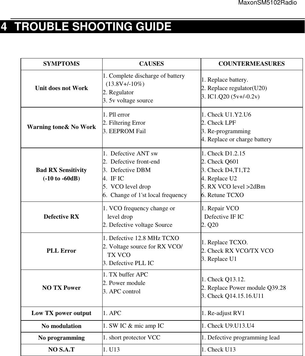
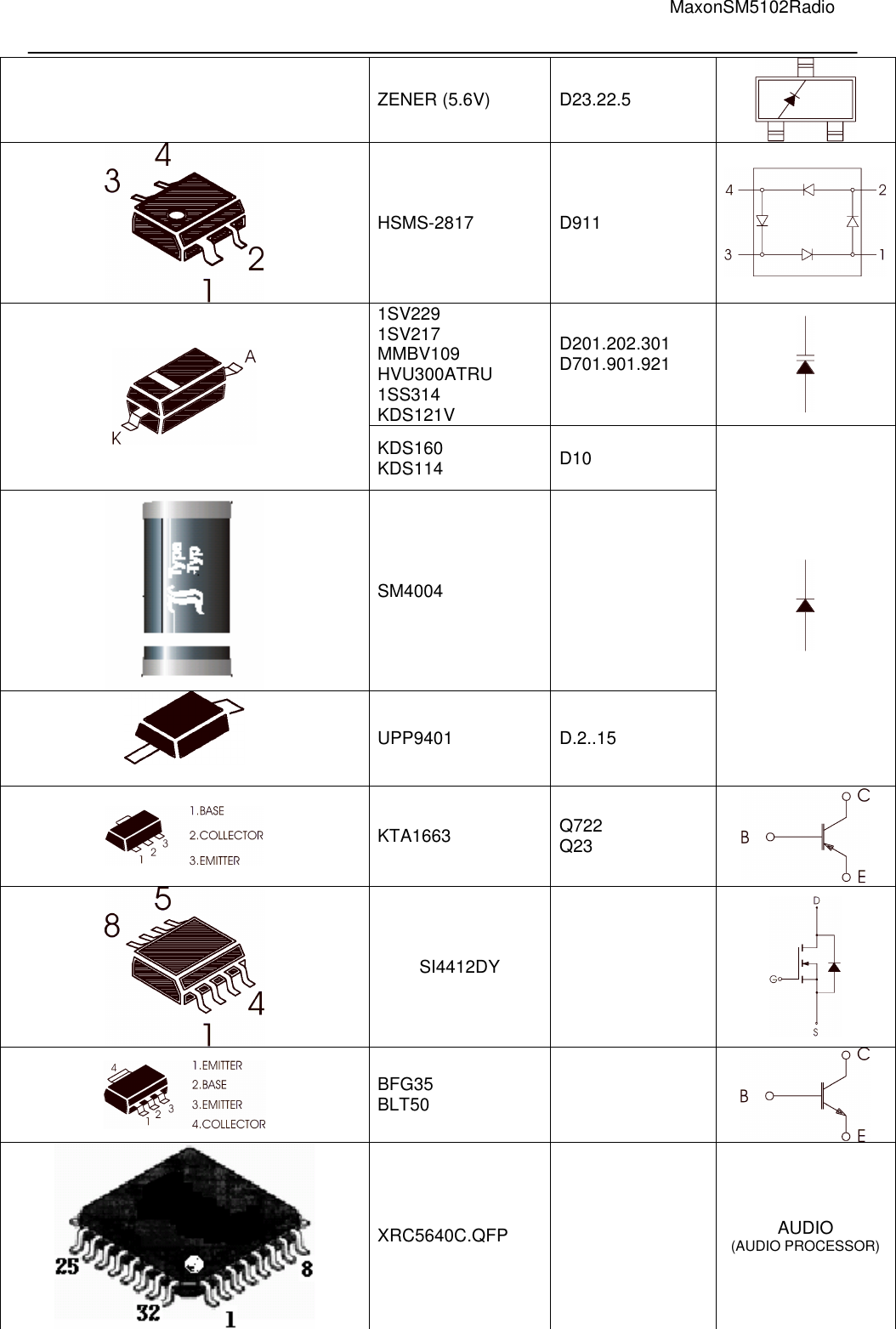
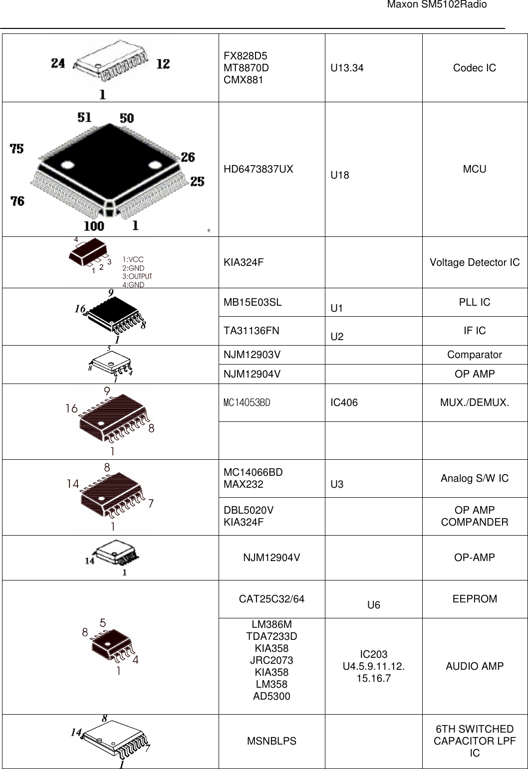
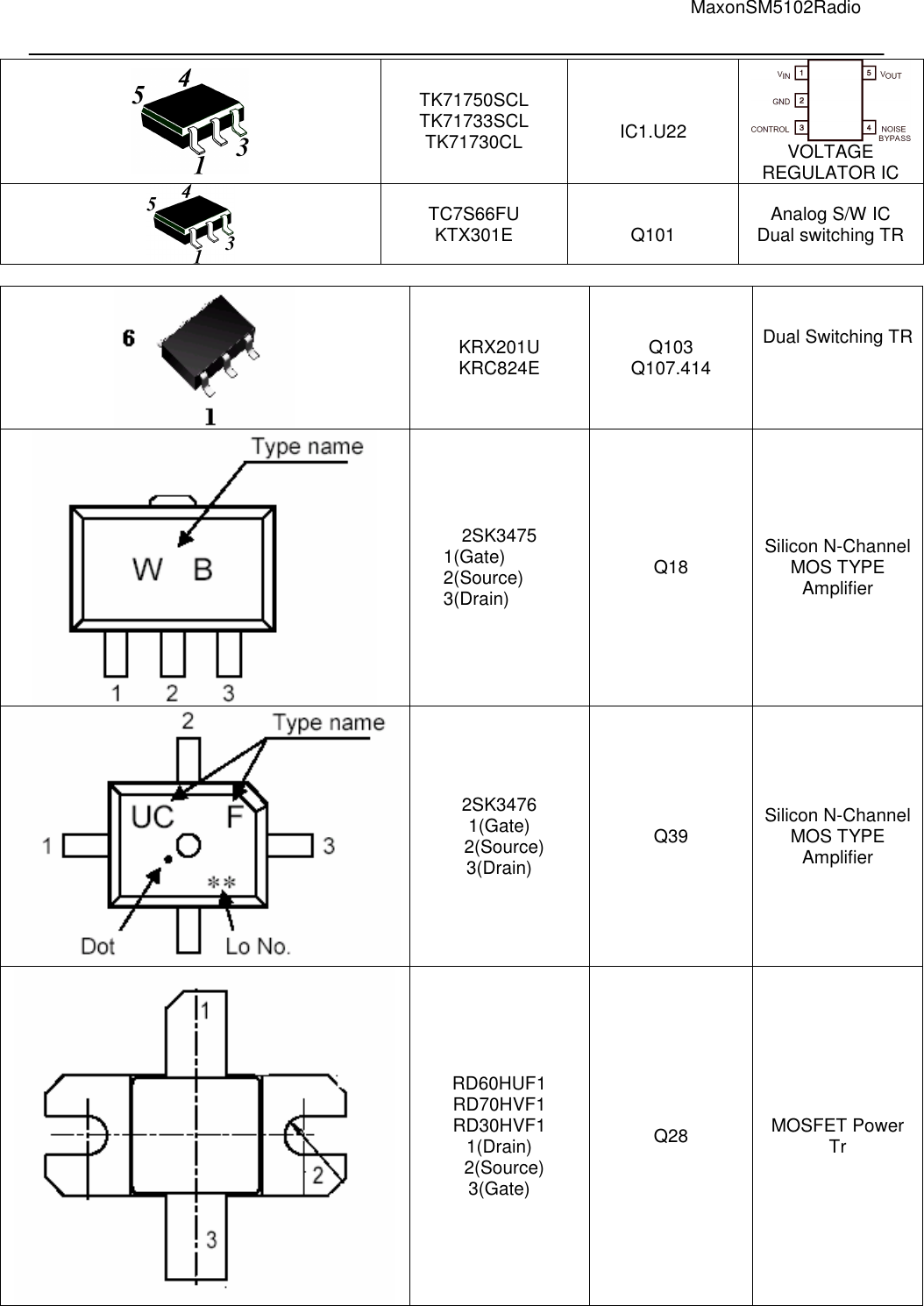
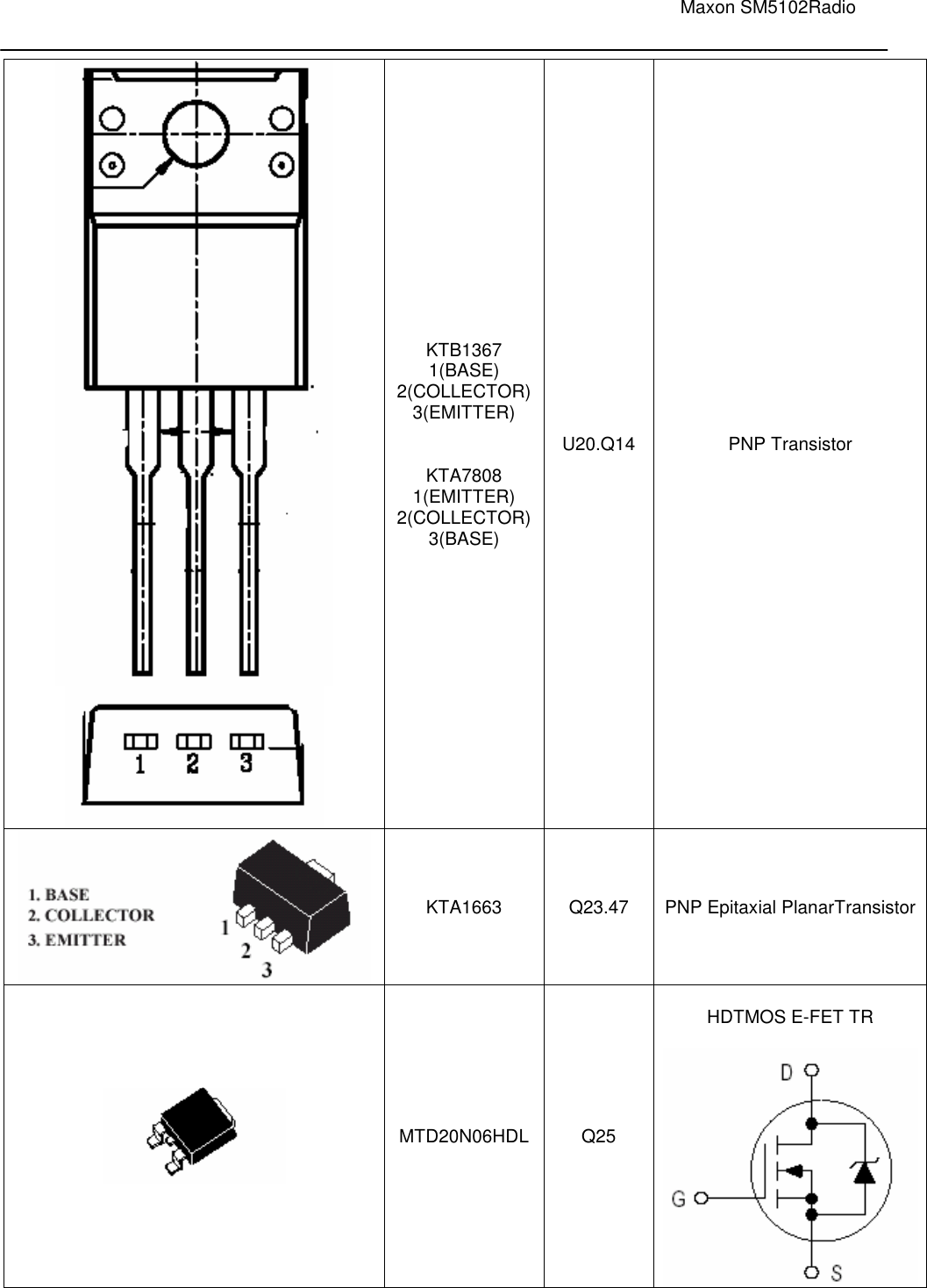
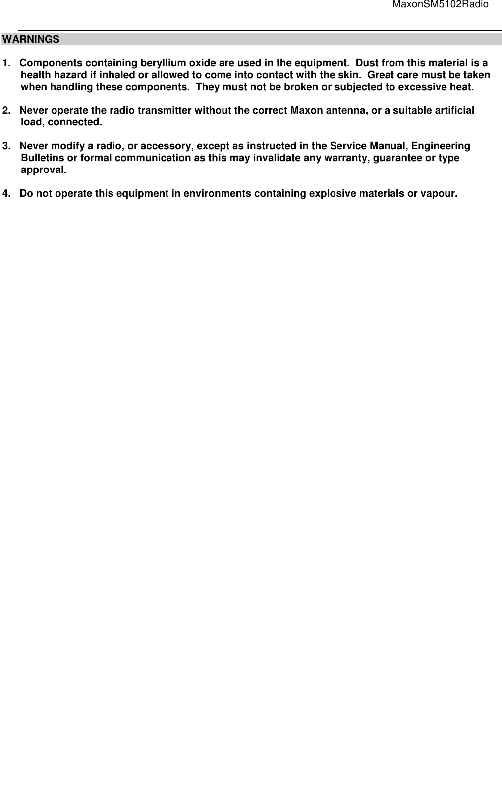
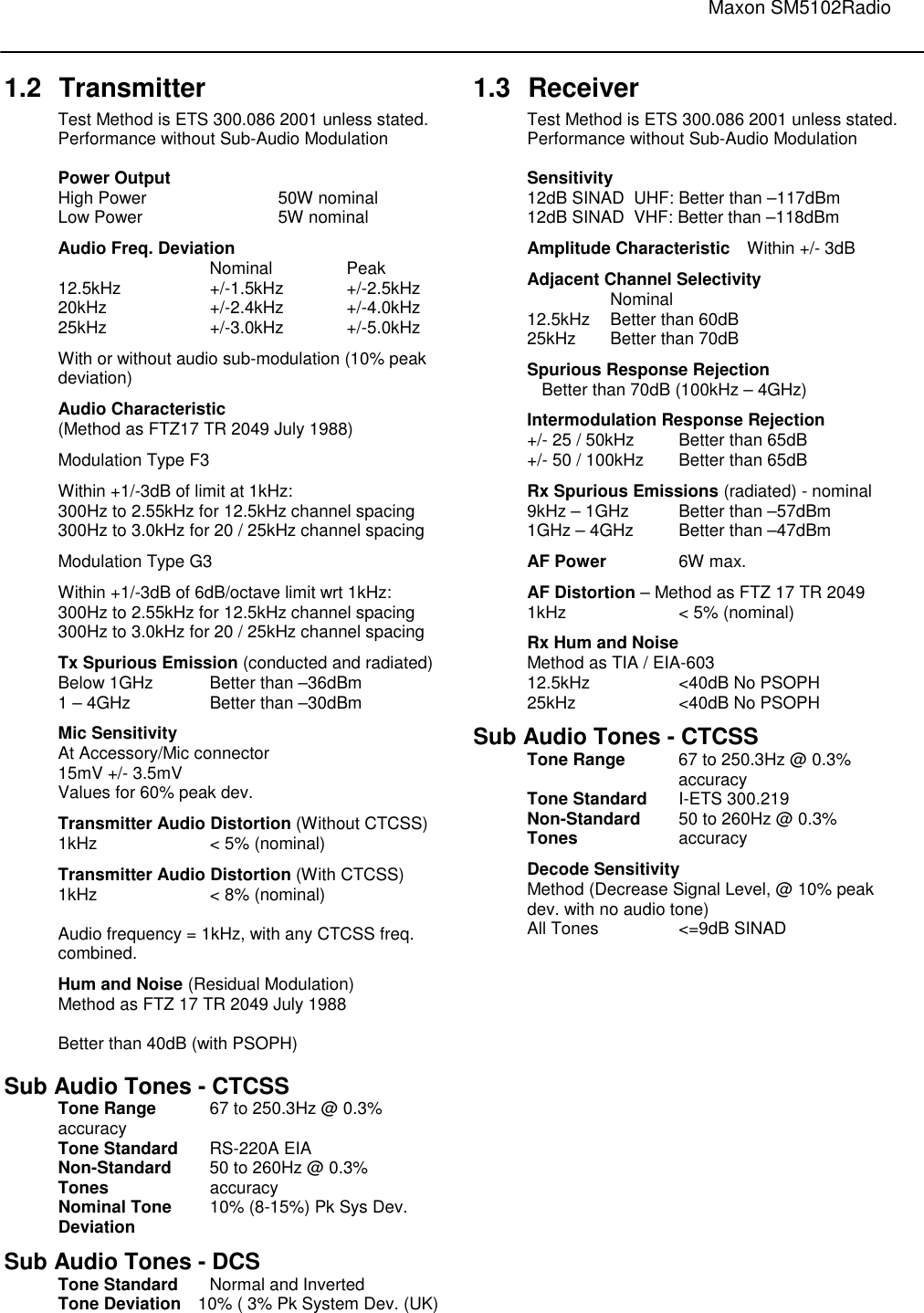
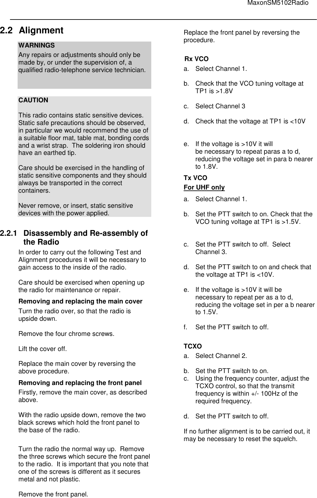
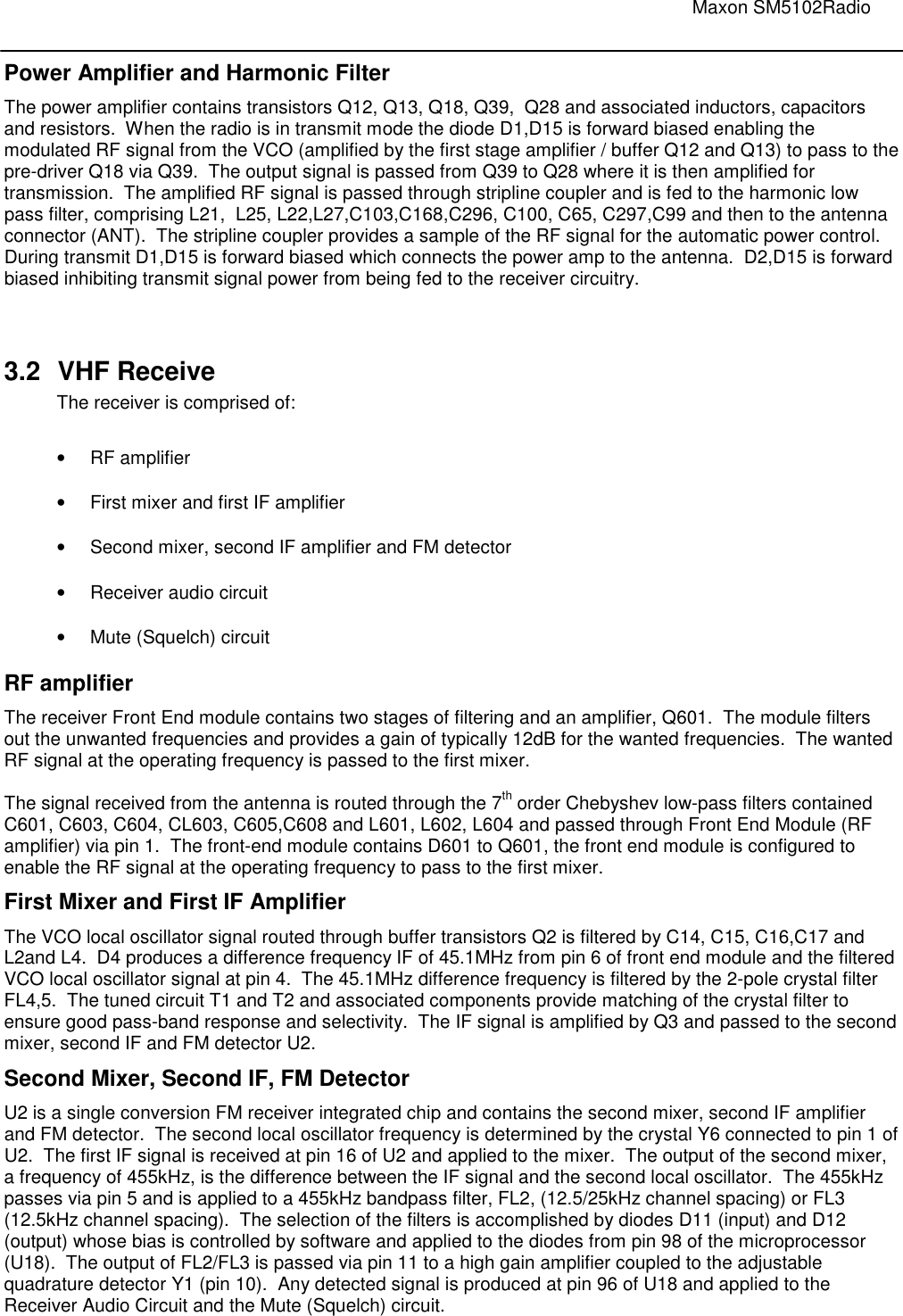
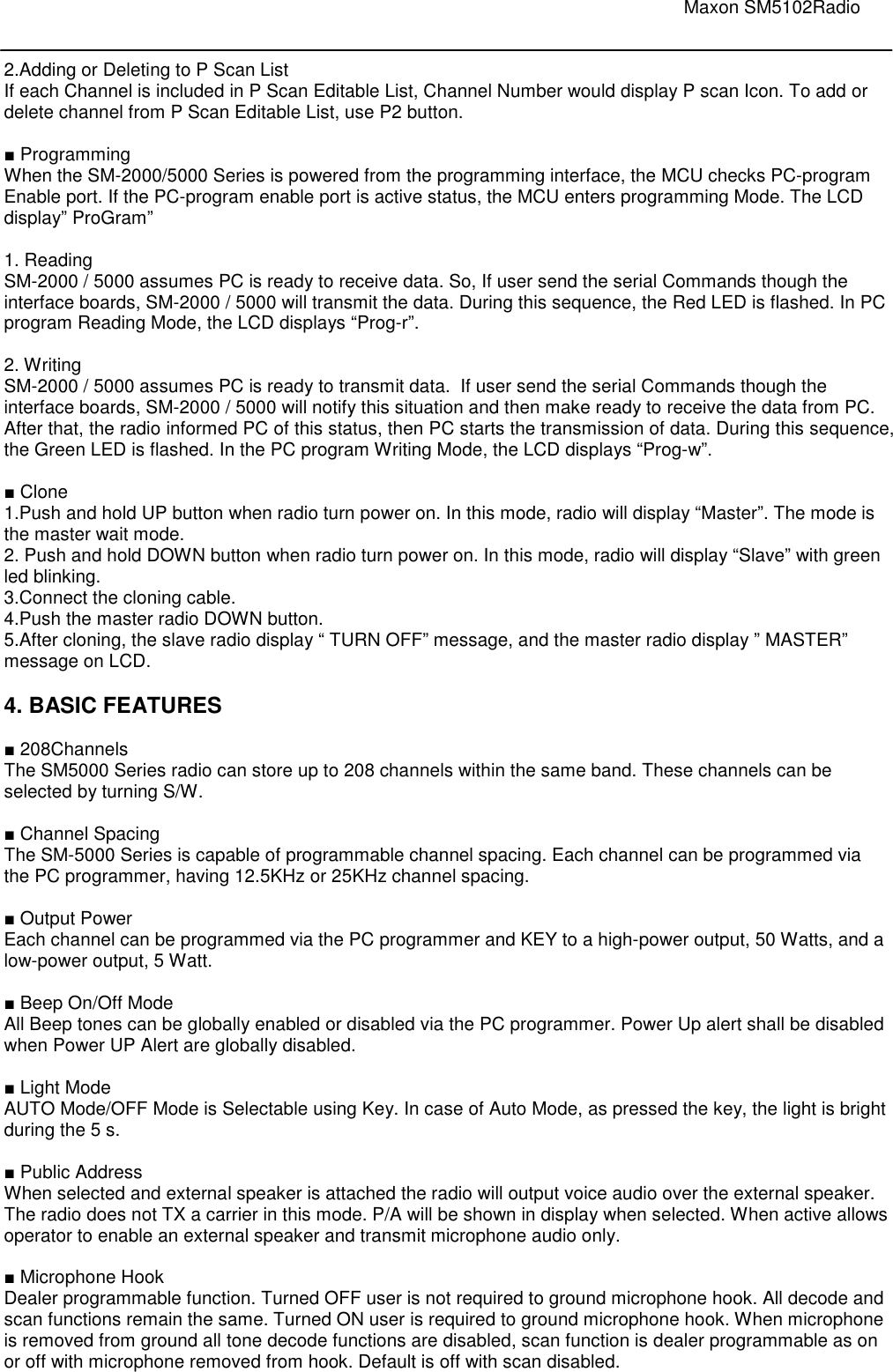
![Maxon SM5102Radio BASE DIAGRAM BASE DIAGRAM MANUFACTURER’S PART NUMBER REFERENCE NO. SYMBOL KTC5084 KTC3880 Q202.203.302.303 AT-41532 Q601 KTC4075 Q41.42.43.44.46 KTA2014 Q602.641.643 PBR951 Q12 BFR92A .Q3.2.13 KTC3875S Q901.904.7 KTA1504S Q902.903 KRC104S (ND) KRC101SNA KRC404V Q5.6.8.10.16 .19.22.26.27.30.32 34.37.38.48 KRA104S (PD) KRA304V] KRA310V KRA226 Q9 KRC110S (NK) KRA110S (PK) KRA101S KRA104 Q1.4.11.29.31.33. 36.40.204.304 BASE DIAGRAM MANUFACTURER’S PART NUMBER REFERENCE NO. SYMBOL KDS181 (A3) KDS184 D11.12.8.11.12. 17 KDS193 (F3) D20 KDS226 (C3) KDS122V KDS120V .D601 D201.202 D16.18](https://usermanual.wiki/Maxon-CIC/SM5102/User-Guide-1156289-Page-30.png)