Maxon CIC SM5102 Two way VHF LMR User Manual SM5102 MANUAL
Maxon CIC Corp. Two way VHF LMR SM5102 MANUAL
User Manual
SM5102 Radio
SM5102 (146MHz~174MHz)
MOBILE RADIO SERVICE MANUAL

MaxonSM5102Radio
1.INTRODUCTION
About Your SM5102 Radio
Maxon's SM5102 mobile radio are Compatible. Conventional radio system operation. the SM5102 is capable of
up to 208 channels 13 Groups per system in conventional operation.
The operation and functions for the SM5102 radios are described in this manual.
We urge you to thoroughly read this manual before operating the radio.
Application of some functions described in this manual is determined by the system you use. Your Maxon
Dealer will program your radio so that you have the greatest number of functions possible relative to your
needs.
Should you have questions regarding the operation of the radio, please consult your Maxon Dealer.
About Maxon
Maxon is a world-respected name in professional FM two-way radio equipment operating in the UHF, VHF
and 800 MHz frequencies; personal two-way communication devices, including the popular FRS (Family
Radio Service) and GMRS radios; and a variety of wireless communication products (two-way voice
messaging handsets, Wireless Local Loop terminals, etc.).
Safety Information
The Federal Communications Commission (FCC), with its action in General Docket 93-62, November 7, 1997,
has adopted a safety standard for human exposure to Radio Frequency (RF) electromagnetic energy emitted by
FCC regulated equipment. Maxon subscribes to the same safety standard for the use of its products. Proper
operation of this radio will result in user exposure far below the Occupational Safety and Health Act and Federal
Communications Commission limits.
Safety Information, Continued
WARNING - It is mandatory that radio installations in vehicles fueled by liquefied petroleum gas conform to
the following standard: National Fire Protection Association standard NFPA 58 applies to radio installations in
vehicles fueled by liquefied petroleum (LP) gas with LP gas container in the trunk or other sealed-off space
within the interior of the vehicle. This standard requires that:
1 Any space containing radio equipment shall be isolated by a seal from the space
in which the LP gas container and its fittings are located.
2 Remote (outside) filling connections shall be vented to the outside.
WARNING - DO NOT operate the transmitter of a mobile radio when someone outside the vehicle is within two
feet (0.6 meter) of the antenna.
WARNING - DO NOT allow children to operate transmitter - equipped radio equipment.
CAUTION - DO NOT operate the radio near electrical blasting caps or in an explosive atmosphere.
CAUTION - DO NOT operate the transmitter of any radio unless all RF
connectors are secure and any open connectors are properly
terminated.
All equipment must be properly grounded for safe operation.
All equipment should be serviced by a qualified technician.
NOTE: This radio operates in FCC regulated frequency bands. All radios must be licensed by the FCC
before use. Because this radio contains a transmitter, Federal law prohibits unauthorized use or
adjustments of this radio.

Maxon SM5102Radio
This device complies with Part 15 of the FCC Rules. Operation is subject to the condition that this
device does not cause harmful interference.
Unpacking Inforamtion
Remove and carefully inspect the contents of your package(s) for the following items:
Radio
Microphone
DC Power Supply Cord
Radio Mounting Bracket and Hardware
Microphone Bracket and Hardware
Operating Instructions

MaxonSM5102Radio
WARNINGS
1. Components containing beryllium oxide are used in the equipment. Dust from this material is a
health hazard if inhaled or allowed to come into contact with the skin. Great care must be taken
when handling these components. They must not be broken or subjected to excessive heat.
2. Never operate the radio transmitter without the correct Maxon antenna, or a suitable artificial
load, connected.
3. Never modify a radio, or accessory, except as instructed in the Service Manual, Engineering
Bulletins or formal communication as this may invalidate any warranty, guarantee or type
approval.
4. Do not operate this equipment in environments containing explosive materials or vapour.

Maxon SM5102Radio
TABLE OF CONTENTS
1.SPECIFICATION
1.1 General
1.2 Transmitter
1.3 Receiver
2.MAINTENANCE & REPAIR
2.1 Introduction
2.1.1 Test Equipment Connection
2.1.2 Transmitter Performance Tests
2.1.3 Test Equipment Connection
2.1.4 Transmitter Performance Tests
2.1.5 Receiver Performance Tests
2.2 Alignment
2.2.1 Disassembly and Re-assembly of the Radio
2.2.2 PLL Alignment
2.2.3 Transmitter Alignment
2.2.4 Receiver Alignment
2.2.5 Receiver Performance Tests
3.DETAILED FUNCTIONAL DESCRIPTION
3.1 UHF Transmit
3.2 UHF Receive
3.3 Control PCB
3.4 Front Panel PCB
3.5 SOFTWARE CONTENTS
4.TROUBLESHOOTING GUIDE
4.1 BASEDIAGRAM

MaxonSM5102Radio
1.1 General
Performance Specifications FTZ 17TR2049 July 88
TIA-603
IEC 68 Series
EC 529 IP54
MIL STD 810 C
Band (Tx & Rx) (Switching range without retuning)
VHF (V2) 146 – 174MHz
Channel Spacing 12.5kHz, / 25kHz (programmable)
(12.5, /25kHz switchable by CPU control)
RF Output Power
High Power 50W nominal
(+/-10%)
Low Power 5W nominal
(+/-10%)
Modulation Type F3E
Audio Power 4W (Internal 16 Ω speaker)
Intermediate Frequencies 45.1MHz First I.F.,
455kHz Second I.F.
Number of Channels 208
Frequency Source PLL Synthesiser
Frequency Stability +/- 2.5ppm
Power Supply 13.8Vdc nominal
10.8Vdc minimum (extreme)
15.6Vdc maximum (extreme)
Current Consumption OFF <10µA
Standby (muted) <140mA
Unmuted with 25% AF power <350mA
Unmuted with 50% AF power <450mA
Unmuted with 100% AF power <570mA
Transmit @ 5W RF Low output <5.0A
Transmit @ 40W RF Normal output <10.0A
Transmit @ 45W RF High output <11.0A
Environmental
Temperature Range
Operating +15 to +35°C (nominal)
-30 to +60°C (extreme),
Storage Temperature Range -40 to +80°C (storage)
Humidity EIA/TIA 603 (95%)
Protection against ingress of IEC 529 IP54
dust and water

Maxon SM5102Radio
Vibration BS2011 : Part 2.1Fc IEC 68-2-6
Part 2.1Fd IEC 68-2-34
Robustness Mil Std 810 C
ESD 20kV (C-MIC = 15kV)
EMC EMC Directive 89/336/EEC May 89
ETS 300.279
Physical Dimensions 175(W) x 158(D) x 48(H) mm
Weight 1.44kgs
Programmer SMP 6001
Reliability Analysis
MTBF 15,000 Hours MIL-HDBK-217F.
Ground benign. Parts stress method.
MTTR 30 minutes average time to rework any SMD
component and reassemble.

Maxon SM5102Radio
1.2 Transmitter
Test Method is ETS 300.086 2001 unless stated.
Performance without Sub-Audio Modulation
Power Output
High Power 50W nominal
Low Power 5W nominal
Audio Freq. Deviation
Nominal Peak
12.5kHz +/-1.5kHz +/-2.5kHz
20kHz +/-2.4kHz +/-4.0kHz
25kHz +/-3.0kHz +/-5.0kHz
With or without audio sub-modulation (10% peak
deviation)
Audio Characteristic
(Method as FTZ17 TR 2049 July 1988)
Modulation Type F3
Within +1/-3dB of limit at 1kHz:
300Hz to 2.55kHz for 12.5kHz channel spacing
300Hz to 3.0kHz for 20 / 25kHz channel spacing
Modulation Type G3
Within +1/-3dB of 6dB/octave limit wrt 1kHz:
300Hz to 2.55kHz for 12.5kHz channel spacing
300Hz to 3.0kHz for 20 / 25kHz channel spacing
Tx Spurious Emission (conducted and radiated)
Below 1GHz Better than –36dBm
1 – 4GHz Better than –30dBm
Mic Sensitivity
At Accessory/Mic connector
15mV +/- 3.5mV
Values for 60% peak dev.
Transmitter Audio Distortion (Without CTCSS)
1kHz < 5% (nominal)
Transmitter Audio Distortion (With CTCSS)
1kHz < 8% (nominal)
Audio frequency = 1kHz, with any CTCSS freq.
combined.
Hum and Noise (Residual Modulation)
Method as FTZ 17 TR 2049 July 1988
Better than 40dB (with PSOPH)
Sub Audio Tones - CTCSS
Tone Range 67 to 250.3Hz @ 0.3%
accuracy
Tone Standard RS-220A EIA
Non-Standard 50 to 260Hz @ 0.3%
Tones accuracy
Nominal Tone 10% (8-15%) Pk Sys Dev.
Deviation
Sub Audio Tones - DCS
Tone Standard Normal and Inverted
Tone Deviation 10% ( 3% Pk System Dev. (UK)
1.3 Receiver
Test Method is ETS 300.086 2001 unless stated.
Performance without Sub-Audio Modulation
Sensitivity
12dB SINAD UHF: Better than –117dBm
12dB SINAD VHF: Better than –118dBm
Amplitude Characteristic Within +/- 3dB
Adjacent Channel Selectivity
Nominal
12.5kHz Better than 60dB
25kHz Better than 70dB
Spurious Response Rejection
Better than 70dB (100kHz – 4GHz)
Intermodulation Response Rejection
+/- 25 / 50kHz Better than 65dB
+/- 50 / 100kHz Better than 65dB
Rx Spurious Emissions (radiated) - nominal
9kHz – 1GHz Better than –57dBm
1GHz – 4GHz Better than –47dBm
AF Power 6W max.
AF Distortion – Method as FTZ 17 TR 2049
1kHz < 5% (nominal)
Rx Hum and Noise
Method as TIA / EIA-603
12.5kHz <40dB No PSOPH
25kHz <40dB No PSOPH
Sub Audio Tones - CTCSS
Tone Range 67 to 250.3Hz @ 0.3%
accuracy
Tone Standard I-ETS 300.219
Non-Standard 50 to 260Hz @ 0.3%
Tones accuracy
Decode Sensitivity
Method (Decrease Signal Level, @ 10% peak
dev. with no audio tone)
All Tones <=9dB SINAD
Maxon SM5102Radio
2 MAINTENANCE & REPAIR
2.1 Introduction
This section covers the tests which should be undertaken prior to handover of the radio to the end
user. All of the following tests can be carried out without having to gain access to the interior of the
radio.
Recommended Test Equipment
The alignment and performance test procedures assume the use of the following equipment. The
functions of most of the equipment may be found in a “Communications Test Set”. This type of
equipment is available from a number of test equipment manufacturers.
Throughout this book reference will be made to the use of the Communications Test Set. Where
applicable, the equivalent discrete item of test equipment may be used. For example, if measuring
power, a stand-alone power meter and a dummy load could be used instead of the Test Set
Discrete Test Equipment
RF Signal Generator
RF Power Meter
RF Frequency Counter
Spectrum Analyser and notch filter (optional)
Audio Signal Generator
Audio Power Meter
SINAD Meter
Modulation Meter
Oscilloscope
Voltmeter
DC Power Supply, 0 - 15V 2A min.
Combined Equipment
Communications Test Set (e.g. Marconi
TF2955, Stabilock 4015 or similar).
Accessories
PM200V2 Microphone.
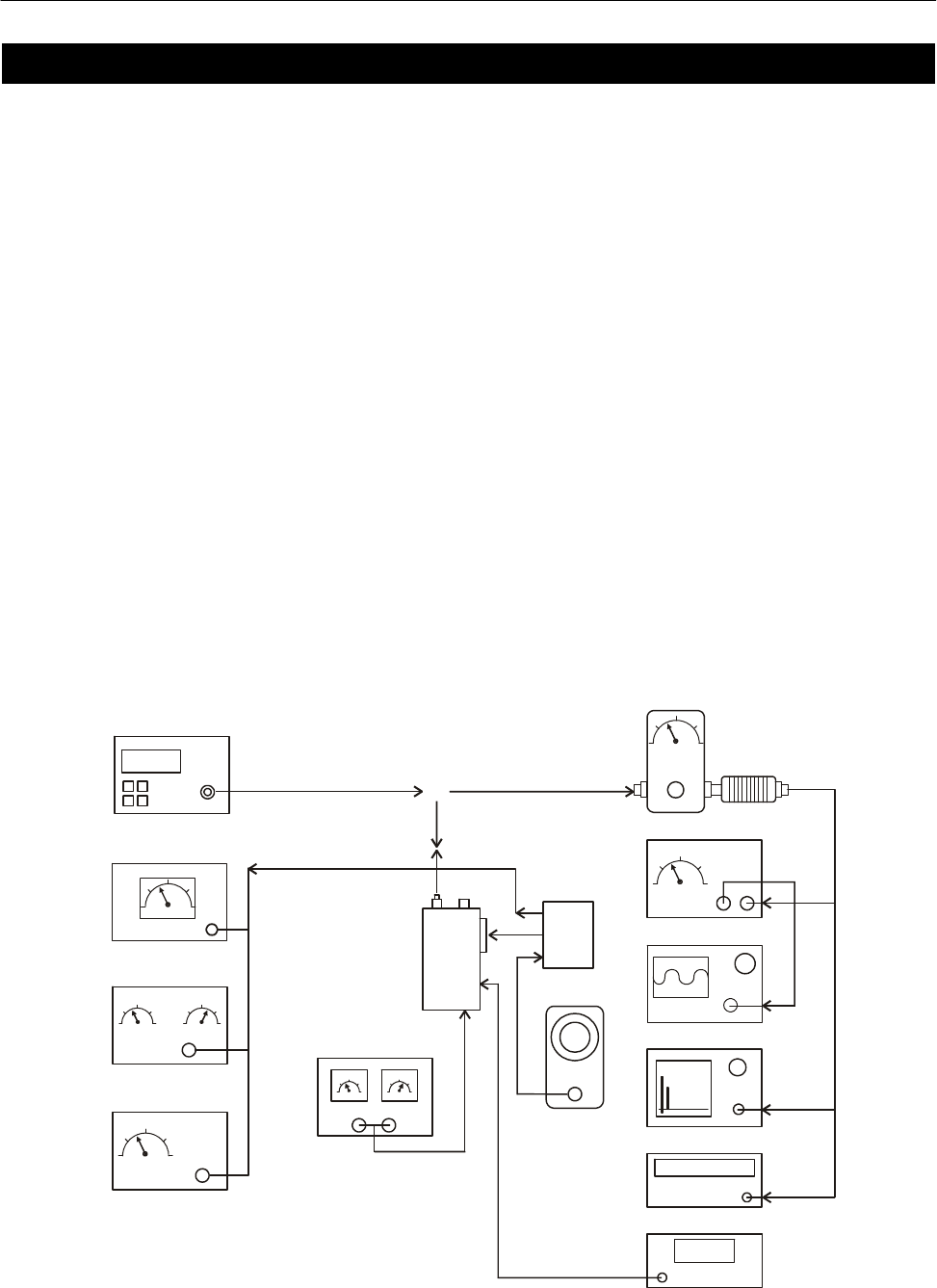
154.6254456
WATT METER WITH
20dB ATTENUATOR
AUDIO
MODULATION- METER
AUDIO GENERATOR
DC POWER SUPPLY
RADIO OSCILLOSCOPE
SPECTRUM ANALYZER (optional)
FREQUENCY COUNTER
VOLT METER
AUDIO POWER METER
SINAD METER
DISTORTION METER
RF SIGNAL GENERATOR
3KHz Dev @ 1KHz (25 kHz Channel Spacing)
1.5KHz Dev @ 1KHz (12.5 kHz Channel Spacing)
TEST BOX
Figure 3-1 - Test Equipment Configuration

MaxonSM5102Radio
Prerequisites
For the following tests, signal generator
modulation level should be set to Average
System Deviation, i.e. 60% of maximum
system deviation.
The level should therefore be set to:
1.5 kHz for 12.5 kHz channel spacing
2.4 kHz for 20 kHz channel spacing
3.0 kHz for 25 kHz channel spacing
If the radio has had components installed to
change the channel spacing and/or operating
band from those installed at the factory,
ensure that the correct components are
installed in the receiver and transmitter
stages prior to testing.
Refer to the appropriate Electrical Parts List if
necessary.
EEPROM programming
Ensure that the EEPROM has the required
customer parameters programmed,
otherwise ensure that a test EEPROM is
programmed with at least the lowest, middle
and highest Rx/Tx frequencies prior to
aligning the VHF and UHF scanning
handheld series radio.
When CTCSS and DCS performance checks
are also required, ensure that the lowest,
middle and highest Rx/Tx frequencies
include:
Lowest Rx/Tx freq. ch. 67.0 Hz CTCSS
Middle Rx/Tx freq. ch. DCS Code 072
Highest Rx/Tx freq. ch. 250.3 Hz CTCSS
The middle Rx/Tx frequencies should be
halfway between the lowest and the highest
frequencies.
Programming details are given in Section 7.
2.1.1 Test Equipment Connection
Connect the power supply leads from the
battery eliminator to the power supply. The
red, positive, lead connects to +13.8Vdc.
The black, negative, lead connects to the
negative, terminal of the power supply.
2.1.2 Transmitter Performance Tests
Power Output
a. Connect the transmitter to the
Communications Test Set (CTS) with
the power meter set to read 50W.
b. Set the power supply to 13.8Vdc and
connect a dc voltmeter across the
power supply to monitor the supply
voltage.
c. Set the CTS to the same frequency as
the radio and PTT. Check and record
the power output. The nominal power
output is 5W for low power and 50W for
high power.
d. Reduce the power supply voltage to
11Vdc and PTT. The output power
should be greater than 65% of the level
measured above.
Frequency Error
a. Using the frequency counter check that
the transmit frequency is within
+/- 500Hz (VHF) or +/- 750Hz (UHF) of
the frequency which is programmed
into the radio.
Spot Deviation and Distortion
a. Set the radio to the middle Tx
frequency. Connect the oscilloscope to
the output of the modulation meter.
b. Set the audio signal generator to 1kHz
tone, low output impedance and
adjust its level for 60% system
deviation:
12.5kHz channel spacing 1.5kHz dev.
20kHz channel spacing 2.4kHz dev.
25kHz channel spacing 3kHz dev.
c. Press PTT.
d. Measure the audio distortion. This
should be less than 5%.
e. Increase the audio signal generator
level by 20dB (10x voltage). The peak
deviation should be:
12.5kHz channel spacing <= 2.25kHz dev.
20kHz channel spacing <= 3.6kHz dev.
25kHz channel spacing <= 4.5kHz dev.
f. Release PTT.

Maxon SM5102Radio
When CTCSS and DCS performance checks
are also required, ensure that the lowest,
middle and highest Rx/Tx frequencies
include:
Lowest Rx/Tx freq. ch. 67.0 Hz CTCSS
Middle Rx/Tx freq. ch. DCS Code 072
Highest Rx/Tx freq. ch. 250.3 Hz CTCSS
The middle Rx/Tx frequencies should be
halfway between the lowest and the highest
frequencies.
2.1.3 Receiver Performance Tests
Sensitivity
The SINAD performance test may be used to
test the sensitivity of the receiver.
a. Connect the RF signal generator,
modulated with a 1kHz tone, to the
radio.
b. Set the frequency to correspond to the
Rx frequency of one of the channels
programmed into the radio.
c. Connect the SINAD voltmeter to the
external speaker socket on the radio.
d. Press the monitor button and set the
volume control to mid-range.
e. Set the RF signal generator deviation
to:
12.5kHz channel spacing 1.5kHz dev.
20kHz channel spacing 2.4kHz dev.
25kHz channel spacing 3kHz dev.
f. Adjust the RF signal generator level
until the SINAD meter reads 12dB.
g. Check that the signal generator RF
level is < -117dBm (0.31µVpd).
Squelch
a. Ensure that both the radio and the
signal generator are set to the
appropriate channel spacing.
b. With the above setting, reduce the RF
level to –130dBm. The radio should be
mute. It may be necessary to press the
monitor button to achieve mute.
c. Adjust the RF level until the SINAD
meter reads 10dB. The radio should
unmute.
Audio Output
a. Set the RF signal generator to 1mV pd
(-47.0dBm) and the tone and deviation
as above.
b. Connect the audio power meter to the
external speaker socket on the
radio.
c. Adjust the volume control on the radio
under test to maximum (fully clockwise).
The voltmeter should indicate >= 3.5V.
The audio power meter should read
>= 3W.
Note: The audio power meter should be set
to 16Ω.
This concludes the Performance Tests.
If the Radio should fail any of these tests it
will be necessary to turn to the next section
on Alignment.

MaxonSM5102Radio
2.2 Alignment
WARNINGS
Any repairs or adjustments should only be
made by, or under the supervision of, a
qualified radio-telephone service technician.
CAUTION
This radio contains static sensitive devices.
Static safe precautions should be observed,
in particular we would recommend the use of
a suitable floor mat, table mat, bonding cords
and a wrist strap. The soldering iron should
have an earthed tip.
Care should be exercised in the handling of
static sensitive components and they should
always be transported in the correct
containers.
Never remove, or insert, static sensitive
devices with the power applied.
2.2.1 Disassembly and Re-assembly of
the Radio
In order to carry out the following Test and
Alignment procedures it will be necessary to
gain access to the inside of the radio.
Care should be exercised when opening up
the radio for maintenance or repair.
Removing and replacing the main cover
Turn the radio over, so that the radio is
upside down.
Remove the four chrome screws.
Lift the cover off.
Replace the main cover by reversing the
above procedure.
Removing and replacing the front panel
Firstly, remove the main cover, as described
above.
With the radio upside down, remove the two
black screws which hold the front panel to
the base of the radio.
Turn the radio the normal way up. Remove
the three screws which secure the front panel
to the radio. It is important that you note that
one of the screws is different as it secures
metal and not plastic.
Remove the front panel.
Replace the front panel by reversing the
procedure.
Rx VCO
a. Select Channel 1.
b. Check that the VCO tuning voltage at
TP1 is >1.8V
c. Select Channel 3
d. Check that the voltage at TP1 is <10V
e. If the voltage is >10V it will
be necessary to repeat paras a to d,
reducing the voltage set in para b nearer
to 1.8V.
Tx VCO
For UHF only
a. Select Channel 1.
b. Set the PTT switch to on. Check that the
VCO tuning voltage at TP1 is >1.5V.
c. Set the PTT switch to off. Select
Channel 3.
d. Set the PTT switch to on and check that
the voltage at TP1 is <10V.
e. If the voltage is >10V it will be
necessary to repeat per as a to d,
reducing the voltage set in per a b nearer
to 1.5V.
f. Set the PTT switch to off.
TCXO
a. Select Channel 2.
b. Set the PTT switch to on.
c. Using the frequency counter, adjust the
TCXO control, so that the transmit
frequency is within +/- 100Hz of the
required frequency.
d. Set the PTT switch to off.
If no further alignment is to be carried out, it
may be necessary to reset the squelch.

Maxon SM5102Radio
2.2.2 Receiver Alignment
The receiver is, by design, a broadband
device. It should require no special
alignment unless repairs are performed on
the receiver.
The following alignment may be performed:
a. Select Channel 1 on the radio.
b. Set the RF generator to the receiver
frequency and the RF level to 1mV pd
(-47dBm).
c. Set the AF signal to 1kHz.
d. Set the deviation to:
12.5kHz channel spacing 1.5kHz deviation
or 20kHz channel spacing 2.4kHz deviation
or 25kHz channel spacing 3kHz deviation
e. Monitor the audio output level and the
distortion, setting the volume control to
mid-range.
Squelch
a. Connect the RF signal generator to the
radio.
b. Set the RF signal generator to the
receive frequency of the current channel
on the channel switch.
c. Connect the leads of the SINAD meter
and the speaker via the speaker socket
on the rear panel.
d. Set the volume control to mid-range.
e. Set the deviation to:
12.5kHz channel spacing 1.5kHz
or 20kHz channel spacing 2.4kHz
or 25kHz channel spacing 3kHz
f. Set the AF generator to 1kHz.
g. With the above setting, reduce the RF
level to –130dBm. The radio should be
mute. It may be necessary to press the
monitor button to achieve mute.
h. Adjust the RF level until the SINAD
meter reads 10dB. The radio should
unmute.
This completes the receiver alignment
process.
2.2.3 Receiver Performance Tests
SINAD or noise quieting sensitivity
performance tests may be used to test the
sensitivity of the receiver. Both tests are
given below.
12dB SINAD Sensitivity
The SINAD performance test may be used to
test the sensitivity of the receiver.
a. Connect the RF signal generator,
modulated with a 1kHz tone, to the
radio.
b. Set the frequency to correspond to the
Rx frequency of one of the channels
programmed into the radio.
c. Using the Test Box, connect the SINAD
voltmeter to the speaker socket on the
radio.
d. Press the monitor button and set the
volume control to mid-range.
e. Set the RF signal generator deviation
to:
12.5kHz channel spacing 1.5kHz dev.
or 20kHz channel spacing 2.4kHz dev.
or 25kHz channel spacing 3kHz dev.
f. Adjust the RF signal generator level
until the SINAD meter reads 12dB.
g. Check that the signal generator RF
level is < -117dBm (UHF).
Squelch sensitivity
The RF input level to open the squelch is
usually set in the range -123.5 to -117dBm
(0.15 to 0.3mV). The squelch should open at
a. SINAD between 7 and 12dB (no CCITT).
The squelch should close between 2 and
4dB of the value at which it opens.

Maxon SM5102Radio
3 DETAILED FUNCTIONAL DESCRIPTION
3.1 VHF Transmit
1. Buffer
2. Power AMP
3. Low Pass Filter
4. Antenna Switch
5. A.P.C Circuits
Buffer
VCO output level is 0dBm and amplified to +17dBm (UHF)/(VHF). The buffer consists of Q2, 12,13 for isolation and
gain.
Power AMP
The P.A Module(Q28) consists of 3-stage(Q18,Q39,Q28) amplifier and amplifies the TX signal from +37dBm to
(+46~47)dBm. The input and the output terminal of the P.A Module are matcued 50 OHM.
Low Pass Filter
L21,25,L22,L27,C103,168,296,100,65,297,99 are Chebyshev low pass filter. Unwanted harmonic are reduced by -65
dBc.
Antenna Switch
When transmitting, the diodes D15 and D2 are forward biased enabling the RF signal passage to the antenna. D15,D2
is shorted to ground inhibiting the RF signal to front-end. In receive the diodes D1 and D15/2 are reversed biased
passing the signal from the antenna through L24 and C111 to the front-end without signal loss.
Automatic Power Control Circuit
The APC circuit consists of the R109, variable resistor RV1,5, U11, and Transistor Q34, Q37, and Q14,Q15,Q16. The
supply current is monitored by difference voltage on R249 which is through for it. If the current is varied by RF power
output or other reasons, it produces some bias voltage by U11 and Q34. The differential signal at the output of U11 is
passed to Q14 and Q15that produces a constant power output to the antenna. RV5 is used to adjust the RF power level.
12.8 MHz TCXO
The TCXO contains the 2-stage thermistor network compensation and crystal oscillator and modulation ports.
Compensation is +/-2.5 PPM or less from -30c to +60c.
PLL IC Dual Modules Prescaler
Input frequency of 12.8 MHz to U1 MB15E03SL pin 16 is divided to 6.25 KHz or 5 KHz by the reference counter,
and then supplied to comparator. RF signal input from VCO is divided to 1/64 at prescaler in U1, Divided by A and N
counter in IU1 to determine frequency steps, and then supplied to the comparator. PLL comparison frequency is
6.25/5KHz so that minimum programmable frequency step is 5/6.25 KHz. A and N counter is programmed to obtain the
desired frequency by serial data in CPU. In comparator, the phase difference between reference and VCO signal is
compared. When the phase of reference frequency is leading , Fv is output, but when VCO frequency is leading, Fr is
the output. When Fv=Fr, phase detector out is very small 0v pulse. 64/65 modulus prescaler is comprised in U1.

MaxonSM5102Radio
Level Shifter & Charge Pump
The charge pump is used for changing output signals Fr, Fv at PLL IC from 0-5v to 16v necessary for controlling vco.
DC to DC Converter
The DC to DC converter converts the 8v to 15-16v to supply the necessary voltage for wide range frequency in vco.
VCO
The TX and RX VCO generates RF carrier and local frequency and each VCO is switched by a TX/RX power source. It
is configured as a Colpitts oscillator and connected to the buffer as a cascade, the bias circuit is a cascade configuration
to save power. The varicap diode D201/D202 are low-resistance elements and have different capacitance for reverse
bias voltage.
Using the change of reverse bias voltage(2v – 14v), the wanted frequency for each channel can be obtained.
L203 are resonant coils and L303 are used to change the control voltage by the tunning core.
D201 modulation diode modulates the audio signal. C208,C308 compensates the non-linearity of the VCO due to the
VCO due to the modulation diode and maintains a constant modulation regardless of frequency.
Microphone Audio Circuit
Microphone audio is fed through the front panel PCB onto the main PCB, where it is amplified, pre-
emphasised and limited before being applied to the VCO and TCXO (via pin 1 on TCXO module).
Frequency synthesiser circuit
With data received from the EEPROM (U6) the frequency synthesiser circuit controls and produces the RF
carrier frequency for the transmitter during transmit and the local oscillator frequency for the receiver. The
frequency synthesiser circuit is comprised of:
• Rx/Tx Voltage Controlled Oscillator (VCO)
• Charge Pump and Loop Filter
• Dual Modulus Prescaler
Voltage Controlled Oscillator
Contains two VCOs. One for producing carrier frequencies during transmit and one for producing the
local oscillator frequency during receive. The module also has Rx and Tx power line filters.
RX/TX VCO
The VCO consist of an RX VCO and a TX VCO. It is switched RX/TX by the power source .
It is connected to the buffer as a cascade bise in order to save power . The varicap diode
D201,D202,D301 are low-resistance elements and produce a change in frequency With a change in
reverse bias voltage(1.5~11v) .L203,L303 are resonant coils,which change the control voltage by the
tuning core. D201modulation diode, modulates the audio signal.
Charge Pump and Loop Filter
Transistors Q903 to Q904 and associated resistors and capacitors form the charge pump and loop
filter. The phase detector output from U1 pins 7 and 8 are combined by the charge pump to produce a
0 – 16 tuning volt signal. The signal is filtered by the loop filter to remove any residual reference
frequency harmonics from the signal. After filtering, the signal is applied to the voltage controlled
oscillator module.
Dual Modulus Prescaler
The prescaler divides the VCO frequency by 64 or 65.

Maxon SM5102Radio
Power Amplifier and Harmonic Filter
The power amplifier contains transistors Q12, Q13, Q18, Q39, Q28 and associated inductors, capacitors
and resistors. When the radio is in transmit mode the diode D1,D15 is forward biased enabling the
modulated RF signal from the VCO (amplified by the first stage amplifier / buffer Q12 and Q13) to pass to the
pre-driver Q18 via Q39. The output signal is passed from Q39 to Q28 where it is then amplified for
transmission. The amplified RF signal is passed through stripline coupler and is fed to the harmonic low
pass filter, comprising L21, L25, L22,L27,C103,C168,C296, C100, C65, C297,C99 and then to the antenna
connector (ANT). The stripline coupler provides a sample of the RF signal for the automatic power control.
During transmit D1,D15 is forward biased which connects the power amp to the antenna. D2,D15 is forward
biased inhibiting transmit signal power from being fed to the receiver circuitry.
3.2 VHF Receive
The receiver is comprised of:
• RF amplifier
• First mixer and first IF amplifier
• Second mixer, second IF amplifier and FM detector
• Receiver audio circuit
• Mute (Squelch) circuit
RF amplifier
The receiver Front End module contains two stages of filtering and an amplifier, Q601. The module filters
out the unwanted frequencies and provides a gain of typically 12dB for the wanted frequencies. The wanted
RF signal at the operating frequency is passed to the first mixer.
The signal received from the antenna is routed through the 7
th
order Chebyshev low-pass filters contained
C601, C603, C604, CL603, C605,C608 and L601, L602, L604 and passed through Front End Module (RF
amplifier) via pin 1. The front-end module contains D601 to Q601, the front end module is configured to
enable the RF signal at the operating frequency to pass to the first mixer.
First Mixer and First IF Amplifier
The VCO local oscillator signal routed through buffer transistors Q2 is filtered by C14, C15, C16,C17 and
L2and L4. D4 produces a difference frequency IF of 45.1MHz from pin 6 of front end module and the filtered
VCO local oscillator signal at pin 4. The 45.1MHz difference frequency is filtered by the 2-pole crystal filter
FL4,5. The tuned circuit T1 and T2 and associated components provide matching of the crystal filter to
ensure good pass-band response and selectivity. The IF signal is amplified by Q3 and passed to the second
mixer, second IF and FM detector U2.
Second Mixer, Second IF, FM Detector
U2 is a single conversion FM receiver integrated chip and contains the second mixer, second IF amplifier
and FM detector. The second local oscillator frequency is determined by the crystal Y6 connected to pin 1 of
U2. The first IF signal is received at pin 16 of U2 and applied to the mixer. The output of the second mixer,
a frequency of 455kHz, is the difference between the IF signal and the second local oscillator. The 455kHz
passes via pin 5 and is applied to a 455kHz bandpass filter, FL2, (12.5/25kHz channel spacing) or FL3
(12.5kHz channel spacing). The selection of the filters is accomplished by diodes D11 (input) and D12
(output) whose bias is controlled by software and applied to the diodes from pin 98 of the microprocessor
(U18). The output of FL2/FL3 is passed via pin 11 to a high gain amplifier coupled to the adjustable
quadrature detector Y1 (pin 10). Any detected signal is produced at pin 96 of U18 and applied to the
Receiver Audio Circuit and the Mute (Squelch) circuit.

MaxonSM5102Radio
Receiver Audio and Sub-audio Circuit
The receiver audio circuit has been fully controlled by Baseband Process, CMX881 supported by CML using
internal software program.
Frequency and CTCSS/DCS data storage
EEPROM
Rx/Tx channels, CTCSS/DCS as well as other data from the programmer are stored in the EEPROM.
The data stored is retained without power supplied. This is a non-volatile memory. The EEPROM
may have information re-programmed or erased. U6 is an EEPROM with 32Kbite capacity and data is
written and read serially
Mute (squelch) Circuit
The mute circuit switches off the power amplifier when no audio signal is present. The squelch circuit consists of U2
and RV2,RV3 and their associated components. The noise signal form pin 9 of U2 is amplified by internal amp of
U2and then fed into RV2, RV3. RV2,RV3 is used to adjust the squelch circuit sensitivity and is normally adjusted to
produce noise squelch opening sensitivity of 10dB to 12dB SINAD
Speaker Audio Amplifier
After signal detection and audio filtering , Via U14on the RF board, the low level audio is returned to the digital board.
This is then routed to Pin22 of U13 to provide speaker audio.
MAINTENANCE AND REPAIR
GENERAL
VHF
The VHF hand portable radio covers the VHF band from 146 to 174MHz. The radio have been factory aligned for
operation within frequency band.
Any repair or adjustment should only be made by or under the supervision of a qualified radio service technician.
ALIGNMENT PROCEDURE
The PM-200 V2 Receiver is designed for broad band covering VHF(146-174MHz) and should require no special
alignment, unless repairs are performed on the receiver portion.
The only alignment normally required is to squelch circuit, Apply a signal that produes 10dB SINAD, reduce the input
to -130dBm, close the squelch control(RV2,RV3,) until the receiver mutes.
Increase the signal to 10dB SINAD reading reference level and adjust RV2 or RV3 until the squelch opens. In high
noise environment, some users may prefer to have the squelch opening set somewhat tighter, e.g.:12 to 14dB SINAD.
Should repairs be required, the following procedures should be applied:
VCO
1. Set the unit to the lowest transmitter frequency, 146MHz(VHF), and adjust the VCO L203 to 2.5V and 1.0V
respectively.
2. Set the unit to the highest transmitter frequency, 174MHz(VHF), and check that the VCO voltage is below 14 volts.
3. Set the unit to the lowest receiver frequency, 146MHz(VHF), and adjust the VCO 302 to 1.5V.
4. Set the unit to the highest receiver frequency 174MHz(VHF),) and check that the VCO voltage is below 14 volts.
* Note : use L203,L303 to measure the voltage.
Transmitter
Connect the unit to a Service Monitor with the power meter setting to the 46 W scale (or autorange)

Maxon SM5102Radio
TCXO
Set the channel selector to the mid-range frequency 455 MHz, adjust TCXO, for a reading of 445 MHz +/- 200Hz. For
the UHF data radio, adjust the TCXO and set the frequency within the required range.
APC
1. Adjust RV5 for fixing up High Power(50W)
2. Adjust RV1 for fixing up Low Power(5W)
3.3 Front Panel PCB
The front panel pcb holds the volume control potentiometer S6 (and built in on/off switch SW POWER); The
board also holds a dual colour LED which indicates Transmit (Red), decoding CTCSS (Green) and receiving
whilst de-squelched (Amber) produced from Red and Green. The front panel pcb also has the accessory
socket wired to it via connector J1, which can be used for either external programming of the radio or as an
accessory socket for external speaker and hand microphone.
Software contents
1. Features
2. Message
3. Basic Operation
■ Function Keys
■ Up button/ Down key
■ Programmable function keys
■ Emergency KEY
■ Two Tone Code Channel Selection
■ DTMF Code Channel Selection
■ SMS Code Channel Selection
■ Group Scan Edit Mode
■ All Channel Scan Edit Mode
■ Programming
■ Clone
4. BASIC FEATURES
■ 208Channels
■ Channel Spacing
■ Output Power
■ Beep On/Off Mode
■ Light Mode
■ Public Address
■ Microphone Hook
■ Squelch Options
■ Transmit Time-Out-Timer/TX Penalty
■ Busy Channel Lockout/Marked Idle
■ PTT Lockout
■ Scanning
■ Normal Scan
■ Priority Scan
■ Priority Look Back
■ Scan Channel Delete
■ DTMF
■ SMS
■ TWO TONE
4. Basic Feature
5. FUNCTION display
6. PC Programmer

MaxonSM5102Radio
1. Features
■ Wideband frequency separation
■ 9 character display with icons
■ 2 or 25W Programmable output power
■ Programmable 12.5 /25 KHz Channel Spacing
■ Programmable function keypad
■ Channel Scan
■ Priority Channel Scan
■ Look Back Channel
■ CTCSS/DCS/DTMF tone signaling
■ Bush Channel Lock out
■ Marked idle
■ Time out timer
■ Public Address
■ Two Tone
■ SMS
■ DTMF
■ Scan List Edit
■ Priority Channel Edit
■ Programmable On/Off HOOK function
2. Message
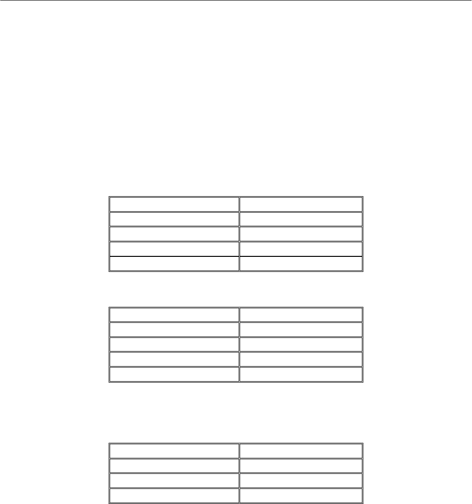
STATUS DESCRIPTION LED COLOR/ICON AUDIBLE TONE DISPLAY
Normal Power On Five Beeps All display
Version display
Correct Call Green
Transmit Red
Busy Channel Yellow
Priority Icon
Button Single Beep
Two Tone received Icon Two Beeps U/D
Warning Time out timer Two Beeps tot
Busy channel Lock Out
Two Beeps bLock out
Penalty Two Beeps Penalty
Penalty End Single Beep
Call Busy Call Busy
PTT Lock Close
Scanning In Normal Scan Mode Green Led Blinking
Icon
In Priority Scan Mode Green Led Blinking
Icon
Scan Delete Single Beep delete
Scan All Delete Single Beep All del
Transmit Inhibit In
Scanning Two Beeps Inhibit
Receive Only-No TX Two Beeps RX only
Error EEPROM Error Two Beeps Eprom Err
Out of Lock Red blinking Two beeps unLock
PLL Error
Mode Pc Program Read Red Blinking Prog- r
Pc Program Write Green Blinking Prog-w
Clone Master Red blinking Master
Clone Slave Green Blinking Slave
Clone end Turn OFF
Scan List Editing Green SCAN EDIT
PSCAN List Editing Red PSCAN EDI

Maxon SM5102Radio
3. BASIC Operation
■ Function keys
There will be six push-buttons on the face of the SM5102; Up, Down, P1, P2, P3 and Emergency. below are
the default programming settings.
■ Up button/ Down key
- This button will allow the operator to scroll up/down through the available channel. A press-and-release of
this button will increase/decrease the channel number. A press-and-hold will scroll through the succeeding
channel num.
-Push to select a transmit code channel after pushing [Two Tone code Channel select]
-Push to select a DTMF channel after pushing [DTMF Code Channel Select]
-Push to select a SMS channel after pushing [ SMS Code Channel Select]
■ Programmable function keys
- The following functions can be assigned to [P1],[P2],[P3] programmable function keys.
[Power key]
- Push to toggle the transmit Output power between High and Low
- Each channel can be programmed via the PC programmer and KEY to a high-power output, 50 Watts, and
a low-power output, 5 Watt.
[Light Key]
- Push to toggle the auto mode or Light off mode.
- AUTO Mode/OFF Mode is Selectable using Light Key. In case of Auto Mode, as pressed the key, the light
is bright during the 5 s.
[Monitor Key]
- By pressing one of the option buttons programmed to be the Monitor button, the user shall defeat the
programmed squelch operation and un-mute the speaker on the selected channel.
[Lock Key]
- This function can disable all keys except PTT, Emergency Key.
[Scan Key]
- Push to start and cancel scanning operation.
[Public address Key]
- Located under Programmable key, user selectable on or off. When selected and external speaker is
attached the radio will output voice audio over the external speaker.
[Two Tone Key]
- Push and toggle the radio enable or disable Two Tone mode
[SMS Key]
- Push to enter the SMS code channel selection mode.
- Then set the desired channel using [ UP/DOWN]
- And then Push to transmit the SMS code in the SMS code selection mode .
[1200/2400 bps Key]
- Push and toggle the SMS baud rate 1200 bps or 2400 bps.
[DTMF Key]
- Push to enter the DTMF code channel selection mode.
- Then set the desired channel using [UP/DOWN]
- And then Push to transmit the DTMF code in the DTMF code selection mode .
[GROUP Key]
- Push to enter the group selection mode.
- Then set the desired group using [UP/DOWN]
- And then Push [GROUP ] to select the group number.

MaxonSM5102Radio
■ Emergency KEY
– When emergency button is pushed, an emergency signal is automatically transmitted for the specified time
period. This is where the DTMF tone to be transmitted as the Emergency Call can be entered. After the
emergency call, the transceiver performs transmission and reception alternately with the following conditions:
- Transmits the microphone signals
- Receives the signal and emits audio
When Press the PTT, the function is cancelled.
■ Two Tone Code Channel Selection
If the transceiver has [Two Tone] assigned to it, the automatic Two Tone transmission/reception function is
available.
To enable/disable Two Tone, Push the [Two Tone] key assigned by two tone function.
This function key is toggled.
■ DTMF Code Channel Selection
If the transceiver has [DTMF] assigned to it, the automatic DTMF transmission function is available. Up to 9
DTMF channels are available:
To Select DTMF code Channel:
- Push [ DTMF ] – a DTMF Code channel appears
- Push [UP] or [DOWN] to select the desired DTMF Code channel.
- Push [ DTMF ] to transmit the DTMF Code in selected DTMF channel.
■ SMS Code Channel Selection
If the transceiver has [SMS] assigned to it, the automatic SMS transmission function is available. Up to 9
SMS channels are available:
To select SMS code Channel
- Push [ SMS ] – a SMS Code channel appears
- Push [UP] or [DOWN] to select the desired SMS Code channel.
- Push [ SMS ] to transmit the SMS Code in selected SMS channel.
To change the baud rate:
- Push [1200/2400 bps]
■ SCAN Edit Mode
- You can edit your pre-programmed Group Scan List by adding or deleting scan list from the Group Scan
List. To activate scan list editing, press and hold the P1 button on the front of the radio and turn volume on
the radio. Upon entering the scan list edit function, the LCD displays the “Scan Edit ” message. To exit the
scan list edit function, turn volume off the radio.
1. Select the Scan Group
Each Scan Group would be displayed as “xx_nnn”. xx means group, and nnn means Channel. To activate
scan list editing for selected group, press the P1 button. You can change the Scan Group Number by up or
down button.
2. Adding or Deleting to Scan List
If each channel is in the ‘Scan Editable List’, Channel Number would display Scan Icon, . To add or delete
each channel to Scan Editable List, use P2 button.
■ Priority SCAN Channel Edit
Priority Channel can be setup by PC programmer. Priority Scan List is also editable by the radio. It is called
‘Priority Channel Edit Mode’. If turn on the radio with pressing P2 Button, the radio enters Priority Channel
Edit Mode. In the Priority Edit Mode, the LCD displays the “PscanEdit” message.
1.Select the Priority Group
Each Scan Group dispalys “xx_nnn”. ‘xx’ means the current Group and ‘nnn’ means channel. To activate P
scan list editing for selected Priority group, press the P1 button. You can change the Priority Group Number
by up or down button.

Maxon SM5102Radio
2.Adding or Deleting to P Scan List
If each Channel is included in P Scan Editable List, Channel Number would display P scan Icon. To add or
delete channel from P Scan Editable List, use P2 button.
■ Programming
When the SM-2000/5000 Series is powered from the programming interface, the MCU checks PC-program
Enable port. If the PC-program enable port is active status, the MCU enters programming Mode. The LCD
display” ProGram”
1. Reading
SM-2000 / 5000 assumes PC is ready to receive data. So, If user send the serial Commands though the
interface boards, SM-2000 / 5000 will transmit the data. During this sequence, the Red LED is flashed. In PC
program Reading Mode, the LCD displays “Prog-r”.
2. Writing
SM-2000 / 5000 assumes PC is ready to transmit data. If user send the serial Commands though the
interface boards, SM-2000 / 5000 will notify this situation and then make ready to receive the data from PC.
After that, the radio informed PC of this status, then PC starts the transmission of data. During this sequence,
the Green LED is flashed. In the PC program Writing Mode, the LCD displays “Prog-w”.
■ Clone
1.Push and hold UP button when radio turn power on. In this mode, radio will display “Master”. The mode is
the master wait mode.
2. Push and hold DOWN button when radio turn power on. In this mode, radio will display “Slave” with green
led blinking.
3.Connect the cloning cable.
4.Push the master radio DOWN button.
5.After cloning, the slave radio display “ TURN OFF” message, and the master radio display ” MASTER”
message on LCD.
4. BASIC FEATURES
■ 208Channels
The SM5000 Series radio can store up to 208 channels within the same band. These channels can be
selected by turning S/W.
■ Channel Spacing
The SM-5000 Series is capable of programmable channel spacing. Each channel can be programmed via
the PC programmer, having 12.5KHz or 25KHz channel spacing.
■ Output Power
Each channel can be programmed via the PC programmer and KEY to a high-power output, 50 Watts, and a
low-power output, 5 Watt.
■ Beep On/Off Mode
All Beep tones can be globally enabled or disabled via the PC programmer. Power Up alert shall be disabled
when Power UP Alert are globally disabled.
■ Light Mode
AUTO Mode/OFF Mode is Selectable using Key. In case of Auto Mode, as pressed the key, the light is bright
during the 5 s.
■ Public Address
When selected and external speaker is attached the radio will output voice audio over the external speaker.
The radio does not TX a carrier in this mode. P/A will be shown in display when selected. When active allows
operator to enable an external speaker and transmit microphone audio only.
■ Microphone Hook
Dealer programmable function. Turned OFF user is not required to ground microphone hook. All decode and
scan functions remain the same. Turned ON user is required to ground microphone hook. When microphone
is removed from ground all tone decode functions are disabled, scan function is dealer programmable as on
or off with microphone removed from hook. Default is off with scan disabled.

MaxonSM5102Radio
■ Squelch Options
The Radio supports 3 kinds of Squelch Options. Different Squelch option can be applied to each channel.
1. CTCSS
38 kinds of TIA/EIA Standard CTCSS Tones can be set up. All tones can be set up using PC Programmer.
- TX Operation: If PTT key is pressed, the Radio occurs CTCSS tone, which is programmed to each channel
and goes TX mode. Tone would occur during TX.
- TX close: When TX mode closes, the Squelch Tail Elimination of the radio would work.
- RX Operation: If the CTCSS Tone is detected, the Radio status would be changed from Busy to Correct
Call. If the CTCSS Tone is not detected, the radio would keep Busy or be changed from Correct Call to Busy.
2. DCS
The radio supports 83 kinds of TIA/EIA Normal/Inverted DCS Data.
- TX Operation: If PTT key is pressed, the Radio occurs DCS Bit pattern of each channel and goes into TX
mode. DCS Bit pattern would occur during TX.
- TX close: When TX mode closes, Squelch Tail Elimination of the radio occurs. At this time, Turn Off Code
would be transmitted.
- RX Operation: If the DCS Data Stream is detected, the radio status would be changed from Busy to Correct
Call. If the DCS Data Stream is not detected, the Radio would keep Busy or be changed from Correct Call to
Busy.
3. Squelch Defeat (Monitor) operation
If the Monitor button is assigned by PC programmer, squelch defeat function would be run by pressing
Monitor button. If Press the Monitor button, Squelch option would be closed and you can hear the audio
sound through the speaker. If Release the Monitor button, Squelch option would work again.
■ Transmit Time-Out-Timer/TX Penalty
Time-out is a dealer programmable time from 0 – 990 seconds which is the allowed time for a sustained
transmission. TX inhibit does not allow a transmission for a dealer programmed time from 0 – 75 s after the
time –out has expired to allow a cool off period for the transmitter.
■ Busy Channel Lockout/Marked Idle
The transceiver has several inhibit function which restrict transmission under the following conditions
- Busy Channel Lockout – ON: Upon PTT being pressed, if carrier is present, the radio shall not transmit and
an audible alert tone will be given.
- Busy Channel Lockout – OFF: Upon PTT being pressed, the radio shall transmit regardless of the presence
of carrier.
- Marked Idle enabled: Can only be enabled if Busy Channel Lockout is ON. If the Busy Channel Lockout is
on and carrier is detected, the radio shall be permitted to transmit if the RX squelch option is valid.
- Marked Idle disabled: Eliminates Marked Idle and defaults back to ‘Busy Channel Lockout’.
■ PTT Lockout
The radio will allow transmission according to radio busy status.
- Off : ‘Off’ allows PTT to operate regardless of whether the radio is in an open state (monitor open) or not,
and does not change the state of the radio.
- Auto Open: ‘Auto Open’ opens the monitor of the radio after pressing PTT.
- Lock PTT : ‘Lock PTT’ prevents the keying of PTT unless the radio is open
■ Scanning
This feature will support three different scanning types. Dealer programming enables each scan type.
- Normal Scan
- Priority Scan
- Priority Look-back
Once the radio has enabled scan, it will traverse through the pre-programmed scan list. The time spent on
receiving a channel in the scan list is referred to as the scan speed. When an incoming call is detected and
decoded, scanning shall stop and the radio will un-mute. After the call has ended, the radio shall enter Scan
Delay Mode for a pre-programmed period of time. If the radio receives a call from the same caller before the
Scan Delay expires, the radio will re-enter the Scan Delay Mode and that period of time will reset. If the user
is permitted to respond to the caller, the Scan Delay will be reset. When the Scan Delay expires, the radio
shall resume scanning

Maxon SM5102Radio
■ Normal Scan
Any number of channels shall be entered into the scan list. This will be equal to or less than the number of
programmed channels. The LED shall flash green if programmed to. The flashing green LED will stop when
‘CARRIER’, or ‘CARRIER AND CORRECT TONE’. During scan delay, the LED shall remain clear. When
Scan Delay expires and Scan Speed resumes, the LED shall also resume flashing green.
■ Priority Scan
A priority channel can be programmed at the initial radio set-up stage. The priority channel will be part of the
list of channels that make up the scan list. The priority channel when used with other scanned channels will
operate as follows: P1→S1→P1→S2→P1→S3→P1→S4→P1, etc.
■ Priority Look Back Scan
One channel can be programmed by the dealer to be the Priority channel, which will enable ‘Look-back’.
This mode of operation can be used outside of the normal scanning mode. Pressing the Scan button shall
activate Priority Look-back. The Priority Look-back causes the radio to periodically ‘Look-back’ to the priority
channel for the presence of a carrier regardless of the channel that the user may be on. The frequency that
the radio will ‘Look-back’ to the priority channel can be programmed between 1 to 7 seconds in 1-second
increments. When carrier, or carrier and tone, are removed, the radio will revert back to the previously
selected channel.
■ Transmitting during Scanning
The radio shall be set to behave in a number of ways when the PTT is pressed during Scan.
- Priority Scan TX – The radio can be set to transmit on the channel on which activity has been
detected -OR- transmit on the priority channel if scanning is still active.
- Priority Only TX – If scanning, or listening to an active channel, and the PTT bar is pressed the radio
will only transmit on the priority channel. No transmissions shall be allowed to scanned calls. If
transmission is attempted a warning tone will be sounded.
- Rx only, No TX – No transmissions allowed during scanning. If transmission is attempted a warning
tone will be sounded.
- Normal Scan TX – Radio will only transmit on a stopped channel i.e. to return a call. Attempting to
transmit during scanning will cause a warning alert.
■ Scan Channel Delete
Pressing the ‘Monitor’ key, (when in scan mode and stopped on the channel) shall temporarily delete the
channel from the scan list. This shall remove that channel from the scan list until the channel is changed or
the radio’s power is reset. When power is restored or the scan list channel position is selected again, the
originally programmed scan list shall be activated.
■ DTMF
1. Receiving an DTMF
- When an DTMF is received
DTMF data is displayed
- When the received DTMF includes more than 8 characters, “►” appear.
Push any button to return to the standby condition.
2. Transmitting an DTMF
- 9 DTMF memory channels are available and the messages can be edited via PC Programming and ACC-
703.
2.1 DTMF Transmission
2.1.1 Using call memory by PC Programming
○1 Push [DTMF]to enter the DTMF code memory channel selection mode. Up to 9 DTMF channels are
available:
○2 Push [ DTMF ] – a DTMF Code channel appears
○3 Push [UP] or [DOWN] to select the desired DTMF Code channel.
○4 Push [ DTMF ] to transmit the DTMF Code in selected DTMF channel.
2.1.2 Direct code entry with ACC-703
2.1.2.1 Manual dial Operation
○1 . while in the standby condition, push [STR] 1 times, to enter the DTMF mode.
- display ”DTMF”

MaxonSM5102Radio
○2 Push the appropriate [0]-[9], A,B,C,D,*,# to enter the desired character.
○3 Push the CLR Key. Number or character will be deleted at last Number or character.
○4 Push and hold the CLR key. All messages will be deleted. the radio enter the standby mode.
○5 Push the RCL key. Press the number key. DTMF message which is stored number is displayed at LCD.
○6 Push the RCL Key. Press the #,* key to removed the displayed data from the LCD. the radio enter the
standby mode.
○7 Push and hold the RCL Key. the radio is changed with Number mode and Alphabet mode.
○8 Push and hold the STR Key to blink the cursor. Push [*] to move the cursor to left. Push[#] to move the
cursor to the right
○9 Push the STR Key in the edit mode. Press the number key. DTMF message is stored
-display[STORE Num]
○10 Push the SND key to transmitter the DTMF data.
2.1.2.2 Clearing a Dialed Number
When a number has been accidentally entered during auto dial a press and release of the CLR key will
delete an individual number. A press and hold of the CLR key will clear the entire dialed number.
2.1.2.3 To Store a Number in Memory
Dial the desired number. Entered number will show in the radio display.
Press and release the STR key.
Press and release any number 0 – 9 to store the number, * and # cannot be used for storing a number.
STORed will show in the radio display indicating the number has been stored in memory under that key.
2.1.2.4 To Recall a Stored number from Memory
Press and release the RCL key.
Press and release the number key from which a number has been stored.
Press SND to dial the recalled number.
If a number has been accidentally recalled repeat steps 1. and 2. until the proper number has been recalled.
2.1.2.5 Clearing a Stored Number
Press and release the RCL key.
Press and release the number key from which a number has been stored. The stored number will show in
the radio display.
Press and hold the CLR key to remove the stored number. A new number can now be entered and stored in
that location.
2.1.2.5 Decode action
● Stun – this shall prevent any transmission from the radio and will also mute the speaker.
● Revive – this shall re-activate the radio.
● Covert On – a valid address shall cause the radio to cycle between Tx mode and Rx mode. The time
periods spent in Tx and Rx modes shall be programmed into the addressee radio, however, it will be the
Base Station or DTMF Sender, that remotely turns this feature ON or OFF.
● Covert Off – this shall remotely turn the radios’ covert mode off, i.e. the radio will return back to passive
receive mode.
■ SMS
1. Receiving an SMS
- When an SMS is received : the SMS data is displayed
- When the received SMS includes more than 8 characters, “►” appear.
Push any button to return to the standby condition.
2. Received message selection
-The Radio memorizes the received messaged for record. UP to 9 messages for SMS, of 40 character SMS
can be memorized. The oldest message is erased when the 10th message is received. However, once the
radio is powered off, all messages are cleared.
○1 .Push [SMS] : displays “RECORD”
○2 .Push[SMS] : Displays message memory
○3 .Push [ UP] or [DOWN] to select the desired message
- When selecting the SMS that includes more than 8 characters, “►” appear.

Maxon SM5102Radio
○4 . Push and hold the ACC-703 [STR ] button to enter the message scroll mode.
○5 . Push the ACC-703 [#],[ * ] button to scroll the messages.
○6 . Push [SMS] : again to return to the standby condition
3. Transmitting an SMS
- 9 SMS memory channels are available and the messages can be edited via PC Programming and ACC-
703.
3.1 SMS Transmission
3.1.1 Using SMS memory by PC Programming
○1 Push [SMS] to enter the SMS code memory channel selection mode. Up to 9 SMS channels are
available:
○2 Push [UP] or [DOWN] to select the desired SMS Code channel.
○3 Push [ SMS ] to transmit the SMS Code in selected SMS channel.
3.1.2 Direct code entry with ACC-703
○1 During standby condition, push [STR] 3 times, to enter the SMS mode.
- Display ”SMS”
○2 Push the appropriate digit key,[0],[9], to enter the desired character.
○3 Push the CLR Key. Number or character will be deleted at cursor.
○4 Push and hold the CLR key. All messages will be deleted. the radio enter the standby mode.
○5 Push the RCL key. Press the number key. SMS message which is stored number is displayed at LCD.
○6 Push the RCL Key. Press the #,* key to removed the displayed data from the LCD. the radio enter the
standby mode.
○7 Push and hold the RCL Key. the radio is changed with Number mode and Alphabet mode.
○8 Push and hold the # key to work the space key.
○9 Push and hold the STR Key to blink the cursor. Push [*] to move the cursor to left. Push [#] to move the
cursor to the right
○10 Push the STR Key in the edit mode. Press the number key. SMS message is stored
-Display[STORE Num]
○11 Push the SND key to transmitter the SMS data.
■ TWO TONE
1. Two Tone Option
1.1 Two Tone Enable/Disable
- Enable : can receive/transmit two tone.
- Disable : cannot receive/transmit two tone
1.2 Two Tone Decoding Alert
- Enable : It rings alert sound when the radio detects two tone correctly and if no action, alert sound every
3seconds.(but first time, alert sound in 10 seconds one time)
If you do any action after detecting two tone(ex: push a key or change volume level etc…), then stop
the alert sound.
- Disable : No alert sound
1.3 Every Time Two Tone Detect
- Enable : Check the Two Tone whether correct or not whenever receive a Two Tone signal.
- Disable : Check the Two Tone one time only when receive a Two Tone signal firstly,
From Next time, don’t check the Two Tone. If you change to another channel,
Radio will repeat above.
2. Two Tone En/Decoding
You can set Individual, Group, Super Group 3 kinds of Two Tones.
2.1 Lead In Time : The time until transmit two tone after pressing PTT key.
2.2 Tone Time : The length of Tone A or Tone B
2.3 Gap Time : The length between tone A and tone B.
2.4 Two Tone Type : You can set a desire Two Tone type with PC Programmer at each channel
- Decoding : It must be correct all tone A, Gap, tone B time and frequency to open speaker.
- Encoding : Transmit Two Tone setting frequency (tone A, gap, tone B) after PTT.
MaxonSM5102Radio
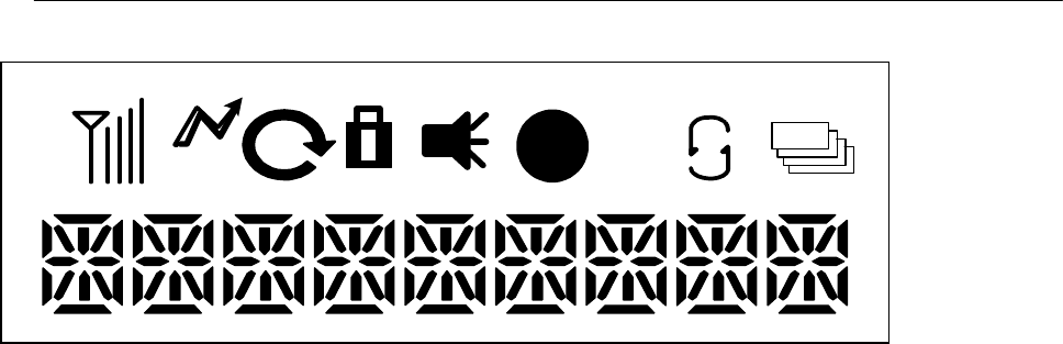
5. FUNCTION Display
֠
֠֠
֠
PL
LL
L
23
4
567890
1
1 Signal strength indicator : Indicates relative signal strength level
2 TX Indicator :Appears while transmitting
3 Scan Indicator : Appears at the scan Channel
4 P Scan Indicator : Appears at the Priority scan Channel
5 Key Lock Indicator : Appears during the key lock function is on.
6 Speaker Indicator : Appears when the monitor mode
7 Low Power Indicator : Appears when low output power is selected.
8 Two Tone Detect Indicator: Appears when the Two Tone code is received.
9 Scrambler Indicator
10 Commander Indicator
Maxon SM5102Radio
6. PC Programmer
■
Computer
Pentium II processor or faster (recommended)
■
Operating System
Microsoft Windows
®
98, 2000, NT, XP
7. Program Cable Block
■
Pc Program & Auto Test Program
15 pin Connect 9 pin Connect
4 5
5 2
6 3
7 7
■
Flash Cable
15 pin Connect 9 pin Connect
1 1,5
2 2
3 3
4 5,1,GND
■
Clone Cable
15 pin Connect 15 pin Connect
4 5
5 6
6 5

MaxonSM5102Radio
4 TROUBLE SHOOTING GUIDE
SYMPTOMS CAUSES COUNTERMEASURES
Unit does not Work
1. Complete discharge of battery
(13.8V+/-10%)
2. Regulator
3. 5v voltage source
1. Replace battery.
2. Replace regulator(U20)
3. IC1.Q20 (5v+/-0.2v)
Warning tone& No Work
1. Pll error
2. Filtering Error
3. EEPROM Fail
1. Check U1.Y2.U6
2. Check LPF
3. Re-programming
4. Replace or charge battery
Bad RX Sensitivity
(-10 to -60dB)
1. Defective ANT sw
2. Defective front-end
3. Defective DBM
4. IF IC
5. VCO level drop
6. Change of 1'st local frequency
1. Check D1.2.15
2. Check Q601
3. Check D4,T1,T2
4. Replace U2
5. RX VCO level >2dBm
6. Retune TCXO
Defective RX
1. VCO frequency change or
level drop
2. Defective voltage Source
1. Repair VCO
Defective IF IC
2. Q20
PLL Error
1. Defective 12.8 MHz TCXO
2. Voltage source for RX VCO/
TX VCO
3. Defective PLL IC
1. Replace TCXO.
2. Check RX VCO/TX VCO
3. Replace U1
NO TX Power
1. TX buffer APC
2. Power module
3. APC control
1. Check Q13.12.
2. Replace Power module Q39.28
3. Check Q14.15.16.U11
Low TX power output 1. APC 1. Re-adjust RV1
No modulation 1. SW IC & mic amp IC 1. Check U9.U13.U4
No programming 1. short protector VCC 1. Defective programming lead
NO S.A.T 1. U13 1. Check U13
Maxon SM5102Radio
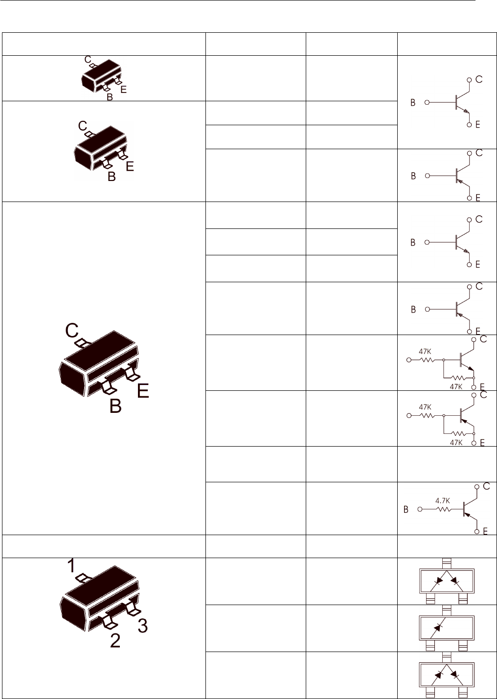
BASE DIAGRAM
BASE DIAGRAM MANUFACTURER’S
PART NUMBER REFERENCE NO.
SYMBOL
KTC5084
KTC3880 Q202.203.302.303
AT-41532 Q601
KTC4075 Q41.42.43.44.46
KTA2014 Q602.641.643
PBR951 Q12
BFR92A .Q3.2.13
KTC3875S Q901.904.7
KTA1504S Q902.903
KRC104S (ND)
KRC101SNA
KRC404V
Q5.6.8.10.16
.19.22.26.27.30.32
34.37.38.48
KRA104S (PD)
KRA304V]
KRA310V
KRA226
Q9
KRC110S (NK)
KRA110S (PK)
KRA101S
KRA104
Q1.4.11.29.31.33.
36.40.204.304
BASE DIAGRAM MANUFACTURER’S
PART NUMBER REFERENCE NO.
SYMBOL
KDS181 (A3)
KDS184 D11.12.8.11.12.
17
KDS193 (F3) D20
KDS226 (C3)
KDS122V
KDS120V
.D601
D201.202
D16.18
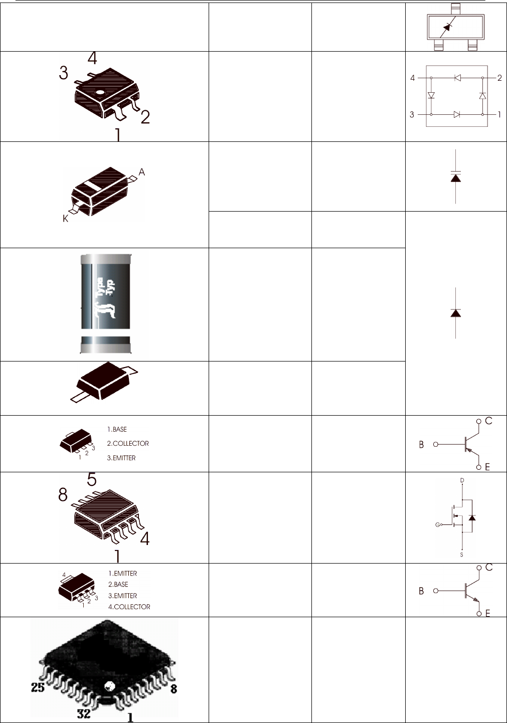
MaxonSM5102Radio
ZENER (5.6V) D23.22.5
HSMS-2817 D911
1SV229
1SV217
MMBV109
HVU300ATRU
1SS314
KDS121V
D201.202.301
D701.901.921
KDS160
KDS114 D10
SM4004
UPP9401 D.2..15
KTA1663 Q722
Q23
SI4412DY
BFG35
BLT50
XRC5640C.QFP AUDIO
(AUDIO PROCESSOR)
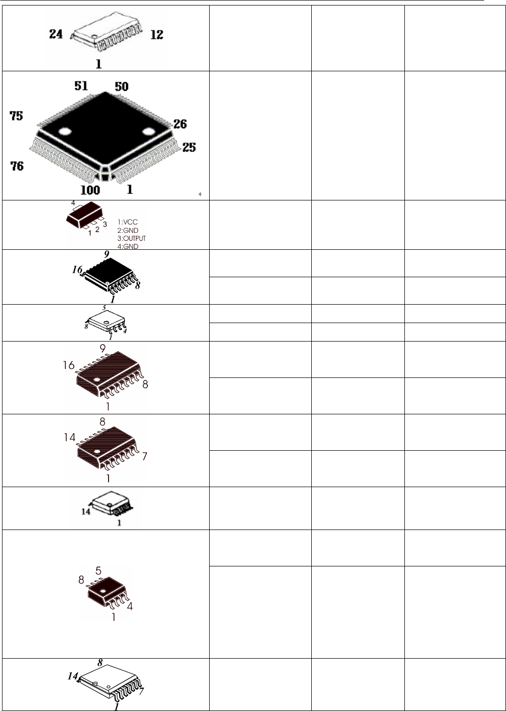
Maxon SM5102Radio
FX828D5
MT8870D
CMX881 U13.34 Codec IC
HD6473837UX
U18 MCU
KIA324F Voltage Detector IC
MB15E03SL
U1 PLL IC
TA31136FN
U2 IF IC
NJM12903V Comparator
NJM12904V OP AMP
MC14053BD IC406 MUX./DEMUX.
MC14066BD
MAX232
U3 Analog S/W IC
DBL5020V
KIA324F OP AMP
COMPANDER
NJM12904V
OP-AMP
CAT25C32/64
U6 EEPROM
LM386M
TDA7233D
KIA358
JRC2073
KIA358
LM358
AD5300
IC203
U4.5.9.11.12.
15.16.7 AUDIO AMP
MSNBLPS 6TH SWITCHED
CAPACITOR LPF
IC
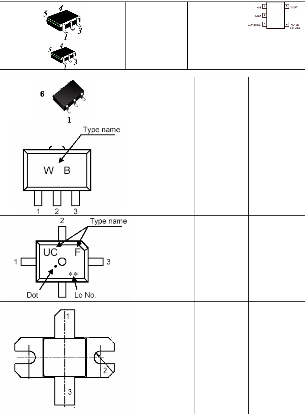
MaxonSM5102Radio
TK71750SCL
TK71733SCL
TK71730CL
IC1.U22
VOLTAGE
REGULATOR IC
TC7S66FU
KTX301E
Q101 Analog S/W IC
Dual switching TR
KRX201U
KRC824E Q103
Q107.414
Dual Switching TR
2SK3475
1(Gate)
2(Source)
3(Drain)
Q18 Silicon N-Channel
MOS TYPE
Amplifier
2SK3476
1(Gate)
2(Source)
3(Drain)
Q39 Silicon N-Channel
MOS TYPE
Amplifier
RD60HUF1
RD70HVF1
RD30HVF1
1(Drain)
2(Source)
3(Gate)
Q28 MOSFET Power
Tr
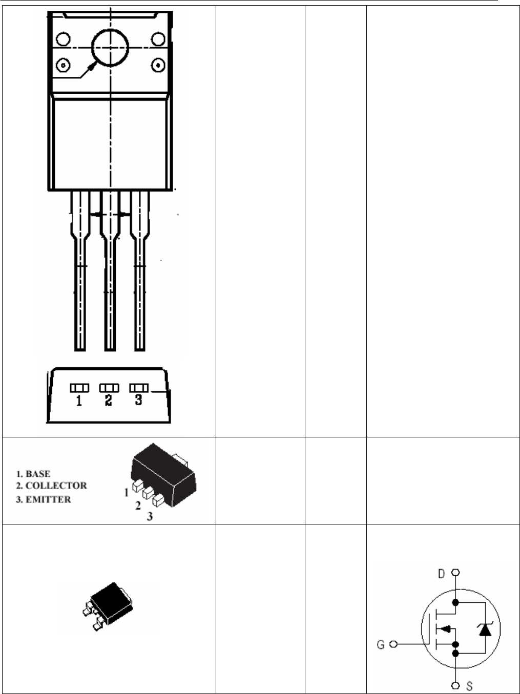
Maxon SM5102Radio
KTB1367
1(BASE)
2(COLLECTOR)
3(EMITTER)
KTA7808
1(EMITTER)
2(COLLECTOR)
3(BASE)
U20.Q14 PNP Transistor
KTA1663 Q23.47 PNP Epitaxial PlanarTransistor
MTD20N06HDL
Q25
HDTMOS E-FET TR