Maxon Electronics Australia MM-5500PRO Wireless CDMA 1XEVDO Ethernet Modem User Manual MM 5100 Control Box
Maxon Electronics Australia Pty. Ltd. Wireless CDMA 1XEVDO Ethernet Modem MM 5100 Control Box
UserManual.wiki
>
Maxon Electronics Australia
>
MM 5500PRO User Manual
Users Manual
Navigation menu
Upload a User Manual
Namespaces
Wiki Guide
HTML
PDF
Info
Views
User Manual
Discussion / Help
Navigation
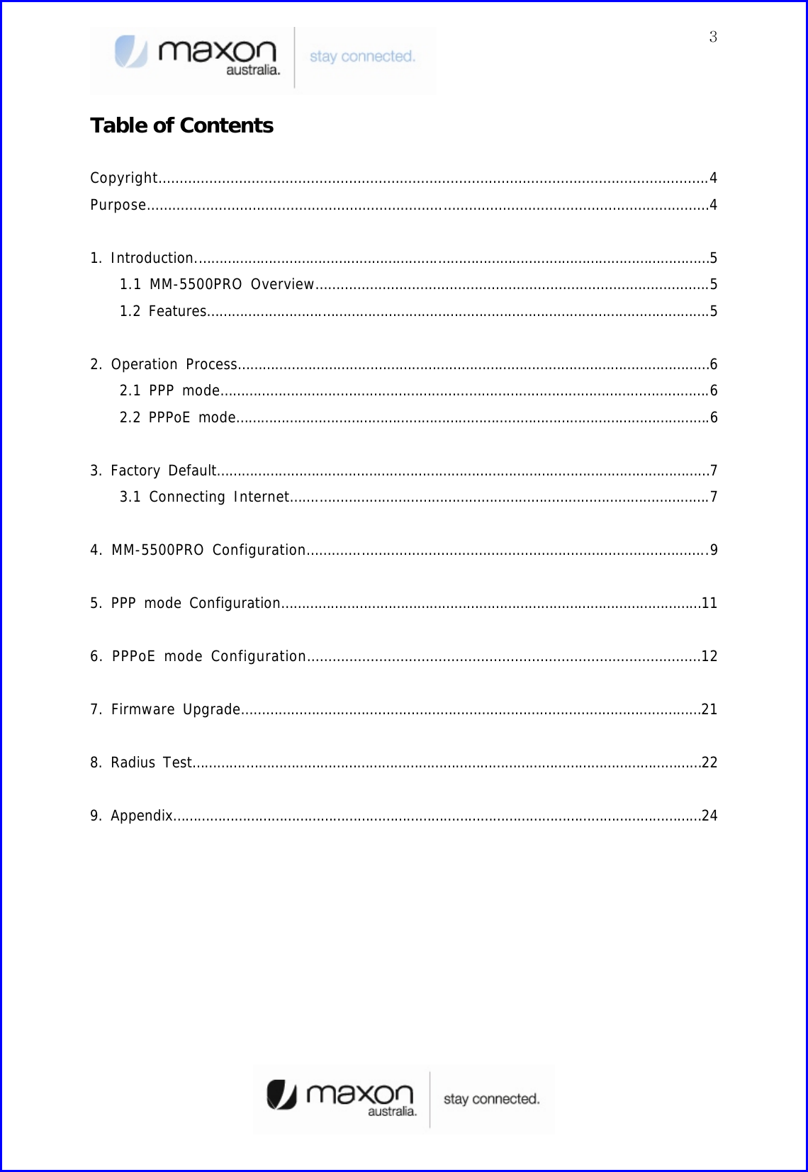
![51. Introduction 1.1 MM-5500PRO Overview There are a lot of connections for Internet. Figure 1 shows one of the connectivity on the internet using a normal ADSL modem. [Figure 1. Normal Network using an ADSL Modem] MM-5500PRO is an wireless ethernet modem that supports the connection between LAN (Local Area Network) to WAN(Wide Area Network) wirelessly in Small Office Home Office. Figure 2 shows the MM-5500PRO’s shape. [Figure 2. Each part name of MM-5500PRO] MM-5500PRO supports WAN protocol like PPP, HDLC etc. using CDMA 1x EVDO modem, routing and bridging functions internally for the high speed data transfer. 1.2 Features](https://usermanual.wiki/Maxon-Electronics-Australia/MM-5500PRO/User-Guide-577415-Page-5.png)
![62. Operation Process There are two-way of MM-5500PRO operation. One is PPP (Point to Point Protocol) mode and the other one is PPPoE(PPP over Ethernet) mode. 2.1 PPP mode On PPP mode MM-5500PRO has the IP from ISP (Internet Service Provider) itself, so MM-5500PRO can share the IP with many Host PCs. Below figure 3 shows PPP mode operation. [Figure 3. PPP mode operation] First, Host PCs get each private IP(hereby IP-1) from MM-5500PRO via DHCP server. Second MM-5500PRO gets public/Private IP(hereby IP-2) from ISP via CDMA 1x EVDO modem. Now MM-5500PRO has two kinds of IP, one is from ISP and the other ones are to Host PCs. Third, MM-5500PRO convert network data between IP-1 and IP-2 via NAT. 2.2 PPPoE mode On PPPoE mode MM-5500PRO has no IP, just the Host PC gets IP from ISP. [Figure 4. PPPoE mode operation] Different on PPP mode, the IP from ISP goes to Host PC directly. MM-5500PRO converts protocol from PPP to PPPoE or on reverse direction, the Host PC processes all network protocols.](https://usermanual.wiki/Maxon-Electronics-Australia/MM-5500PRO/User-Guide-577415-Page-6.png)
![7 3. Factory Default MM-5500PRO is already set for normal operation. So just connect between PC and MM-5500PRO. Check the network environment of Host PC. 3.1 Connecting Internet For accessing Internet, should obtain IP automatically so refer below steps. (1) Assumed the user uses the Windows XP. For connect between PC and MM-5100PRO, click “My Network Places” choose the [properties]. [Figure 5. First step of setting the Host PC] (2) Check the “Local Area Connection”, click the mouse right button then [Properties]. [Figure 6. Second step of setting the Host PC] (3) Chose “Internet Protocol [TCP/IP]” Tab and double click the item.](https://usermanual.wiki/Maxon-Electronics-Australia/MM-5500PRO/User-Guide-577415-Page-7.png)
![8 [Figure 7. Third step of setting the Host PC] (4) Check the “Obtain an IP address automatically” then click the [OK] button. [Figure 8. Forth step of setting the Host PC] (5) Host PC’s setting is finished. Connect Power and Ethernet cable on MM-5500PRO. Wait for about 10 seconds or until the LED of PKT blinks. Connect your PC on Internet.](https://usermanual.wiki/Maxon-Electronics-Australia/MM-5500PRO/User-Guide-577415-Page-8.png)
![94. MM-5500PRO Configuration User can change the function of MM-5500PRO by configuring it for user’s purpose. Supports the web based configuration pages for simplified installation and setup. Figure 9 shows connection on MM-5500PRO’s configuration. [Figure 9. Configuration of MM-5500PRO] (1) Connect Power cable on MM-5500PRO. (2) Connect LAN cable between Host PC and MM-5500PRO. (3) Set Host PC network environment below. - Host PC IP : 192.168.0.2(except 1: 1 is MM-5500PRO) - Subnet mask : 255.255.255.0 - DNS : (omit) Figure 10 shows the window of Internet Protocol(TCP/IP) Properties. (if don’t know how to find below window, go to page 5) [Figure 10. Setting Host PC] (4) Start web browser like Internet explore then write IP address, 192.168.0.1 (by default) for connecting web page of configuration in MM-5500PRO.](https://usermanual.wiki/Maxon-Electronics-Australia/MM-5500PRO/User-Guide-577415-Page-9.png)
![10(5) The pop-up window of login page appears like figure 11. - User name: admin - Password: admin (6) “Home” page shows the system information of MM-5500PRO. [Figure 11. Home Page] ITEM Description System Name Product Name Up Time Operation time from power on Interface eth0 : Status of Ethernet0 IP ppp0 : Status of CDMA0 IP (After getting IP from ISP, this IP appears) (7) We saw the connecting web page of configuration in MM-5500PRO, now try to set each configurations for each mode.](https://usermanual.wiki/Maxon-Electronics-Australia/MM-5500PRO/User-Guide-577415-Page-10.png)
![11 5. PPP mode Configuration We assume that MM-5500PRO current mode is not PPP mode in this chapter. (1) Connect Power cable on MM-5500PRO. (2) Follow the chapter 4, connect MM-5500PRO’s configuration web page. (3) Click “PPP/PPPOE” menu then PPP/PPPOE page appears like figure 12. [Figure 12. PPP/PPPOE Page] ITEM Description Select Mode PPP User ID user@telstra.internet (or others) User Password Password Tel Number #777 CRM 1 : 1x, EVDO (By default) 150 : 1x only 160 : EVDO only (4) All setting finished then Click the button. (5) Disconnect power cable then reconnect it. (6) Follow the chapter 3, change the Host PC’s network environment. (7) Execute web browser and explore internet.](https://usermanual.wiki/Maxon-Electronics-Australia/MM-5500PRO/User-Guide-577415-Page-11.png)
![12 6. PPPoE mode Configuration We assume that MM-5500PRO current mode is not PPPoE mode in this chapter. (1) Connect Power cable on MM-5500PRO. (2) Follow the chapter 4, connect MM-5500PRO’s configuration web page. (3) Click “PPP/PPPOE” menu then PPP/PPPOE page appears like figure 13. [Figure 13. PPP/PPPOE Page] ITEM Description Select Mode PPPoE User ID Not effect User Password Not effect Tel Number Not effect CRM 1 : 1x, EVDO (By default) 150 : 1x only 160 : EVDO only (4) All setting finished then Click the button. (5) Disconnect power cable then reconnect it. (6) Follow the chapter 3, change the Host PC’s network environment.](https://usermanual.wiki/Maxon-Electronics-Australia/MM-5500PRO/User-Guide-577415-Page-12.png)
![13 (7) In this example we assumed the user uses the Windows XP. If it is not Windows XP, the user should install PPPoE connection application program. For connect between PC and MM-5500PRO click the “My Network Places” choose the [properties]. [Figure 14. First step of setting the Host PC] (8) Check the “Local Area Connection”, click the mouse right button then [Properties].](https://usermanual.wiki/Maxon-Electronics-Australia/MM-5500PRO/User-Guide-577415-Page-13.png)
![14 [Figure 15. Second step of setting the Host PC] (9) Chose Internet Protocol[TCP/IP] Tab and double click the item. [Figure 16. Third step of setting the Host PC] (10) Check the “Obtain an IP address automatically” then click the [OK] button.](https://usermanual.wiki/Maxon-Electronics-Australia/MM-5500PRO/User-Guide-577415-Page-14.png)
![15 [Figure 17. Forth step of setting the Host PC] (11) You should make PPPoE connection so click the “Create a nee connection” [Figure 18. First step of creating a PPPoE connection] (12) New Connection Wizard appears, click [Next] button.](https://usermanual.wiki/Maxon-Electronics-Australia/MM-5500PRO/User-Guide-577415-Page-15.png)
![16 [Figure 19. Second step of creating a PPPoE connection] (13) Check “Connect to the Internet” then click [Next] button. [Figure 20. Third step of creating a PPPoE connection] (14) Check “Set up my connection manually” then click [Next] button.](https://usermanual.wiki/Maxon-Electronics-Australia/MM-5500PRO/User-Guide-577415-Page-16.png)
![17 [Figure 21. Forth step of creating a PPPoE connection] (15) Check “Connect using a broadband connection that requires a user name and password” then click [Next] button. [Figure 22. Fifth step of creating a PPPoE connection]](https://usermanual.wiki/Maxon-Electronics-Australia/MM-5500PRO/User-Guide-577415-Page-17.png)
![18(16) Write the ISP Name what you want. In this example write ISP name then click [Next] button. [Figure 23. Sixth step of creating a PPPoE connection] (17) Write User name/Password/Confirm password what you use. Then click [Next] button. [Figure 24. Sixth step of creating a PPPoE connection]](https://usermanual.wiki/Maxon-Electronics-Australia/MM-5500PRO/User-Guide-577415-Page-18.png)
![19(18) All setting is finished, check “Add a shortcut to connection and close this wizard, click Finish” then click [Finish] button. [Figure 25. Seventh step of creating a PPPoE connection] (19) PPPoE connection program appears then click [Connect] button. [Figure 26. PPPoE connection application program]](https://usermanual.wiki/Maxon-Electronics-Australia/MM-5500PRO/User-Guide-577415-Page-19.png)
![20(20) Connecting window appears, trying to connect MM-5500PRO. [Figure 27. Connecting between PC and MM-5500PRO] (21) After connection between PC and MM-5500PRO, then go to the verifying stage. [Figure 28. Verifying username and password] (22) Changing Registering stage, the Host PC connecting on the network. [Figure 29. Registering PC on the network] (23) Click the [Start] button then choose Internet Explorer.](https://usermanual.wiki/Maxon-Electronics-Australia/MM-5500PRO/User-Guide-577415-Page-20.png)
![21 [Figure 30. Starting Internet Explorer] 7. Firmware Upgrade Firmware is for MM-5500PRO. When the firmware is to be upgrade or to be download, use like this. (1) Connect Power cable on MM-5500PRO. (2) Follow the chapter 4, connect MM-5500PRO’s configuration web page. (3) Click “Upgrade” menu then PPP/PPPOE page appears. (4) Click the button and search the firmware file. (5) Select the firmware file then “OK”.](https://usermanual.wiki/Maxon-Electronics-Australia/MM-5500PRO/User-Guide-577415-Page-21.png)
![22 [Figure 31. Firmware Upgrade] (6) Click the button then below Figure 31 appears. [Figure 32. Firmware Upgrade finished] (7) Execute web browser and explore internet. 8. Radius Test There is no needed RADIUS on normal using wireless AP but if connect user PC using RADIUS protocol, there are some needed to define below. (1) Wireless AP supports RADIUS protocol to communicate with MM-5500PRO. (2) ISP(Internet Service Provider) supports subnet mask 255.255.255.xxx (because Client PCs should get their IP from RADIUS Server). (3) RADIUS Client Software is installed on Client PC.](https://usermanual.wiki/Maxon-Electronics-Australia/MM-5500PRO/User-Guide-577415-Page-22.png)
![23(4) Get the RADIUS Server information including Authentication Server IP/Port and Accounting Server IP/Port. (5) IP of MM-5500PRO should be registered in advance.(But now MM-5500PRO gets Dynamic IP from ISP so after get the IP from MM-5500PRO then let the RADIUS server know the MM-5500PRO’s IP. In the future if MM-5500PRO using RADIUS protocol, MM-5500PRO needed Static IP from ISP). [Figure 33. RADIUS Authentication and Accounting Network] (6) Connect Power cable on MM-5500PRO. (7) Follow the chapter 4, connect MM-5500PRO’s configuration web page. (8) Click “RADIUS” menu then RADIUS page appears.](https://usermanual.wiki/Maxon-Electronics-Australia/MM-5500PRO/User-Guide-577415-Page-23.png)
![24 [Figure 34. RADIUS Setting Page] ITEM Description Authentication Server Server IP : xxx.xxx.x.x Server Port : xxxx Shared Secret : depend on Authentication Server Accounting Server Server IP : xxx.xxx.x.x Server Port : xxxx Shared Secret : depend on Authentication Server Server Timeout Second of time out (depend on network speed) Max.Request Time of Request (normal 2~3 times) Session Timeout Default by server Idle Timeout Default by server Interim Interval Default by server (9) All setting finished, execute the RADIUS Client Software that is installed on Client PC then connect on Internet.](https://usermanual.wiki/Maxon-Electronics-Australia/MM-5500PRO/User-Guide-577415-Page-24.png)
![25 9. Appendix Below pages are descriptions of other configuration pages. (1) “Status” page shows current protocol status. [Figure 35. Status Page] ITEM Description Select Statistics Information of Target - Device - ARP - IP - ICMP - TCP - UDP - ROUTE](https://usermanual.wiki/Maxon-Electronics-Australia/MM-5500PRO/User-Guide-577415-Page-25.png)
![26Device Statistics Each status & Information (2) “Ethernet” page shows the information of Ethernet interface. [Figure 36. Ethernet Page] ITEM Description Connect Type Static: Should be Always (Dynamic: Will be omit) IP Address eth0 IP Subnet Mask Subnet mask IP Address Gateway Gateway Address DHCP Hostname (Will be omit)](https://usermanual.wiki/Maxon-Electronics-Australia/MM-5500PRO/User-Guide-577415-Page-26.png)
![27 (3) “PPP” page shows the information of PPP authentication. [Figure 37. PPP Page] ITEM Description User ID Received ID from ISP User Password Password Tel Number Calling number (4) “DNS” page shows the information of setting DNS IP Address. [Figure 38. DNS Page]](https://usermanual.wiki/Maxon-Electronics-Australia/MM-5500PRO/User-Guide-577415-Page-27.png)
![28ITEM Description 1st DNS IP Address First DSN IP (Optional) 2nd DNS IP Address Second DSN IP (Optional) (5) “DHCP” page shows the information of setting DHCP. [Figure 39. DHCP Page] ITEM Description Activate Enable/Disable: DHCP server on-off Start IP Address Start address local IP(start range) End IP Address End address local IP(End range) Subnet Mask Subnet mask IP Address Default Lease Time Default Time of assigning IP Max Lease Time Maximum Time of assigning IP Default Gateway Gateway IP Address](https://usermanual.wiki/Maxon-Electronics-Australia/MM-5500PRO/User-Guide-577415-Page-28.png)
![29 (6) “NAT” page shows the information of setting NAT. [Figure 40. NAT Page] ITEM Description Operation Enable/Disable: NAT on-off Virtual Sever User can select/configure NAT option Access Control End address local IP(End range) DMZ Host IP Setting DMZ Host IP Address VPN Pass-Through IP VPN IP Address](https://usermanual.wiki/Maxon-Electronics-Australia/MM-5500PRO/User-Guide-577415-Page-29.png)
![30 (7) “RADIUS” page shows the information of setting RADIUS. [Figure 41. RADIUS Page] ITEM Description Server IP Authentication Server IP & Port Shared Secret RADIUS Secret Key Server IP Accounting Server IP & Port Shared Secret Accounting Secret Key Server TimeOut Waiting Time of Accounting Server Max Request Repeat time of accounting request Session Timeout Available time of session status Idle Timeout Available time of Idle status](https://usermanual.wiki/Maxon-Electronics-Australia/MM-5500PRO/User-Guide-577415-Page-30.png)
![31Interim Interval Frequent time of accounting packet (8) “SNMP” page shows the information of setting SNMP. [Figure 42. SNMP Page] ITEM Description Activate Enable/Disable Read Community Name Setting Reading authority Write Community Name Setting Writing authority System Name Setting system name System Contact Setting system contact System Location Setting system location Trap Community Name Setting Trap community](https://usermanual.wiki/Maxon-Electronics-Australia/MM-5500PRO/User-Guide-577415-Page-31.png)
![321st Trap Server IP Setting 1st Trap Server IP 2nd Trap Server IP Setting 2nd Trap Server IP Auth. Fall Trap Warning message to Trap server Cold Start Trap First booting message to Trap server Link UP Trap Normal status message to Trap server Link Down Trap Abnormal status message to Trap server (9) “SNTP” page shows the information of setting SNTP. [Figure 43. SNTP Page] ITEM Description Operation Enable/Disable: SNTP on-off SNTP Sever Address Setting SNTP server Time Zone Setting SNTP time zone](https://usermanual.wiki/Maxon-Electronics-Australia/MM-5500PRO/User-Guide-577415-Page-32.png)
![33 (10) “System” page shows the information of System. [Figure 44. System Page] ITEM Description Admin Name Name of Administrator Admin Password Setting Admin password HTTP Port HTTP Port number Telnet Daemon Enable/Disable Telnet (11) “Reboot” page makes MM-5500PRO reboot.](https://usermanual.wiki/Maxon-Electronics-Australia/MM-5500PRO/User-Guide-577415-Page-33.png)
![34 [Figure 45. Reboot Page] ITEM Description Reboot System Reboot MM-5500PRO (All document finished)](https://usermanual.wiki/Maxon-Electronics-Australia/MM-5500PRO/User-Guide-577415-Page-34.png)