Mcclane 20 3.5RP 10 User Manual FRONT THROW REEL MOWER Manuals And Guides 1006889L
User Manual: Mcclane 20-3.5RP-10 20-3.5RP-10 MCCLANE FRONT THROW REEL MOWER - Manuals and Guides View the owners manual for your MCCLANE FRONT THROW REEL MOWER #2035RP10. Home:Lawn & Garden Parts:Mclane Parts:Mclane FRONT THROW REEL MOWER Manual
Open the PDF directly: View PDF ![]() .
.
Page Count: 16
2
3
4-6
7-10
12-14
13-14
11
r
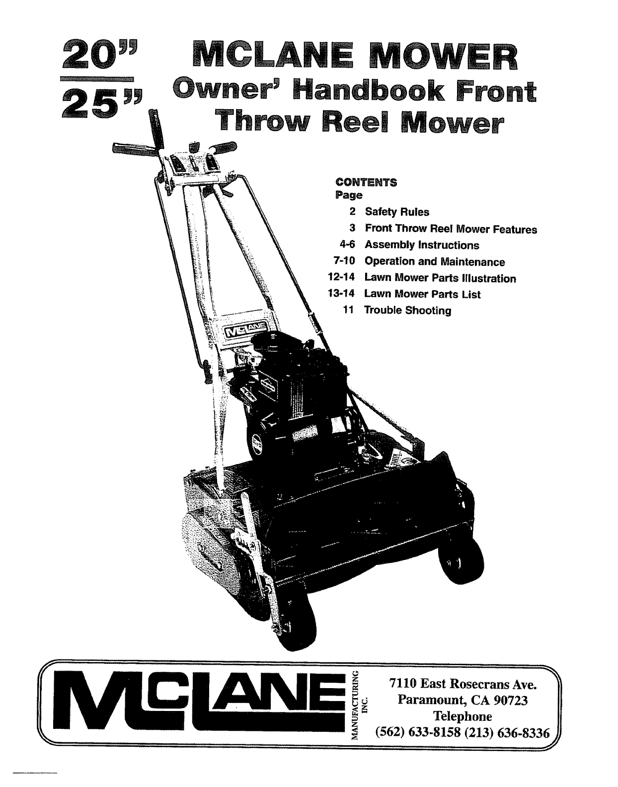
Safety Rules
Front Throw Reel Mower Features
Assembly Instructions
Operation and Maintenance
Lawn Mower Parts Illustration
Lawn Mower Parts List
Trouble Shooting
I!
z 7110 East Rosecrans Ave.
_Paramount, CA 90723
_Telephone
(562) 633:815,8 (213),636-833._ j
SAFETY RULES
Training 1. Read the Operating and ServiceInstruction Manualcarefully.Bethoroughly familiar with the controls and
proper use of the equipment.,
2.. Neverallow childrento operateapower mower.
3. Keepthe area of operationclear of all persons,particularlysmallchildren and pets_
Preparation
1. Thoroughly inspect the area wherethe equipmentis to be used and removeall stones,sticks, wire, bones
and other foreign objects+.
2. Do not operateequipmentwhen barefootor wearing opensandals.Alwayswear substantialtootwear+
3, Checkfuel before starting engine.Do not fill gasolinetank indoors,when engineis running, or while engine
is still hal Wipe off any spilled gasolinebeforestarting engine
4_ Disengageself-propelledmechanismor drive clutch on units so equippedbefore starting engine (motor)+
5o Neverattempt to makea wheel height adjustmentwhile engine(motor)is running.
6+ Mow only in day light or in goodartificial light..
7+ Never operateequipment inwet grass.Always besure of yourfooting; keep a firm hoid onthe
handleand walk, never run..
Operation 1. Do not change enginegovernorsettings oroverspeedengine.
2. Do not puts handsor feet nearor underrotating parts. Keepclear of dischargeopeningat all times.
3. Stop blade(s)when crossinggraveldrive,walks or roads..
4. After strlking a foreign object, stop the engine (motor),removewire from spark plug, thoroughly inspectthe
mower for any damage,and repairthe damage before restating and operatingthe mowe[
5+ If the equipment should start to vibrate abnormally,stop the engine (motor)and check immediatelyfor the
cause,Vibration is generallya warning of troubler
6 Stop engine (motor)wheneveryou leavethe equipment, beforecleaning mower housing,and when making
any repairs or inspections.
7. When cleaning,repairing or inspecting,make certain blade and all moving parts havestopped. Disconnect
spark plug wire and keep wire awayfrom plugto preventaccidental starting°
8. Do not run engine (motor)indoors..
9. Shut engine(motor) off and wait until bladecomes to a completestop before removinggrasscatcher and/or
uncloggingchute,
10.. Mow across the face of slopes,never up-and-down.Exerciseextreme cautionwhen changingdirection on
slopes+Donot mow excessivelysteepslopes+
1t_ Neveroperate mowerwithout properguards,platesor other safety protectivedevices inplace..
12. Keepwashout ports andother mowerhousingservice openingsclosedwhen mowing.
Maintenance
and Storage
1+ Checkblade and enginemountingbolts at frequent intervalsfor propertightness,.
2 Keepall m,_, bolts, and screws tight to be sure equipmentis in safe working condition°
3Neverstore equipmentwith gasoline in the tank inside of a buildingwhere fumes mayreach an adenflame
or spark.Allow engineto cool before storing in any enclosure.
4. To reducefire hazardkeep enginefree of grass,leavesor excessivegrease°
5 Checkgrass catcherfrequently for wear or deterioration.
TWO YEAR LIMITED WARRANTY
For two years from purchase (80 days for commemlal use) McLane Manufacturing tno, will replace for the original purchaser, free of charge, any part or parts, found upon
examiner+onby any factory authorize service center, or by the factory in Paramount, California+to be defective in material or workmanship or bo|h All transportation charges
on parts submitted for rep+acement under th_s warranty must be borne by purchaser There are no other expressed warranties, implied warranties, including those o!
memhantability and fitness for a particular purpose, are limited to two years from pumhase and to the extant permitted by law Any and air Implied warranties are excluded This
Is the exclusive remedy and liability for consequentia! damages Any and all warranties are excluded to the extent exclusion is permitted by law Some states do not allow
limitations on how long an Implied warranty lasts, and some states do not aiIow the exclusion limit.at/on of consequential damages, so the above limitatfon and exclusion may
not apply to you Th_swarranty gives yau specific tagat rights and you may also have other rights which very _lrom stats to state It is your responsibility to foIlmv the maintenance
instructions described in the owner's manual Routine service (cleanIng, blade sharpening) is your responsibility Defect of engine is covered by manufacturer of engine
McLane Manufacturing, _nc.
Note: Operator abuse and improper assembly of product is not covered tJyany written or _mpliod warranty, Read your owner's manual carefully
2
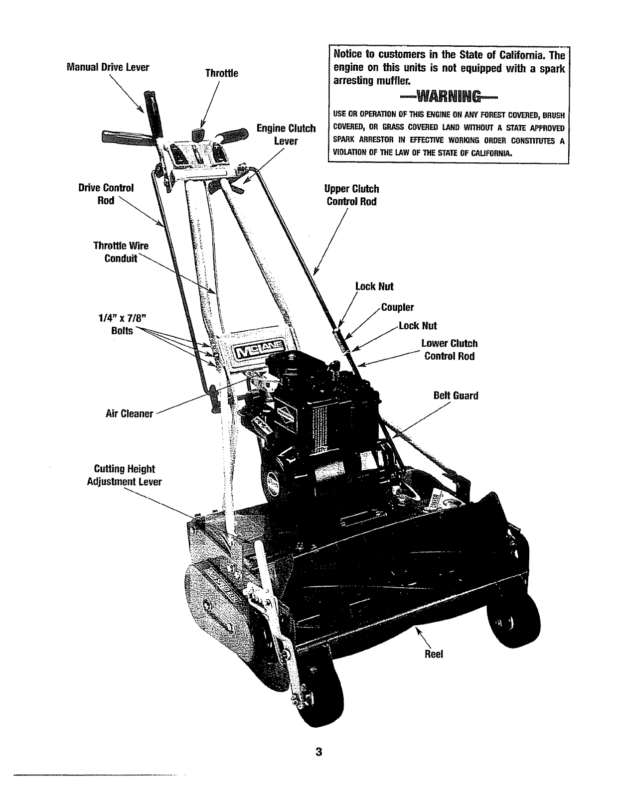
Manual Drive Lever Throttle
/Engine Clutch
Lever
Hotice to customers in the State of California. The
engine on this units is not equipped with a spark
arresting muffler.
USEOROPERATIONOFTHIS ENGINEON AW_'FORESTCOVERED,BRUSH
COVERED_OR GRASSCOVEREDLAND WITHOUTA STATE APPROVED
SPARK ARRESTORIN EFFECTIVEWORKING ORDER CONSTITUTESA
VIOLATIONOFTHE LAWOFTHE STATEOF CAUFORNIA,
Drive Conbol
Rod Upper Clutch
Cordrol Rod
Throttle Wire
Conduit_,_
1/4" X 7/8"
Air Cleaner
Cuffing Height
Adjustment Lever
_f
Lock Hut
der
Nut
Lower Clutch
._._._I Control Rod
Belt Guard
Reel
3

ASSEMBLY
TOOLS REQUIRED: 7/'16"Wrench, Pliers, Screwdriver (11/16" Wrench needed to adjust Clutch Tension)
NOTE; Reference to left or right side 2.
of the mower is from operator's
position at the handle, facing forward.
The lawn mower is fully assembled
except for the handle throttle control,
drive control rod and clutch control 3.
rod. Everything is packed and shipped
in one container.
ASSEMBLY:
1. CARTON REMOVAL
Cut the back panel, tay down pull
mower backwards,
2. PARTS ID
3. TOOLS REQUIRED
7/16" Wrench, Pliers, Screwdriver
(11/16" Wrench needed to adjust
Clutch Tension)
STEP 1: Remove the grass catcher,
handle assembly, and rods from the box
(see Fig 1, grass catcher not shown).
STEP 2: Attaching the handle: remove
the bolts retaining the panel to the lower
handle°You need six bolts to mount the
handle°Two of the six bolts were those
you just removed. The other four are
supplied with loose hardware in the
plastic bag. (see Fig 2) Take the bottom
section of the handle (Fig. 3) and install
a bolt through the brace, the upper
handle section, and the panel or
bracket° Put a nut on each bolt and
secure the panel or bracket on both
sides of the handle.
NOTE: The three holes in the upper
handle must be aligned with the three
holes in the lower handle, The handle
brace is put on the outside of the
upper handle_ Slip on the handle
grip& Soaking in hot water may ease
assembly.
DRIVE CONTROL ROD ASSEMBLY:
(see Fig. 4 &5)
1oAssemble drive control rod (one
piece rod with both ends bent), by
inserting one bent end in the drive
control lever bearing and inserting
the other end in the drive pivot rod,.
2. Secure the control rod withcotter pin&
ENGINE CLUTCH CONTROL ROD
ASSEMBLY: (see Fig.6)
1oThe clutchcontrolrodconsistsof one
long rod with one bent end, one
coupler, two lock nutsand one short
rod with one bent end,,
,,
Assemble the clutch control rod by
inserting the short rod bent end inthe
clutch bearing. The end of the rod
must be outside the belt (Fig 6)..
Insert the bent end of the long rod
in the clutch lever bearing.
Insert a cotter pin in each bent end,
but do not secure until final
adjustment is made_
IMPORTANT! ENGINE CLUTCH ROD
TENSION ADJUSTMENT: (Fig. 7)
1.,Lift the engine clutch lever to the
handle, If there is a slight tensionon
the belt, the adjustment should be
correct,. The tension should be just
enough to propel the mower and reel
without the belt slipping on the pulley.
EXCESSIVETENSIONWILL REDUCE
BELT LIFE AND PERFORMANCEOF
THE MOWER.
2 Check for correct belt tension"
! CAUTION !
A. Remove spark plug wire, engage
the clutch by lifting the clutch
lever to the handle and pull on
the rope starter..
BIf the reel turns, the tension should
be correct, however, be sure to
check if the idlerbearing is putting
excessive tension on the belt
C. If reel does not turn, more tension
is needed. Final adjustment can be
made after reel is operating.
3. ADJUSTMENT PROCEDURES:
A, Excessive Belt Tension: Remove
the upper rodfrom the clutch lever
handle and turn right (into the
coupler)one turnat atime until the
tensionis correct°
B. Increased Belt Tension Needed:
Remove the upper rod from the
clutch lever handle and turn left
(out of the coupler) one turn at a
time until the tensionis correct.
C. When the tensionis correct, insert
the upper rod into the clutch lever
handle, secure the cotter pins at
both ends of the control rod and
tighten the lock nuts to the coupler°
At this time, replace the spark plug
wirer
D Refer to the operation instruc-
tions before using mower..
_IMPORTANT !J
Without trapping bait, be sum
rod is on the outside of belt
FIGURE 1: These parts, and the
grass catcher, should have been
removed from the shipping carton_
Bra_
/// 7/-- Lower Handle J
FIGURE 2
FIGURE 3: Reuse the two bolts on the
panel, plus the other four bolts your
received, to mount the handle,

ASSEMBLY
RGURE 4: Installthe Wheel Drive Controlrod on top and insert
cotter pin.Then, open itsbottom to secureiyfastenit,
RGURE 5: Insert the rodat the bottomoftheWheel Drive Lever
andsecure withacotterpin,
FIGURE6: Put the bend end of the rodthrough the hole of the
idler brade'L Secure laterwith a cotter pin_
RGURE 7:Put the bentend ofthe rodthroughthe holeof the dr_¢e
dt_ch lever.
INSTALUNGTHROTTLE CONTROL:
1. One end of the throt_econtrolis factory installedto the
carburetor,,The other end needs to be installedin the t_3per
handle_
2_Takeholdof the controlfeverat the other end of the cableand
routethe throttle cable under and behind the panel located
where the upper handleis boltedto the lower handle°
3,.See Flgo8:Hold thecontrol leverat the end of the throttlecable
and twistitslightly so the knob will pass through the slot inthe
upper handle,,
5
RGURE 8:Tw_"tlever so knob willpass throughslot in panel,,
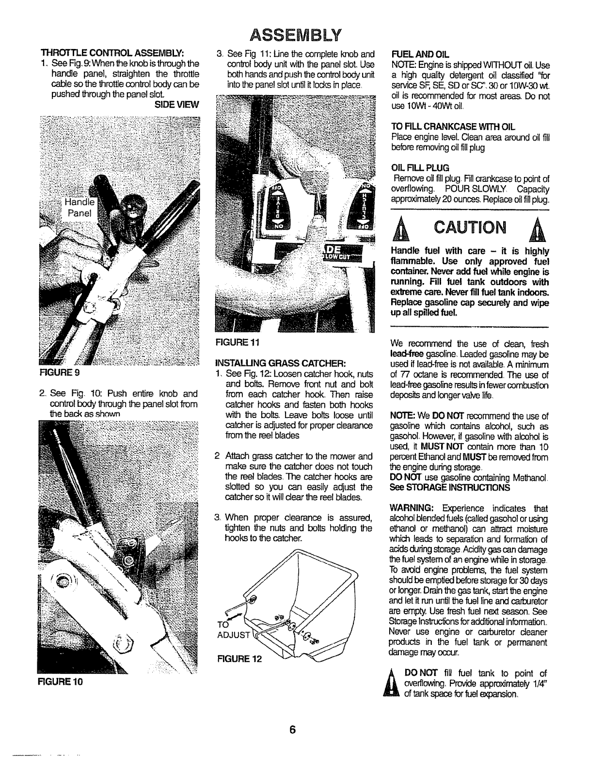
THROTTLECONTROLASSEMBLY:
1oSee Fig,9:When theknob is throughthe
handle panel, straighten the throttle
cable so the throttlecontrolbody can be
pushed throughthe panel slot.
SIDE VIEW
FIGURE 9
2, See Fig, 10: Push en_Jreknob and
controlbody throughthe panelslotfrom
the back as ,_own
RGURE 10
ASSEMBLY
3, See Fig 11: Une the completeknob and
controlbody unitwith the panelslot.Use
bothhandsandpushthecontrolbodyunit
intothe panelslo!unfititlocksin place,
FIGURE 11
INSTALUNG GRASS CATCHER:
!, See Fig.12: Loosen catcher hook, nuts
and bolts. Remove front nut and bolt
from each catcher hook, Then raise
catcher hooks and fasten beth hooks
with the bolls. Leave bolts loose until
catcher is adjustedfor proper clearance
from the reelblades
Attach grass catcher to the mower and
make sure the catcher does not touch
the reel blades The catcher hooks are
slotted so you can easily adjust the
catcherso it will clearthe reelblades.
& When proper clearance is assured,
tighten the nuts and bolts holding the
hookstothe catcher.
TO
ADJU;
FIGURE 12
FUELAND OIL
NOTE:Engineis shippedWITHOUToil.Use
a high quality detergent oil dashed 'for
serviceSF,SE,SD orSC".30or t0W-30 wt
oil is recommendedfor most area& Do not
use 1OWl-40Wt oil,
TO RLL CRANKCASEWITHOIL
Place enginelevel.,Clean area aroundoil flU
beforeremovingoilfill plug
OIL R_ PLUG
Removeoilfillplug.Fillcrarakcasetopointof
overflowing POURSLOWLY, Capacity
approximately20ounces.Replaceoilfillplug
CAUTION
Handle fuel with rare - it is highly
flammable. Use only approved fuel
container.Neveraddfuel while engineis
running. Fill fuel tank outdoors with
extremecare,Neverfill fuel tank indoors.
Replacegasolinecap securelyandwipe
upall spilledfuel.
We recommend the use of dean, fresh
lead4me gasoline Leadedgasolinemay be
used if lead-freeis notavailableA minimum
of 77 octane is recommendedThe use of
lead4reegasolineresultsinfewercombustion
depositsandlongervak,e life,
NOTE:We DO NOT recommendthe use of
gasoline which contains alcohol, such as
gasohoLHowever,if gasolinewith alcoholis
used, it MUST NOT contain more than 10
percentEthanolandMUSTberemovedfrom
1heengineduringstorage
IX) NOT use gasolinecontainingMethanol
SeeSTORAGEINSTRUCTIONS
WARNING: Experience indicates that
alcoholblendedfuels(calledgasoho]or using
ethanol or methanol)can attract moisture
which leads to separationand forma_onof
adds duringstorageAciditygas candamage
thefuelsystemof aqenginewhileinstorage
To avoid engineproblems,the fuel system
shouldbeemptiedbeforestoragefor30days
orlonger°Drainthe gas tank.,startthe engine
andlet it run u_l thefuel lineand cad3uretor
areempty.Use fresh fuel next season,,See
Storagel_ns foradcrr_bnalinformalbn.
Never use engine or carburetor cleaner
products in the fuel tank or permanent
damagemayoccur,,
_DONOT rift fuel tank to point of
overflowing,Provideapproximat_y1/4"
of tankspaceforfuelexpansion_
6
OPERATION
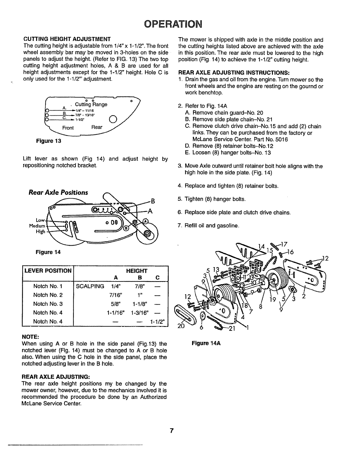
CUTTING HEIGHT ADJUSTMENT
The cutting height is adjustable from 1/4" x 1-1/2"oThe front
wheel assembly bar may be moved in 3-hofes on the side.
panels to adjust the height,, (Refer to FtGo13) The two top
cutting height adjustment holes, A&Bare used for all
height adjustments except for the 1-1/2" height. Hole Cis
only used for the 1-1/2"' adjustment..
The mower is shipped with axle in the middle position and
the cutting heights listed above are achieved with the axle
in this position_ The rear axle must be lowered to the high
position (Fig,, 14) to achieve the 1-1/2" cutting heighL
REAR AXLE ADJUSTING INSTRUCTIONS:
1,_Drain the gas and oil from the engine_'n_rn mower so the
front wheels and the engine are resting on the gournd or
work benchtop.
Figure 13
Lift lever as shown (Fig 14) and adjust height by
repositioning notched bracket.
2_
,
Refer to Fig, 14A
A,, Remove chain guard-Noo 20
B, Remove side plate chain-Nor 21
C. Remove clutch drive chain-No/15 and add (2) chain
links° They can be purchased from the factory or
McLane Service Center,, Part Noo5016
D. Remove (8) retainer bolts-No_12
E,_Loosen (8) hanger bolts-No,, 13
Move Axle outward until retainer bolt hole alignswith the
high hole in the side plate. (Fig. '14)
4. Replace and tighten (8) retainer bolts.
5., Tighten (8) hanger bolts,
6o Replace side plate and clutch drive chains_
7, Ref!ll oil and gasoline,
Figure 14
LEVER POSITRON
SCALPINGNotch No_1
Notch No,,2
Notch No. 3
Notch No. 4
Notch No. 4
HEIGHT
AS_ C
1/4" 7/8" \
7/16" '1" | 2
5/8" 1_1!8" (_-_'1_
1-1/16" 1-3/16" _k._t,,%'_._"_
1-1/2"
NOTE:
When using A or B hole in the side panel (Fig.13) the
notched lever (Fig. 14) must be changed to A or B hole
also. When using the C hole in the side panel, place the
notched adjusting lever in the B hole,,
REAR AXLE ADJUSTING:
The rear axle height positions my be changed by the
mower owner, however,due to the mechanics involved it is
recommended the procedure be done by an Authorized
McLane Service Center..
3 '11
9. 2
4 7 9
Figure 14A
7
OPERATION
CAUllON; To avoid possible damage to front wheels do not start
mowerbefore setting height adjustment Notchedheight bracketat
right front of mower (Fig, 14) must be placed at desired cutting
heightposition.
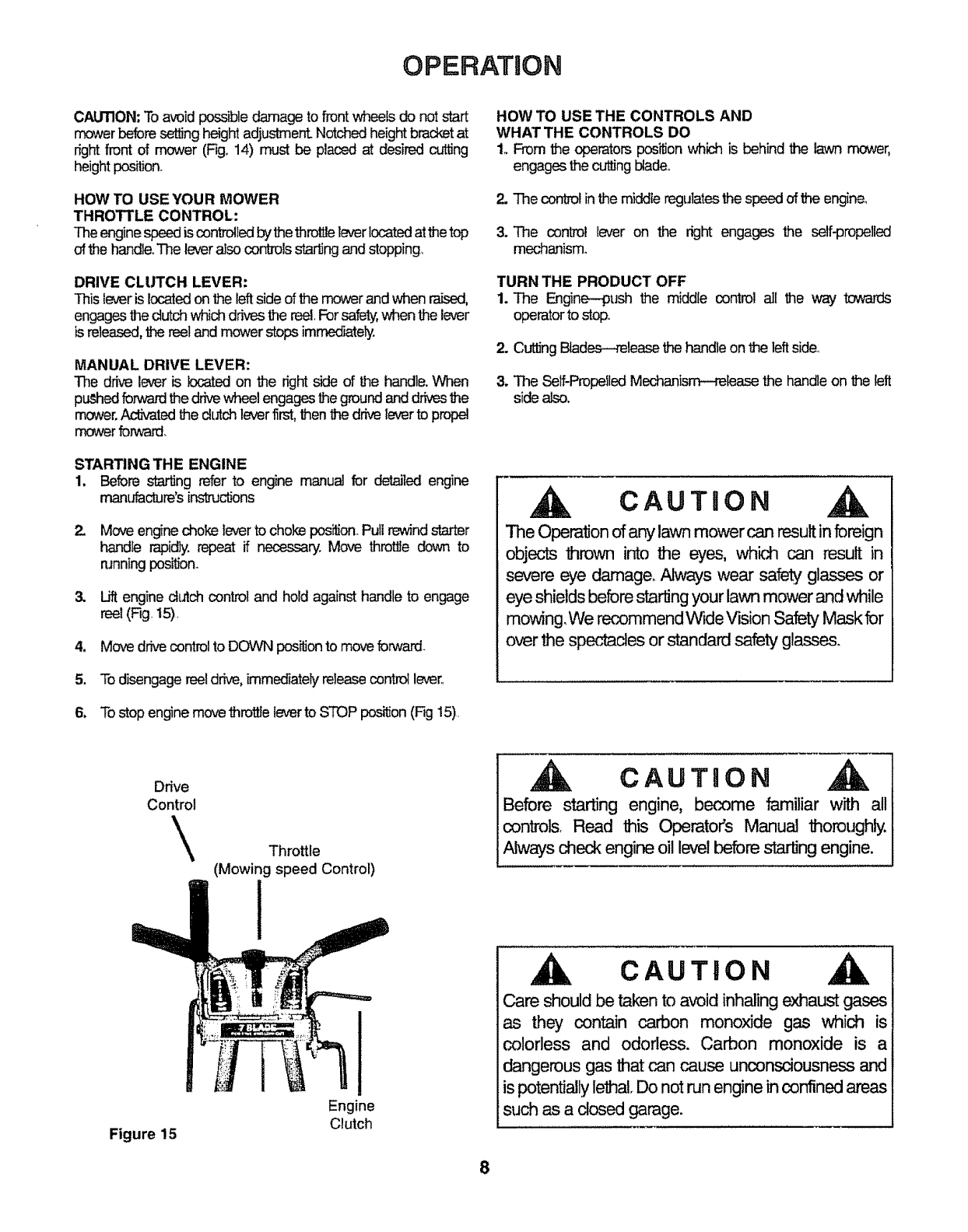
HOW TO USE YOUR MOWER
THROTTLE CONTROL:
Theenginespeed iscontrolledbythe throttleleverlocatedatthe top
of the handleoTheleveralsocontrols sta_ng andstopping,
DRIVE CLUTCH LEVER:
This leveris locatedon the leftside of the mowerand when raised,
engages the clutch whichdrives thereel,For safety,when the lever
is released,the reeland mower stops immediately.
MANUAL DRIVE LEVER:
The drive lever is located on the right side of the handle. When
pLied forwardthe drivewheelengagesthe groundanddrivesthe
mower.Activatedthe clutch leverfirst,then the drive leverto propel
mowerforward,
STARTING THE ENGINE
1. Before starling refer to engine manual for detailed engine
mant_cture's inst_ctions
2. Move enginechoke lever to chokeposi_on.Pull rewindstarter
handle rapidly,repeat if necessary, Move throttledown to
runningposition.
& Lift engine dutch control and hold against handle to engage
reel (Fig.t5)
4. Move drivecontrolto DOWN positiontomove forward
5. To disengage ree!drive,immediatelyreleasecontrollever.
6, To stop enginemovethrotUeleverto STOP position(Fig 15)
HOW TO USE THE CONTROLS AND
WHAT THE CONTROLS DO
1. From the operators pos_onwhich is behind the lawn mower,
engages the cuttingblade.
2. The controlin the middle regulatesthe speed of the engine,
3. The control lever on the right engages the self-propelled
mechanism.
TURN THE PRODUCT OFF
1. The Engine--gush the middle control all the way towards
operatorto stop
2. Cutting Blades--._leese the handleon the leftside.
3. The Self-PropelledMechanism--release the handleon the left
side also.
CAUTHON
The Operation of any lawn mower can result in foreign
objects thrown into the eyes, which can result in
severe eye damage, Always wear safety glasses or
eye shields before starting your lawn mower and while
mowing. We recommend Wide Vision Safety Mask for
over the spectacles or standard safety glasses.
Drive
Control
\Throttle
(Mowing speed Control)
CAUTHON
Before starting engine, become familiar with all
controls. Read this Operator's Manual thoroughly.
Always check engine oil level before starting engine.
Figure 15
Engine
Clutch
CAUTION
Care should be taken to avoid inhaling exhaust gases
as they contain carbon monoxide gas which is
colorless and odorless. Carbon monoxide is a
dangerous gas that can cause unconsciousness and
is potentially lethal Do not run engine in confined areas
such as a dosed garage.
8

MARNTENANCE
GENERAL RECOMMENDATION
1. The spark plug and air filtershould be
replaced once a year,This will assure
better engine performance and longer
engine lifeo
2. Check allfastenersand be surethey are
light
& Follow all maintenance insb-dctions
listed on the following pages an the
service _ule
CAUTION
DISCONNECT SPARK LUG WIRE FROM
SPARKPLUG AND PLACEWIREWHERE
1T CANNOT COME IN CONTACT WiTH
SPARK PLUG.
AIR CLEANER
COVER OILFILLPUJG
OIL LEVER
RGURE 16
CHANGING ENGINE OIL
1. Tiltmowerback, placesuitablecontainer
on floor nextto drive wheel.
2.. Place a piece of metalover drive wheel
so oil will drain into container.A plastic
funnel can also be used. Cut part of
funnel away and place under drainplug
making sure small end of funnel is
directedtoward the container,.
3. Removeoildrain plug.(Referto Fig.16).,
4. When oil is drained, replace plug and
refill crankcase W_ oil as per
ins-_Jctionson page 7.,
TO SERVICE AIR CLEANERS
Clean cartridge at three month intervalsor
every25 hours,whicheveroccursfirst,
NOTE: Service more often if necessary.
1. Remove knob and cover,
2. Remove cartridge by pulling it off of the
SCt_,
3. Clean bylapping gentlyona flatsurface.
tfvery dirty,replacecartridgeor clean as
follows:
a. Wash in a low or non-sudsing
detergent and warm water solution,
CAbTION: Do not use petroleum
solvents such as kerosene, to clean
cartridge
b. Rinse thoroughly with flowing water
from inside out untilwater is dear.
c. Allow cartridgeto stand and airdry
thoroughlybefore using
DO NOT OIL CARTRIDGE
DONOTUSEPRESSURIZF.JDAIR
10 CLEANORDRYCAm'RIDGE
4. Install cartridge, then cover and screw
knob securely See Figure 17,
KNOB -..-,.-,-.-=_ _
CARTRIDGE
RGURE 17
SPARK PLUG
Clean and reset gap at O30" every 100
hoursofoperation
CLEAN COOUNG SYSTEM
Grass, chaff or dirt may clog the rotating
screen and the air cooling system
especially after prolonged service cutting
dry grass. Yearly or every 100 hours,
whichever occursfirst, removethe blower
housing and clean the areas to avoid over
speeding, overheating and engine
damage. Clean more often if necessary.
REfer to Engine manual for detailed
in_uclion&
CLEAN ENGINE
Remove dirt and debris with a cloth or
brush° Cleaning with a force_JIspray of
water is not recommended as water could
contaminatethe fuel
9
LUBRICATION
Check oil level regularly.Oil all exposed
bearings,linageand front wheels.Oilchain
frequently,Reef and main drive bearings
are sealed,
REEL MAINTENANCE
Normally grinding of the reel is not
recommended or necessary to insure
proper cuWng This is due to the extreme
hardnessand great strength of the reelo
Sharpening and back lapping when
required, should always be done by a
properlyequipped ser_cecenter.
ADJUSTMENTS
CAUTION: DO NOT RUN ENGINE AT
EXCESSIVE SPEEDS Operating an
engine at excessive speeds increasesthe
dangerof persona]injury.
1. DO N,Jrqr'TAMPER WITH GO#ERt',,OR
SPRINGS, G_#ERNOR UNKS OR
OTHERPAR_ WHICHMAYINCREASE
THEGOVERNEDENGINESPEED
TO CHECK OPERATION OF CHOKE
CONTROLS:
Move speed control lever to "choke"
posilionoThe carburetor choke should be
closed.
"A" "A"
BV_
STOP
SWITCH
RGURE 17
CHOKE
CLOSED

SERVICE AND ADJUSTMENTS
TO ADJUST CHOKE CONTROLS:
Refer to engine manual for detailed
instnJc_ons.
REPLACE AIR CLEANER.
Clipfor throtilecableshouldsecurecable to
handle,
CARBURETOR ADJUSTMEWfS
Minor carburetor adjustment may be
requiredto compensatefor differencesin
fue!, temperature, altitude or load, Air
cleaner and air deaner cover must be
assembled to carburetor when running
engine
1_31ALADJUSTMF_,l'r:
GentJylum needle valve ctodwviseuntil it
just doses. Va_/e rr_.€ be damaged by
turning it intoo faro(Referto F_j.19).
Next open needle valve 1-1/2 tums
counte_odewise,Thisinitbladjustmentwill
permit the engine to be started and
warmed up (app_ 5minutes)prior
tofinal adjustment.
CARBURETOR ADJUS'rM£_ RGURE 19
RNAL/_U,_EI_:
Place th@ controlin 'T-AST"position°
Turn needle valve in u_l engine slows
(clode,4.seqeanmixture)°Then turn it out
past smooth operating point until engine
runs u_ty (rich mixture). N_v turn
needle vak,e to 1hemidpointbetweenrich
and leansothe engine runssmoothly.Next,
adjust idle RPM Rotate throttle
cc,Jnte_ ar_ hold against stop
whileadjtL_ngidlespeedadjustingscrew
to obtain 1750 RPMo Release throt_.
Engineshouldacceleratev,_out _n
or sputtering,, If it does not, caff:_retor
should be readjlL_,_d,u_._fy to a sr_t_y
richermixture.
CLUTCH BELT MAINTENANCE:
1. Inspectdutch beltfrequencyforwear
and damage.Wornand damaged
beltscancausethe dutch to operate
improperly,suchas con_nuous
movementofthe reeland rollerdn've
whenail leversare disengaged
Replacethe belt whenexcessivewear
or damage occurs,
CLUTCH BEL'rREPLACEMENT:
1. Removecotterpin from lowerdutch
cc_'d_l rod (Part 1012D)and slide
control rodfrom dutch bearing
(Part 1046D)
2. Remove belt guardbolt using 1/2'
wrench and removebelt guardfrom
the dutch body.
3.DetachDeadrr_Uutchsp_ng(Pa_.
1052D) from deadman belt idler
(Part 1047D)_
4. Rernov_thewom belt
5a installnew belt by placingaround
jackshattpulley(Part t053) firstand
then aroundthe enginepuIley
(Part 1063).
6. CAUTION: Make sure idlerbeating
(Part 1048D) restsagainstthe insideof
the belL,(Thebelt must be placed over
the pulleysand the idlerbearing).
7. Replace deadman dutch spring.
(Attachtobeltk_er).
8. Replacebeltguardand beltguardbolt.
Do not _ghtenbolt,
9. Replacedutch controlrodrnakjngsure
rod is placed outsideof _ bell
10, Replacecotter pin and checkbr
proper tensionby followingins_clJons
on page4 under heading=Engine
Clutch RodTensionAdj_
11. Now check dutch beltguard forproper
adjL_alqent There mustbe 1/16"
clearancebetweenthe top of the belt
and_ bottomofthe belt guard.Adjust
guardup or down to maintainthe 1/16"
clearance.
NOTE: The deam:mcemust be checked
and adjustment made when the dutch is
engaged and _hereis tensionon the bee
(Lift dutch lever to the handle to engage
dutch and put tensionon the belt).
12 When the 1116"dearance is achieved,
tightenbolt guard firmly
IMPORTANT:
IMPROPER ADJUSTMENT
OF BELT GUARD AND
TENSION OF CLUTCH
CONTROL ROD CAN CAUSE
PREMATURE WEAR OF THE
BELT AND FAILURE OF
PROPER CLUTCH ACTION.
10

TROUBLE SHOOTnNG CHART
PROBLEM CAUSE
1. Engine fails to start. ACheck fuel tank for gas,,
BSpark plug lead wire disconnected.
C Throttle control lever not in starting posttion_
DCheck spark plug_
ECarburetor improperly adjusted. Engine flooded, Remove
spark plug, dry the plug, crank engine with plug removed,
and throttle in off position,, Replace spark plug and lead wire
and resume starting procedures
F Old/stale gas. Drain and refill with fresh gas,,
2. Hard starting or loss of power. ASpark plug wire loose
BCarburetor improperly adjusted.
C Dirty air cleaner.
3. Operation erratic, ADirt in gas tank. Drain, clean and refill
BDirty air cleaner.
CWater in fuel supply,, Drain and refill
DVent in gas cap and/or carburetor plugged_ Clear vent,
ECarburetor improperly adjusted_
4. Occasional skip (hesitates) at high speed. ASpark plug fouled, faulty or gap too wide.
BCarburetor improperly adjusted.
CDirty air cleaner,
5. Idles poorly. ACarburetor idle speed too slow,
BSpark plug gap too close,
CCarburetor idle mixture adjustment improperly set.,
6. Engine overheats AAdjust carburetor.,
BRemove any obstructions from air passages in shrouds,
CClean cooling fins,
DFill crankcase to proper oil level
NOTICETO CUSTOMERSIN THESTATEOFCALIFORNIA.
THEENGINEONTHIS UNIT IS NOTEQUIPPEDWITH A SPARKARRESTINGMUFFLER.
--WARNING
USE OR OPERTIOHOF THIS ENGINE ON ANY FOREST COVEREDjBRUSH COVERED_OR GRASS COVEREDLAND WITHOUT A STATE
APPROVEDSPARKARRESTORIH EFFECTIVEWORKINGORDERCONSTITtRESA VIOLATIONOF THE LAW OF THE STATEOF CALIFORNIA,
NOTE:For repairs beyondthe minor adjustments listed above,
please contact your local Lawn Mower ServiceCenter
For engine Service see AuthorizedBriggs& Stratton Service Center.
Refer to the Briggs& Stratton EngineManual enclosed.
11
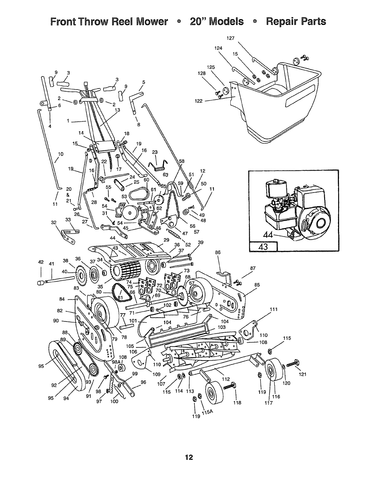
Front Throw ReeaMower o 20" IVlodeas oRepair Parts
127
124
4
10
/
/
11
42 41
l
I
14
20
&
2k
33
38 \
83
84
82
90
3
19
_6 23
44
35
78
105
1
29
104
125
122
12
11
/
56
57
36 52 39
BB
104
103
94 91 97 lOO
96 107
115 t14 113
1!9
112
87
85
111
_} 121
t20
t119 116
118 t17
12

McLane
Front Throw ReeMMower Repair Parts 20"
RER PART RER PART
DESCRIPTION DESCRIPTION
Models
NO, NO.
1 1001-A
2 7015-A
31003
4 1004
5 1005-D
71007
8 1008
9 1009
10 t010
11 I011
!2 I012-D
13 1013-97
14 t014
15 1015
16 1016
18 10t8
19 10!9
20 1020
21 1015
22 1022
23 t023
24 1024
25 1025
26 1026
27 1011
28 1028
29 1029
30 1030
31 !031
32 1032
33 1033
34 1034
35 1035
36 1036
37 I037
38 1038
39 1039
40 1015
4t !041
42 1042
43 1043-A
44 1044
45 !045-D
46 1046-D
47 1047-D
48 1048-D
49 1049
50 7015-A
51 1051
52 1052-D
53 t053
54 !054
55 1028
56 1092
57 1057
58 1058
Handle
Shoulder Bolt for Handle
Handle Grips (2 req,,)
Drive Control Lever
Clutch Control Lever
Plastic Washer (2 req.,) L& R
*Lock Nuts 7/16" - 14 (2 req,) L & R
Drive & Clutch Lever Grips
Drive Contro! Rod
*Cotter Pins 1/8" x 1/2" (3 req )
Clutch Control Rod
Throttle Control-Manual Choke
Handle Brace Plate
"1/4" -28 Nuts (6 req.)
Lower Handle (2 req.)
"1/4 - 28 x 7/8" Bolts (6 req)
Handle Brace (2 req,) L & R
"1/4 - 28 x 5/8" Bolts (2 req ) L & R
"1/4"- 28 Nuts (2 req) L & R
Drive Pivot Rod
Drive Pivot Spring
Drive Pivot Arm
*Set Screw 3/8" -16 x 1/2" Square Head
Lower Drive control Rod
*Cotter Pin 1/8" x 1/2"
"5/16" - 18 x 3/#' Bolts (4 req,) L & R
Deck
Handie Brackets (2 req)
Roller Support Bracket with Bearing
Roller Support Bracket
%/16" - 18 x 1/2°'Bolts (2 req )
Roller Drive Tube
Roller Drive Tires (5 req,)
Roller End Caps (2 req,)
Ind Cap Bearings (2 req_)
Roller Drive Sprocket (30 teeth)
Roller Drive Bolts (3 req)
"1/4"- 28 Drive Nuts (6 reqo)
Roller Drive Shaft
Spacer
Engine, State Model
"5/16"- 24 x 1-1/2" Bolts (4 req)
Main Clutch Body
Clutch Rod Bearing
Belt Idler Arm
Idler Bearing
"3/8"-16 1/2" Flat Head Phillips Head Screw
Bolt for Clutch Body
Washer
Clutch Spring w/Spring Ptate
Jack Shaft with Pulley & Sprocket
Jack Shaft Housing (2 req)
"5116" - !8 x 3/4" Bolts (4 req,)
Clutch Drive Chain -No. 41 x 46 Pitch
*Connecting Link for NoA1 Chain
Clutch Chain Guard
NO.
59
60
61
62
63
64
65
66
67
68
69
70
71
72
73
74
75
76
77
78
79
8O
81
82
83
84
85
86
87
88
89
90
91
92
93
94
95
96
97
98
98A
99
100
101
102
103
t04
105
106
107
13
NO,
1033
t060-B
1061
1062
1063
1064
1065
1066-D
1067-D
1068
1069
1070
1071
1072
1073
1074
1075
1076-P
1077_P
1078-S
6058
1037-D
!080
1057
5001
1083
1028
5002
1086
1028
1088
1070
1033
1091-A
1092
1057
1094
1033
1096
1097
7050
1075-A
t099
1100
1101-2
1101-A
1033
1103-A
1028
1105
I106
1107
"5/16" - 18 x 1/2" Bolts
Clutch Belt
Belt Guard
%/16" - 18 x 3/8" Bolts
Engine Pulley
*Key For Engine Pulley Shaft 3/16"x3/16"x5/8"
Allen Set Screw 5/16" - 24 x 15/16"
Rear Axle Shaft
Retainer
Sprocket (30 teeth with Hub)
Sprocket (8 teeth with Hub)
*Set Screws 7/16" - 20 x 7/16" Half Dog (3 req)
Axle Support Bearing (2 req)
Roller Bracket Supports (2 req )
Axle hangers (4 req)
"Hanger Bolts 5/16" - 24 x 7/8" (8 req)
"5/16" - 24 Nuts (8 req,)
Spacer
Spacer
Rear Wheels w/Bearings (2 reqo)
Bearing For 1078-S
Retainer Bearing
*Roller Drive Chain No, 4!_36 Pitch
*Connecting Link No 41
Slide Plate w/Chain Guard Bracket
Catcher Hook Bracket
"5/16" - I8 x 3/4" Bolts (4 req )
Side Plate
Catcher Hook Bracket
"5/16" - 18 x 3/4" Bolts (4 req,)
Sprocket (17 teeth)
*Set Screws 7/16" -20 x 7/16" Half Dog (4 reqo)
'5/16" - 18 x 1/2" Bolts (2 req )
Sprocket (13 teeth)
"Reel Drive Chain No, 41-46 Pitch
*Connecting Link No, 41
Chain Guard
"5/16" -18 x 1/2" Bolts (2 req,)
Height Adjustment Lever
Height Adjustment Notched Bracket
"5/16 "_ 18 x 3/4" Bolt
5/16"-18 Nut
Spacer Bushing
Height Adjustment Spring
Shield
Shield Assembly Hardware
"5116" -18 x 1/2" Bolt (2 req)
Bed Knife
"5/16"- 18 x 3/4" Belts (2 req,)
Tapered Bolts 5/16" -18 x 5/8" (6 req)
Bushing for Tapered Bolt (6 req)
Reel Assembly 7 Blade
*Standard Hardware items, may be purchased locally.
** NOT SHOWN
NicLane
Front Throw ReeWMower Repair Parts 20" Models (Continued)
REFoPART REF. PART
DESCRIPTION DESCRIPTION
NO, NO.
108 1108
109 1109
110 1033
111 1111
1t2 1112
113 1113
114 t007
t15 1008
115A 1008-A
116 11t6
117 1002
118 1118
119 1008
Reel Bearings (2 req,)
Reel Bearing Retainer
"5/16" - 18 x 1/2" Bolts (2 req,,)
Reel Bearing Retainer
Front Wheel Assembly Bar
Tie rod
Plastic Washer
"7/16"- 14 Nuts (2 req)
"7/16" - 14 Jam Nuts (2 req ,)
Front Wheels with Bearings
Front Wheel Bearings (2 req,)
"7/16" -14 x 3-I/2" Bolt
"7/16"- 14 Nuts (2 req,)
NO. NO.
120 ! 120 Flat Washer
t21 1121 "7/16" -,t4 x3-1/4" Bolt
122 1122 Plastic Grass Catcher
t24 1124 Catcher Hook
125 3065 Washer
t27 1127 Catcher Hook
128 1028 1/4"- 28 x 7/8" Bolt (4 req,)
N/S 3122"* Owner manual--Repair Parts
N/S 1202E** Engine Operating Instruction Manual
*Standard Hardwareitems, may be purchased locally.
** NOT SHOWN
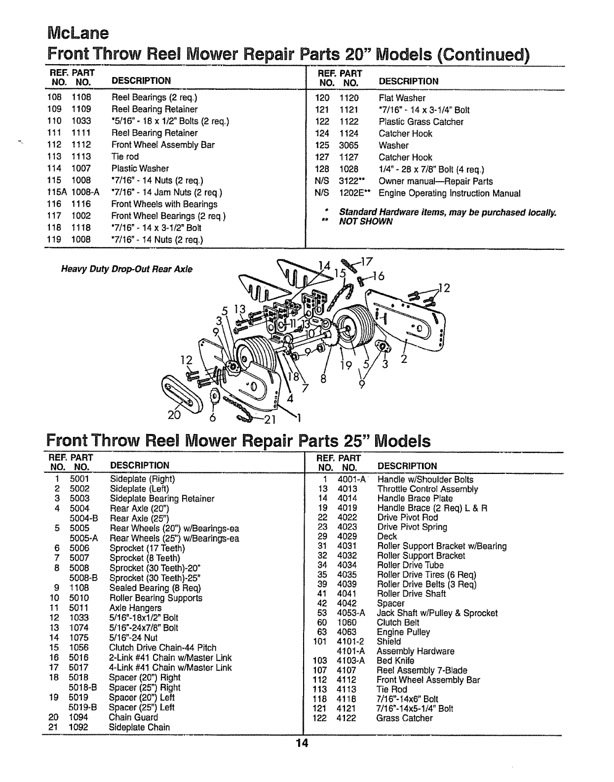
Heavy Duty DropOut Rear Axle
51
!2 2
20 6
4
9
Front Throw Reel Mower Repair Parts 25"
REFoPART REF, PART
DESCRIPTION DESCRIPTION
NO.
1
2
3
4
5
6
7
8
9
10
11
12
!3
14
15
16
t7
18
lg
NO.
5001
5002
5003
5004
5004-B
50O5
5005-A
5006
5007
5008
5008-B
1108
5010
5011
!033
1074
1075
1056
5016
5017
5018
50t8-B
5019
5019-B
1094
1092
Models
Sideplate (Right)
Sideplate (Left)
Sideplate Bearing Retainer
Rear Axle (20")
Rear Axte (25")
Rear Wheels (20") wiBearings-ea
Rear Wheels (25") w/Bearings-ea
20
21
Sprocket (17 Teeth)
Sprocket (8 Teeth)
Sprocket (30 Teeth)-20"
Sprocket (30 Teeth)-25"
Sealed Bearing (8 Req)
Roller Bearing Supports
Axle Hangers
5/16"-18xl/2" Bolt
5/16"-24x7/8" Bolt
5/16"-24 Nut
Clutch Drive Chain-44 Pitch
2-Link #41 Chain w/Master Unk
4-Link #41 Chain w/Master Link
Spacer (20") Right
Spacer (25") Right
Spacer (20") Left
Spacer (25") Left
Chain Guard
Sidepiate Chain
NO. NO.
1 4001-A
13 4013
14 4014
19 4019
22 4022
23 4023
29 4029
31 4031
32 4032
34 4034
35 4035
39 4039
41 404t
42 4042
53 4053-A
60 1060
63 4063
101 4101-2
4t01-A
103 4103-A
107 4107
112 4112
!13 4113
118 4!18
121 4121
122 4122
Handle w/Shoulder Bolts
Throttle Conlrot Assembly
Handle Brace Plate
Handle Brace (2 Req) L & R
Drive Pivot Rod
Drive Pivot Spring
Deck
Roller Support Bracket w/Bearing
Roller Support Bracket
Roller Drive Tube
Roller Drive Tires (6 Req)
Roller Drive Belts (3 Req)
Roller Drive Shaft
Spacer
Jack Shaft w/Pulley & Sprocket
Clutch Belt
Engine Pulley
Shield
Assembly Hardware
Bed Knife
Reel Assembly 7-Blade
Front Wheel Assembly Bar
Tie Rod
7/16"-t4x6" Bolt
7/16"-I4x5-1/4" Bolt
Grass Catcher
14

STORAGE
MOWER:
oClean all debris off mower and engine with a rag or
brush..
*Do not use water.
. Oil all chains and wipe off excess oil with a rag..
ENGINE:
Engines to be stored over 30 days should be completely
drained of fuel to prevent gum deposits forming on
essential carburetor parts, fuel filter and tank_
NOTE:
The useof a fuel additive, such as STA-BIL®,or an equivalent,
will minimize the formation of fuel gum deposits during
storage. Such an additive may be added to the gasoline in
the fuel tank of the engine, or to the gasoline in a storage
container.
a, All fuel should be removed from the tank. Run the
engine until it stops from lack of fuel.
b. While engine is still warm, drain oil from crankcase°
Refill with fresh oil,
c. Remove spark plug,pour approximately 1/2 ounce (15 cc)
of engine oil into cylinder and crank slowly to distributeoil
Replace spark plug..
d. Clean dirt and chaff from cylinder, cylinder head fins,
-blower housing, rotating screen and muffler areas°
e. Store in a clean and dry area°
IMPORTANT:
1T IS IMPORTANT TO PREVENT GUM DEPOSITS
FROM FORMING IN ESSENTIAL FUEL SYSTEM
PARTS SUCH AS THE CARBURETOR, FUEL FILTER,
FUEL HOSE, OR TANK DURING STORAGE.. ALSO,
EXPERIENCE INDICATES THAT ALCOHOL BLENDED
FUELS (CALLED GASOHOL OR USING ETHANOL OR
METHANOL) CAN ATTRACT MOISTURE WHICH
LEADS TO SEPARATION AND FORMATION OF ACIDS
DURING STORAGE. ACIDIC GAS CAN DAMAGE THE
FUEL SYSTEM OF AN ENGINE WHILE IN STORAGE°
OTHER:
Do not store gasoline from one season to another.
•Replace your gasoline can if your can starts to rust.
Rust and/or dirt in your gasoline can cause problems_
.Do not store your mower under any plastic cover.
Plastic cannot breathe which allows condensation to
form and can cause your mower to rust.
SERVICE RECOMMENDATIONS
SERVICE RECORD
|
ENGINE OIL CHANGE
ENGINE OIL CHECK
SERVICE AIR CLEANER
CLEAN/REPLACE SPARK PLUG
LUBRICATE MOWER
CHECK MUFFLER
CLEAN MOWER
SCHEDULE
RsT EVEm'EVERY
5 25 50
HOURS HOURS HOURS
XX
X
EVERY
100 HRS.
OR SEASON
X
X
X
EVERY
USE
X
X
SERVICE DATES
RLL IN WHEN SERVICE
IS COMPI.ETED
•| i •
15

NOTES--. MAINTENANCE RECORD
16
