MediaTek RT3090BC4 802.11b/g/n 1T1R combo card User Manual WM5200 MNL English F 0 7
MediaTek Inc. 802.11b/g/n 1T1R combo card WM5200 MNL English F 0 7
UserManual.wiki
>
MediaTek
>
RT3090BC4 User Manual
>
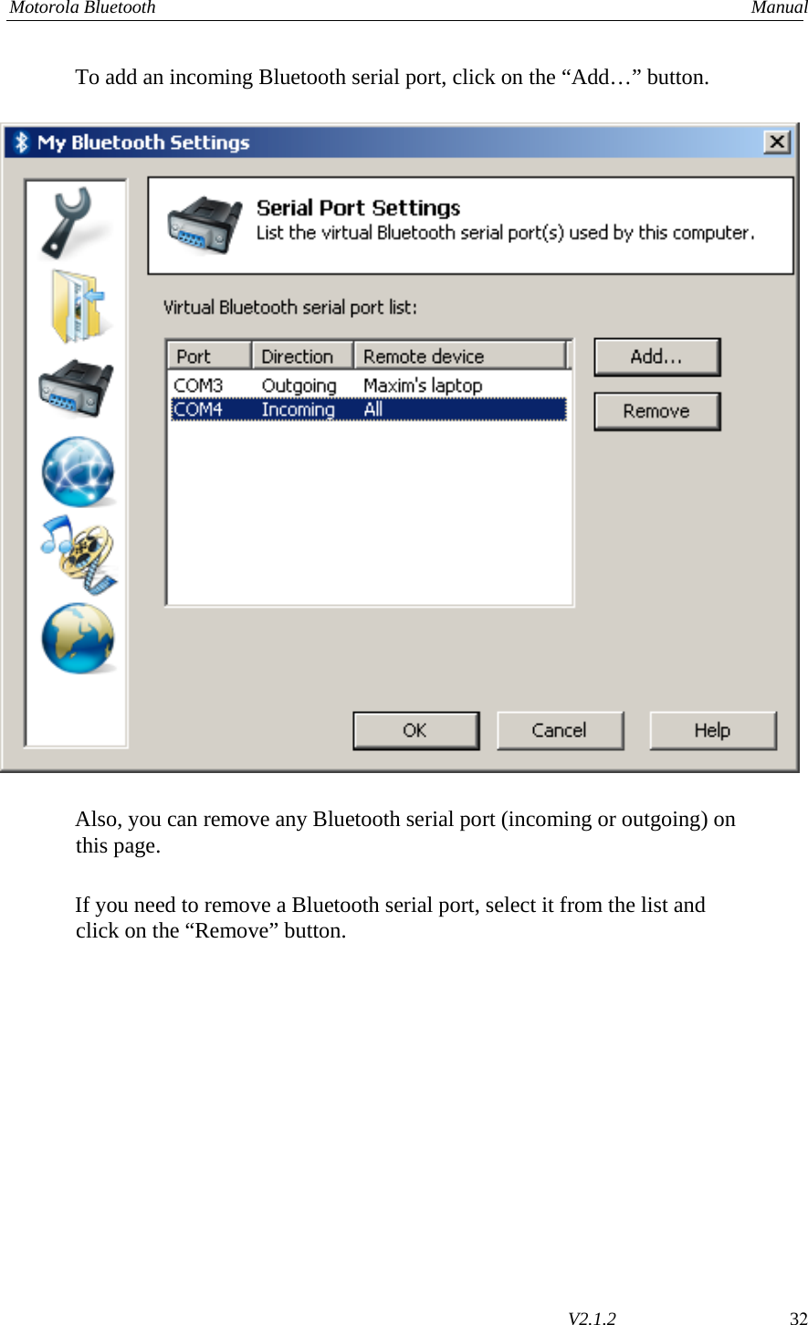
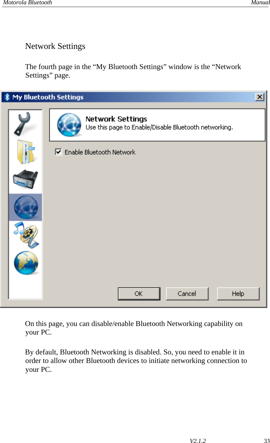
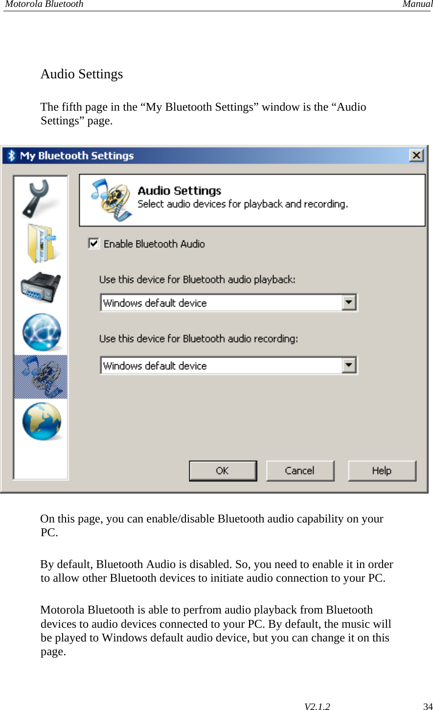
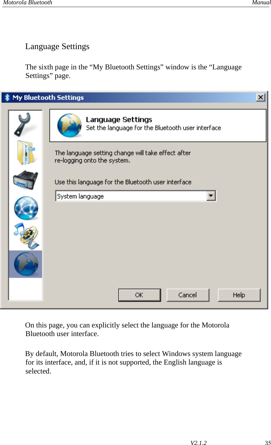
User Manual
Contents
1.
User Manual
2.
User manual
3.
Regulatory statement
4.
OEM installation guide
5.
User Manual 1
6.
User Manual 2
7.
Warning Statements in Users Manual
8.
Warning Statements for Users Manual
9.
USERS MANUAL
10.
USER MANUAL
11.
Users Manual (1)
12.
Users Manual (2)
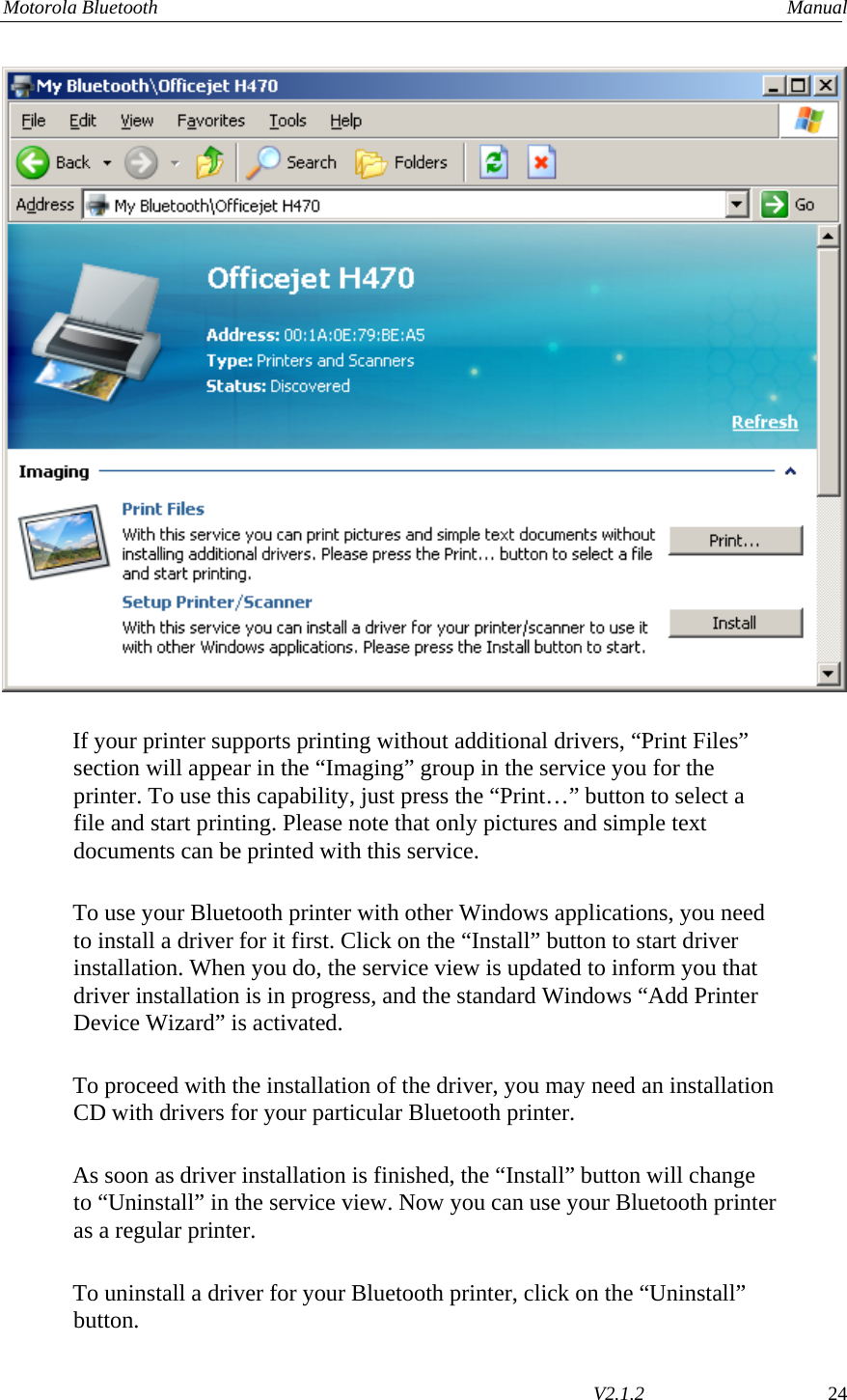
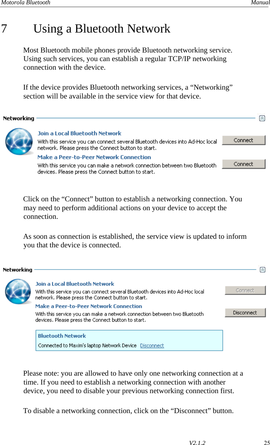
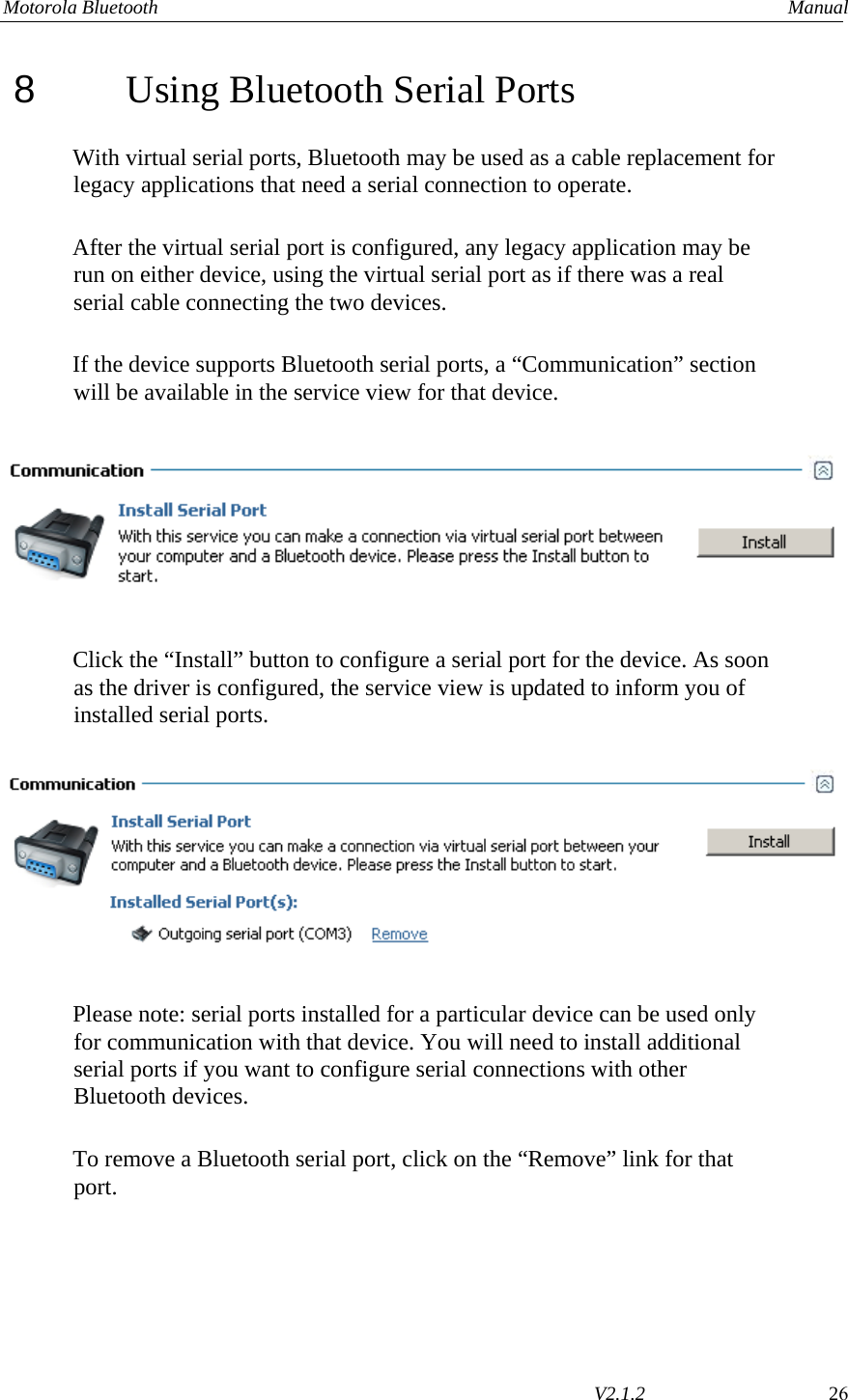
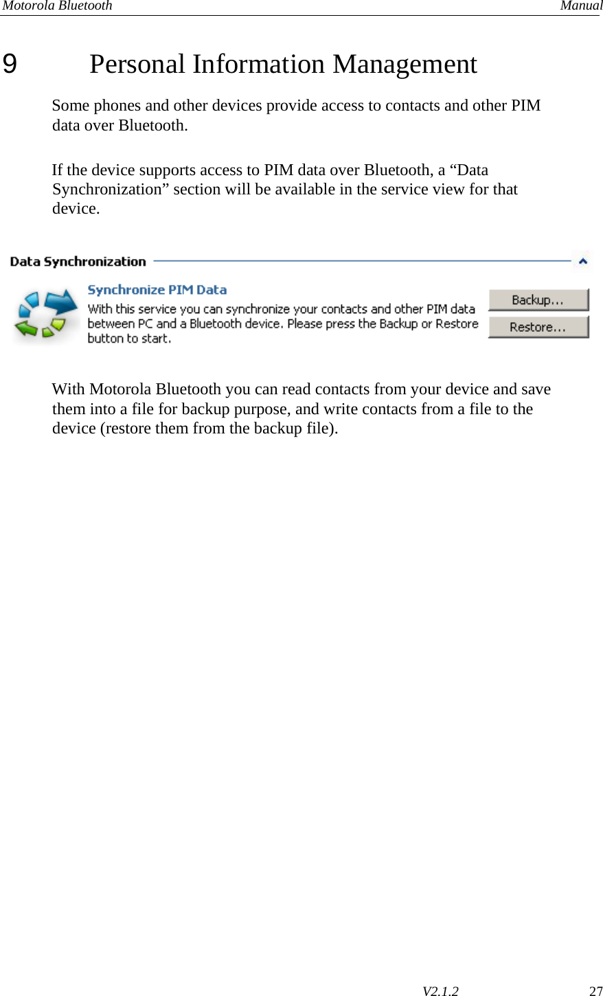
User Manual
Navigation menu
Upload a User Manual
Namespaces
Wiki Guide
HTML
PDF
Info
Views
User Manual
Discussion / Help
Navigation