MediaTek RT3090BC4 802.11b/g/n 1T1R combo card User Manual WM5200 MNL English F 0 7
MediaTek Inc. 802.11b/g/n 1T1R combo card WM5200 MNL English F 0 7
MediaTek >
Contents
User Manual
802.11n compliant 2.4GHz
Mini-PCI Module
User’s Manual
11b/g/n 1T1R WLAN Mini Card
RT3090BC4
Ralink
REGULATORY STATEMENTS
FCC Certification
The United States Federal Communication Commission (FCC) and the
Canadian Department of Communications have established certain rules
governing the use of electronic equipment.
Part15, Class B
This device complies with Part 15 of FCC rules. Operation is subject to the
following two conditions:
1) This device may not cause harmful interference, and
2) This device must accept any interference received, including interference
that may cause undesired operation. This equipment has been tested and
found to comply with the limits for a Class B digital device, pursuant to Part
15 of the FCC Rules. These limits are designed to provide reasonable
protection against harmful interference in a residential installation. This
equipment generates, uses and can radiate radio frequency energy, and if not
installed and used in accordance with the instructions, may cause harmful
interference to radio communications. However, there is no guarantee that
interference will not occur in a particular installation. If this equipment does
cause harmful interference to radio or television reception, which can be
determined by turning off and on, the user is encouraged to try to correct the
interference by one or more of the following measures:
• Reorient or relocate the receiving antenna.
• Increase the separation between the equipment and receiver.
• Connect the equipment into an outlet on a circuit different from that
to which the receiver is connected.
• Consult the dealer or an experienced radio/TV technician for help.

Warning: Changes or modifications to this unit not expressly approved by
the party responsible for compliance could void the user authority to
operate the equipment.
CAUTION
1. This Transmitter must not be co-located or operating in conjunction with
any other antenna or transmitter.
2. For product available in the USA market, only channel 1~11 can be
operated. Selection of other channels is not possible.
Agency in the United States of America:
Company Name: Xterasys Corporation
Tel: 909-590-0600 Fax: 909-590-0388
Address: 4711 CHINO AVE. CHINO, CA91710
IMPORTANT NOTE:
This module is intended for OEM integrator. The OEM integrator is still
responsible for the FCC compliance requirement of the end product, which
integrates this module.
20cm minimum distance has to be able to be maintained between the antenna
and the users for the host this module is integrated into. Under such
configuration, the FCC radiation exposure limits set forth for an
population/uncontrolled environment can be satisfied.
Any changes or modifications not expressly approved by the manufacturer
could void the user's authority to operate this equipment.
USERS MANUAL OF THE END PRODUCT:
In the users manual of the end product, the end user has to be informed to keep
at least 20cm separation with the antenna while this end product is installed and
operated. The end user has to be informed that the FCC radio-frequency
exposure guidelines for an uncontrolled environment can be satisfied. The end
user has to also be informed that any changes or modifications not expressly
approved by the manufacturer could void the user's authority to operate this
equipment. If the size of the end product is smaller than 8x10cm, then
additional FCC part 15.19 statement is required to be available in the users
manual: This device complies with Part 15 of FCC rules. Operation is subject
to the following two conditions: (1) this device may not cause harmful
interference and (2) this device must accept any interference received,
including interference that may cause undesired operation.
LABEL OF THE END PRODUCT:
The final end product must be labeled in a visible area with the following "
Contains TX FCC ID: VQF-RT2700E ". If the size of the end product is larger
than 8x10cm, then the following FCC part 15.19 statement has to also be
available on the label: This device complies with Part 15 of FCC rules.
Operation is subject to the following two conditions: (1) this device may not
cause harmful interference and (2) this device must accept any interference
received, including interference that may cause undesired operation.
Hereby, Ralink, declares that this device is in compliance with the essential requirement
and other relevant provisions of the R&TTE Driective 1999/5/EC.
VQF-RT3090BC4
Canada IC Statement
IC : 7542A-RT3090BC4
Operation is subject to the following two conditions:
1) this device may not cause interference and
2) this device must accept any interference, including interference that may cause
undesired operation of the device.
IMPORTANT NOTE:
This module is intended for OEM integrator. The OEM integrator is still responsible for
the IC compliance requirement of the end product, which integrates this module.
20cm minimum distance has to be able to be maintained between the antenna and the
users for the host this module is integrated into. Under such configuration, the IC
radiation exposure limits set forth for an population/uncontrolled environment can be
satisfied.
Any changes or modifications not expressly approved by the manufacturer could void
the user's authority to operate this equipment.
This Class B digital apparatus complies with Canadian ICES-003.
Cet appareil numérique de la classe B conforme á la norme NMB-003 du Canada.
USERS MANUAL OF THE END PRODUCT:
In the users manual of the end product, the end user has to be informed to keep at least
20cm separation with the antenna while this end product is installed and operated. The
end user has to be informed that the IC radio-frequency exposure guidelines for an
uncontrolled environment can be satisfied. The end user has to also be informed that any
changes or modifications not expressly approved by the manufacturer could void the
user's authority to operate this equipment.
LABEL OF THE END PRODUCT:
The final end product must be labeled in a visible area with the following
" Contains TX IC: 7542A-RT3090BC4".
Japanese Notice
VCCIの対角線長:4.5mm
認定マークの直徑:5mm
材質 :PVC
地色 :T-02015HB(銀)
印刷色 :Pantone cool gray 11c
粘著材 :アクリル樹脂系糊
認定マークの形狀
0.4A
A
A
0.6A0.4A 0.4A
0.3A
0.5A
0.5A
0.4A
0.4A
0.4A
0.3A
RT3090BC4
N136
FCC ID: VQF-RT3090BC4
IC: 7542A-RT3090BC4
13mm
25mm
XXXXXXXX RAK-RT3090BC4
R XXXXXX
XXXXXX
T XXXXXXX
A=0.83mm
認定マークの直徑=5mm
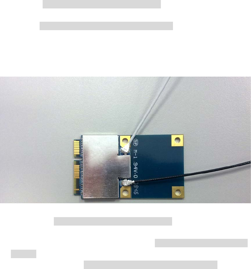
Hardware Quick Installation Guide
Installing the Wireless Mini PCI Express Module
1. Power down the computer.
2. Plug the Wireless PCI Express Minicard Module board to
motherboard minicard slot
3. Connect 2 external antennas used I-PEX connector for WiFi antenna.
4. Power on the computer.
Un-installing the Wireless Mini PCI Express Module
1. Power down the computer
2. Removed 2 external WiFi antennas from the Wireless Mini PCI Express
Module
3. Carefully removed the Wireless PCI Express Minicard Module from the
motherboard minicard slot.
4. Power on the computer.
2 external antennas used I-PEX
connector for WiFi antenna
Table of Contents
INTRODUCTION...................................................................................................1
WIRELESS NETWORK OPTIONS ...............................................................................1
The Peer-to-Peer Network .........................................................................1
The Access Point Network ........................................................................2
SOFTWARE INSTALLATION.............................................................................3
INSTALL THE DEVICE ..............................................................................................3
INSTALL THE DRIVER & UTILITY ............................................................................3
HARDWARE INSTALLATION............................................................................8
VERIFICATION ........................................................................................................8
NETWORK CONNECTION .................................................................................9
IN WINDOWS 2000/ XP ..........................................................................................9
IP ADDRESS .........................................................................................................11
CONFIGURATION UTILITY.............................................................................12
INTELLIGENT WIRELESS UTILITY ..........................................................................13
Profile......................................................................................................13
Network...................................................................................................22
Advanced.................................................................................................27
Statistics...................................................................................................29
WMM / QoS............................................................................................32
WPS.........................................................................................................33
Radio On/Off...........................................................................................36
About.......................................................................................................36
UNINSTALLATION.............................................................................................38
- 1 -
INTRODUCTION
The 11b/g/n 1T1R WLAN Mini Card is a device that allows you
connect your computer to a wireless local area network (LAN). A wireless LAN
allows your system to use wireless Radio Frequency (RF) technology to transmit
and receive data without physically attaching to the network. The Wireless
protocols that come with this product ensure data security and isolation from
interference generated by other radio frequencies.
This card also allows you to take full advantage of your computer’s mobility with
access to real-time information and online services anytime and anywhere. In
addition, this device eliminates the bother of pulling cable through walls and
under furniture. It even allows you to place your system in locations where
cabling is impossible. Modifying and augmenting networks has never been so
easy.
Wireless Network Options
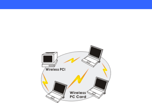
The Peer-to-Peer Network
This network installation lets you set a small wireless workgroup easily and
quickly. Equipped with wireless PC Cards or wireless PCI, you can share files
and printers between each PC and laptop.
- 2 -
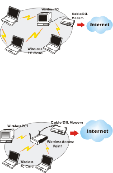
You can also use one computer as an Internet Server to connect to a wired global
network and share files and information with other computers via a wireless LAN.
The Access Point Network
The network installation allows you to share files, printers, and Internet access
much more conveniently. With Wireless LAN Cards, you can connect wireless
LAN to a wired global network via an Access Point.

- 3 -
SOFTWARE INSTALLATION
Install the device
1. Make sure the computer is turned off. Remove the expansion slot
cover from the computer.
2. Carefully slide the 11b/g/n 1T1R WLAN Mini Card
into the mini PCI slot. Push evenly and slowly and ensure it is
properly seated.
3. After the device has been connected to your computer, turn on your
computer. Windows will detect the new hardware and then
automatically copy all of the files needed for networking.
Install the Driver & Utility
1. Exit all Windows programs. Insert the included CD-ROM into your
computer. The CD-ROM will run automatically.
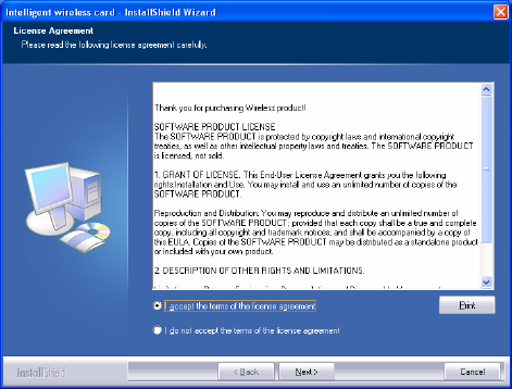
2. When the License Agreement screen appears, please read the
contents and select “I accept the terms of the license agreement
“ then click Next to continue.
- 4 -
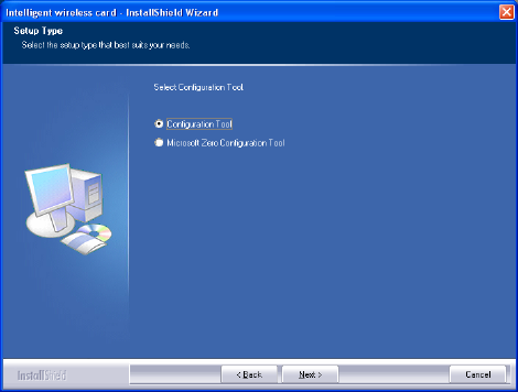
3. Select the check box to choose a Configuration Tool from the listed
two choices.
z Configuration Tool: Choose to use our configuration utility.
z Microsoft Zero Configuration Tool: Choose to use Windows XP’s
built-in Zero Configuration Utility (ZCU).
Click Next to continue.
- 5 -
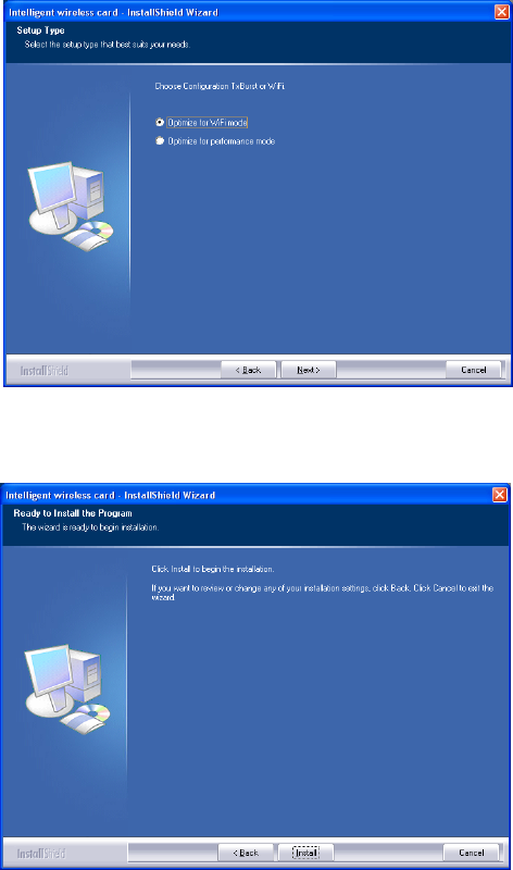
4. There are two modes for you to choose in this screen, either choose
WiFi mode or performance mode (TxBurst mode). This mode
selection screen is set for the default mode shown in the utility screen,
you can still change its mode later in the utility screen. Click Next to
continue.
- 6 -
5. When you are prompted the following message, please click Install
to begin the installation.
- 7 -
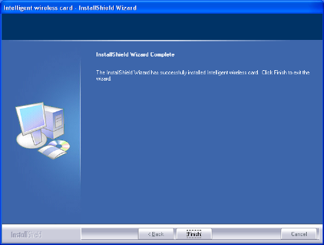
6. When the following screen appears, click Finish to complete the
software installation.
- 8 -
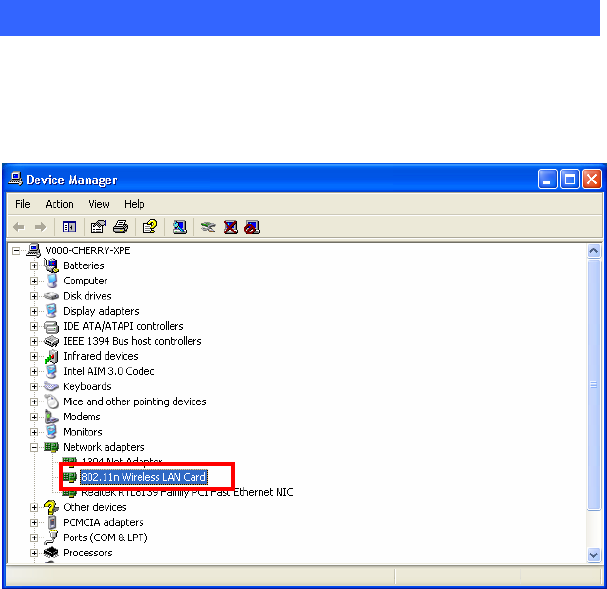
HARDWARE INSTALLATION
Verification
To verify if the device exists in your computer and is enabled, go to Start >
Control Panel > System (> Hardware) > Device Manager. Expand the
Network Adapters category. If the 11b/g/n 1T1R WLAN Half Mini Card
is listed here, it means that your device is properly installed and enabled.
11b/g/n 1T1R WLAN Mini Card
- 9 -
NETWORK CONNECTION
Once the device driver is well installed, a network setting described in the
following should be also established.
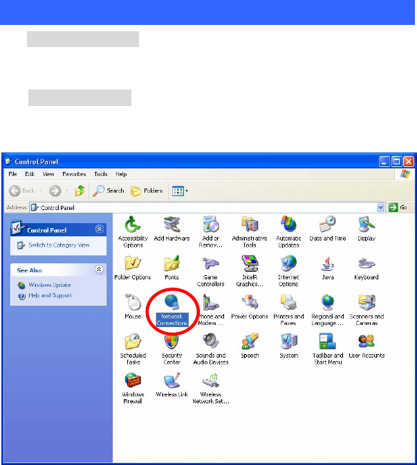
In Windows 2000/ XP
1. (In Windows 2000)
Go to Start Æ Settings Æ Control Panel Æ Network and Dial-up
Connections Æ Local Area Connection Æ Properties.
(In Windows XP)
Go to Start Æ Control Panel Æ Network and Internet Connections Æ
Network Connections Æ Wireless Network Connection Æ Properties.
- 10 -
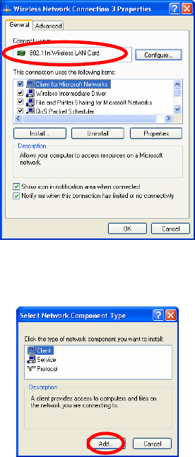
2. Make sure that all the required components are installed.
3. If any components are missing, click on the Install… button to
select the Client/Service/Protocol required. After selecting the
component you need, click Add… to add it in.
4. For making your computer visible on the network, make sure you
have installed File and Printer Sharing for Microsoft Networks.
11b/g/n 1T2R WLAN Mini Card
- 11 -
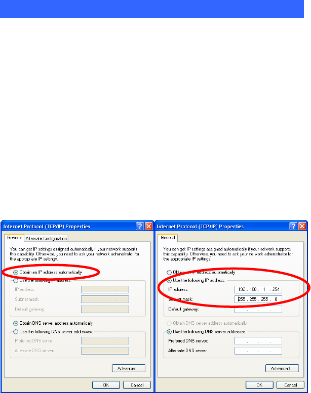
IP Address
Note: When assigning IP Addresses to the computers on the network, remember
to have the IP address for each computer set on the same subnet mask. If your
Broadband Router use DHCP technology, however, it won’t be necessary for you
to assign Static IP Address for your computer.
1. To configure a dynamic IP address (i.e. if your broadband Router has the DHCP
technology), check the Obtain an IP Address Automatically option.
2. To configure a fixed IP address (if you broadband Router is not DHCP
supported, or when you need to assign a static IP address), check the Use the
following IP address option. Then, enter an IP address into the empty field; for
example, enter 192.168.1.254 in the IP address field, and 255.255.255.0 for the
Subnet Mask.
- 12 -
CONFIGURATION UTILITY
After the Wireless adapter has been successfully installed, users can use the
included Configuration Utility to set their preference.
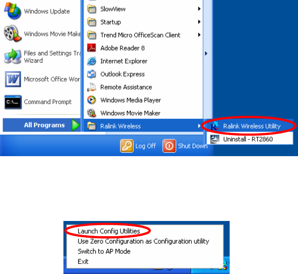
Go to StartJ (All) ProgramsJ Ralink WirelessJ Ralink Wireless Utility.
You can also open the Configuration Utility by double clicking the icon or right
clicking to select Launch Config Utilities.
- 13 -
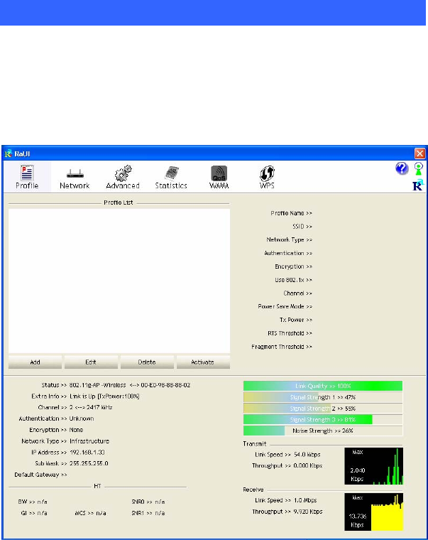
Intelligent Wireless Utility
Profile
Profile can book keeping your favorite wireless setting among your home, office,
and other public hot-spot. You may save multiple profiles, and activate the correct
one at your preference. The Profile manager enables you to Add, Edit, Delete and
Activate profiles.
- 14 -
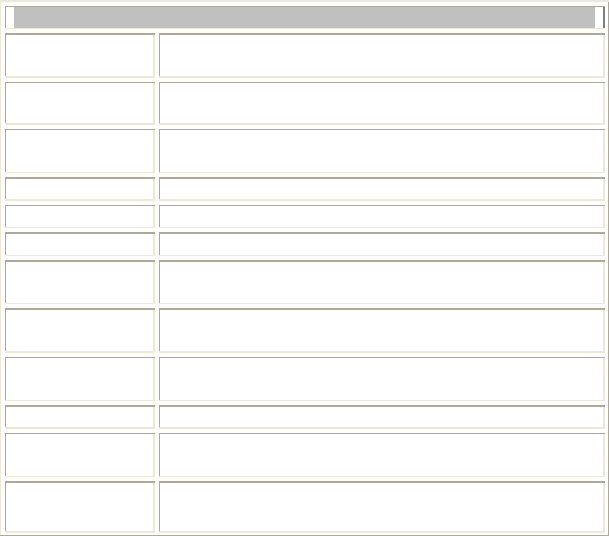
Profile Tab
Profile Name You may enter a distinctive name of profile in this
column. The default is PROF# (# 1, #2, #3....)
SSID The SSID is the unique name shared among all points in
your wireless network.
Network Type Shows the network type of the device, including
infrastructure.
Authentication Shows the authentication mode.
Encryption Shows the encryption type.
Use 802.1x Whether or not use 802.1x feature.
Channel Shows the selected channel that is currently in use. (There
are 13 channels available, depending on the country.)
Power Save
Mode Choose from CAM (Constantly Awake Mode) or Power
Saving Mode.
Tx Power Transmit power, the amount of power used by a radio
transceiver to send the signal out.
RTS Threshold Shows the RTS Threshold of the device.
Fragment
Threshold Shows the Fragment Threshold of the device.
Add Click to add a profile from the drop-down screen.
System Configuration tab:
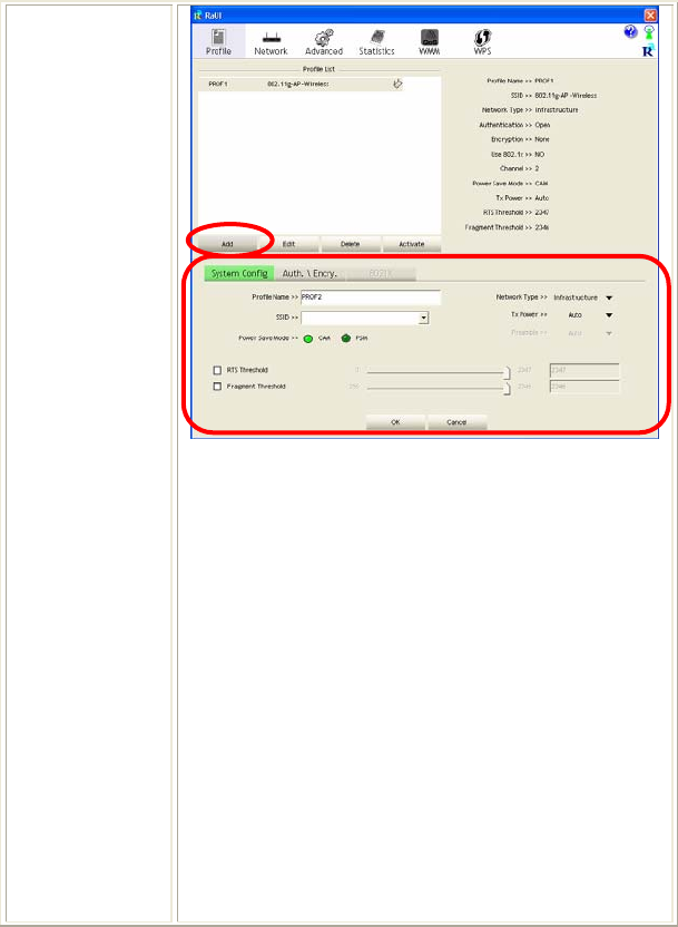
- 15 -
Profile Name: User can enter profile name, or use default
name defined by system. The default is PROF# (# 1, #2,
#3....).
SSID: The SSID is the unique name shared among all
points in your wireless network. The name must be
identical for all devices and points attempting to connect
to the same network. User can use pull-down menu to
select from available APs.
Power Save Mode:
• CAM (Constantly Awake Mode): When this mode is
selected, the power supply will be normally provided
even when there is no throughput.
• PSM (Power Saving Mode): When this mode is
selected, this device will stay in power saving mode
even when there is high volume of throughput.
Network Type: There are two types, infrastructure
modes.

- 16 -
• The infrastructure is intended for the connection
between wireless network cards and an Access Point.
With the wireless adapter, you can connect wireless
LAN to a wired global network via an Access Point.
Tx Power: Select the Tx power percentage from the
pull-down list including Auto, 100%, 75%, 50%, 25%,
10% and Lowest.
Preamble: A preamble is a signal used in wireless
environment to synchronize the transmitting timing
including Synchronization and Start frame delimiter.
Select from the pull-down menu to change the Preamble
type into Auto or Long.
RTS Threshold: User can adjust the RTS threshold
number by sliding the bar or key in the value directly. The
default value is 2347. RTS/CTS Threshold is a
mechanism implemented to prevent the “Hidden Node”
problem. If the “Hidden Node” problem is an issue, users
have to specify the packet size. The RTS/CTS mechanism
will be activated if the data size exceeds the value you set.
This value should remain at its default setting of 2347.
Should you encounter inconsistent data flow, only minor
modifications of this value are recommended.
Fragment Threshold: User can adjust the Fragment
threshold number by sliding the bar or key in the value
directly. The default value is 2346. The mechanism of
Fragmentation Threshold is used to improve the
efficiency when high traffic flows along in the wireless
network. If your Wireless LAN Adapter often transmits
large files in wireless network, you can enter new
Fragment Threshold value to split the packet. The value
can be set from 256 to 2346.
- 17 -
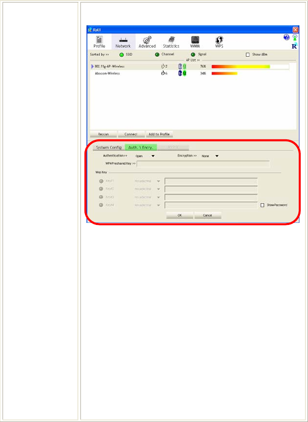
Authentication and Encryption tab:
Authentication Type: There are seven type of
authentication modes including Open, Shared, Leap,
WPA, WPA-PSK, WPA2, WPA2-PSK, and WPA-None.
• Open: If your access point/wireless router is using
"Open” authentication, then the wireless adapter will
need to be set to the same authentication type.
• Shared: Shared Key is when both the sender and the
recipient share a secret key.
• LEAP: Light Extensible Authentication Protocol. It is
an EAP authentication type used primarily in Cisco
Aironet WLANs. It encrypts data transmissions using
dynamically generated WEP keys, and supports mutual
authentication (only with CCX mode enabled.)
• WPA-PSK: WPA-PSK offers two encryption
methods, TKIP and AES. Select the type of algorithm,

- 18 -
TKIP or AES and then enter a WPA Shared Key of
8-63 characters in the WPA Pre-shared Key field.
Encryption Type: For open and shared authentication
mode, the selection of encryption type are None and WEP.
For WPA, WPA2, WPA-PSK and WPA2-PSK
authentication mode, the encryption type supports both
TKIP and AES.
WPA Pre-shared Key: This is the shared secret between
AP and STA. For WPA-PSK and WPA2-PSK
authentication mode, this field must be filled with
character longer than 8 and less than 32 length.
WEP Key: Only valid when using WEP encryption
algorithm. The key must match with the AP’s key. There
are several formats to enter the keys.
• Hexadecimal (40bits): 10 Hex characters.
• Hexadecimal (128bits): 32Hex characters.
• ASCII (40bits): 5 ASCII characters.
• ASCII (128bits): 13 ASCII characters.
Show Password: Check this box to show the password
you entered.
802.1x Setting: When user use radius server to
authenticate client certificate for WPA authentication
mode.
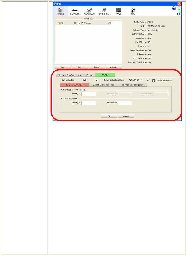
802.1x tab:
- 19 -
EAP Method:
• PEAP: Protect Extensible Authentication Protocol.
PEAP transport securely authentication data by using
tunneling between PEAP clients and an authentication
server. PEAP can authenticate wireless LAN clients
using only server-side certificates, thus simplifying
the implementation and administration of a secure
wireless LAN.
• TLS / Smart Card: Transport Layer Security.
Provides for certificate-based and mutual
authentication of the client and the network. It relies
on client-side and server-side certificates to perform
authentication and can be used to dynamically
generate user-based and session-based WEP keys to
secure subsequent communications between the
WLAN client and the access point.
• TTLS: Tunneled Transport Layer Security. This
security method provides for certificate-based, mutual
authentication of the client and network through an

- 20 -
encrypted channel. Unlike EAP-TLS, EAP-TTLS
requires only server-side certificates.
• EAP-FAST: Flexible Authentication via Secure
Tunneling. It was developed by Cisco. Instead of
using a certificate, mutual authentication is achieved
by means of a PAC (Protected Access Credential)
which can be managed dynamically by the
authentication server. The PAC can be provisioned
(distributed one time) to the client either manually or
automatically. Manual provisioning is delivery to the
client via disk or a secured network distribution
method. Automatic provisioning is an in-band, over
the air, distribution. For tunnel authentication, only
support "Generic Token Card" authentication now.
• MD5-Challenge: Message Digest Challenge.
Challenge is an EAP authentication type that provides
base-level EAP support. It provides for only one-way
authentication - there is no mutual authentication of
wireless client and the network.
Tunnel Authentication:
• Protocol: Tunnel protocol, List information including
EAP-MSCHAP v2, EAP-TLS/Smart card, and
Generic Token Card.
• Tunnel Identity: Identity for tunnel.
• Tunnel Password: Password for tunnel.
Session Resumption: User can click the box to enable or
disable this function.
ID\PASSWORD tab:
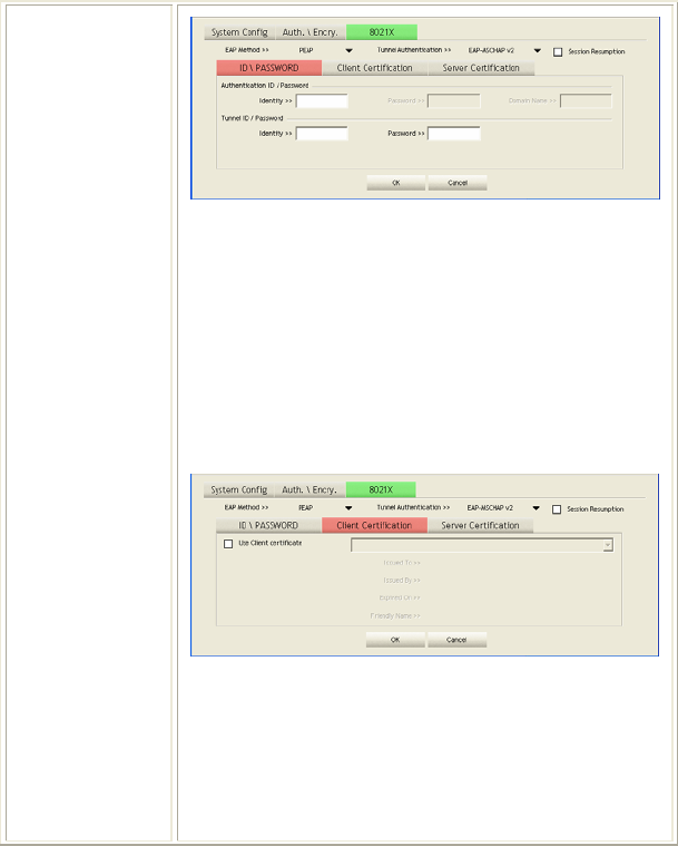
- 21 -
ID/ PASSWORD: Identity and password for server.
• Authentication ID / Password: Identity, password
and domain name for server. Only "EAP-FAST" and
"LEAP" authentication can key in domain name.
Domain name can be keyed in blank space.
• Tunnel ID / Password: Identity and Password for
server.
OK: Click to save settings and exit this page.
Cancel: Click to call off the settings and exit.
Client Certification tab:
Client Certification: Client Certicate for server
authentication.
Use Client certification: Choose to enable server
authentication.
OK: Click to save settings and exit this page.
Cancel: Click call off the settings and exit.
Server Certification tab:
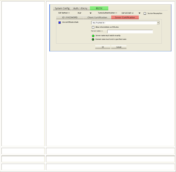
- 22 -
Use Certificate chain: Choose use server that issuer of
certificates.
Allow intimidate certificates: It must be in the server
certificate chain between the server certificate and the
server specified in the certificate issuer must be field.
Server name: Enter an authentication sever root.
Server name must match exactly: Click to enable or
disable this function.
Domain name must end in specified name: Click to
enable or disable this function.
OK: Click to save settings and exit this page.
Cancel: Click call off the settings and exit.
Delete Click to delete an existing profile.
Edit Click to edit a profile.
Activate Click to make a connection between devices.
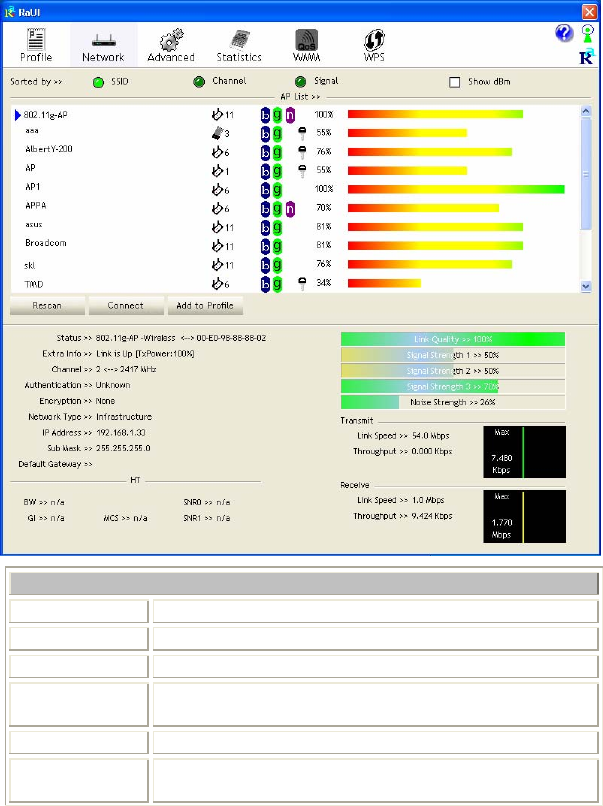
Network
The Network page displays the information of surrounding APs from last scan
result. The tab lists the information including SSID, Network type, Channel,
Wireless mode, Security-Enabled and Signal.
- 23 -
Network Tab
Sorted by Indicate that AP list are sorted by SSID, Channel or Signal.
Show dBm Check the box to show the dBm of the AP list.
SSID Shows the name of BSS network.
Network Type Network type in use, Infrastructure for BSS.
Channel Shows the currently used channel.
Wireless mode AP support wireless mode. It may support 802.11a,
802.11b, 802.11g or 802.11n wireless mode.
- 24 -
Encryption Shows the encryption type currently in use. Valid value
includes WEP, TKIP, AES, and Not Use.
Signal Shows the receiving signal strength of specified network.
Rescan Click to refresh the AP list.
Connect Select an item on the list and then click to make a
connection.
Add to Profile Select an item on the list and then click to add it into the
profile list.
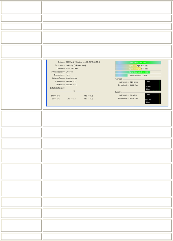
Link status
Status Shows the current connection status. If there is no
connection existing, it will show Disconnected.
Extra Info Shows the link status.
Channel Shows the current channel in use.
Authentication Authentication mode used within the network, including
Unknown, WPA-PSK, WPA2-PSK, WPA and WPA2.
Encryption Shows the encryption type currently in use. Valid value
includes WEP, TKIP, AES, and Not Use.
Network Type Network type in use, Infrastructure for BSS.
IP Address Shows the IP address information.
Sub Mask Shows the Sub Mask information.
Default
Gateway Shows the default gateway information.
Link Quality Shows the connection quality based on signal strength and
- 25 -
TX/RX packet error rate.
Signal
Strength
1, 2 and 3
Shows the Receiving signal strength, you can choose to
display as percentage or dBm format.
Noise Strength Shows the noise signal strength.
Transmit Shows the current Link Speed and Throughput of the
transmit rate.
Receive Shows the current Link Speed and Throughput of receive
rate.
Link Speed Shows the current transmitting rate and receiving rate.
Throughput Shows the transmitting and receiving throughput in the
unit of K bits/sec.
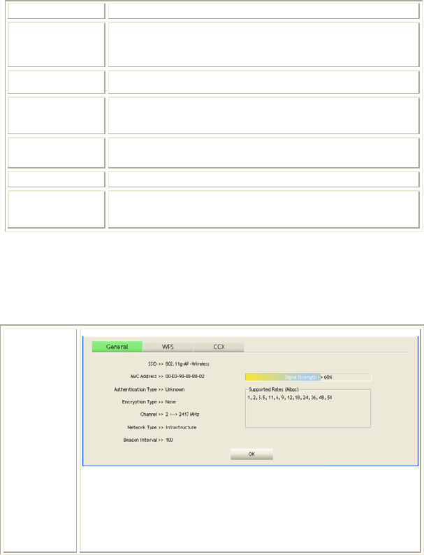
AP information
When you double click on the intended AP, you can see AP's detail information
that divides into three parts. They are General, WPS, CCX information. The
introduction is as following:
General
General information contain AP's SSID, MAC address,
Authentication Type, Encryption Type, Channel, Network Type,
Beacon Interval, Signal Strength and Supported Rates.
OK: Click this button to exit the information screen.
- 26 -
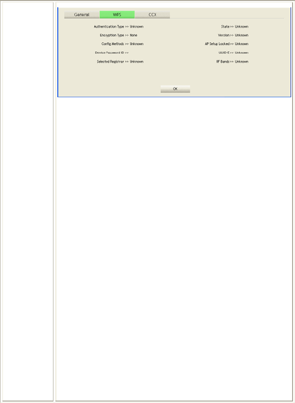
WPS
WPS information contains Authentication Type, Encryption Type,
Config Methods, Device Password ID, Selected Registrar, State,
Version, AP Setup Locked, UUID-E and RF Bands.
Authentication Type: There are four types of authentication
modes supported by RaConfig. They are open, Shared, WPA-PSK
and WPA system.
Encryption Type: For open and shared authentication mode, the
selection of encryption type are None and WEP. For WPA,
WPA2, WPA-PSK and WPA2-PSK authentication mode, the
encryption type supports both TKIP and AES.
Config Methods: Correspond to the methods the AP supports as
an Enrollee for adding external Registrars.
Device Password ID: Indicate the method or identifies the
specific password that the selected Registrar intends to use.
Selected Registrar: Indicate if the user has recently activated a
Registrar to add an Enrollee. The values are "TRUE" and
"FALSE".
State: The current configuration state on AP. The values are
"Unconfigured" and "Configured".
Version: WPS specified version.
AP Setup Locked: Indicate if AP has entered a setup locked state.
UUID-E: The universally unique identifier (UUID) element
generated by the Enrollee. There is a value. It is 16 bytes.
RF Bands: Indicate all RF bands available on the AP. A
dual-band AP must provide it. The values are "2.4GHz" and
"5GHz".
OK: Click this button to exit the information screen.
- 27 -
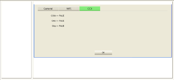
CXX
CCX information contains CCKM, Cmic and Ckip information.
OK: Click this button to exit the information screen.
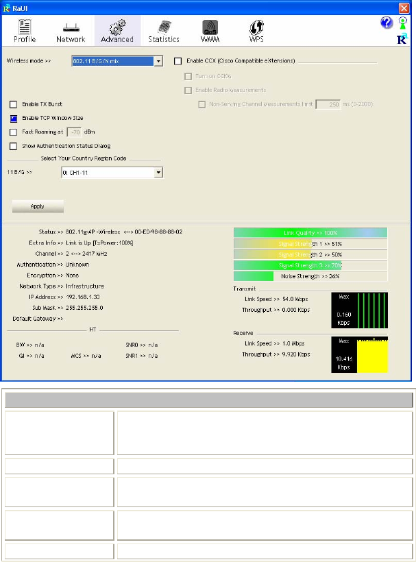
Advanced
This Advanced page provides advanced and detailed settings for your wireless
network.
- 28 -
Advanced Tab
Wireless mode Select wireless mode. There are 802.11b/g/n mixed,
802.11b only and 802.11b/g mixed modes are supported.
Default mode is 802.11b/g/n mixed.
Enable Tx Burst Check to enable the burst mode.
Enable TCP
Window Size Check to increase the transmission quality.
Fast Roaming at Check to set the roaming interval, fast to roaming, setup
by transmits power.
Show When you connect AP with authentication, choose
- 29 -
Authentication
Status Dialog whether show "Authentication Status Dialog" or not.
Authentication Status Dialog displays the process about
802.1x authentications.
Select Your
Country Region
Code
Select your country region code from the pull-down
menu. (for USA frequency band only.)
Enable CCX
(Cisco Compatible
extensions)
Check to enable the CCX function.
• Turn on CCKM
• Enable Radio Measurements: Check to enable the
Radio measurement function.
• Non-Serving Measurements limit: User can set channel
measurement every 0~2000 milliseconds. Default is set
to 250 milliseconds.
Apply Click to apply above settings.
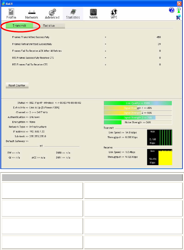
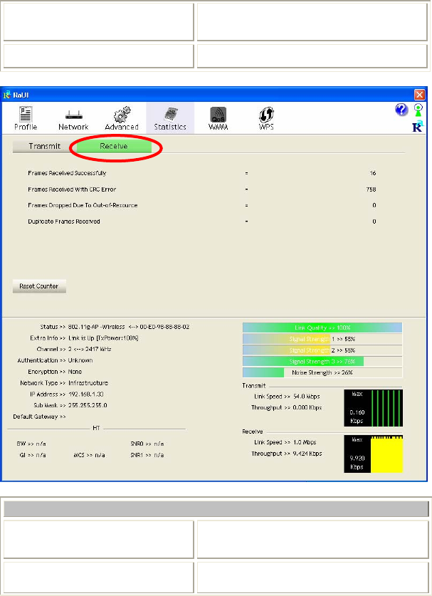
Statistics
The Statistics screen displays the statistics on your current network settings.
- 30 -
Transmit
Frames Transmitted Successfully Shows information of frames successfully
sent.
Frames Retransmitted
Successfully Shows information of frames successfully
sent with one or more reties.
Frames Fail To Receive ACK
After All Retries Shows information of frames failed
transmit after hitting retry limit.
RTS Frames Successfully Receive
CTS Shows information of successfully receive
CTS after sending RTS frame
- 31 -
RTS Frames Fail To Receive
CTS Shows information of failed to receive CTS
after sending RTS.
Reset Counter Click this button to reset counters to zero.
Receive Statistics
Frames Received Successfully Shows information of frames Received
Successfully.
Frames Received With CRC
Error Shows information of frames received with
- 32 -
CRC error.
Frames Dropped Due To
Out-of-Resource Shows information of frames dropped due
to resource issue.
Duplicate Frames Received Shows information of duplicate received
frames.
Reset Counter Click this button to reset counters to zero.
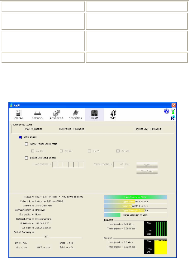
WMM / QoS
The WMM page shows the Wi-Fi Multi-Media power save function and Direct
Link Setup that ensure your wireless network quality.
- 33 -
WMM Enable Check the box to enable Wi-Fi Multi-Media
function.
WMM- Power Save Enable Select which ACs you want to enable.
Direct Link Setup Enable Check the box to enable Direct Link Setup.
MAC Address The setting of DLS indicates as follow :
Fill in the blanks of Direct Link with MAC
Address of STA, and the STA must conform to
two conditions:
• Connecting with the same AP that supports
DLS feature.
• DSL enabled.
Timeout Value Timeout Value represents that it disconnect
automatically after few seconds. The value is
integer that must be between 0~65535. It
represents that it always connects if the value is
zero. Default value of Timeout Value is 60
seconds.
Apply Click this button to apply the settings.
Tear Down Select a direct link STA, then click "Tear Down"
button to disconnect the STA.
WPS
The primary goal of Wi-Fi Protected Setup (Wi-Fi Simple Configuration) is to
simplify the security setup and management of Wi-Fi networks. The STA as an
Enrollee or external Registrar supports the configuration setup using PIN
(Personal Identification Number) configuration method or PBC (Push Button
Configuration) method through an internal or external Registrar.
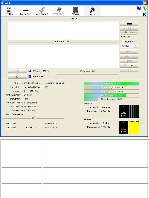
- 34 -
WPS AP List Display the information of surrounding APs with WPS IE
from last scan result. List information included SSID,
BSSID, Channel, ID (Device Password ID),
Security-Enabled.
Rescan Issue a rescan command to wireless NIC to update
information on surrounding wireless network.
Information Display the information about WPS IE on the selected
network. List information included Authentication Type,

- 35 -
Encryption Type, Config Methods, Device Password ID,
Selected Registrar, State, Version, AP Setup Locked,
UUID-E and RF Bands.
PIN Code 8-digit numbers. It is required to enter PIN Code into
Registrar using PIN method.
Config Mode Our station role-playing as an Enrollee or an external
Registrar.
Detail Information about Security and Key in the credential.
Connect Command to connect to the selected network inside
credentials. The active selected credential is as like as the
active selected Profile.
Rotate Command to rotate to connect to the next network inside
credentials.
Disconnect Stop WPS action and disconnect this active link. And
then select the last profile at the Profile Page. If there is
an empty profile page, the driver will select any
non-security AP.
PIN Start to add to Registrar using PIN (Personal
Identification Number) configuration method. If STA
Registrar, remember that enter PIN Code read from your
Enrollee before starting PIN.
PBC Start to add to AP using PBC (Push Button
Configuration) method.
WPS associate IE Send the association request with WPS IE during WPS
setup. It is optional for STA.
WPS probe IE Send the probe request with WPS IE during WPS setup.
- 36 -
It is optional for STA.
Progress Bar Display rate of progress from Start to Connected status.
Status Bar Display currently WPS Status.
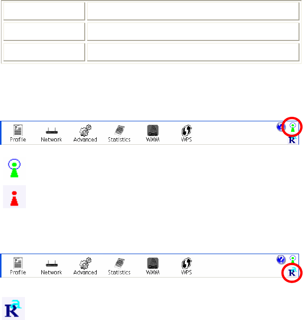
Radio On/Off
Click this icon to turn on radio function.
Click this icon to turn off radio function.
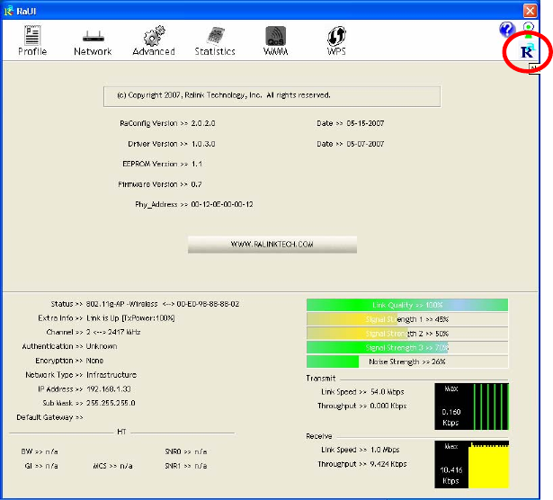
About
Click this button to show the information of the wireless card including,
RaConfig Version/ Date, Driver Version/ Date, EEPROM Version, Firmware
Version and Phy_Address.
- 37 -
- 38 -
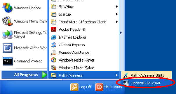
UNINSTALLATION
In case you need to uninstall the utility and driver, please refer to below steps. (As
you uninstall the utility, the driver will be uninstalled as well.)
1. Go to Start Æ Programs ÆRalink Wireless Æ Uninstall.
- 39 -
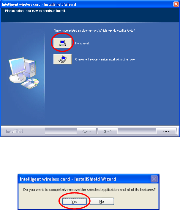
2. Select Remove all button and click Next to start uninstalling.
3. Click Yes to complete remove the selected application and all of its
features.
- 40 -
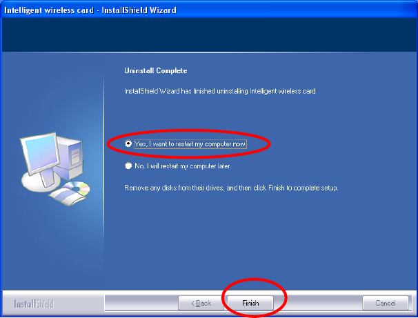
4. Select “Yes, I want to restart my computer now” and then click
Finish to complete the uninstallation.

Manual
For
Motorola Bluetooth
Version 2.1.2

Motorola Bluetooth Manual
V2.1.2 1
Notices
©2008 Motorola, Inc.
1303 East Algonquin Road
Schaumburg, IL 60196
All rights reserved
Printed in U.S.A.
Proprietary Material
Information and software in this document are proprietary to Motorola, Inc. and without the express prior
permission of an officer of Motorola, Inc. may not be copied, reproduced, disclosed to others, published, or
used, in whole or in part, for any purpose other than that for which it is being made available.
This document is for information purposes only and is subject to change without notice.
Information on the World Wide Web
Additional company and product information can be found on our Internet Web site at:
http://www.motorola.com/pcsolutions

Motorola Bluetooth Manual
V2.1.2 2
1 Installation
To install Motorola Bluetooth, you’ll need a PC with Microsoft Windows
XP with Service Pack 2 operating system or later.
If you have installed the previous version of Motorola Bluetooth, de-install
it before installation of the new version.
To start installation, plug in your Bluetooth dongle (it must be based on
CSR Bluetooth chipset) and launch BluetoothSetup.exe from your
installation disk – the Installation Wizard will appear.
Follow the steps specified by the Installation Wizard:
• “Welcome” page
• “License Agreement” page
• “Select Destination Location” page – “C:\Program Files\
Motorola\Bluetooth,” by default
• “Select Start Menu Folder” page – “Bluetooth,” by default
On the “Ready to Install” Installation Wizard page, click the “Install”
button to start the installation process.
When the installation process has completed, click the “Finish” button.
After installation, the Motorola Bluetooth Tray icon should appear in the
System Tray and the “My Bluetooth” desktop icon should appear on your
desktop.
To un-install Motorola Bluetooth, run the un-installation wizard from the
“Start Menu” and follow the wizard instructions. To finish un-installation,
reboot the system – all remaining files will be deleted.
Motorola Bluetooth Manual
V2.1.2 3
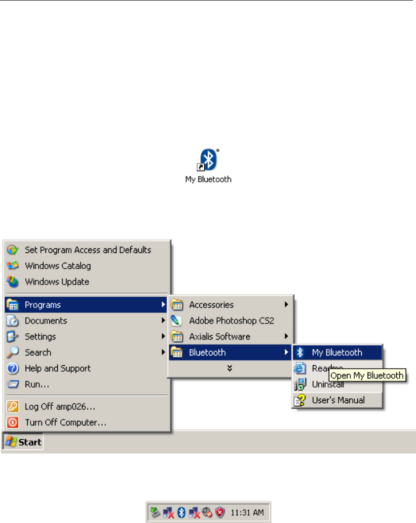
2 Exploring the Bluetooth Environment
“My Bluetooth” explorer window provides you with an easy way to
explore your Bluetooth environment. There are several ways to open “My
Bluetooth” explorer window:
• Double-click on the “My Bluetooth” desktop icon
• Launch “My Bluetooth” from “Start/Programs/Bluetooth/”
• Double-click on the Motorola Bluetooth tray icon
• Select “Open My Bluetooth” from the Motorola Bluetooth tray
application context menu
Motorola Bluetooth Manual
V2.1.2 4
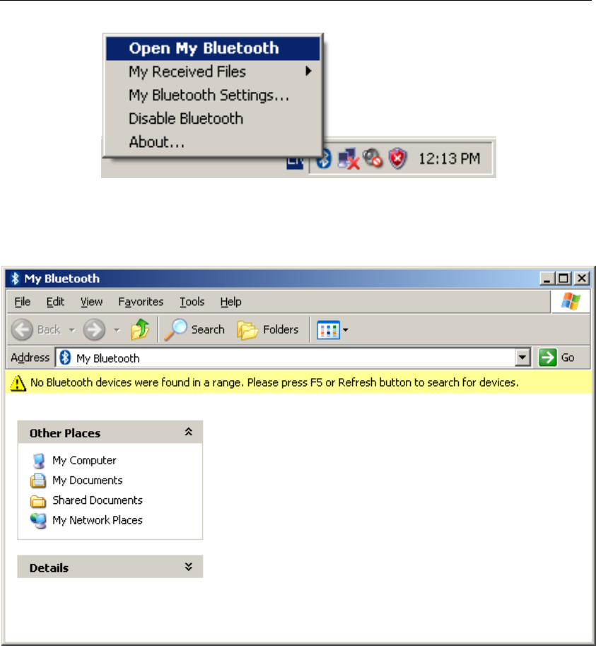
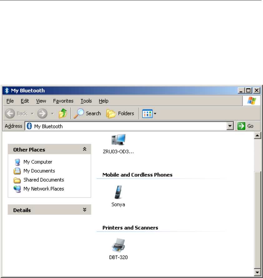
The “My Bluetooth” window, with no devices found, looks like the
screenshot below.
If it’s the first time you’ve opened a “My Bluetooth” window, there will
be no devices found and the “My Bluetooth” window will be empty. Press
the “F5” or Refresh button to start device discovery.
You can verify if the software is discovering devices with the Motorola
Bluetooth tray icon. A blue, blinking icon with white Bluetooth logo
indicates that device discovery is in progress.
As soon as a new device is discovered, the “My Bluetooth” window is
updated to show the device found.
Motorola Bluetooth Manual
V2.1.2 5
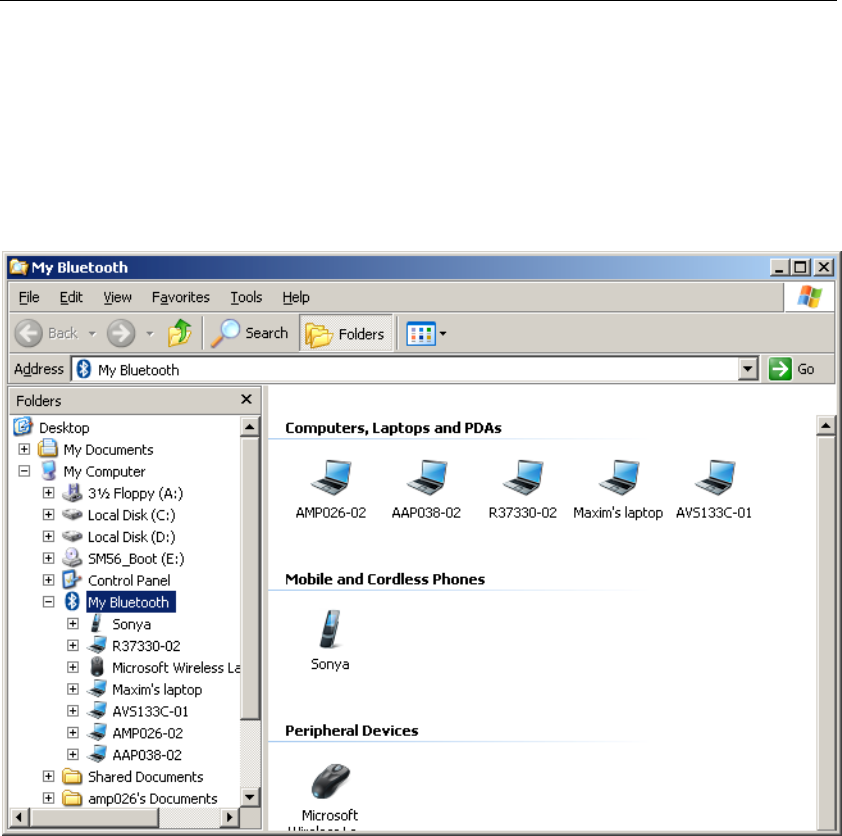
When the tray icon switches from a blue revolving to a blue solid state, it
means that device discovery is finished and you can explore the found
devices.
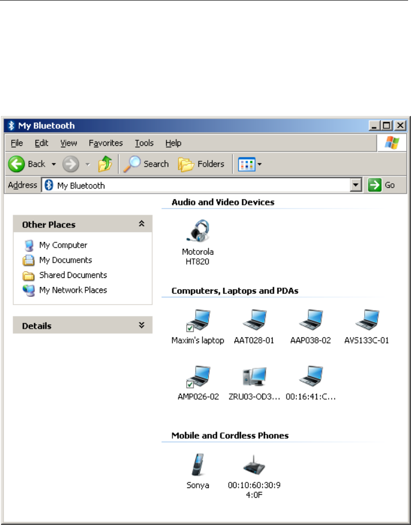
You can view the “My Bluetooth” window in various ways. The example
window below shows device icons in groups arranged by “Device Type.”
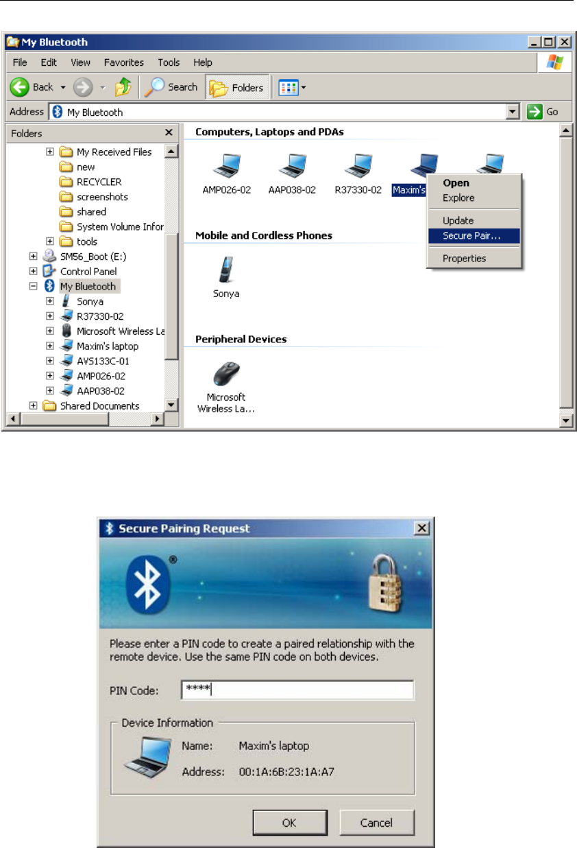
Most Bluetooth devices require authentication (or pairing) to allow
connection. Right-click on the device you would like to pair with and
select “Secure Pair…” in the context menu.
Motorola Bluetooth Manual
V2.1.2 6
The “Secure Pairing Request” window will appear, requesting that you
enter a secret PIN code to pair with the selected device.
Motorola Bluetooth Manual
V2.1.2 7
Enter any numeric code in the “PIN Code” field and click the “OK”
button. This PIN code needs to be repeated on the device you are pairing
with.
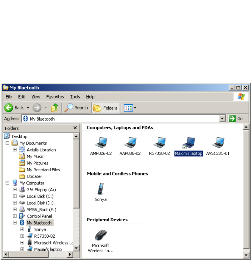
If secret PIN codes entered on the PC and on the device are the same, then
the PC with Motorola Bluetooth becomes paired with another Bluetooth
device, and a green mark is shown on the icon of the paired device.
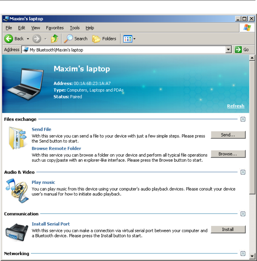
To discover what Bluetooth services are available on the device, double-
click on the device icon and the service discovery procedure will be
started and the “My Bluetooth” view will be changed to the services view.
During service discovery, the Motorola Bluetooth tray icon blinks with a
green Bluetooth logo.
As soon as Bluetooth services discovery is finished, “My Bluetooth” will
be updated to show the services found, which means that PC is connected
to the device and is ready to start using services the device provides.
Motorola Bluetooth Manual
V2.1.2 8
The following sections provide details about particular Bluetooth services
usage.
If you want to un-pair from an already paired device, right-click on the
device icon and select “Unpair” in the context menu.
Motorola Bluetooth Manual
V2.1.2 9
3 Files Transfer over Bluetooth
There are two basic ways to transfer files between your PC and a
Bluetooth device:
• Using the file transfer folder on a remote device
• Using the “send-to” wizard
Using File Transfer Folder
File transfer folder provides you with the most powerful way of file
exchange. Using it, you can:
• Browse the file system on the Bluetooth device
• Transfer files between your PC and the Bluetooth device
• Manipulate objects (files and folders) on the Bluetooth device
(including object removal and the creation of new folders)
And everything noted above can be done with an easy explorer-like
interface.
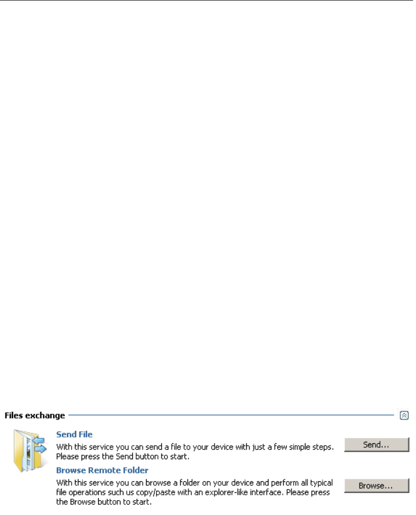
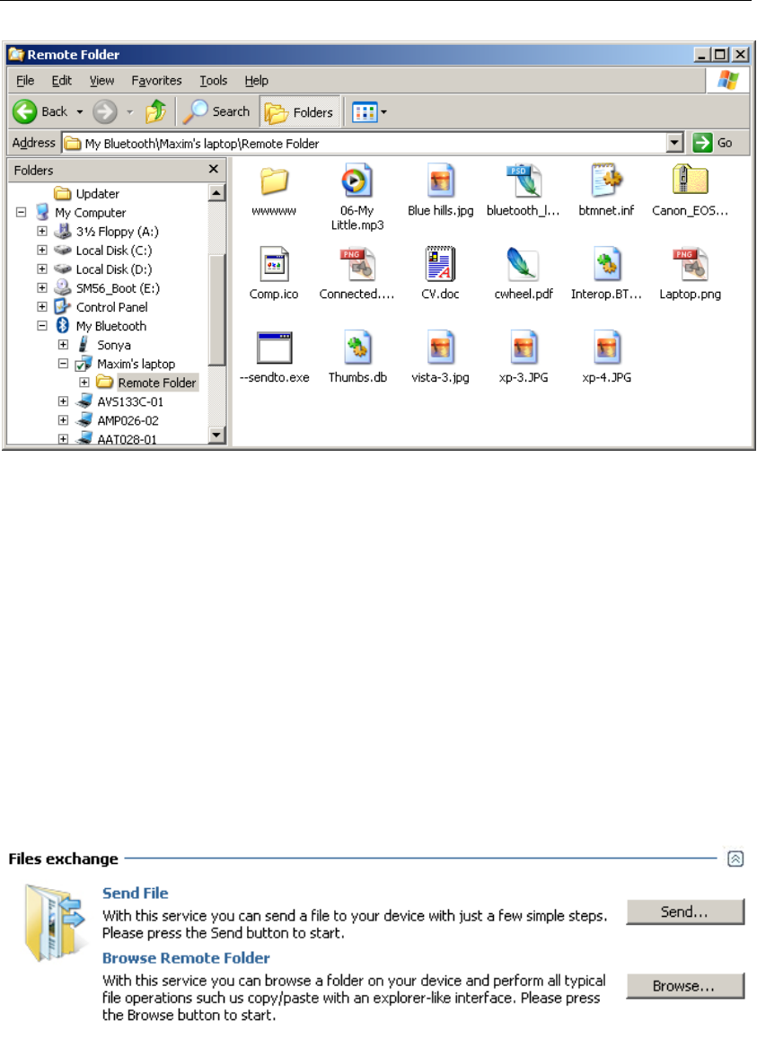
To start browsing the file system on a Bluetooth device, click the
“Browse…” button in the “Files exchange” section of its services view
window.
The file structure of this Bluetooth device will appear as below. (Please
note that the files and folders on your device may be different.)
Motorola Bluetooth Manual
V2.1.2 10
You can easily explore the device file structure in the explorer window
and transfer files between your PC and a device.
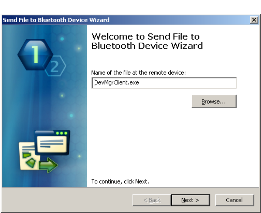
Using the Send-To Wizard
If your Bluetooth device does not have File Transfer Folder, or if you
prefer a wizard-like interface, the “Send File to Bluetooth Device” wizard
can be used to send files to other Bluetooth devices.
To launch the wizard, click the “Send…” button in the “Files exchange”
section of its services view window.
The “Send File to Bluetooth Device” wizard will appear.
Motorola Bluetooth Manual
V2.1.2 11
In the “Send to Bluetooth Device” wizard, click the “Browse…” button to
select file to be sent to a Bluetooth device.
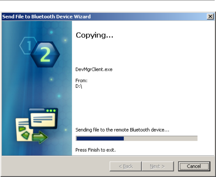
After a file is selected, click “Next” – the transfer process will start with a
progress bar appearing on your monitor, indicating the current transfer
status.
Motorola Bluetooth Manual
V2.1.2 12
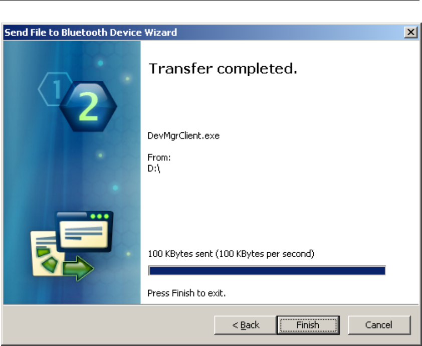
When the transfer process is complete, the wizard page will be updated,
showing transfer statistics.
Motorola Bluetooth Manual
V2.1.2 13
Click “Finish” to close the “Send File to Bluetooth Device” wizard.
When another Bluetooth device initiates file transfer to your PC (for
example, using the “Send via Bluetooth” command), the message window
will appear where a destination path for incoming files can be selected.
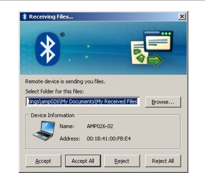
Motorola Bluetooth Manual
V2.1.2 14
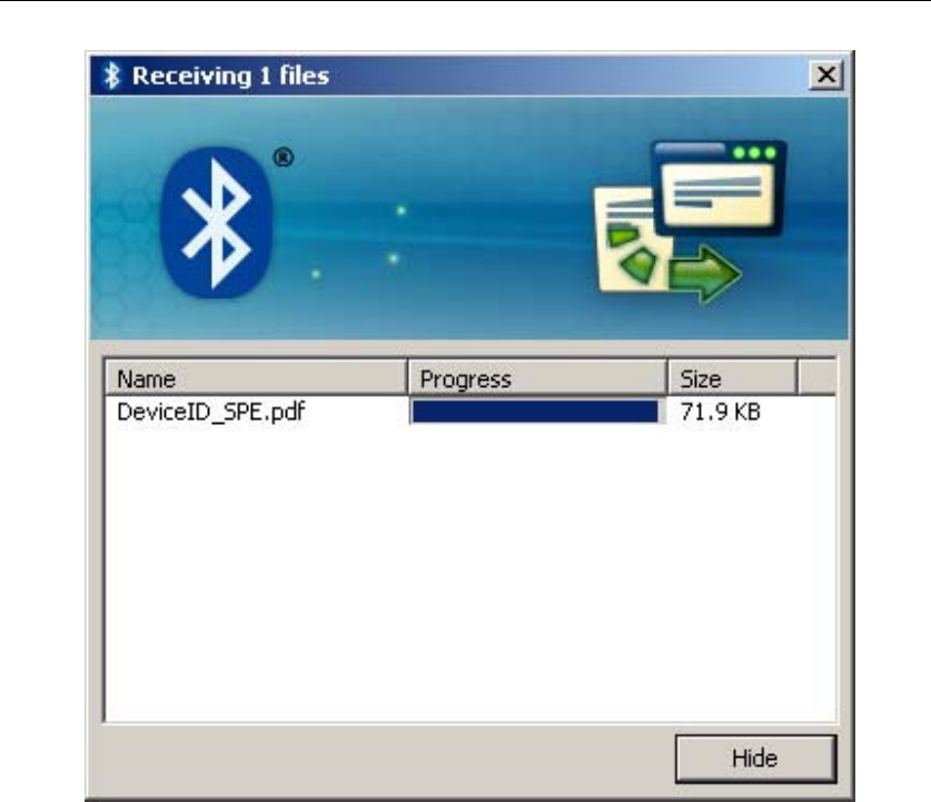
After a path is selected, click “Accept” and the file transfer will start.
Motorola Bluetooth Manual
V2.1.2 15
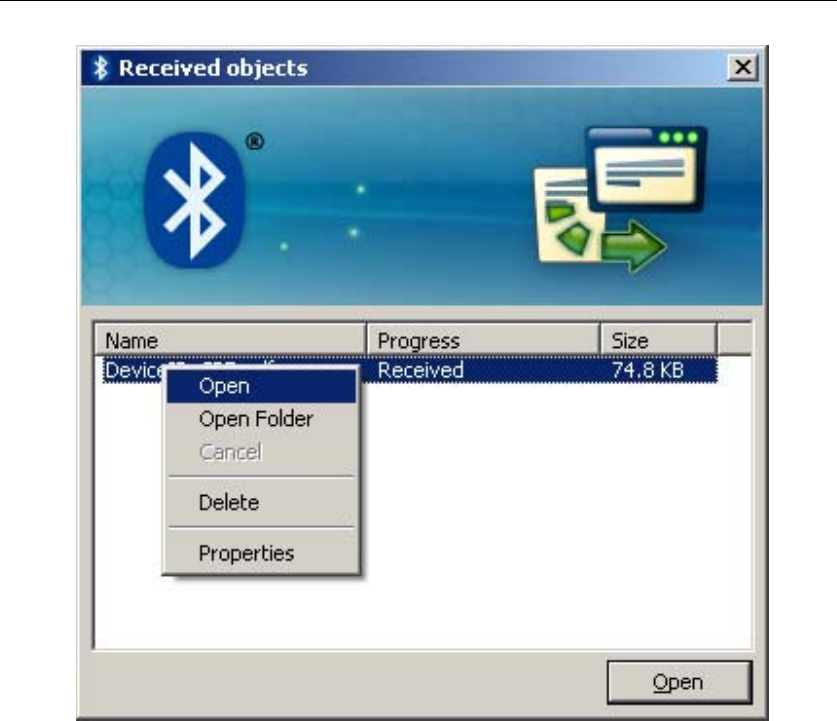
After the file transfer is finished, the window will be updated to remind
you where the received file has been saved.
Motorola Bluetooth Manual
V2.1.2 16
Click the “Hide” button to close this window, or the “Open Folder” button
to open the folder where the received file was saved.
Motorola Bluetooth Manual
V2.1.2 17
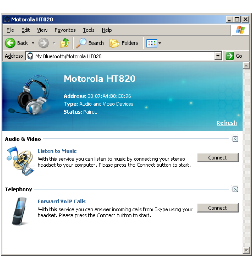
4 Using Bluetooth Headsets
With Motorola Bluetooth, you can use stereo headsets with your PC. Turn
on your headset device and wait while Motorola Bluetooth finds it. The
headset will be displayed in the “Audio and Video Devices” group.
Double-click on the headset device icon in the “My Bluetooth” explorer
window to open a list of available services on this device.
Motorola Bluetooth Manual
V2.1.2 18
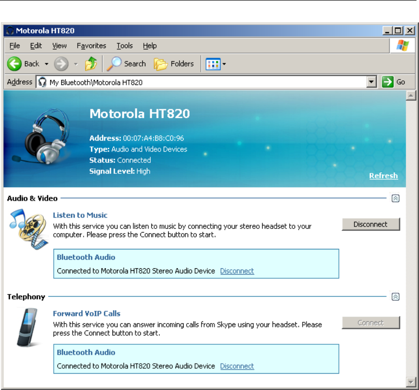
To connect the headset to your PC, click on the “Connect” button in the
“Audio & Video” section of the services view. You may need to perform
additional actions on your device to accept connection. (For example,
some headsets may require pairing to accept connection.)
As soon as connection is established, the service view will be updated to
inform you of the established connection.
Motorola Bluetooth Manual
V2.1.2 19
Now you can use your headset to listen to music from your PC.
Please note: you are allowed to have only one audio connection at a time.
If you want to connect to another audio device, you will need to
disconnect from the existing audio connection first.
To disconnect from an existing audio connection, click on the
“Disconnect” button in the “Audio & Video” section of the services view.
Motorola Bluetooth Manual
V2.1.2 20
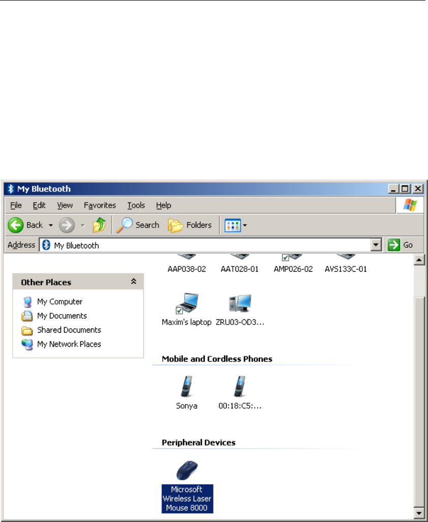
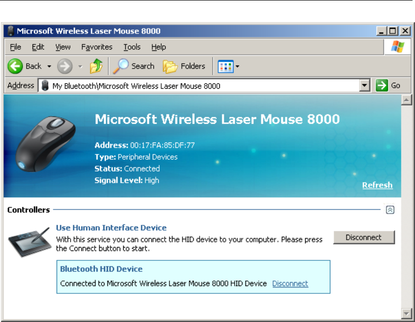
5 Using a Bluetooth Mouse and Keyboard
With Motorola Bluetooth, you can easily connect and use various
Bluetooth devices, such as a mouse, keyboard and other Human Interface
devices (such as gaming pads and the like).
Turn on your Bluetooth Human Interface and wait while Motorola
Bluetooth finds it; the device will be displayed in the “Peripheral Devices”
group.
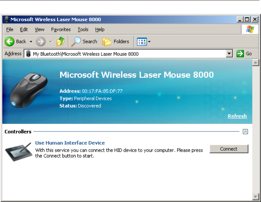
Double-click on the device icon in the “My Bluetooth” explorer window
to open the list of available services on this device.
Motorola Bluetooth Manual
V2.1.2 21
Click on “Connect” to establish connection with your device. You may
need to perform additional actions on your device to accept the connection
(for example, some devices may request you perform pairing before
connection is established).
After connection is established, the service view is updated to inform you
that your device is connected.
Motorola Bluetooth Manual
V2.1.2 22
Now you can use your Bluetooth Human Interface device as an ordinary
device (keyboard, mouse, etc).
To disable a connection with the device, click on the “Disconnect” button.
Motorola Bluetooth Manual
V2.1.2 23
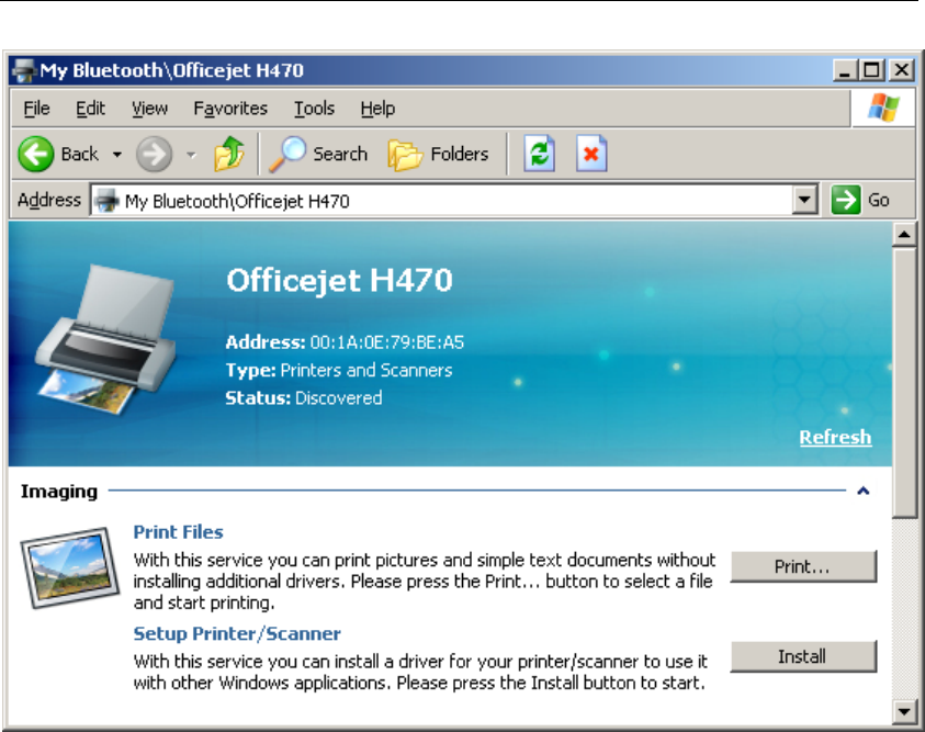
6 Using a Bluetooth Printer
With Motorola Bluetooth, you can easily use your Bluetooth printer.
Turn on your Bluetooth printer and wait while Motorola Bluetooth finds it;
it will be displayed in the “Printers & Scanners” group.
Double-click on the device icon in the “My Bluetooth” explorer window
to open the list of services available on this device.
Motorola Bluetooth Manual
V2.1.2 24
If your printer supports printing without additional drivers, “Print Files”
section will appear in the “Imaging” group in the service you for the
printer. To use this capability, just press the “Print…” button to select a
file and start printing. Please note that only pictures and simple text
documents can be printed with this service.
To use your Bluetooth printer with other Windows applications, you need
to install a driver for it first. Click on the “Install” button to start driver
installation. When you do, the service view is updated to inform you that
driver installation is in progress, and the standard Windows “Add Printer
Device Wizard” is activated.
To proceed with the installation of the driver, you may need an installation
CD with drivers for your particular Bluetooth printer.
As soon as driver installation is finished, the “Install” button will change
to “Uninstall” in the service view. Now you can use your Bluetooth printer
as a regular printer.
To uninstall a driver for your Bluetooth printer, click on the “Uninstall”
button.
Motorola Bluetooth Manual
V2.1.2 25
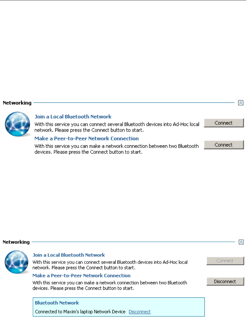
7 Using a Bluetooth Network
Most Bluetooth mobile phones provide Bluetooth networking service.
Using such services, you can establish a regular TCP/IP networking
connection with the device.
If the device provides Bluetooth networking services, a “Networking”
section will be available in the service view for that device.
Click on the “Connect” button to establish a networking connection. You
may need to perform additional actions on your device to accept the
connection.
As soon as connection is established, the service view is updated to inform
you that the device is connected.
Please note: you are allowed to have only one networking connection at a
time. If you need to establish a networking connection with another
device, you need to disable your previous networking connection first.
To disable a networking connection, click on the “Disconnect” button.
Motorola Bluetooth Manual
V2.1.2 26
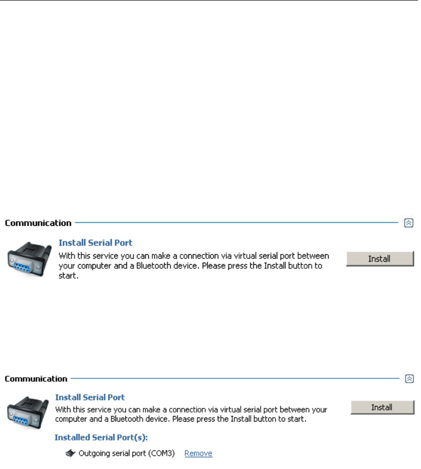
8Using Bluetooth Serial Ports
With virtual serial ports, Bluetooth may be used as a cable replacement for
legacy applications that need a serial connection to operate.
After the virtual serial port is configured, any legacy application may be
run on either device, using the virtual serial port as if there was a real
serial cable connecting the two devices.
If the device supports Bluetooth serial ports, a “Communication” section
will be available in the service view for that device.
Click the “Install” button to configure a serial port for the device. As soon
as the driver is configured, the service view is updated to inform you of
installed serial ports.
Please note: serial ports installed for a particular device can be used only
for communication with that device. You will need to install additional
serial ports if you want to configure serial connections with other
Bluetooth devices.
To remove a Bluetooth serial port, click on the “Remove” link for that
port.
Motorola Bluetooth Manual
V2.1.2 27
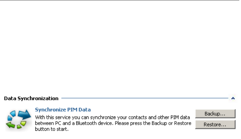
9 Personal Information Management
Some phones and other devices provide access to contacts and other PIM
data over Bluetooth.
If the device supports access to PIM data over Bluetooth, a “Data
Synchronization” section will be available in the service view for that
device.
With Motorola Bluetooth you can read contacts from your device and save
them into a file for backup purpose, and write contacts from a file to the
device (restore them from the backup file).
Motorola Bluetooth Manual
V2.1.2 28
10 Controlling and Configuring Motorola
Bluetooth
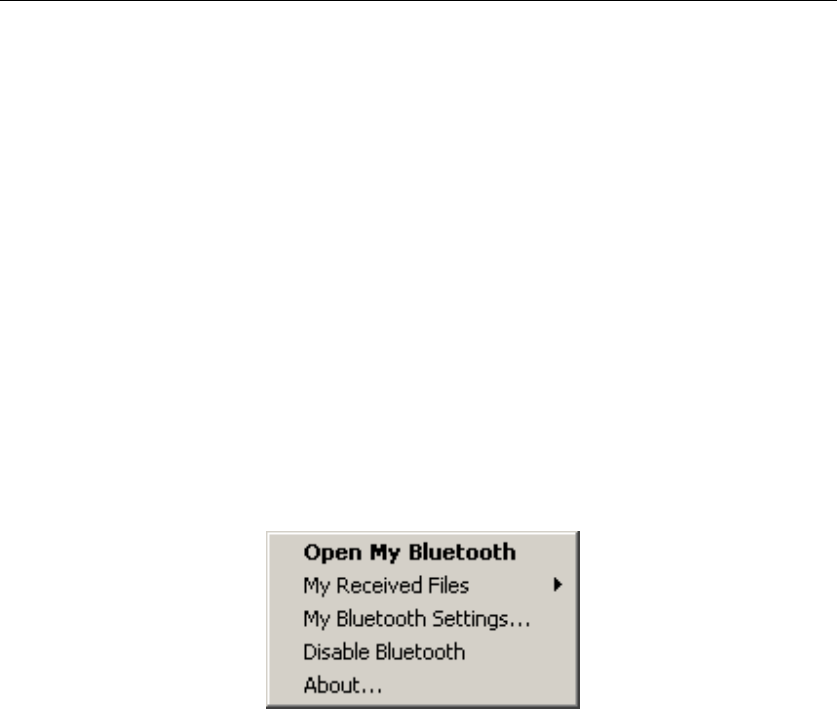
With Motorola Bluetooth tray applications, you can easily control and
configure your Bluetooth device operation.
Motorola Bluetooth tray allows you to:
• Open a Motorola Bluetooth user-interface explorer window
• Open the folder where files received over Bluetooth are saved
• Change Bluetooth settings
• Enable/disable Bluetooth
Right-click on the Motorola Bluetooth Tray icon – the context menu will
appear:
Motorola Bluetooth Tray Icon States
The Motorola Bluetooth tray icon state informs you of the state of your
Bluetooth dongle.
• If you don’t see a Motorola Bluetooth tray icon, your Bluetooth
dongle is not plugged into your PC.
• If the icon appears as a solid red Bluetooth logo, your Bluetooth
dongle is disabled.
• If the icon appears as a solid white Bluetooth logo, your Bluetooth
dongle is plugged into your PC, enabled and is ready for Bluetooth
environment surfing.
• If the icon appears as a blinking white Bluetooth logo, Bluetooth
software is in discovery mode, searching for other Bluetooth devices.
• If the icon appears as a solid green Bluetooth logo, Bluetooth software
is in use and connected to at least one remote Bluetooth device.
• If the icon appears as a blinking green Bluetooth logo, Bluetooth
software is in discovery mode, searching for services available on a
remote Bluetooth device.
Motorola Bluetooth Manual
V2.1.2 29
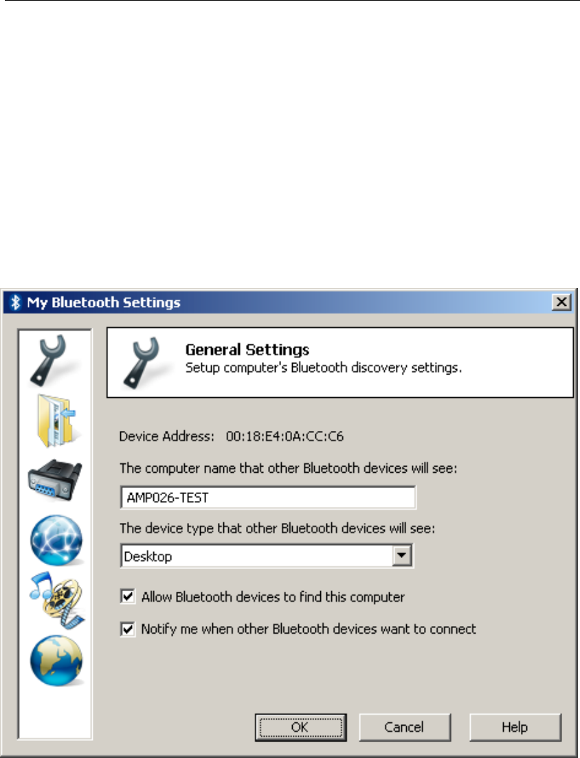
My Bluetooth Settings
The “My Bluetooth Settings” setup window is launched with the “My
Bluetooth Settings…” command in the Motorola Bluetooth tray
application context menu.
General Settings
The first page in the “My Bluetooth Settings” window is a “General
Settings” page.
On this page you can:
• Configure the name and device type of your PC that other
Bluetooth devices will see.
Motorola Bluetooth Manual
V2.1.2 30
• Make your PC undiscoverable by other Bluetooth devices by un-
checking the “Allow Bluetooth devices to find this computer”
option.
• Switch on/off connection notification balloons with the “Notify me
when other Bluetooth devices want to connect’ option.
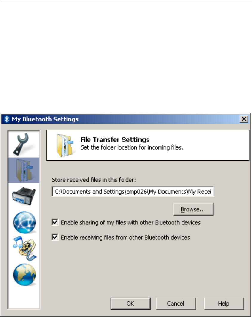
File Transfer Settings
The second page in the “My Bluetooth Settings” window is the “File
Transfer Settings” page.
On this page you can:
• Select the default folder where received-over-Bluetooth files will
be saved.
• Disable/enable accessing Bluetooth File Transfer folder on your
PC with the “Enable sharing of my files with other Bluetooth
devices” option.
Motorola Bluetooth Manual
V2.1.2 31
• Disable/enable receiving objects/files from other Bluetooth devices
with the “Enable receiving files from other Bluetooth devices”
option.
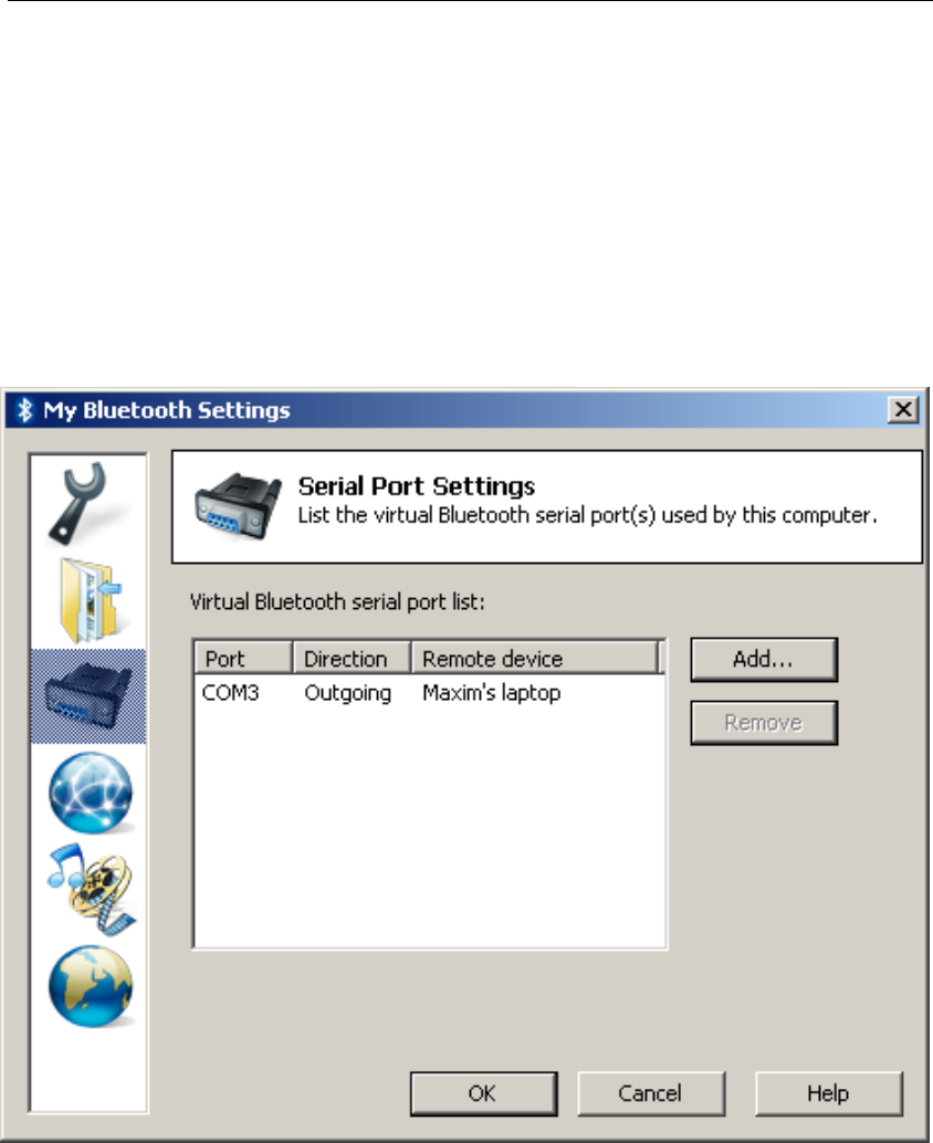
Serial Port Settings
The third page in the “My Bluetooth Settings” window is the “Serial Port
Settings” page.
On this page, you can manage virtual Bluetooth serial ports on your PC.
All configured Bluetooth serial ports are shown on this page.
Also, you can add incoming Bluetooth serial ports on your PC. Incoming
serial ports allow any other Bluetooth device to initiate serial port
connection to your PC (in contrast to outgoing serial ports configured for
particular devices).
Motorola Bluetooth Manual
V2.1.2 32
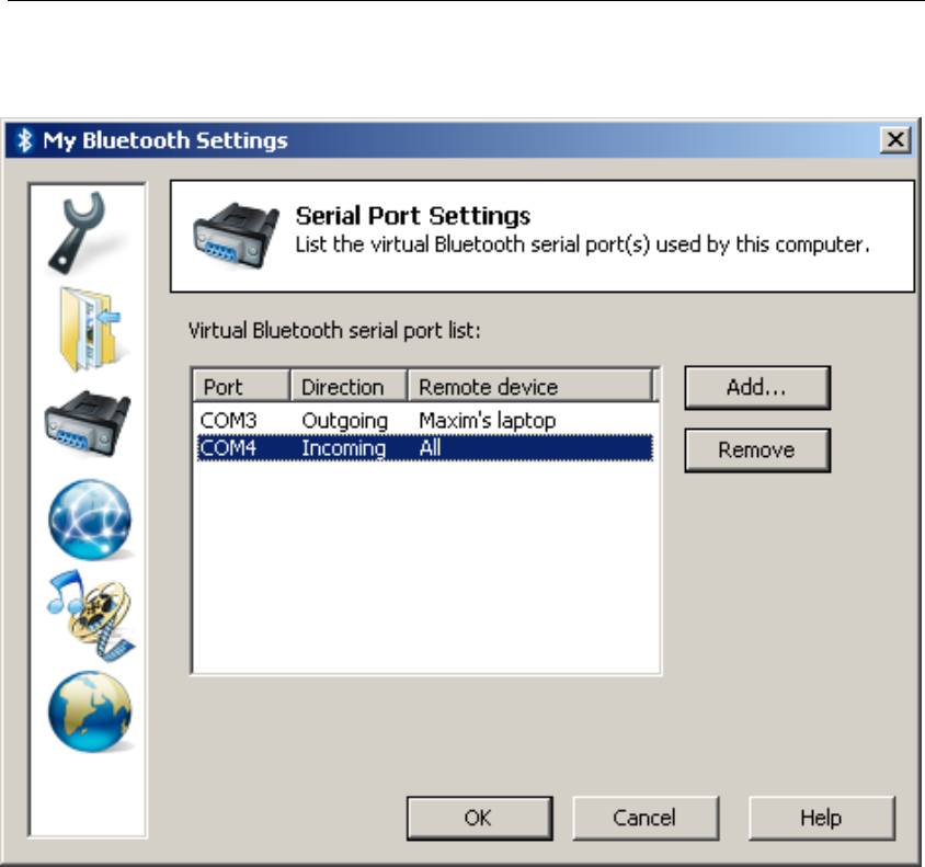
To add an incoming Bluetooth serial port, click on the “Add…” button.
Also, you can remove any Bluetooth serial port (incoming or outgoing) on
this page.
If you need to remove a Bluetooth serial port, select it from the list and
click on the “Remove” button.
Motorola Bluetooth Manual
V2.1.2 33
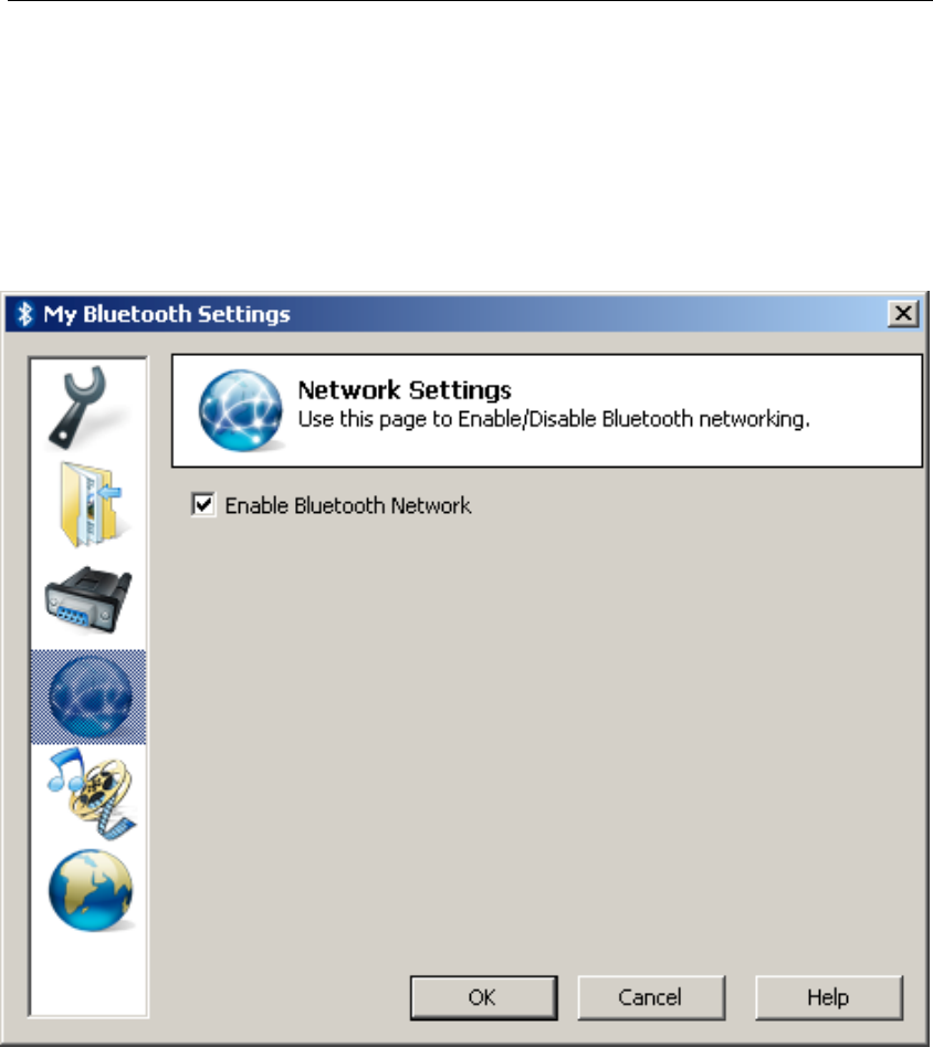
Network Settings
The fourth page in the “My Bluetooth Settings” window is the “Network
Settings” page.
On this page, you can disable/enable Bluetooth Networking capability on
your PC.
By default, Bluetooth Networking is disabled. So, you need to enable it in
order to allow other Bluetooth devices to initiate networking connection to
your PC.
Motorola Bluetooth Manual
V2.1.2 34
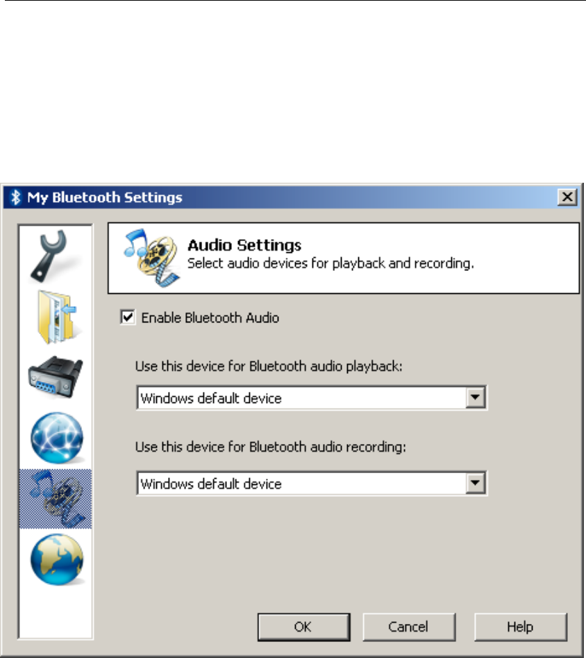
Audio Settings
The fifth page in the “My Bluetooth Settings” window is the “Audio
Settings” page.
On this page, you can enable/disable Bluetooth audio capability on your
PC.
By default, Bluetooth Audio is disabled. So, you need to enable it in order
to allow other Bluetooth devices to initiate audio connection to your PC.
Motorola Bluetooth is able to perfrom audio playback from Bluetooth
devices to audio devices connected to your PC. By default, the music will
be played to Windows default audio device, but you can change it on this
page.
Motorola Bluetooth Manual
V2.1.2 35
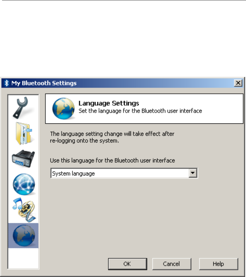
Language Settings
The sixth page in the “My Bluetooth Settings” window is the “Language
Settings” page.
On this page, you can explicitly select the language for the Motorola
Bluetooth user interface.
By default, Motorola Bluetooth tries to select Windows system language
for its interface, and, if it is not supported, the English language is
selected.