Medtronic 8880T2 8880T2 User Manual
Medtronic, Inc. 8880T2
User Manual
Form MEDN-0500 version 3.0
NEUROMODULATION
CONFIDENTIAL DOCUMENT/RECORD
This document/record is electronically controlled, printed copies are considered uncontrolled.
Identifier Version Author
Title:
Pages:
(including this page)
APPROVALS
Signed By Responsibility Date/Time (GMT)
NDHF1205-121337 10.0 Karyn Van Erem
8880CW 8880T2 Technical Manual for Agency Testing
Karyn Van Erem Technical Communications Approver 9/27/2012 3:55:45 PM
63
Medtronic Neuromodulation Clinician
Programmer
8880CW
and Model 8880T2 Telemetry Head
Technical Manual
! USA
Rx only 2013
Filename Date Time
UC200xxxxxx EN
7 x 9 inches (178 mm x 229 mm)
Medtronic
Confidential
HardwareShortManual.xsl - HardwareShortTemplate.fm
Template version: 07-06-2012
M937825A001 Rev X 2013- 03

Filename Date Time
UC200xxxxxx EN
7 x 9 inches (178 mm x 229 mm)
Medtronic
Confidential
HardwareShortManual.xsl - HardwareShortTemplate.fm
Template version: 07-06-2012
M937825A001 Rev X 2013- 03
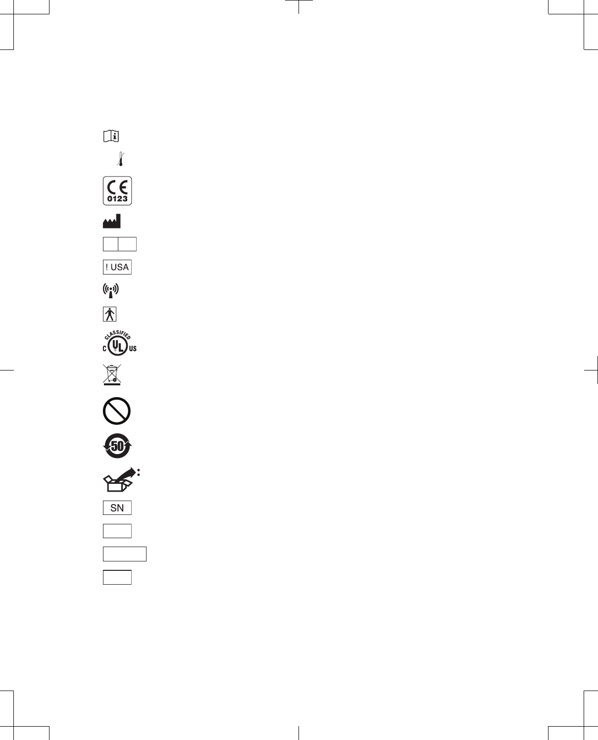
Label symbols
Explanation of symbols on products and packaging. Refer to the appropriate product to see symbols
that apply.
Consult instructions for use
XXX °F
XX °C
-XX °F
-XX °C Temperature limitation
Conformité Européenne (European Conformity). This symbol means that the device fully complies
with AIMD Directive 90/385/EEC (NB 0123) and R&TTE Directive 1999/5/EC.
Manufacturer
EC REP
Authorized representative in the European community
For USA audiences only
Non-ionizing electromagnetic radiation
IEC 60601-1/EN60601-1, Type BF Equipment
Medical – General Medical Equipment as to electrical shock, fire and mechanical hazards only in
accordance with ANSI/AAMI ES 60601-1 and CAN/CSA C22.2 No. 60601-1.
Do not dispose of this product in the unsorted municipal waste stream. Dispose of this product
according to local regulations. See http://recycling.medtronic.com for instructions on proper disposal
of this product.
MR
Magnetic Resonance (MR) Unsafe
Chinese Standard (SJ/T11364-2006) Logo: Electronic Information Products Pollution Control
Symbol. (The date in this logo means the environmental protection use period of the product.)
Package contents:
Serial number
REF Product number or Catalog number
PIN No. PIN number
LOT
Lot number
3
Filename Date Time
UC200xxxxxx EN
7 x 9 inches (178 mm x 229 mm)
Medtronic
Confidential
HardwareShortManual.xsl - HardwareShortTemplate.fm
Template version: 07-06-2012
M937825A001 Rev X 2013- 03

Medtronic® is a trademark of Medtronic, Inc., registered in the U.S. and other countries.
Bluetooth® is a registered trademark of Bluetooth SIG, Inc.
PostScript® (PS) is a trademark of Adobe Systems, Inc., registered in the U.S. and other countries.
PCL® (Printer Command Language) is a registered trademark of Hewlett-Packard Company.
This device complies with Industry Canada license-exempt RSS standard(s). Operation is subject to the
following two conditions: (1) this device may not cause interference, and (2) this device must accept any
interference, including interference that may cause undesired operation of the device.
FCC Information
The following communications regulation information applies to the Model 8880CW Clinician
Programmer and the Model 8880T2 Telemetry Head.
FCC ID: LF58880CW and LF58880T2
These devices comply with part 15 of the FCC Rules. Operation is subject to the following two
conditions: (1) These devices may not cause harmful interference, and (2) these devices must accept
any interference received, including interference that may cause undesired operation.
IMPORTANT: Changes or modifications to these products not authorized by Medtronic, Inc.,
could void the FCC Certification and negate your authority to operate these products.
FCC Class B
NOTE: This equipment has been tested and found to comply with the limits for a Class B digital device,
pursuant to part 15 of the FCC Rules. These limits are designed to provide reasonable protection
against harmful interference in a residential installation. This equipment generates, uses and can
radiate radio frequency energy and, if not installed and used in accordance with the instructions, may
cause harmful interference to radio communications. However, there is no guarantee that interference
will not occur in a particular installation. If this equipment does cause harmful interference to radio or
television reception, which can be determined by turning the equipment off and on, the user is
encouraged to try to correct the interference by one or more of the following measures:
—Reorient or relocate the receiving antenna.
—Increase the separation between the equipment and receiver.
—Connect the equipment into an outlet on a circuit different from that to which the receiver is
connected.
—Consult the dealer or an experienced radio/TV technician for help.
FCC 15.407(e)
According to FCC 15.407(e), the device is intended to operate in the frequency band of 5.15 GHz to
5.25 GHz under all conditions of normal operation. Normal operation of this device is restricted to indoor
use only to reduce any potential for harmful interference to co-channel MSS operations.
FCC RF Radiation Exposure
1. This device must not be co-located or operating in conjunction with any other antenna or transmitter.
2. This device complies with FCC radiation exposure limits set forth for an uncontrolled environment.
FCC 95.1215
This transmitter is authorized by rule under the Medical Device Radiocommunication Service (in part 95
of the FCC Rules) and must not cause harmful interference to stations operating in the 400.150 -
460.000 MHz band in the Meteorological Aids (ie, transmitters and receivers used to communicate
weather data), the Meteorological Satellite, or the Earth Exploration Satellite Services and must accept
4
Filename Date Time
UC200xxxxxx EN
7 x 9 inches (178 mm x 229 mm)
Medtronic
Confidential
HardwareShortManual.xsl - HardwareShortTemplate.fm
Template version: 07-06-2012
M937825A001 Rev X 2013- 03

interference that may be caused by such stations, including interference that may cause undesired
operation. This transmitter shall be used only in accordance with the FCC Rules governing the Medical
Device Radiocommunication Service. Analog and digital voice communications are prohibited. Although
this transmitter has been approved by the Federal Communications Commission, there is no guarantee
that it will not receive interference or that any particular transmission from this transmitter will be free
from interference.
FCC 95.1217
This device may not interfere with stations operating in the 400.150 - 406.000 MHz band in the
Meteorological Aids, Meteorological Satellite, and Earth Exploration Satellite Services and must accept
any interference received, including interference that may cause undesired operations.
5
Filename Date Time
UC200xxxxxx EN
7 x 9 inches (178 mm x 229 mm)
Medtronic
Confidential
HardwareShortManual.xsl - HardwareShortTemplate.fm
Template version: 07-06-2012
M937825A001 Rev X 2013- 03

6
Filename Date Time
UC200xxxxxx EN
7 x 9 inches (178 mm x 229 mm)
Medtronic
Confidential
HardwareShortManual.xsl - HardwareShortTemplate.fm
Template version: 07-06-2012
M937825A001 Rev X 2013- 03

Table of contents
Device description 9
Package contents 9
Device specifications 9
Electrical and operating characteristics 9
Storage and operating characteristics 11
Declaration of Conformity 12
Instructions for use 12
Component identification 12
Programmer component identification 12
Telemetry head component identification 14
Docking station component identification 16
Setting up the programmer and docking station 17
Inserting the rechargeable battery 18
Connecting the power supply and cord 19
Connecting to the USB port 20
Using the docking station 20
Using the telemetry head 23
Connecting to and disconnecting from the programmer 23
Turning the telemetry head on or off 25
Telemetry head LED indicators 25
Initiating telemetry 26
Positioning the telemetry head in a sterile field 27
Programmer function overview 28
Turning the programmer on 28
Data entry using the programmer touchscreen 29
Configure initial user settings 33
Overview of programmer desktop 35
Turning the programmer off 36
Putting the programmer into Standby 36
Programmer Control Panel 37
Messages 38
Control Menu 38
Utilities 40
Managing the programmer system 40
Patient Data Center 45
Patient Record Security 46
Patient List 46
Session List 47
Reports 49
Moving patient records from one programmer to another 50
8880CW 2013-03 English 7
Filename Date Time
UC200xxxxxx EN
7 x 9 inches (178 mm x 229 mm)
Medtronic
Confidential
HardwareShortManual.xsl - HardwareShortTemplate.fm
Template version: 07-06-2012
M937825A001 Rev X 2013- 03

Removing patient records from the programmer without exporting 51
Maintenance 51
Installing or removing the programmer battery 52
Charging the programmer battery 54
Changing the batteries in the telemetry head 55
Calibrating the touchscreen 57
Cleaning 57
Troubleshooting 57
Clinician programmer error messages 57
Network connection troubleshooting 58
Printer connection troubleshooting 59
Resetting the Patient data security password 59
Safety and technical checks 60
8 English 8880CW 2013-03
Filename Date Time
UC200xxxxxx EN
7 x 9 inches (178 mm x 229 mm)
Medtronic
Confidential
HardwareShortManual.xsl - HardwareShortTemplate.fm
Template version: 07-06-2012
M937825A001 Rev X 2013- 03

Device description
The Medtronic Neuromodulation Model 8880CW Clinician Programmer is a portable device used to
program Medtronic Neuromodulation devices. The programmer is equipped with a color touchscreen,
Bluetooth® wireless technology, wireless local area network (WLAN) connection, universal serial bus
(USB) port, rechargeable battery, and docking capability. Network connectivity is provided so that
reports can be printed, saved, or sent via email. Refer to the System Components sheet provided with
the programmer for a list of the available system components.
The Medtronic Neuromodulation Model 8880CW Clinician Programmer is intended for use with
Medtronic Neuromodulation therapies and devices. The Model 8880T2 Telemetry Head is intended for
use in conjunction with the Model 8880CW Clinician Programmer for communication with Medtronic
Neuromodulation implantable therapy devices. Refer to specific therapy and device guides for complete
information.
Package contents
The programmer package contains:
▪One programmer with software
▪Three stylus pens
▪One rechargeable battery
▪One power supply and cord
▪Product literature
Note: Some system components, including the telemetry head, are packaged separately from the
programmer.
Device specifications
Electrical and operating characteristics
Table 1. Electrical and operating characteristics for the programmer and system components
Description Specification
Model 8880CW Clinician Programmer
Power source Internally powered by a rechargeable lithium ion battery
and also powered by mains electricity through a power
supply
Operating type Continuous
Length 255 mm (10 in)
8880CW 2013-03 English 9
Filename Date Time
UC200xxxxxx EN
7 x 9 inches (178 mm x 229 mm)
Medtronic
Confidential
HardwareShortManual.xsl - HardwareShortTemplate.fm
Template version: 07-06-2012
M937825A001 Rev X 2013- 03

Table 1. Electrical and operating characteristics for the programmer and system components (continued)
Description Specification
Width 43 mm (1.7 in)
Height 255 mm (10 in)
Weight (maximum) 1.5 kg (3.3 lbs)
Screen XGA TFT LCD
LED backlit
1024 x 768 pixels
32 bit color
Size: 264 mm (10.4 in)
Database encryption method AES128
Wireless communication types Bluetooth module integrated circuit # SMWBTM-203B
WLAN module supports 802.11 a/b/g/n
Connections USB port
Docking connection
Model 8880T2 Telemetry Head
Power source Internally powered by 2 AAA alkaline batteries
(nonrechargeable, LR03)
Operating type Continuous
Length 61 mm (2.4 in)
Width 25 mm (1 in)
Height 155 mm (6.1 in)
Weight 255.14 g (0.56 lb)
Communication types/connections Bluetooth module integrated circuit # STA2500D
Proprietary connector
Model 885010 USB System Connector Cable
Length 1.83 m (6 ft)
Rechargeable battery
Type Lithium-ion
3760 mAH 11.1 Vdc
Chemical class 9
UN classification number UN3480
Watt-hour rating 42
Charging time 2.5 hours
Run time (maximum) 3.5 to 4.5 hours (Depends on user settings and number of
cycles.)
Length 112 mm (4.4 in)
Width 14 mm (0.55 in)
Height 113 mm (4.4 in)
Weight 300 g (0.66 lb)
Power supply
Input 100-240 VAC, 47-63 Hz, 1.62-0.72 A
10 English 8880CW 2013-03
Filename Date Time
UC200xxxxxx EN
7 x 9 inches (178 mm x 229 mm)
Medtronic
Confidential
HardwareShortManual.xsl - HardwareShortTemplate.fm
Template version: 07-06-2012
M937825A001 Rev X 2013- 03

Table 1. Electrical and operating characteristics for the programmer and system components (continued)
Description Specification
Output 15 V DC, 4.2 A maximum
Length 3 m (approximately 10 ft)
Docking station
Power source Mains electricity through a power supply
Operating type Continuous
Length 264 mm (10.4 in)
Width 49 mm (1.9 in)
Height (with leg pushed in) 282 mm (11.1 in)
Height (cradle only) 241 mm (9.5 in)
Weight 460 g (1 lb)
Connections Ethernet port (if present) supports 10 megabit per second
(Mbps) and 100 Mbps operations
VGA output connector (optional)
USB port
Video Electronics Standards Association (VESA)/wall or
arm mount of cradle
75 mm (2.95 in) x 75 mm (2.95 in)
Battery charger
Power source Mains electricity through a power supply
Operating type Continuous
Input voltage 15 V
Charging method Constant current and voltage
Charging current 2.3 A
Length 157 mm (6.2 in)
Width 55 mm (2.1 in)
Height 35 mm (1.4 in)
Weight 285 g (0.63 lb)
Storage and operating characteristics
Table 2. Storage and operating characteristics for the programmer and telemetry head
Storage temperature Operating temperature
Programmer –20 ºC (–4 °F) to 60 ºC (140 °F) 0 ºC (32 °F) to 40 ºC (104 °F)
Telemetry head –40 °C (–40 °F) to 70 °C (158 °F) 10 ºC (50 °F) to 40 ºC (104 °F)
8880CW 2013-03 English 11
Filename Date Time
UC200xxxxxx EN
7 x 9 inches (178 mm x 229 mm)
Medtronic
Confidential
HardwareShortManual.xsl - HardwareShortTemplate.fm
Template version: 07-06-2012
M937825A001 Rev X 2013- 03

Declaration of Conformity
Medtronic declares that the Medtronic Neuromodulation Model 8880CW Clinician Programmer,
software, and Model 8880T2 Telemetry Head are in conformity with the essential requirements of
Directive 1999/5/EC on Radio and Telecommunications Terminal Equipment and Directive 90/385/EEC
on Active Implantable Medical Devices.
For additional information, contact the appropriate Medtronic representative listed on the inside back
cover of this manual.
Instructions for use
Component identification
Programmer component identification
The front of the programmer is equipped with a color touchscreen display and light-emitting diode (LED)
indicators (Figure 1 on page 13). See Table 3 on page 12 for a description of the programmer LED
indicators.
The Power button is on the left side of the programmer.
The bottom of the programmer is equipped with a power jack, USB port, and docking connector
(Figure 2 on page 14).
Note: The USB port on the programmer should only be used to connect a USB flash drive, the USB
system connector cable, or a USB printer cable.
The back of the programmer is equipped with a slot for the stylus, camera with light, slot for the
rechargeable battery, Battery Release button, and speaker (Figure 3 on page 14). Serial number
information is also displayed on the back of the programmer.
Table 3. Programmer LED indicators
LED indicator Behavior Description
Bluetooth capability
Solid blue The capability of the programmer to use Bluetooth wireless technology is
enabled. For more information see "Managing the programmer system"
on page 40.
Off The capability of the programmer to use Bluetooth wireless technology is
disabled. For more information see "Managing the programmer system"
on page 40.
Radio-frequency identification (RFID)
Feature is reserved for future use.
12 English 8880CW 2013-03
Filename Date Time
UC200xxxxxx EN
7 x 9 inches (178 mm x 229 mm)
Medtronic
Confidential
HardwareShortManual.xsl - HardwareShortTemplate.fm
Template version: 07-06-2012
M937825A001 Rev X 2013- 03
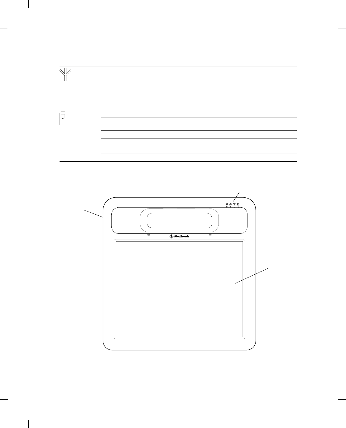
Table 3. Programmer LED indicators (continued)
LED indicator Behavior Description
Wireless local area network (WLAN) capability
Solid blue The capability of the programmer to connect to a wireless network is
enabled. For more information see "Managing the programmer system"
on page 40.
Off The capability of the programmer to connect to a wireless network is
disabled. For more information see "Managing the programmer system"
on page 40.
Power/Battery status
Solid green Mains electricity through the power supply is being used, the battery has
sufficient charge, or the battery has been fully charged.
Solid red The battery is low.
Solid orange The battery is charging.
Flashing orange The programmer is in standby mode.
Off The programmer is off.
Power button
Touchscreen
LED indicators
Figure 1. Programmer (front).
8880CW 2013-03 English 13
Filename Date Time
UC200xxxxxx EN
7 x 9 inches (178 mm x 229 mm)
Medtronic
Confidential
HardwareShortManual.xsl - HardwareShortTemplate.fm
Template version: 07-06-2012
M937825A001 Rev X 2013- 03
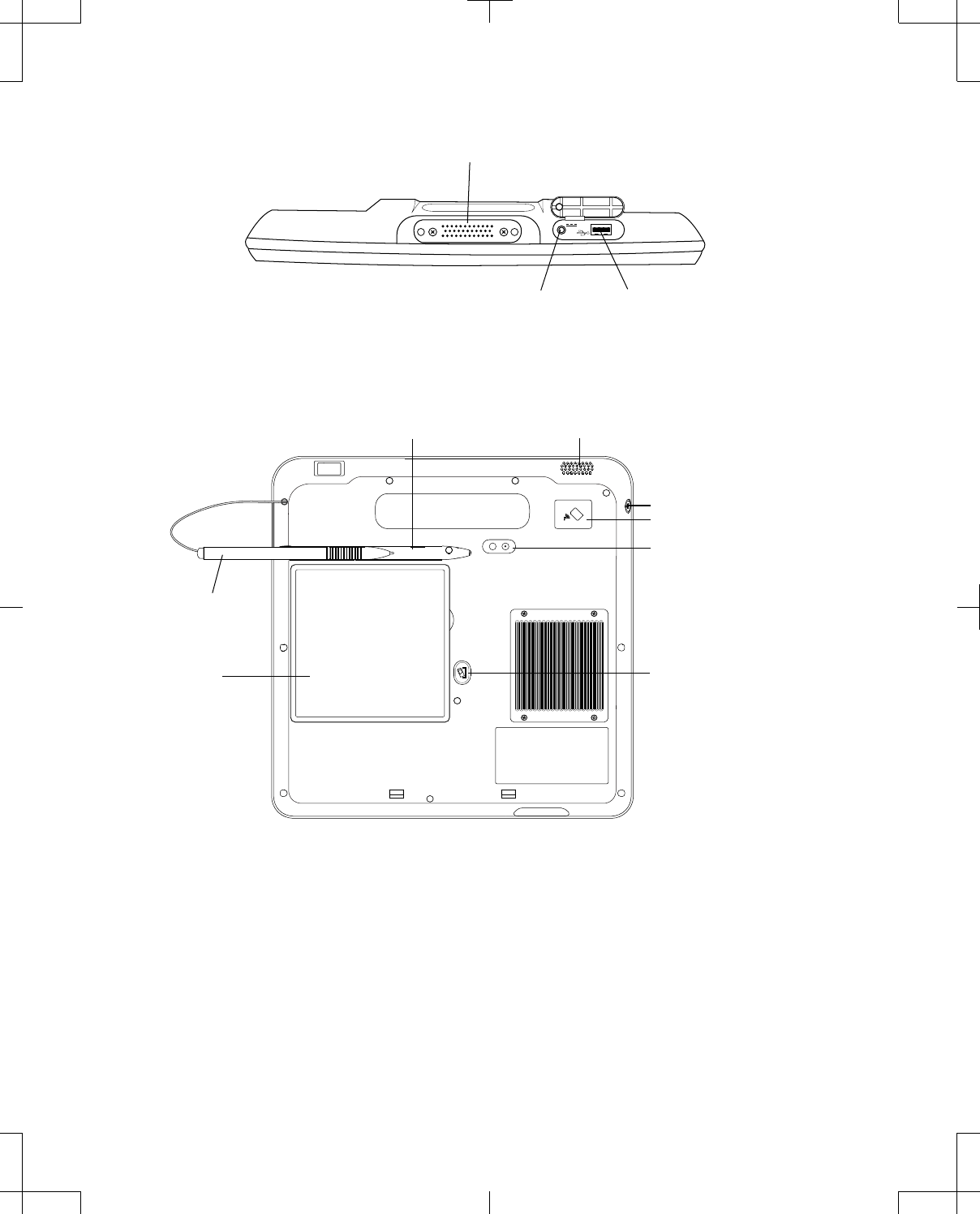
Docking connector
Power jack USB port
Figure 2. Programmer (bottom).
Stylus slot
Stylus
(Connected)
Battery
Power button
Camera with light
RFID
(Reserved for future use)
Battery release
button
Speaker
Figure 3. Programmer (back).
Telemetry head component identification
The telemetry head is handheld and battery-operated. Communication between the telemetry head and
the programmer can occur wirelessly using Bluetooth technology or wired using the Model 885010 USB
System Connector Cable.
The front of the telemetry head is equipped with power and communication status LED indicators, a
Communicate button, battery compartment, and accessory connector. See Table 5 on page 25 for a
14 English 8880CW 2013-03
Filename Date Time
UC200xxxxxx EN
7 x 9 inches (178 mm x 229 mm)
Medtronic
Confidential
HardwareShortManual.xsl - HardwareShortTemplate.fm
Template version: 07-06-2012
M937825A001 Rev X 2013- 03
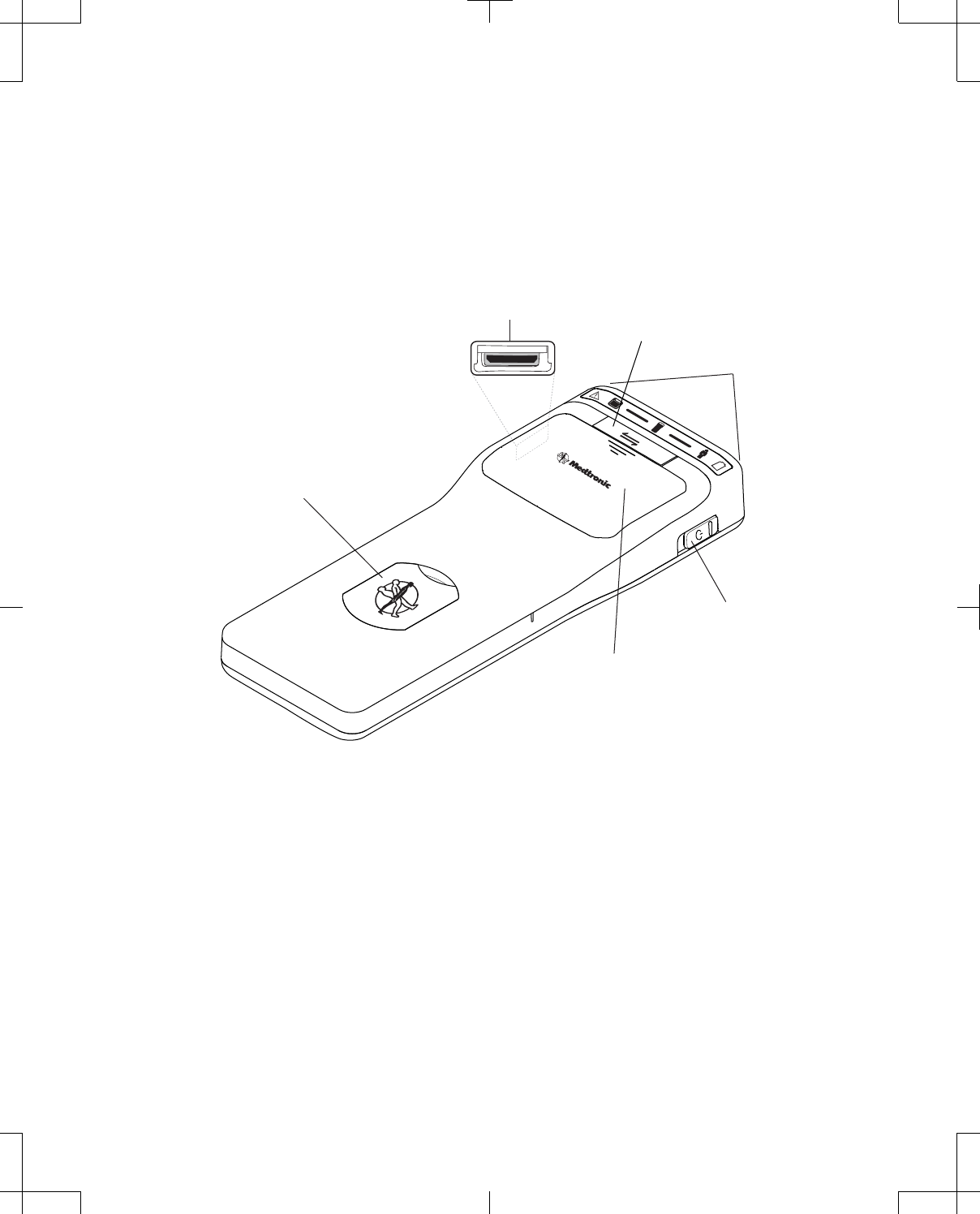
description of the telemetry head LED indicators. The right side of the telemetry head is equipped with a
Power button. The left side of the telemetry head is equipped with a proprietary connector for the USB
System Connector Cable. See Figure 4.
The back side of the telemetry head displays the device label, which shows where the internal antenna
is located (Figure 5 on page 16). The back of the telemetry head is also equipped with an accessory
connector, which can be used to attach the telemetry head to the docking station for storage. See
"Using the docking station" on page 20 for more information.
Battery compartment
Power button
LED indicators
Proprietary connector
Communicate button
Accessory connector
Figure 4. Telemetry head (front and right sides).
8880CW 2013-03 English 15
Filename Date Time
UC200xxxxxx EN
7 x 9 inches (178 mm x 229 mm)
Medtronic
Confidential
HardwareShortManual.xsl - HardwareShortTemplate.fm
Template version: 07-06-2012
M937825A001 Rev X 2013- 03
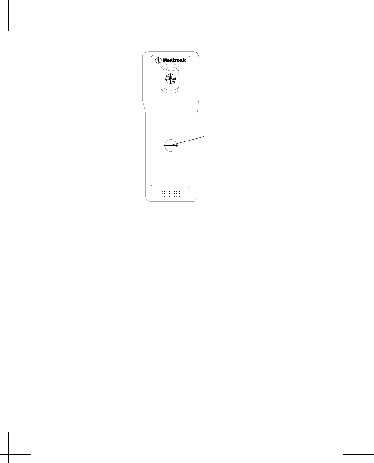
Accessory connector
Internal antenna
Figure 5. Telemetry head (back).
Docking station component identification
The docking station allows the programmer to be docked for charging while providing additional
connections.
The front of the docking station is equipped with a power status LED indicator and cradle for the
programmer that contains docking pins (Figure 6). A solid green LED indicates power is present.
The back of the docking station may be equipped with an Ethernet port with LED indicators, USB port,
video graphics array (VGA) output connector, and power jack (Figure 7 on page 17).
Note: The USB port on the docking station should only be used to connect a USB flash drive, the USB
system connector cable, or a USB printer cable.
The back leg of the docking station is equipped with an accessory connector, which can be used to
attach the telemetry head for storage. See "Using the docking station" on page 20 for more
information.
16 English 8880CW 2013-03
Filename Date Time
UC200xxxxxx EN
7 x 9 inches (178 mm x 229 mm)
Medtronic
Confidential
HardwareShortManual.xsl - HardwareShortTemplate.fm
Template version: 07-06-2012
M937825A001 Rev X 2013- 03
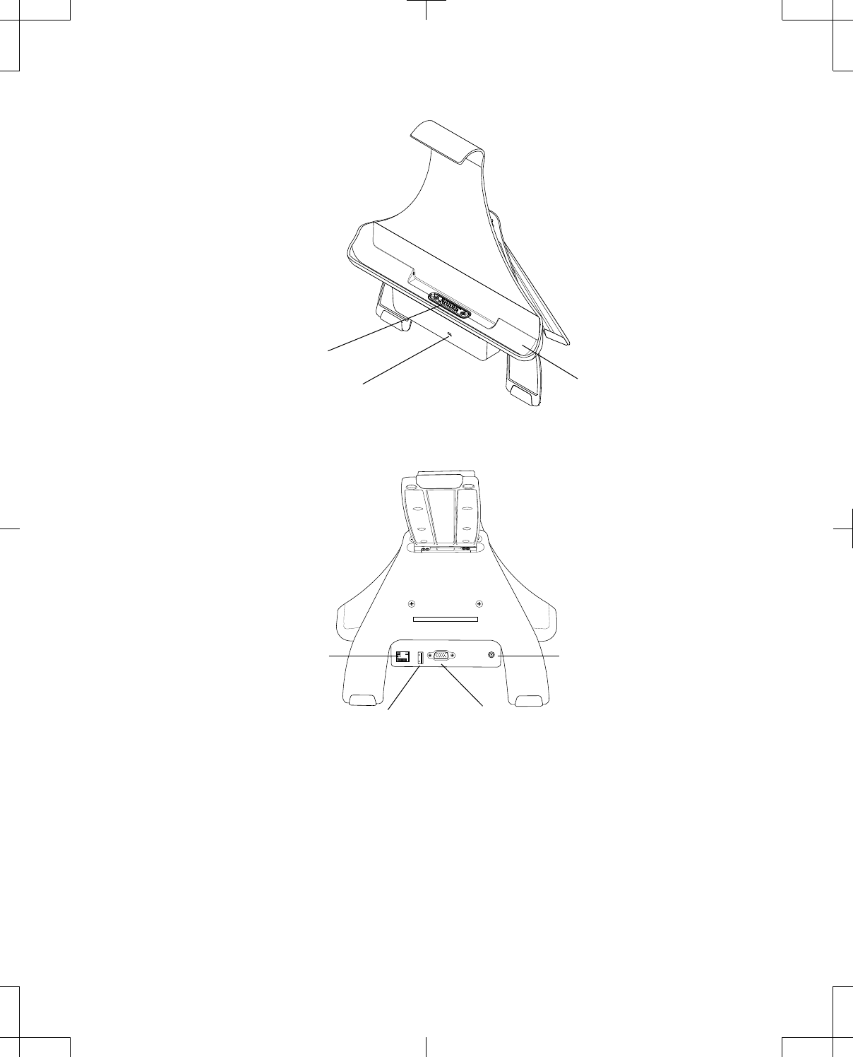
Power indicator
Docking pins
Cradle
Figure 6. Docking station (front).
USB port VGA output connection (optional)
Ethernet port (optional) Power jack
Figure 7. Docking station (back).
Setting up the programmer and docking station
#Caution: If the programmer system components were transported or stored above or below the
specified operating temperature range, allow the items to stabilize at room temperature until they
return to operating temperature. Using the programmer system components within operating
temperature range ensures device functionality.
8880CW 2013-03 English 17
Filename Date Time
UC200xxxxxx EN
7 x 9 inches (178 mm x 229 mm)
Medtronic
Confidential
HardwareShortManual.xsl - HardwareShortTemplate.fm
Template version: 07-06-2012
M937825A001 Rev X 2013- 03

wWarning: Do not simultaneously touch the patient and any metal conductive surfaces (eg, battery
contacts) of the programmer system components while the power supply is plugged into mains wall
power. There is a potential danger of electric shock, which may result in damage to the device and
injury to the patient and/or user.
wWarning: To prevent harm to the patient, any person connecting a peripheral device (eg, printer) to
the programmer or docking station is responsible for ensuring that:
▪the peripheral device is certified according to the IEC 60950 (for data processing equipment) or
the IEC 60601 (for medical equipment) (eg, keep IEC 60950 certified peripheral devices at least
2 meters from the patient; this satisfies the requirement of IEC 60601-1).
▪an isolation transformer (ie, component included in the power supply that comes with the
peripheral device) is used to power the peripheral device if the device will be used in the vicinity
of a patient.1
▪the system formed by connecting the peripheral device to the programmer or docking station
meets the requirement of IEC 60601-1 3rd edition clause 16, safety requirement for medical
electrical systems.
If there is doubt about the IEC certification of peripheral devices, consult the peripheral device
manufacturer.
The following equipment may be used in the vicinity of the patient (ie, 2 meters):
▪Clinician programmer
▪Telemetry head
▪USB system connector cable
▪Rechargeable battery
▪Power supply and cord
▪Docking station
▪Printer USB cable2
The following equipment may not be used in the vicinity of the patient:
▪Battery charger
Inserting the rechargeable battery
The first time the programmer is used, the battery should be installed and mains electricity through the
power supply should be connected for at least 4 hours to charge the battery. For instructions on
inserting the battery, see "Installing or removing the programmer battery" on page 52.
1
An isolation transformer is a transformer that is used to transfer electrical power from an electrical outlet to a device while isolating the powered device
from the power source.
2
An isolation transformer must be used to power the printer.
18 English 8880CW 2013-03
Filename Date Time
UC200xxxxxx EN
7 x 9 inches (178 mm x 229 mm)
Medtronic
Confidential
HardwareShortManual.xsl - HardwareShortTemplate.fm
Template version: 07-06-2012
M937825A001 Rev X 2013- 03
Connecting the power supply and cord
The power supply and cord supplied by Medtronic are compatible with the clinician programmer,
docking station, and battery charger. Only use the power supply and cord according to the instructions
provided in this manual.
wWarning: Use only the power supply and cord supplied by Medtronic. Do not use a portable
multiple-socket outlet or extension cord with the system. There is a potential danger of electric shock
or excessive heat if the wrong power supply, a portable multiple-socket outlet, or an extension cord
is used, which may result in damage to the device and injury to the user.
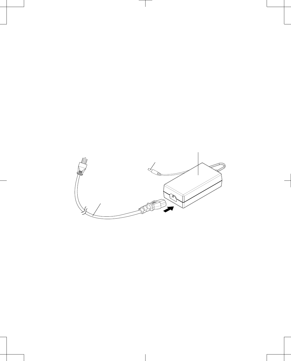
To connect and use the power supply and cord:
1. Connect the socket end of the mains power cord to the 3-pin plug of the power supply (Figure 8).
2. Insert the DC end of the power supply cord into the power jack of the desired product.
3. Connect the mains power cord plug to an electrical outlet. The power indicator on the power supply
will turn solid green.
Power supply
DC end
Power cord
Figure 8. Connecting the power supply and cord.
Notes:
▪The mains power cord plug may differ based on region.
▪When the power supply is connected to a mains electrical outlet, power is on. To turn power off,
disconnect the power supply from the mains electrical outlet.
The electrical outlet should be located near the products. Position the power cord so that it will not be
stepped on and objects will not be placed on it. Always unplug the power cord when not in use.
wWarning: Do not pull directly on the power cord. There is a potential risk of burn, fire, and electric
shock, which may result in damage to the device and injury to the user. To safely remove the power
cord from an electrical outlet, grasp the plug and pull straight out from the electrical outlet.
8880CW 2013-03 English 19
Filename Date Time
UC200xxxxxx EN
7 x 9 inches (178 mm x 229 mm)
Medtronic
Confidential
HardwareShortManual.xsl - HardwareShortTemplate.fm
Template version: 07-06-2012
M937825A001 Rev X 2013- 03

Connecting to the USB port
To connect a printer USB cable to the programmer:
1. Correctly orient the printer USB cable plug in relation to the USB port on the programmer.
2. Insert the plug into the port.
Note: Compatible printer drivers are PCL3, PCL3e, PCL4, PCL5C (color), PCL5e, PS2, PS2 (color),
PS3. Consult your printer manufacturer to determine the correct page description language, eg, PS
(PostScript®) or PCL® (Printer Command Language).
To connect a USB flash drive to the programmer:
1. Correctly orient the USB flash drive in relation to the USB port on the programmer.
2. Insert the USB flash drive into the port.
Using the docking station
Place the docking station on a reliable surface before using. The docking station leg can be adjusted to
a desired angle.
Notes:
▪The cradle and legs of the docking station can be separated to allow the cradle to be VESA-
mounted.
▪Mains electricity through the power supply must be connected to the docking station in order to use
connected equipment.
▪The USB port on the docking station should only be used to connect a USB flash drive, the USB
system connector cable, or a printer USB cable.
For instructions on using the docking station, see Table 4.
Table 4. Using the docking station
Procedure: Do this:
To dock the programmer (Figure 9): 1. With the screen of the programmer facing outwards,
place the bottom of the programmer into the cradle of
the docking station so that the docking connector
and docking pins align.
2. Press the programmer into the back of the docking
station until the docking station tab snaps over the
programmer to hold it in place.
To undock the programmer (Figure 9): 1. Lift the tab of the docking station until it releases the
programmer.
2. Lift the programmer from the docking station.
To connect the USB system connector cable to the
docking station:
1. Make sure the docking station is powered.
2. See "Connecting to and disconnecting from the
programmer" on page 23.
To connect a USB flash drive to the docking station: 1. Make sure the docking station is powered.
2. Correctly orient the USB flash drive in relation to the
USB port on the docking station.
3. Insert the USB flash drive into the port.
20 English 8880CW 2013-03
Filename Date Time
UC200xxxxxx EN
7 x 9 inches (178 mm x 229 mm)
Medtronic
Confidential
HardwareShortManual.xsl - HardwareShortTemplate.fm
Template version: 07-06-2012
M937825A001 Rev X 2013- 03

Table 4. Using the docking station (continued)
Procedure: Do this:
To connect a printer USB cable to the docking station
(Figure 10):
Note: Compatible printer drivers are PCL3, PCL3e,
PCL4, PCL5C (color), PCL5e, PS2, PS2 (color), PS3.
Consult your printer manufacturer to determine the
correct page description language, eg, PS (PostScript) or
PCL (Printer Command Language).
1. Make sure the docking station is powered.
2. Correctly orient the printer USB cable plug in relation
to the USB port on the docking station.
3. Insert the plug into the port.
To connect an Ethernet cable to the docking station
(Figure 10):
Note: An Ethernet port may not be available on all
docking stations.
1. Make sure the docking station is powered.
2. Correctly orient the Ethernet cable plug in relation to
the Ethernet port of the docking station.
3. Insert the plug into the port until it snaps into place. A
flashing green LED in the Ethernet socket indicates a
10 Mbps connection, while a flashing yellow LED
indicates a 100 Mbps connection.
Note: The connection speed is dependent on the
external network hardware and wiring and is not user
configurable. The programmer will negotiate the fastest
connection available when connected to the Ethernet
network
To connect a VGA cable from an external monitor to the
docking station, in order to display the programmer
image on an external monitor (Figure 10):
Note: A VGA output connection may not be available on
all docking stations.
1. Make sure the docking station is powered.
2. Correctly orient the VGA cable plug in relation to the
VGA output connection of the docking station. The
pins of the VGA cable plug should align with the
holes of the VGA output connection.
3. Firmly insert the plug into the connection.
4. Secure the screws of the plug to the connection.
Note: VGA output settings and resolution are not user
configurable.
To store the telemetry head on the docking station, when
the telemetry head is not in use (Figure 11):
1. Remove the plug from the accessory connector on
the back of the telemetry head.
2. Orient the telemetry head at a 90° angle to the back
leg of the docking station.
3. Place the accessory connector on the back of the
telemetry head over the accessory connector on the
back leg of the docking station.
4. Rotate the telemetry head downward 90° until it locks
into place.
8880CW 2013-03 English 21
Filename Date Time
UC200xxxxxx EN
7 x 9 inches (178 mm x 229 mm)
Medtronic
Confidential
HardwareShortManual.xsl - HardwareShortTemplate.fm
Template version: 07-06-2012
M937825A001 Rev X 2013- 03
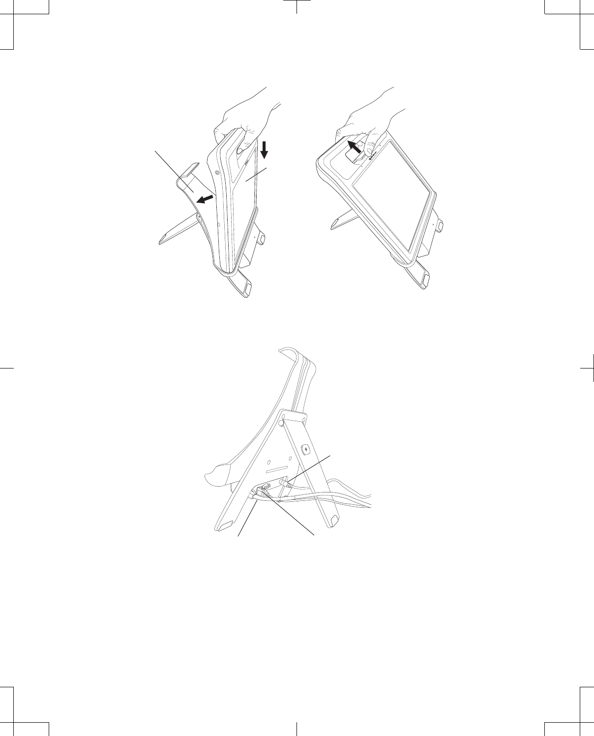
Docking station
Programmer
Figure 9. Docking and undocking the programmer.
Ethernet cable Printer USB cable
Power cord
Figure 10. Docking station with cables attached.
22 English 8880CW 2013-03
Filename Date Time
UC200xxxxxx EN
7 x 9 inches (178 mm x 229 mm)
Medtronic
Confidential
HardwareShortManual.xsl - HardwareShortTemplate.fm
Template version: 07-06-2012
M937825A001 Rev X 2013- 03
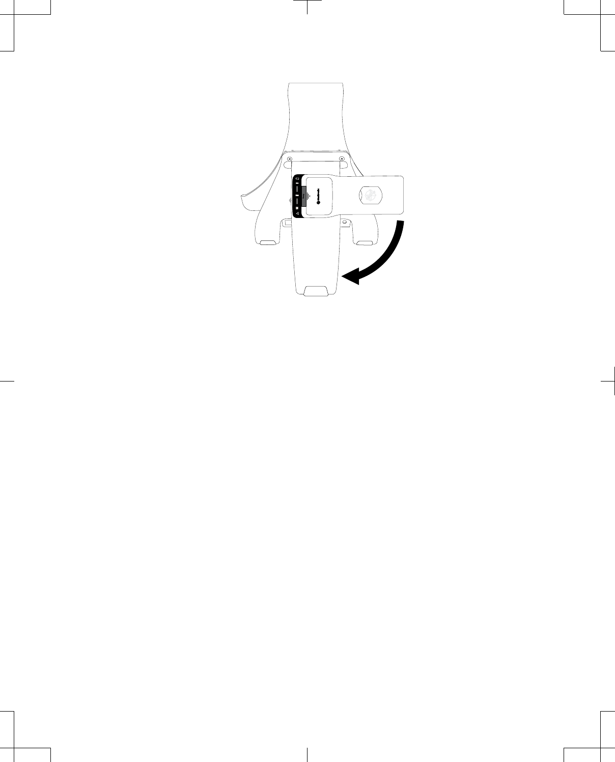
Figure 11. Storing the telemetry head on the back of the docking station.
Using the telemetry head
Connecting to and disconnecting from the programmer
The first time any telemetry head is used with a programmer, the telemetry head must be connected
using the Model 885010 USB System Connector Cable. Subsequent uses of the telemetry head with
that programmer can utilize Bluetooth wireless technology.
Note: A telemetry head that is connected to the programmer using the USB system connector cable will
take priority over other telemetry heads.
To connect the USB system connector cable:
1. Position the programmer and telemetry head within 1.83 m (6 ft) of each other.
2. Correctly orient the proprietary end of the cable in relation to the proprietary connector on the
telemetry head and insert the proprietary plug into the connector (Figure 12).
3. Correctly orient the USB end of the cable in relation to the USB port on the programmer (or docking
station if the programmer is docked) and insert the USB plug into the port (Figure 13 and Figure 14).
When the telemetry head is connected to the programmer via USB system connector cable, a
button showing a telemetry head with USB will appear towards the top right of the programmer
screen (Table 7 on page 37).
8880CW 2013-03 English 23
Filename Date Time
UC200xxxxxx EN
7 x 9 inches (178 mm x 229 mm)
Medtronic
Confidential
HardwareShortManual.xsl - HardwareShortTemplate.fm
Template version: 07-06-2012
M937825A001 Rev X 2013- 03
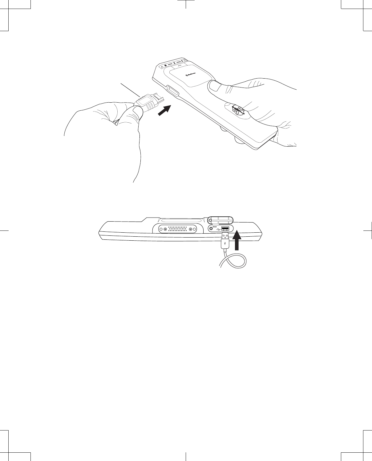
Proprietary plug
Figure 12. Connecting the USB system connector cable to the telemetry head.
Figure 13. Connecting the USB system connector cable to the programmer.
24 English 8880CW 2013-03
Filename Date Time
UC200xxxxxx EN
7 x 9 inches (178 mm x 229 mm)
Medtronic
Confidential
HardwareShortManual.xsl - HardwareShortTemplate.fm
Template version: 07-06-2012
M937825A001 Rev X 2013- 03
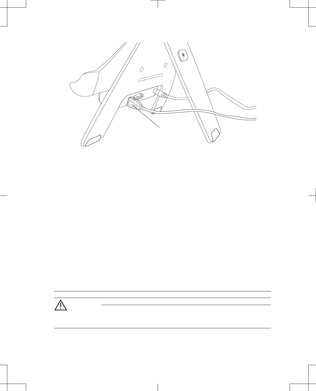
USB system connector cable
Figure 14. Connecting the USB system connector cable to the docking station.
To disconnect the USB system connector cable and switch to Bluetooth wireless technology:
1. Unplug the USB system connector cable from the programmer and the telemetry head.
The programmer will search for the telemetry head and may take up to 12 seconds to detect and
connect to the telemetry head using Bluetooth wireless technology.
2. Make sure the telemetry head is turned on and within range of the programmer (within 3 meters;
less than 10 feet).
When the telemetry head is connected to the programmer via Bluetooth, a button showing a
telemetry head with Bluetooth will appear towards the top right of the programmer screen (Table 7
on page 37).
Turning the telemetry head on or off
To turn the telemetry head on, slide the Power button, then release.
To turn the telemetry head off, slide the Power button, hold for 2 seconds, then release.
Telemetry head LED indicators
The following table describes the LED indicators on the front of the telemetry head.
Table 5. Telemetry head LED indicators
LED indicator Behavior Description
Warning
Flashing amber for 5 seconds Communicate button has been pressed but has not
been enabled by the programmer.
Note: Two descending tones sound from the
telemetry head.
8880CW 2013-03 English 25
Filename Date Time
UC200xxxxxx EN
7 x 9 inches (178 mm x 229 mm)
Medtronic
Confidential
HardwareShortManual.xsl - HardwareShortTemplate.fm
Template version: 07-06-2012
M937825A001 Rev X 2013- 03
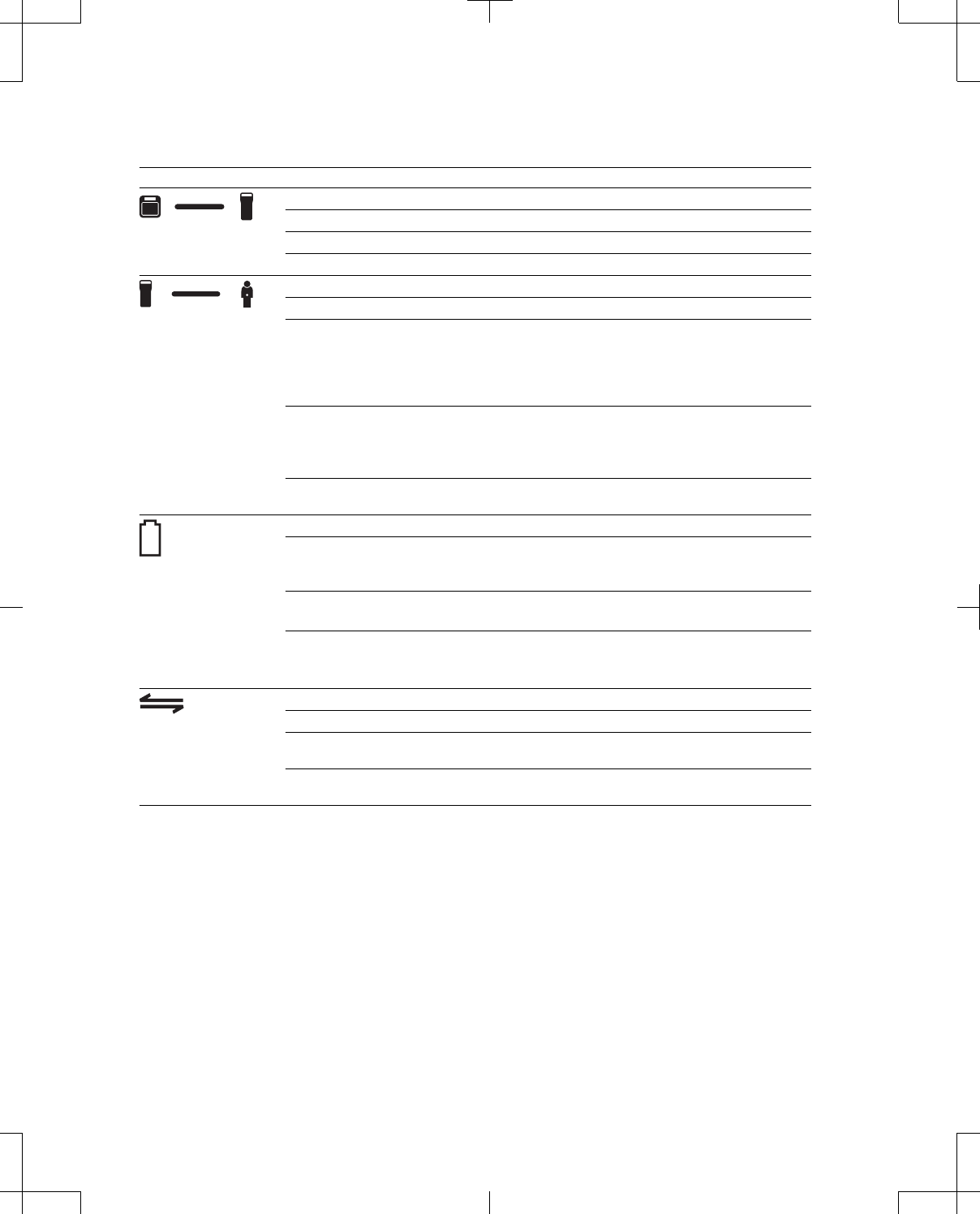
Table 5. Telemetry head LED indicators (continued)
LED indicator Behavior Description
Programmer status
Solid green for 3 seconds Telemetry head has been turned on.
Solid green Telemetry head is connected to the programmer.
Flashing amber Telemetry head is not connected to the programmer.
Implantable device status
Solid green for 3 seconds Telemetry head has been turned on.
Flashing green Telemetry head is successfully communicating with
an implantable device.
Note: When the telemetry head has completed
communication with an implantable device, a tone
repeats twice and the LED indicator turns off.
Flashing amber Telemetry head is attempting to communicate with
an implantable device, but is unable to detect the
implantable device.
Note: A single tone sounds from the telemetry head.
Off Telemetry head is not attempting to communicate
with an implantable device.
Battery status
Flashing green for 10 seconds Telemetry head has been turned on.
Battery level is acceptable and all telemetry head
functions are enabled.
Flashing amber Telemetry head has been turned on.
Batteries should be replaced soon.
Flashing red Telemetry head has been turned on.
Batteries should be replaced immediately.
Communicate button is disabled.
Communicate button
Solid green for 3 seconds Telemetry head has been turned on.
Flashing green Communicate button has been enabled by the
programmer.
Off Communicate button has not been enabled by the
programmer.
Initiating telemetry
If the Communicate button has been enabled by the programmer, when the Communicate button is
pressed the telemetry head sends a request to the programmer to initiate a telemetry session with the
implantable device. For more information on enabling the Communicate button and on initiating
telemetry with an implantable device, refer to the appropriate programmer guide for the device and
therapy.
#Caution: Do not attempt telemetry near equipment that may generate electromagnetic interference
(EMI). EMI can interfere with programmer telemetry. If EMI disrupts programming, move the
programmer away from the likely source of EMI. Examples of sources of EMI are magnetic
resonance imaging (MRI), lithotripsy, computer monitors, cellular telephones, motorized
26 English 8880CW 2013-03
Filename Date Time
UC200xxxxxx EN
7 x 9 inches (178 mm x 229 mm)
Medtronic
Confidential
HardwareShortManual.xsl - HardwareShortTemplate.fm
Template version: 07-06-2012
M937825A001 Rev X 2013- 03
wheelchairs, x-ray equipment, and other monitoring equipment. Interrupting telemetry can result in
incorrect or incomplete programming.
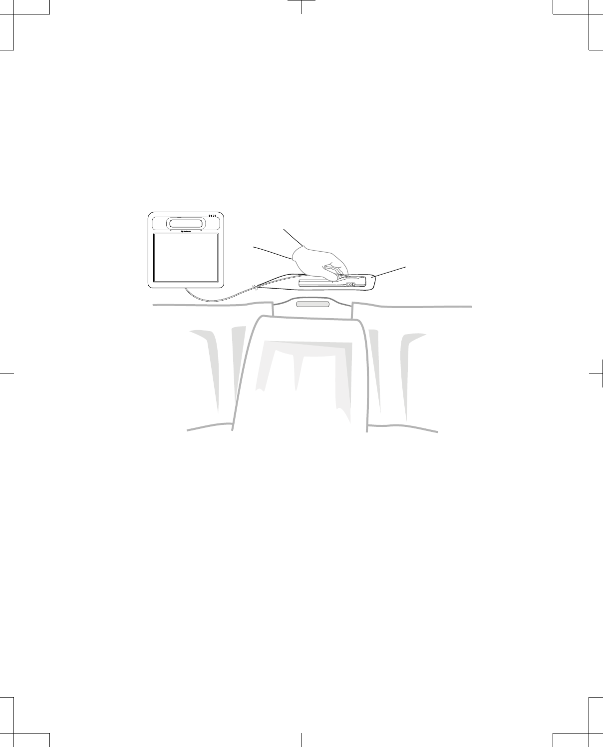
Positioning the telemetry head in a sterile field
wWarning: To use the nonsterile programmer system components in a sterile field, place a sterile
barrier between the patient and system components to prevent infection. Do not sterilize any
components of the programmer system. Sterilization may damage the components.
Figure 15 and Figure 16 demonstrate proper positioning of the telemetry head in a sterile field.
Sterile barrier
Figure 15. Telemetry head within a sterile field connected to a programmer, patient supine.
8880CW 2013-03 English 27
Filename Date Time
UC200xxxxxx EN
7 x 9 inches (178 mm x 229 mm)
Medtronic
Confidential
HardwareShortManual.xsl - HardwareShortTemplate.fm
Template version: 07-06-2012
M937825A001 Rev X 2013- 03

Sterile barrier
Figure 16. Telemetry head using Bluetooth wireless technology within sterile field, patient supine.
Programmer function overview
Note: Figures showing the programmer screen are representative. What is displayed on the actual
programmer screen may differ slightly.
Turning the programmer on
To turn the programmer on, press and release the Power button on the side of the programmer
(Figure 17).
When the programmer is turned on, white text will appear on the programmer screen prior to a welcome
screen being displayed. The programmer desktop will load within 60 seconds.
Note: The first time the programmer is used, the battery should be installed and mains electricity
through the power supply should be connected for at least 4 hours to charge the battery. See "Installing
or removing the programmer battery" on page 52 and "Connecting the power supply and cord" on
page 19 for instructions.
#Caution: Check the power status of the programmer before starting a programming session. Loss of
power during a programming session will reinitialize the programmer and can lead to a loss of data
and/or inability to program.
28 English 8880CW 2013-03
Filename Date Time
UC200xxxxxx EN
7 x 9 inches (178 mm x 229 mm)
Medtronic
Confidential
HardwareShortManual.xsl - HardwareShortTemplate.fm
Template version: 07-06-2012
M937825A001 Rev X 2013- 03
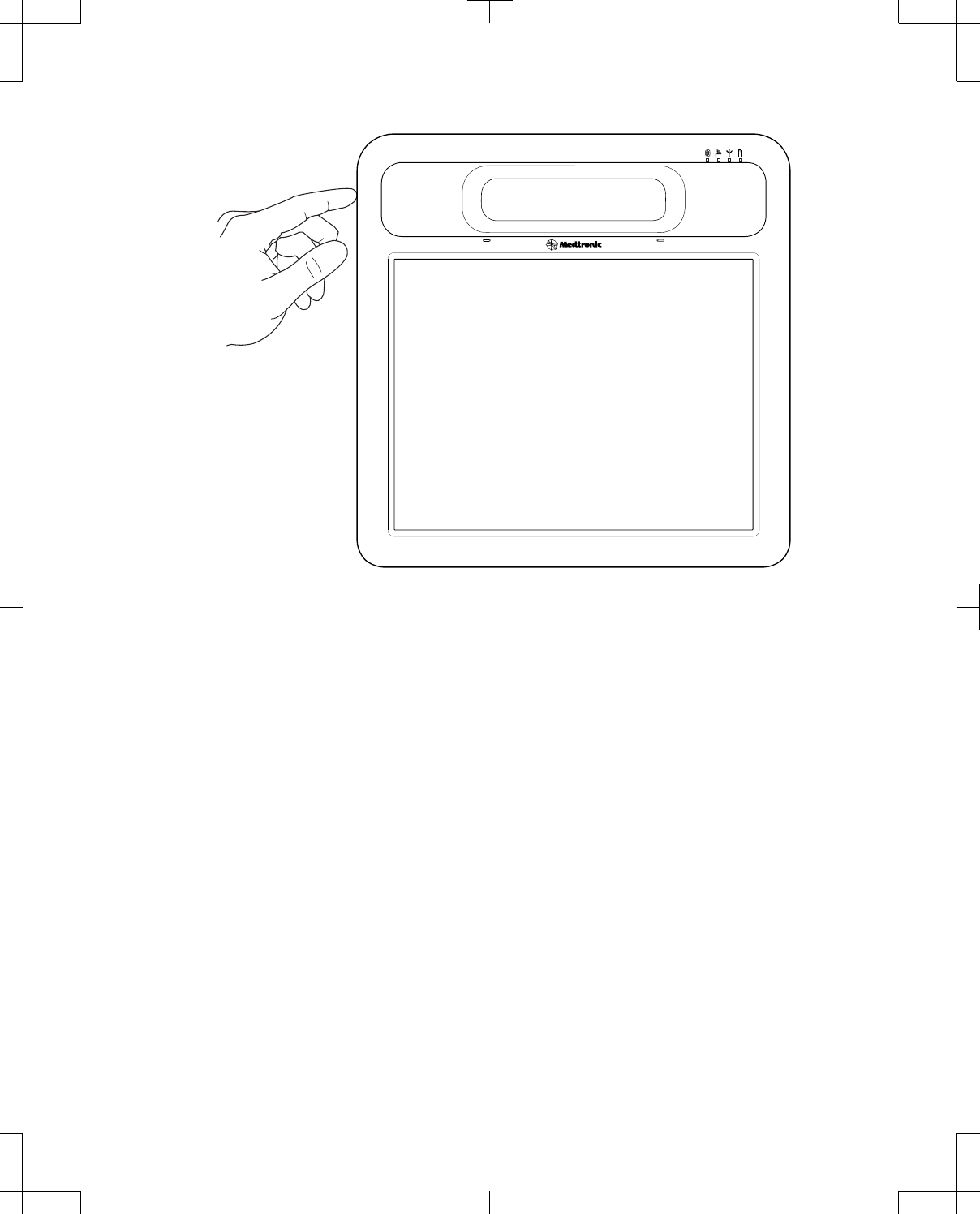
Figure 17. Turning the programmer on.
Data entry using the programmer touchscreen
The touchscreen is used to navigate, display status, and enter data. The stylus pen that is packaged
with the programmer or a finger can be used to make contact with the touchscreen. Only touch 1 point
on the touchscreen at a time. Do not use sharp objects (eg, pencils, pens, paper clips) on the
touchscreen. The stylus pen can be locked in place on the back of the programmer when not in use
(Figure 3 on page 14).
When entering data, most values are accepted through the following controls:
▪Drop-down list—A list of values appears when the arrow on the right side of a drop-down list is
pressed. Enter data by pressing a value.
8880CW 2013-03 English 29
Filename Date Time
UC200xxxxxx EN
7 x 9 inches (178 mm x 229 mm)
Medtronic
Confidential
HardwareShortManual.xsl - HardwareShortTemplate.fm
Template version: 07-06-2012
M937825A001 Rev X 2013- 03
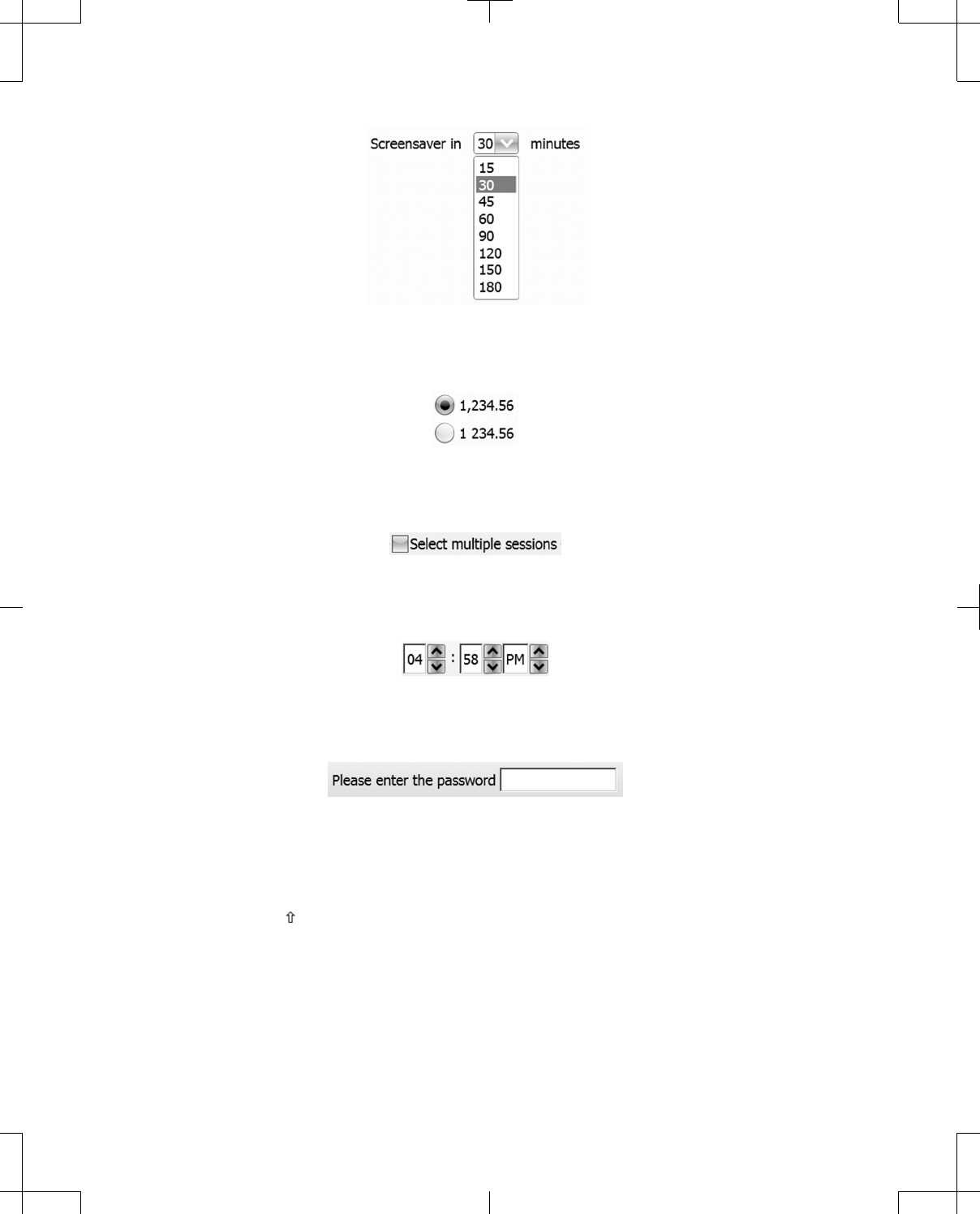
Figure 18. Drop-down list example.
▪Radio button—Press the radio button next to the desired value.
Figure 19. Radio button example.
▪Checkbox—Press the checkbox to make a selection.
Figure 20. Checkbox example, not selected.
▪Arrow buttons—Press the up or down arrow to change the value.
Figure 21. Arrow buttons example.
▪Input box or button—A keyboard or keypad appears when the input box or button is pressed.
Figure 22. Input box example.
▪Keyboard—The unshifted keyboard appears when the stylus contacts an input button or box that
requires alphanumeric input. To enter data, a text cursor will appear, then press individual
characters.
–Shift Arrow ( )—Changes the keyboard from lowercase to uppercase and makes other
characters available.
–Lock—Locks the keyboard in uppercase or lowercase mode.
30 English 8880CW 2013-03
Filename Date Time
UC200xxxxxx EN
7 x 9 inches (178 mm x 229 mm)
Medtronic
Confidential
HardwareShortManual.xsl - HardwareShortTemplate.fm
Template version: 07-06-2012
M937825A001 Rev X 2013- 03
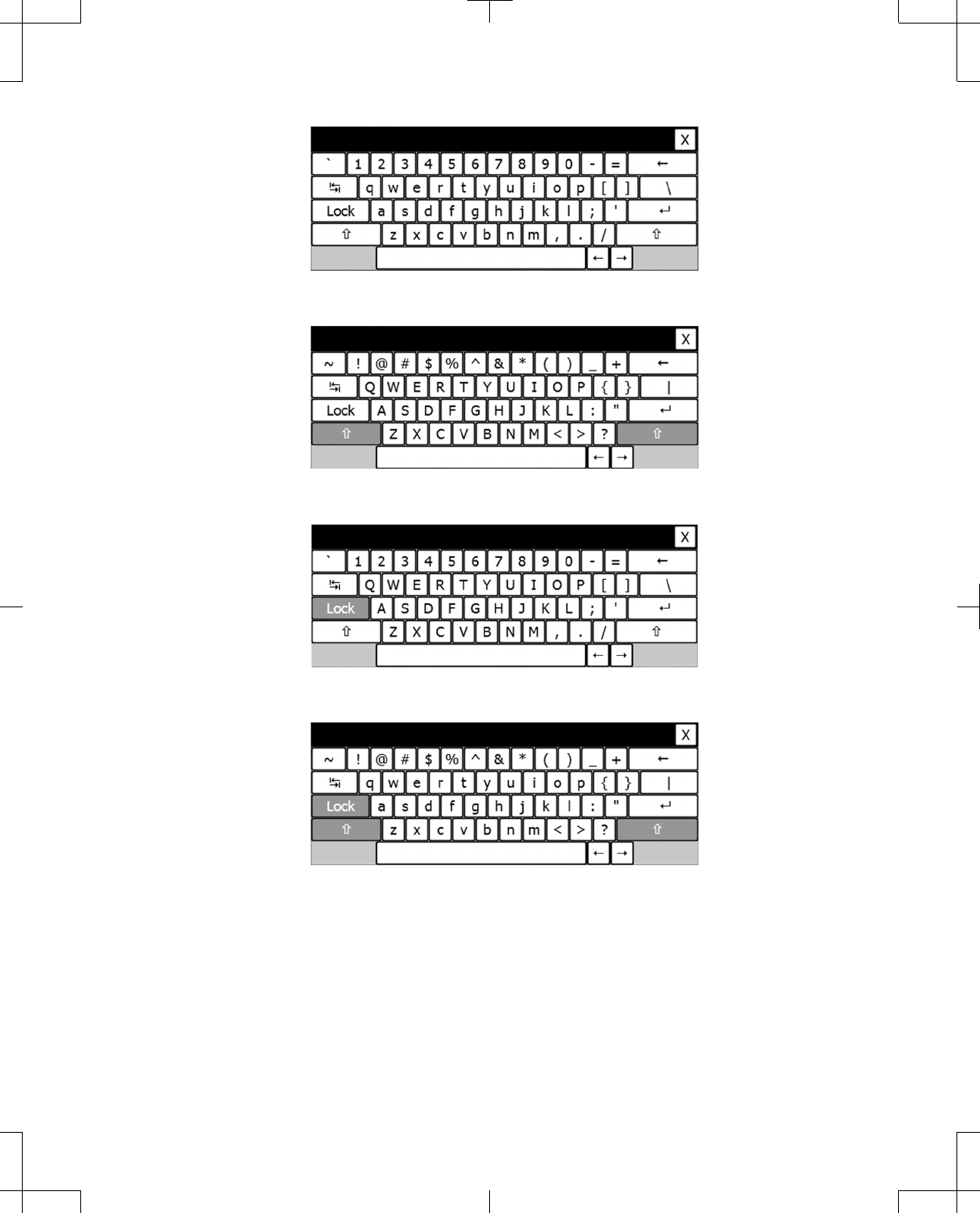
Figure 23. Unshifted keyboard.
Figure 24. Shifted keyboard.
Figure 25. Locked keyboard.
Figure 26. Shifted and locked keyboard.
▪Numeric keypad—The keypad appears when the stylus touches an input button or box that
requires numeric input. To enter data, press the input field, a text cursor will appear, then press
individual characters.
8880CW 2013-03 English 31
Filename Date Time
UC200xxxxxx EN
7 x 9 inches (178 mm x 229 mm)
Medtronic
Confidential
HardwareShortManual.xsl - HardwareShortTemplate.fm
Template version: 07-06-2012
M937825A001 Rev X 2013- 03
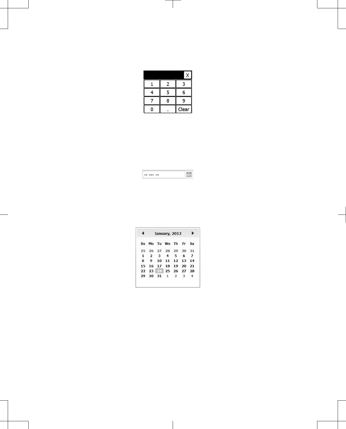
Note: Depending on the Number format setting, either a period or comma will appear on the
numeric keypad to be used as a decimal separator. A colon will appear on the numeric keypad when
the time of day needs to be entered.
Figure 27. Numeric keypad.
▪Date entry—A field that requires a date entry is indicated by a Calendar button or a calendar
display.
To set the Date:
1. If needed, press the Calendar button to open the date entry control to select the date (Figure 28).
Figure 28. Calendar button.
2. Press the month and year that is displayed between the left and right arrows at the top of the
calendar display to change the year or month (Figure 29).
Note: When pressed, the left arrow will move the calendar back a month and the right arrow will
move the calendar forward a month.
Figure 29. Calendar display example.
3. Press the year that is displayed between the left and right arrows at the top of the calendar to
change the decade (Figure 30).
32 English 8880CW 2013-03
Filename Date Time
UC200xxxxxx EN
7 x 9 inches (178 mm x 229 mm)
Medtronic
Confidential
HardwareShortManual.xsl - HardwareShortTemplate.fm
Template version: 07-06-2012
M937825A001 Rev X 2013- 03
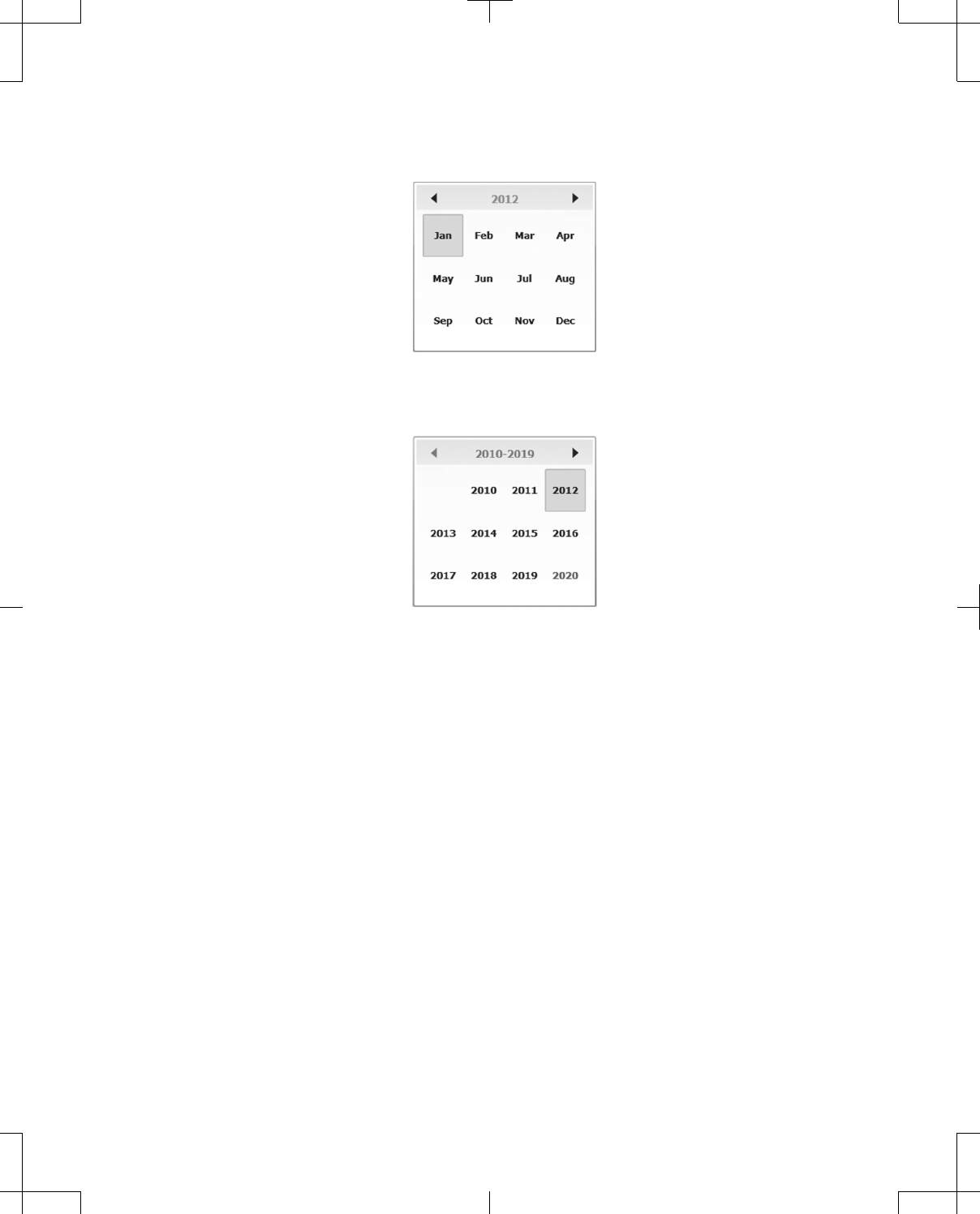
Note: When pressed, the left arrow will move the calendar back a year and the right arrow will move
the calendar forward a year.
Figure 30. Month display example.
4. Press the left and right arrows to change the decade (Figure 31).
Figure 31. Year display example.
5. Press the year (Figure 31).
6. Press the month (Figure 30).
7. Press the day of the month (Figure 29).
Configure initial user settings
The first time the programmer is turned on, user settings for Language, Number format, Date and
time, and Patient data security need to be configured and Contact information for the programmer
needs to be entered before the programmer desktop and therapy applications can be accessed.
The user settings and Contact information can be accessed again later, see "Managing the
programmer system" on page 40.
Note: If the programmer is turned off before all user settings screens are completed, no user settings
will be retained. The next time the programmer is turned on, user settings will be displayed again and
will need to be configured.
8880CW 2013-03 English 33
Filename Date Time
UC200xxxxxx EN
7 x 9 inches (178 mm x 229 mm)
Medtronic
Confidential
HardwareShortManual.xsl - HardwareShortTemplate.fm
Template version: 07-06-2012
M937825A001 Rev X 2013- 03

Table 6. Configuring initial user settings
Procedure: Do this:
Language
To change a Language setting: Press the radio button next to the desired language.
To move to the next screen: Press the Next button.
Number format
To change the Number format for date, time, and
numeric values:
Press the radio button next to the desired formats.
To move to the next screen: Press the Next button.
Date and time
To set the Date: Follow the instructions in "Data entry using the
programmer touchscreen" on page 29.
To set the Time: 1. Press the up or down arrow next to the hour.
2. Press the up or down arrow next to the minute.
3. If needed, press the up or down arrow next AM or
PM.
To move to the next screen: Press the Next button.
Patient data security
To enable Patient data security:
Note: If Patient data security is enabled, a password
must be entered the first time patient data are requested
after the programmer is turned on. If Patient data
security is enabled, only patient data from the current
programming session can be accessed without the
password.
Press the Yes, enable Patient Data Security radio
button.
To enter a Password and to Confirm Password: 1. Press the Password input box and use the keyboard
to select characters.
2. Press the Confirm Password input box and use the
keyboard to select characters that match the
Password.
Notes:
• There are no rules for setting a password, such as
minimum number of characters or use of numbers.
• The Next button will be disabled if either password
input box is empty.
• If the Password and Confirm Password do not
match, a message will appear after the Next button is
pressed.
To move to the next screen: Press the Next button.
Contact information
To enter Contact information: Press the input boxes and use the keyboard.
Note: Clinic, Address, and Contact are required data.
The Next button will be disabled until data is entered.
To move to the next screen: Press the Next button.
Review settings After the Contact information screen, a summary of the
selected user settings will display. Review the settings.
To return to the user settings screens: Press the Previous button.
34 English 8880CW 2013-03
Filename Date Time
UC200xxxxxx EN
7 x 9 inches (178 mm x 229 mm)
Medtronic
Confidential
HardwareShortManual.xsl - HardwareShortTemplate.fm
Template version: 07-06-2012
M937825A001 Rev X 2013- 03

Table 6. Configuring initial user settings (continued)
Procedure: Do this:
If the user settings have been reviewed and are
acceptable:
Press the Next button.
Programmer restart
To connect the telemetry head to the programmer: Follow the instructions in "Connecting to and
disconnecting from the programmer" on page 23.
Note: The programmer will need to restart to apply the
user settings. When the programmer starts, it will attempt
to connect to a telemetry head. The first time that any
telemetry head is used with a programmer, the telemetry
head must be connected using the Model 885010 USB
System Connector Cable. Subsequent uses of the
telemetry head with that programmer can utilize
Bluetooth wireless technology.
To have the programmer restart: Press the OK button.
Overview of programmer desktop
Note: When the programmer is turned on, white text will appear on the programmer screen prior to a
welcome screen being displayed. The programmer desktop will load within 60 seconds.
The programmer desktop is visible on the programmer screen when a programming session or Demo
Mode is not running. A programming session must be terminated to return to the programmer desktop.
From the programmer desktop (Figure 32):
▪a programming session with a device can be started.
▪Demo Mode can be started.
▪the programmer can be turned off or put into Standby.
▪the Control Panel and Messages are available.
8880CW 2013-03 English 35
Filename Date Time
UC200xxxxxx EN
7 x 9 inches (178 mm x 229 mm)
Medtronic
Confidential
HardwareShortManual.xsl - HardwareShortTemplate.fm
Template version: 07-06-2012
M937825A001 Rev X 2013- 03
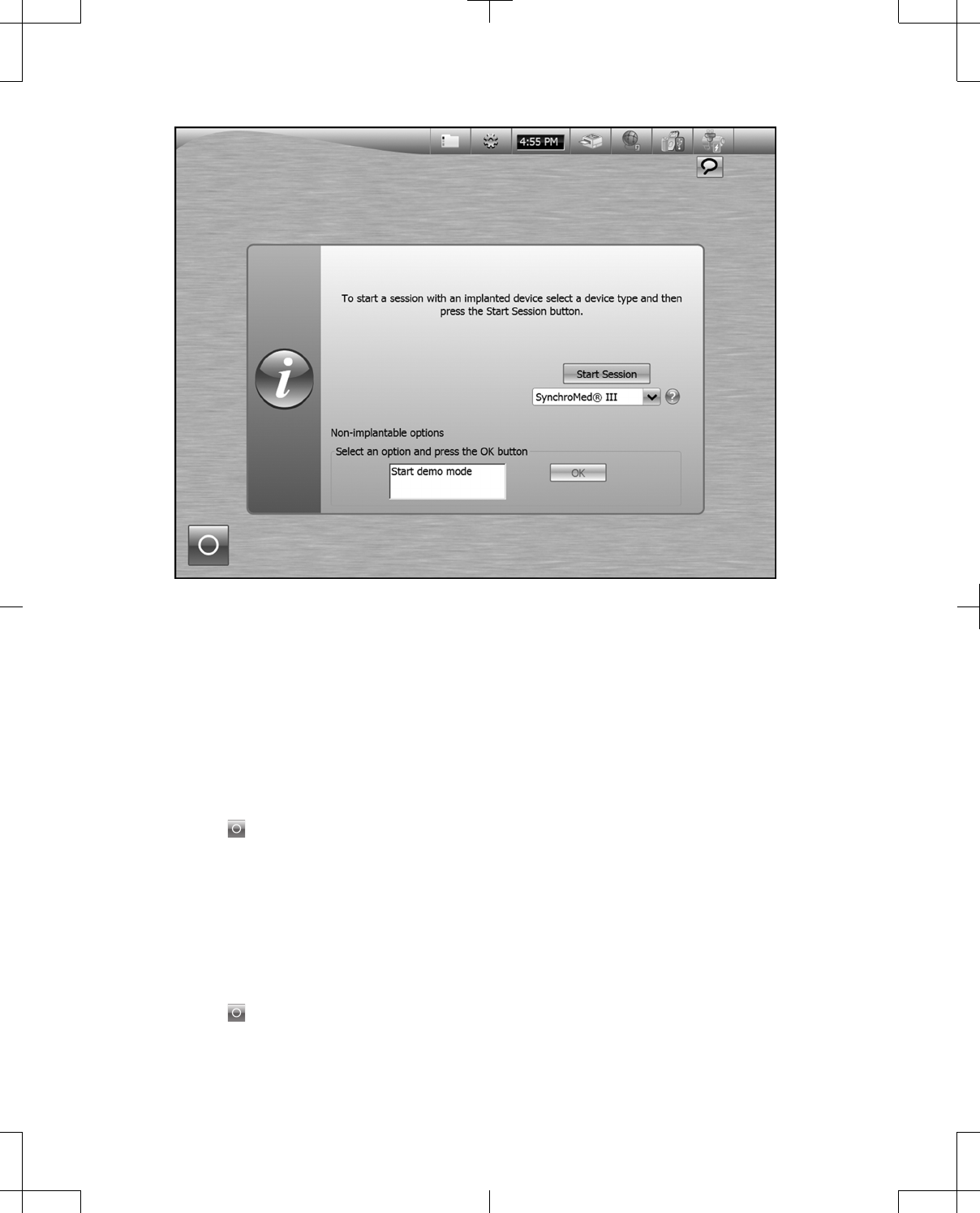
Figure 32. Programmer desktop upon start up.
For information about starting a programming session with a device and starting Demo Mode, refer to
the appropriate programmer guide.
The Control Panel and Messages are always visible at the top of the programmer screen, including
during a programming session and Demo Mode. See "Programmer Control Panel" on page 37.
Turning the programmer off
To turn the programmer off:
1. Exit any running application.
2. Press the button located on the desktop (Figure 32).
3. Press the Power Off button in the Shutdown window.
Note: The programmer will turn off if the Power button on the side of the programmer is pressed and
held down for 8 seconds. This is not the recommended way of turning off the programmer.
Putting the programmer into Standby
To put the programmer into Standby in between programming sessions:
1. Exit any running application.
2. Press the button located on the desktop (Figure 32).
3. Press the Standby button in the Shutdown window.
36 English 8880CW 2013-03
Filename Date Time
UC200xxxxxx EN
7 x 9 inches (178 mm x 229 mm)
Medtronic
Confidential
HardwareShortManual.xsl - HardwareShortTemplate.fm
Template version: 07-06-2012
M937825A001 Rev X 2013- 03
Note: The programmer continues to consume a small amount of power while in Standby.
To resume from Standby, press the Power button on the side of the programmer (Figure 1 on
page 13).
Note: It may take up to 15 seconds for the programmer to resume from Standby.
Programmer Control Panel
Note: Figures showing the programmer screen are representative. What is displayed on the actual
programmer screen may differ slightly.
The Control Panel is a series of buttons that are always available at the top right of the programmer
screen (Figure 32 on page 36). The Control Panel allows monitoring and management of the overall
programmer system, including the telemetry head, network connectivity, and printer connection.
Note: Only the Control Menu and Message buttons are available while an application is loading.
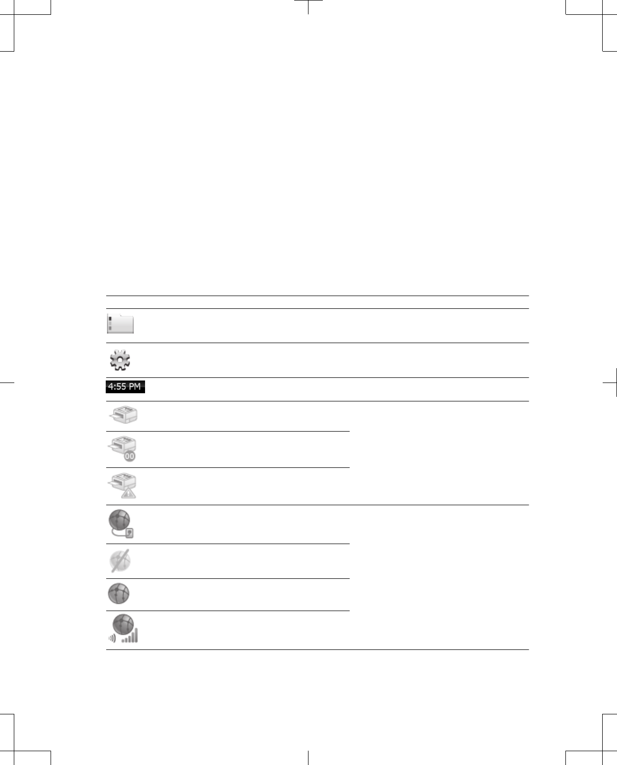
Table 7. Control Panel buttons
Button Status Description
Does not display status. Press the button to access the Patient Data
Center.
See "Patient Data Center" on page 45.
Does not display status. Press the button to expand the Control Menu
("Control Menu" on page 38).
Displays the current programmer time. Press the button to open the Date and Time
window.
Printer is idle. Press the button to open the Printer Settings
window.
Printer is active.
There is a printer error.
Programmer is connected to a network via
Ethernet cable.
Press the button to open the Network window.
Wireless network is not available.
Wireless network is available.
Programmer is connected to a wireless network.
8880CW 2013-03 English 37
Filename Date Time
UC200xxxxxx EN
7 x 9 inches (178 mm x 229 mm)
Medtronic
Confidential
HardwareShortManual.xsl - HardwareShortTemplate.fm
Template version: 07-06-2012
M937825A001 Rev X 2013- 03
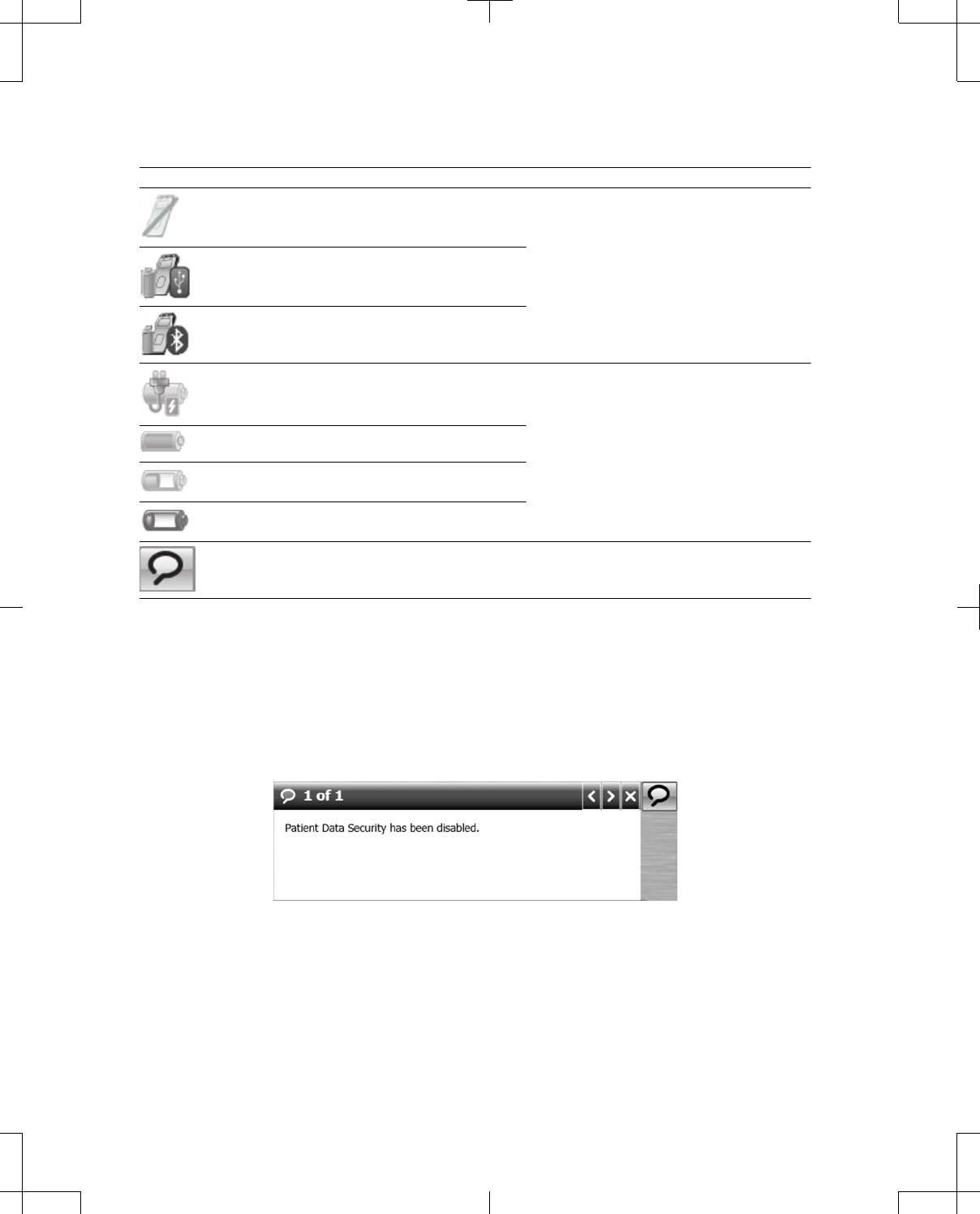
Table 7. Control Panel buttons (continued)
Button Status Description
Telemetry head is not connected. Press the button to open the Telemetry Head
window.
Telemetry head is connected via USB system
connector cable (button also displays the battery
status of the telemetry head).
Telemetry head is connected via Bluetooth
(button also displays the battery status of the
telemetry head).
Programmer is using the power supply and the
battery is charged (green) or the battery is
charging (orange).
Press the button to open the Power window.
Programmer is using battery power and the
battery is charged (green).
Programmer is using battery power and the
battery is low (orange).
Programmer is using battery power and the
battery is critically low (red).
Does not display status. Press the button to expand the Message
window.
See "Messages" for more information.
Messages
The Message window will automatically expand to present low priority alerts, such as status on printing
and programmer power (Figure 33).
Press the left or right arrow buttons to change messages. To close the Message window, press the X or
Message button.
Figure 33. Expanded Message window.
Control Menu
The Control Menu displays status and allows management of the following:
▪Date and Time
38 English 8880CW 2013-03
Filename Date Time
UC200xxxxxx EN
7 x 9 inches (178 mm x 229 mm)
Medtronic
Confidential
HardwareShortManual.xsl - HardwareShortTemplate.fm
Template version: 07-06-2012
M937825A001 Rev X 2013- 03
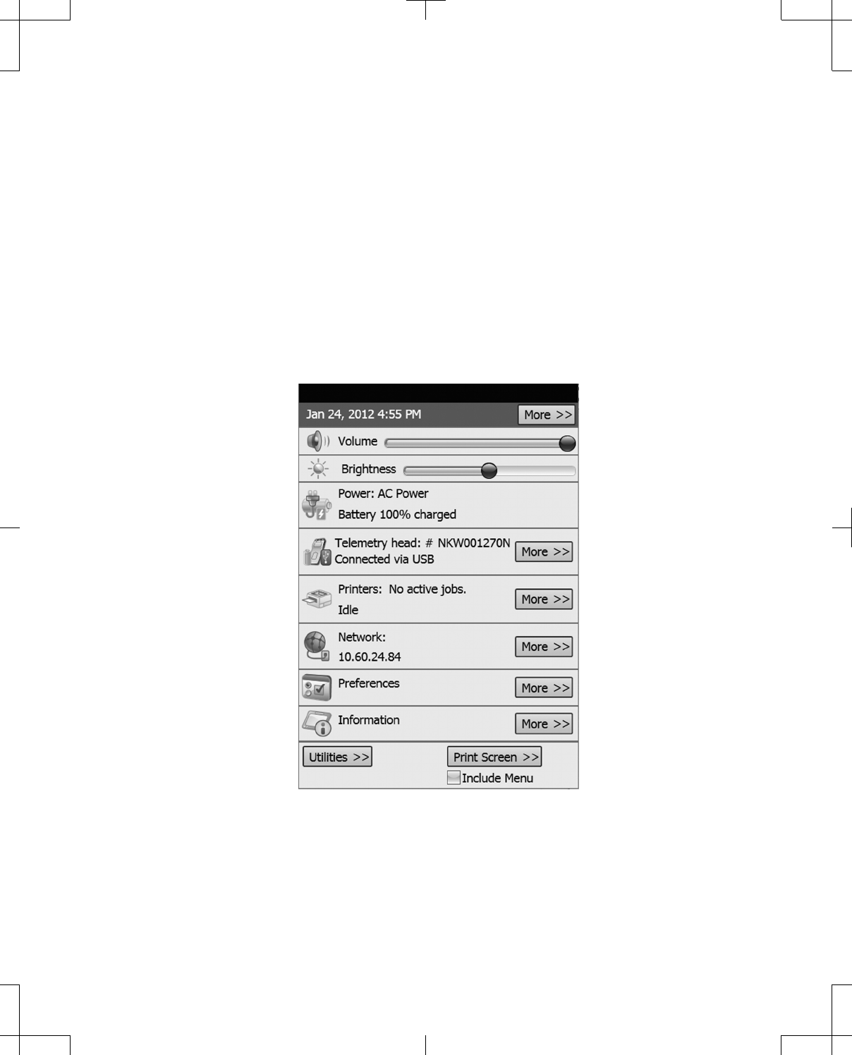
▪Volume (access through Control Menu only)
▪Brightness (access through Control Menu only)
▪Power (status only)
▪Telemetry head (status only)
▪Printers
▪Network
▪Preferences (access through Control Menu only)
▪Information (access through Control Menu only)
▪Utilities (access through Control Menu only)
▪Print screen (access through Control Menu only)
Figure 34. Expanded Control Menu.
More buttons will open windows for the corresponding panel items when pressed.
To close the Control Menu, press any area on the programmer screen outside the Control Menu.
8880CW 2013-03 English 39
Filename Date Time
UC200xxxxxx EN
7 x 9 inches (178 mm x 229 mm)
Medtronic
Confidential
HardwareShortManual.xsl - HardwareShortTemplate.fm
Template version: 07-06-2012
M937825A001 Rev X 2013- 03
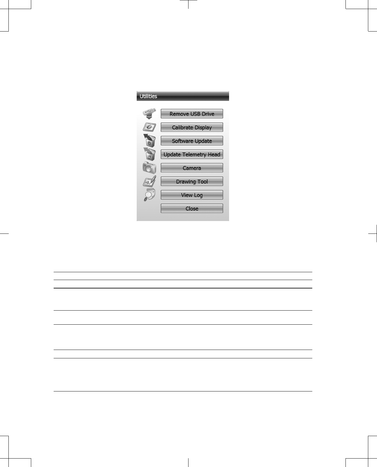
Utilities
Press the Utilities button in the Control Menu to open the Utilities window (Figure 35).
The Utilities window provides access to miscellaneous functions on the programmer.
Figure 35. Utilities window.
Managing the programmer system
Table 8. Managing the programmer system
Procedure: Do this:
Date and Time
To change the date or time: Open the Date and Time window.
Note: The programmer time cannot be changed while in
a programming session.
To set the Date: Follow the instructions in "Data entry using the
programmer touchscreen" on page 29.
To set the Time: 1. Press the up or down arrow next to the hour.
2. Press the up or down arrow next to the minute.
3. If needed, press the up or down arrow next to AM or
PM.
Volume
To adjust the Volume of the programmer: Press and drag the circle on the slider (Figure 34 on
page 39).
Note: When the circle is released, the volume will
immediately set and a beep will sound that is reflective of
the volume setting.
40 English 8880CW 2013-03
Filename Date Time
UC200xxxxxx EN
7 x 9 inches (178 mm x 229 mm)
Medtronic
Confidential
HardwareShortManual.xsl - HardwareShortTemplate.fm
Template version: 07-06-2012
M937825A001 Rev X 2013- 03

Table 8. Managing the programmer system (continued)
Procedure: Do this:
Brightness
To adjust the Brightness of the touchscreen:
Note: The brightness setting will be reset once the
programmer is turned off and on again.
Press and drag the circle on the slider (Figure 34 on
page 39).
Telemetry Head
To view telemetry head information such as serial
number and software version:
Open the Telemetry Head window.
Printers
To view a list of pending print jobs: Open the Printer Settings window.
To cancel a print job: 1. Open the Printer Settings window.
2. Press the desired print job row.
3. Press the Cancel Job button.
To set a printer as the default: 1. Open the Printer Settings window.
2. Select the desired printer from the drop-down list.
3. Press the Set as Default button.
To print a test page on a printer:
Note: The test page should contain a list of every
language available on the programmer and all characters
from the keyboard and numeric keypad.
1. Open the Printer Settings window.
2. Select the connected printer from the drop-down list.
3. Press the Print Test Page button.
Print Screen
To print the programmer screen: 1. Open the Control Menu.
2. Press the Print Screen button.
Note: To print the Control Menu, press the Include
Menu checkbox before pressing the Print Screen
button.
3. Select the connected printer from the Printer drop-
down list.
4. Select the desired number of Copies from the drop-
down list.
5. Select the desired Color option by pressing the radio
button.
6. Select the desired Paper size from the drop-down
list.
7. Press the Print button.
Note: Programmer screens are printed to landscape
orientation.
Network
Wireless Network
To disable the capability of the programmer to connect to
a wireless network:
1. Open the Network window.
2. Press the Wireless tab.
3. Press the Disable wireless radio radio button.
To enable the capability of the programmer to connect to
a wireless network:
1. Open the Network window.
2. Press the Wireless tab.
3. Press the Enable wireless radio radio button.
To connect to a wireless network that has been detected
by the programmer:
1. Open the Network window.
2. Press the Wireless tab.
3. Press the network row in the list.
4. Press the Connect button.
8880CW 2013-03 English 41
Filename Date Time
UC200xxxxxx EN
7 x 9 inches (178 mm x 229 mm)
Medtronic
Confidential
HardwareShortManual.xsl - HardwareShortTemplate.fm
Template version: 07-06-2012
M937825A001 Rev X 2013- 03

Table 8. Managing the programmer system (continued)
Procedure: Do this:
To edit the details of a wireless network: 1. Open the Network window.
2. Press the Wireless tab.
3. Press the network row in the list.
4. Press the Edit button.
To delete a wireless network from the programmer: 1. Open the Network window.
2. Press the Wireless tab.
3. Press the network row in the list.
4. Press the Delete button.
To connect to a wireless network manually: 1. Open the Network window.
2. Press the Wireless tab.
3. Press the Connect Manually button.
Network Settings (For Ethernet, if an Ethernet port is available on the docking station.)
To enter IP settings manually: 1. Open the Network window.
2. Press the Network Settings tab.
3. Press the Use the following IP settings radio
button.
4. Press the IP address input box and use the keypad
to enter data.
5. Press the Subnet Mask input box and use the
keypad to enter data.
6. Press the Default gateway input box and use the
keypad to enter data.
7. Press the Save button.
To enter DNS server addresses manually: 1. Open the Network window.
2. Press the Network Settings tab.
3. Press the Use the following DNS server
addresses radio button.
4. Press the Preferred DNS Server input box and use
the keypad to enter data.
5. Press the Secondary DNS Server input box and use
the keypad to enter data.
6. Press the Save button.
Bluetooth
To enable Bluetooth:
Note: If Bluetooth is enabled, the programmer can
communicate wirelessly with the telemetry head or other
approved devices.
1. Open the Network window.
2. Press the Bluetooth tab.
3. Press the Enable Bluetooth Adapter radio button.
4. Restart the programmer.
To disable Bluetooth:
Note: If Bluetooth is disabled, the programmer and
telemetry head will need to be connected using the USB
system connector cable in order to communicate. The
programmer will not be able to communicate with other
approved devices that only use Bluetooth.
1. Open the Network window.
2. Press the Bluetooth tab.
3. Press the Disable Bluetooth Adapter radio button.
42 English 8880CW 2013-03
Filename Date Time
UC200xxxxxx EN
7 x 9 inches (178 mm x 229 mm)
Medtronic
Confidential
HardwareShortManual.xsl - HardwareShortTemplate.fm
Template version: 07-06-2012
M937825A001 Rev X 2013- 03

Table 8. Managing the programmer system (continued)
Procedure: Do this:
Email
To set up email:
Notes:
• Email settings must be set up in order to send reports
via email.
• Only outgoing email is supported.
• Consult your network documentation or IT department
to determine the correct settings for your location.
1. Open the Network window.
2. Press the Email tab.
3. Press the Outgoing server input box and enter data
using the keyboard.
4. Press the Port input box and enter data using the
keypad.
5. Press the User name input box and enter data using
the keyboard.
6. Press the Password input box and enter data using
the keyboard.
7. Press the Default return email address input box
and enter data using the keyboard.
8. If desired, press the Enable SSL checkbox.
9. Press the Save button.
Locations
To add a network location path:
Note: Network locations must be set up in order to save
reports to a network location.
1. Open the Network window.
2. Press the Locations tab.
3. Press the Location input box and enter a valid
network path using the keyboard.
4. Press the Add button.
To remove a network location from the list of Existing
Locations:
1. Open the Network window.
2. Press the Locations tab.
3. Press the location row.
4. Press the Delete button.
Preferences
To change a Language setting: 1. Open the Preferences window.
2. Press the Language tab.
3. Press the radio button next to the desired language.
4. Restart the programmer.
To change the amount of time that the programmer must
be inactive before the screen saver will activate:
1. Open the Preferences window.
2. Press the Time out tab.
3. Select from the drop-down list.
To enable Patient Data Security:
Note: If Patient data security is enabled, a password
must be entered the first time patient data are requested
after the programmer is turned on. If Patient data
security is enabled, only patient data from the current
programming session can be accessed without the
password.
1. Open the Preferences window.
2. Press the Patient Data Security tab.
3. Press the Enable Patient Data button.
4. Press the Password input box and use the keyboard
to select characters.
5. Press the Confirm Password input box and use the
keyboard to select characters that match the
Password.
6. Press the OK button.
Notes:
• There are no rules for setting a password, such as
minimum number of characters or use of numbers.
• If the Password and Confirm Password do not
match, a message will appear after the Next button is
pressed.
8880CW 2013-03 English 43
Filename Date Time
UC200xxxxxx EN
7 x 9 inches (178 mm x 229 mm)
Medtronic
Confidential
HardwareShortManual.xsl - HardwareShortTemplate.fm
Template version: 07-06-2012
M937825A001 Rev X 2013- 03

Table 8. Managing the programmer system (continued)
Procedure: Do this:
To change the Patient Data Security password: 1. Open the Preferences window.
2. Press the Patient Data Security tab.
3. Press the Change Password button.
4. Press the Old Password input box and use the
keyboard to enter the old password.
5. Press the New password input box and use the
keyboard to select characters.
6. Press the Confirm New Password input box and
use the keyboard to select characters that match the
new password.
7. Press the OK button.
If the Patient Data Security password is unknown: See "Resetting the Patient data security password" on
page 59.
To disable Patient Data Security: 1. Open the Preferences window.
2. Press the Patient Data Security tab.
3. Press the Disable Patient Data button.
4. Press the input box and use the keyboard to enter
the password.
5. Press the OK button.
To change the format for date, time, and numeric values: 1. Open the Preferences window.
2. Press the Format options tab.
3. Press the radio button next to the desired formats.
4. Restart the programmer.
Information
To view programmer information such as serial number,
software version, installed applications and contact
information:
Open the Information window.
To change contact information for the programmer: 1. Open the Information window.
2. Press the desired input box(es) and use the
keyboard to enter data.
3. Press the OK button.
Remove USB Drive
To safely remove an active USB flash drive from the
programmer:
1. Press the Control Menu button.
2. Press the Utilities button.
3. Press the Remove USB Drive button.
4. Firmly grasp the USB flash drive and pull it straight
out of the USB port.
Calibrate Display
For instructions on calibrating the touchscreen see "Calibrating the touchscreen" on page 57.
Software Update
Medtronic will make software updates available. Refer to the instructions provided with the software updates to
update the software on the programmer.
Update Telemetry Head
Medtronic will make software updates available. Refer to the instructions provided with the software updates to
update the software on the telemetry head.
44 English 8880CW 2013-03
Filename Date Time
UC200xxxxxx EN
7 x 9 inches (178 mm x 229 mm)
Medtronic
Confidential
HardwareShortManual.xsl - HardwareShortTemplate.fm
Template version: 07-06-2012
M937825A001 Rev X 2013- 03

Table 8. Managing the programmer system (continued)
Procedure: Do this:
Camera
To use the Camera on the back of the programmer to
capture images:
1. Press the Control Menu button.
2. Press the Utilities button.
3. Press the Camera button to open the Camera
control.
Note: For more information on the use of the Camera
control, refer to the appropriate programmer guide to see
if the Camera control is supported.
Drawing Tool
To draw lines on the active programmer screen: 1. Press the Control Menu button.
2. Press the Utilities button.
3. Press the Drawing Tool button.
Note: All functionality is disabled when the Drawing
Tool is open, except for Print Screen and Therapy
Stop (if supported by the application).
4. Press the Point Size button to select a different size
for the drawing function.
5. Press the Line button to select a different color for
the drawing function.
6. Press the Pen button to change the drawing function
to an eraser function.
7. Press the Trash button to clear the screen.
8. Press the X button to close the Drawing Tool.
Note: Any drawings on the screen will be cleared
when the Drawing Tool is closed.
View Log
To view a list of system logs for troubleshooting
purposes:
1. Press the Control Menu button.
2. Press the Utilities button.
3. Press the View Log button.
Patient Data Center
The Patient Data Center provides patient records for all patients who have had a programming session
on the programmer. The patient record includes all device and session data, as well as a Patient
Profile, which includes demographic information, notes, and imported files and images.
New patient records are created when a programming session is started and a device is interrogated.
The Patient Data Center also provides reports. Reports can be created to include data from a
particular patient session, from multiple patient sessions, or for multiple patients. Reports can be viewed
on the programmer screen, printed, sent via email, saved to a USB flash drive, or saved to a network
location. See "Reports" on page 49.
To access the Patient Data Center, press the associated button located on the Control Panel (Table 7
on page 37).
8880CW 2013-03 English 45
Filename Date Time
UC200xxxxxx EN
7 x 9 inches (178 mm x 229 mm)
Medtronic
Confidential
HardwareShortManual.xsl - HardwareShortTemplate.fm
Template version: 07-06-2012
M937825A001 Rev X 2013- 03
Patient Record Security
Facilities should take all necessary steps to protect the patient information contained on the
programmer consistent with governmental requirements and regulations related to the protection of
such information.
If Patient Data Security is enabled, the first time the Patient Data Center is accessed after the
programmer is turned on or returns from Standby mode, the password will need to be entered.
On subsequent entries, no password is required unless the Log Off button was used to exit the Patient
Data Center. Patient Data Security options can be accessed in the Control Menu, see "Managing the
programmer system" on page 40.
Press the X button to exit the Patient Data Center and remain logged in.
Note: If the programmer loses power or is turned off, the password will need to be entered to log back
into the Patient Data Center.
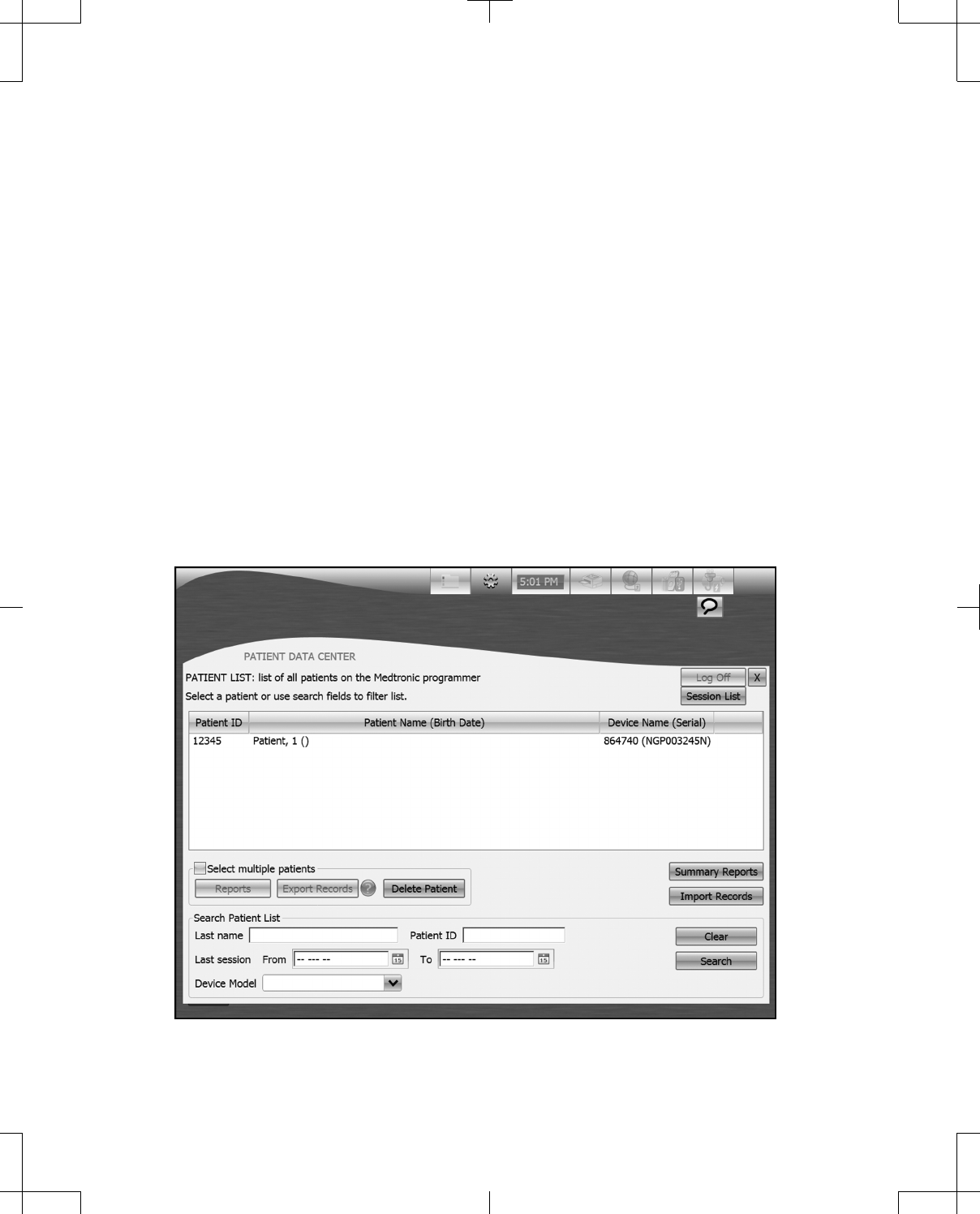
Patient List
When the Patient Data Center is accessed, the Patient List, a list of all patients who have a record on
the programmer is provided (Figure 36).
The Patient List button will display the Patient List when pressed.
Figure 36. Patient List screen from the Patient Data Center.
46 English 8880CW 2013-03
Filename Date Time
UC200xxxxxx EN
7 x 9 inches (178 mm x 229 mm)
Medtronic
Confidential
HardwareShortManual.xsl - HardwareShortTemplate.fm
Template version: 07-06-2012
M937825A001 Rev X 2013- 03

Note: Once the Select multiple patients checkbox has been pressed, the Reports, Export Records,
and Delete Patient buttons are enabled. One or more patients must be selected in order for the buttons
to function.
Search Patient List allows the list of patients to be filtered according to the search criteria entered.
To enter search criteria:
1. Press the Last name input box and enter the patient’s last name using the keyboard.
2. Press the Patient ID input box and enter the patient’s ID using the keyboard.
3. Press the Calendar buttons next to the From and To fields to enter the dates that the patient’s Last
session occurred between.
4. Select the patient’s Device Model from the drop-down list.
5. Press the Search button.
Notes:
▪Search fields that are left blank are interpreted as "all".
▪For any data entered for Last name or Patient ID, the search will return records with exact matches
or that begin with the entered data. The search is not case dependent.
▪If no To date is entered, the search returns records up to the present date.
▪If no From date is entered, the search returns all records up to and including the entered To date.
If no records are found matching the search criteria, No patients records found appears in the Patient
List.
To delete all search criteria that has been entered, press the Clear button.
Patient Profile
Press the patient's row in the Patient List to view the Patient Profile.
The Patient Profile includes basic demographic information such as the patient’s name, ID, sex, and
birth date. Press the Sessions tab to see a list of the patient’s sessions that have occurred on the
programmer. Press the Devices tab to see a list of devices the patient has. Press the Patient
Information tab to see contact information for the patient.
Session List
The Session List provides a list of all programming sessions that have occurred on the programmer
(Figure 37). Sessions are listed in order of most current.
The Session List button displays the Session List when pressed.
8880CW 2013-03 English 47
Filename Date Time
UC200xxxxxx EN
7 x 9 inches (178 mm x 229 mm)
Medtronic
Confidential
HardwareShortManual.xsl - HardwareShortTemplate.fm
Template version: 07-06-2012
M937825A001 Rev X 2013- 03
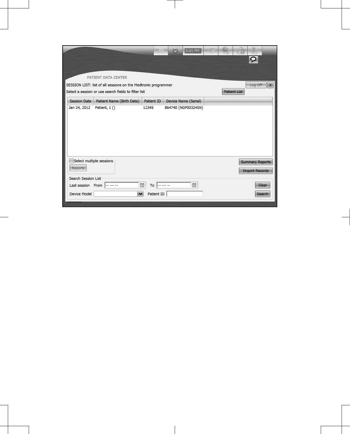
Figure 37. Session List screen from the Patient Data Center.
Note: Once the Select multiple patients checkbox has been pressed, the Reports button will be
enabled. One or more sessions must be selected in order for the buttons to function.
Search Session List allows the list of sessions to be filtered according to the entered search criteria.
To enter search criteria:
1. Press the Patient ID input box and enter the patient’s ID using the keyboard.
2. Using the Calendar buttons next to the From and To fields, enter the dates that the session
occurred between.
3. Select the patient’s Device Model from the drop-down list.
4. Press the Search button.
Notes:
▪Search fields that are left blank are interpreted as "all".
▪For any data entered for Patient ID, the search will return records with exact matches or that begin
with the entered data. The search is not case dependent.
▪If no To date is entered, the search returns records up to the present date.
▪If no From date is entered, the search returns all records up to and including the specified To date.
48 English 8880CW 2013-03
Filename Date Time
UC200xxxxxx EN
7 x 9 inches (178 mm x 229 mm)
Medtronic
Confidential
HardwareShortManual.xsl - HardwareShortTemplate.fm
Template version: 07-06-2012
M937825A001 Rev X 2013- 03

If no records are found matching the search criteria, No sessions found appears in the Session List.
To delete all search criteria that has been entered, press the Clear button.
Reports
Table 9. Creating and distributing reports
Procedure: Do this:
To create report(s):
Notes:
• The types of reports available are specific to the
patient(s) or session(s) that were selected prior to
pressing the Reports or Other Reports buttons.
• The Standard Session Report will always be an
option. The Standard Session Report contains
information about the settings the device was
programmed with at the end of the session. The
Standard Session Report can also be created by
pressing a session row from the Session List.
• Press the button to see a description of the report
type.
• For more information on the types of reports that are
therapy-specific, see the appropriate programmer
guide.
• Only 15 reports can be created at one time.
1. Press the Reports or Other Reports button to open
the Create Reports window.
2. Press the checkbox next to the desired report(s).
3. Select a distribution method by pressing the View,
Print, Email, or Save button.
To create Summary Reports:
Notes:
• The Patient Summary Report provides a list of all
patients who have a patient record on the
programmer. This report can be filtered by a range of
dates for the patient’s last session.
• The Refill Report provides a list of all patients who
have a patient record on the programmer that is
associated with an implantable pump. This report can
be filtered by a range of dates for the next refill date.
1. On the Patient List or Session List screen, press
the Summary Reports buttons to open the
Summary Reports window.
2. Press the checkbox next to the desired report(s).
3. Enter From and To dates using the Calendar
buttons.
4. Select a distribution method by pressing the View,
Print, Email, or Save button.
To view reports on the programmer screen: Press the View button.
Note: Previous and Next buttons at the top of the
screen will be enabled if multiple reports were created.
To print reports: 1. Press the Print button to open the Printer Selection
window.
2. Select the connected printer from the Printer drop-
down list.
3. Select the desired number of Copies from the drop-
down list.
4. Select the desired Color option by pressing the radio
button.
5. Select the desired Paper size from the drop-down
list.
6. Select the Remove patient-identifiable information
checkbox to have patient-identifiable information
removed from the report(s) that will print.
7. Press the Print button.
8880CW 2013-03 English 49
Filename Date Time
UC200xxxxxx EN
7 x 9 inches (178 mm x 229 mm)
Medtronic
Confidential
HardwareShortManual.xsl - HardwareShortTemplate.fm
Template version: 07-06-2012
M937825A001 Rev X 2013- 03

Table 9. Creating and distributing reports (continued)
Procedure: Do this:
To send reports via email:
Notes:
• Email network settings need to be set up in order to
send email. See "Managing the programmer system"
on page 40.
• Emailed reports are not encrypted. To maintain data
encryption, see "Moving patient records from one
programmer to another".
1. Enter the email address(es) to send the report(s) to
by pressing the To input box and using the keyboard.
2. Press the Email button to open the Compose Email
window.
3. Press the Subject input box and enter data using the
keyboard.
4. Press the large input box and enter other notes using
the keyboard.
5. Select the desired File Format by pressing the radio
button.
6. Select the Remove patient-identifiable information
checkbox to have patient-identifiable information
removed from the report(s) that will be sent via email.
7. Press the Send button.
To save reports to a USB flash drive or to a network
location:
Notes:
• Network location settings need to be set up in order to
save to a network location. See "Managing the
programmer system" on page 40.
• USB hard drives are not supported.
• Saved reports are not encrypted. To maintain data
encryption, see "Moving patient records from one
programmer to another".
1. Press the Save button to open the Save window.
2. Select the desired Location from the drop-down list.
3. Select the desired File Format by pressing the radio
button.
4. Select the Remove patient-identifiable information
checkbox to have patient-identifiable information
removed from the report(s) that will be saved.
5. Press the Save Files button.
Moving patient records from one programmer to another
Patient records can be exported from one Model 8880CW Clinician Programmer and imported onto
another. Patient records can be exported by being saved to a USB flash drive or sent via email. Patient
records can be imported from a USB flash drive or network location. Once the patient records are
imported, they can be accessed using the Patient Data Center.
Notes:
▪Exported patient records are encrypted and can only be read by being imported onto another
programmer.
▪Records will be exported in the following file format: [Month-Day-Year-HHMMSS].mdt, where
HHMMSS is the time that the file was exported in hours, minutes, and seconds.
▪Information on the programmer will be overwritten by information that is imported onto the
programmer. This applies to patient information such as patient address or patient name. No
session data will be overwritten.
▪Importing records will not create duplicate records. Records are determined based on the serial
number of the primary implantable device.
50 English 8880CW 2013-03
Filename Date Time
UC200xxxxxx EN
7 x 9 inches (178 mm x 229 mm)
Medtronic
Confidential
HardwareShortManual.xsl - HardwareShortTemplate.fm
Template version: 07-06-2012
M937825A001 Rev X 2013- 03

Table 10. Exporting and importing patient records
Procedure: Do this:
To save the selected record(s) to a USB flash drive:
Note: USB hard drives are not supported.
1. Press the Export Records button on the Patient
List or Session List screen to open the Export
Records window.
2. Press the Export to File radio button.
3. Select the Location of the USB drive from the drop-
down list.
4. If desired, press the Delete records from this
programmer after exporting checkbox.
5. Press the Export button.
To send the selected record(s) via email: 1. Press the Export Records button on the Patient
List or Session List screen to open the Export
Records window.
2. Press the Export via Email radio button.
3. Press the To input box and enter an email address
using the keyboard.
4. If desired, press the Subject input box and enter
data using the keyboard.
5. If desired, press the Delete records from this
programmer after exporting checkbox.
6. Press the Export button.
To import records onto a programmer: 1. Press the Import Records button on the Patient
List or Session List screen to open the Import
Patient Records window.
2. Select the Location to import patient records from
from the drop-down list.
3. Select the desired patient record(s).
4. Press the Import button.
Removing patient records from the programmer without exporting
On the Patient List screen:
1. Press the checkbox.
2. Select one or more patients.
3. Press the Delete Patient button.
4. Press the Delete button to confirm removal of the patient record from the programmer.
On the Patient Profile screen:
1. Press the Delete Patient button.
2. Press the Delete button to confirm removal of the patient record from the programmer.
Note: If a programming session is active, the patient record that corresponds to that session cannot be
deleted. The programming session must first be closed.
Maintenance
#Caution: Do not modify this equipment. Modification of this equipment can result in damage to the
programmer system components, causing the components to malfunction or become unusable.
8880CW 2013-03 English 51
Filename Date Time
UC200xxxxxx EN
7 x 9 inches (178 mm x 229 mm)
Medtronic
Confidential
HardwareShortManual.xsl - HardwareShortTemplate.fm
Template version: 07-06-2012
M937825A001 Rev X 2013- 03
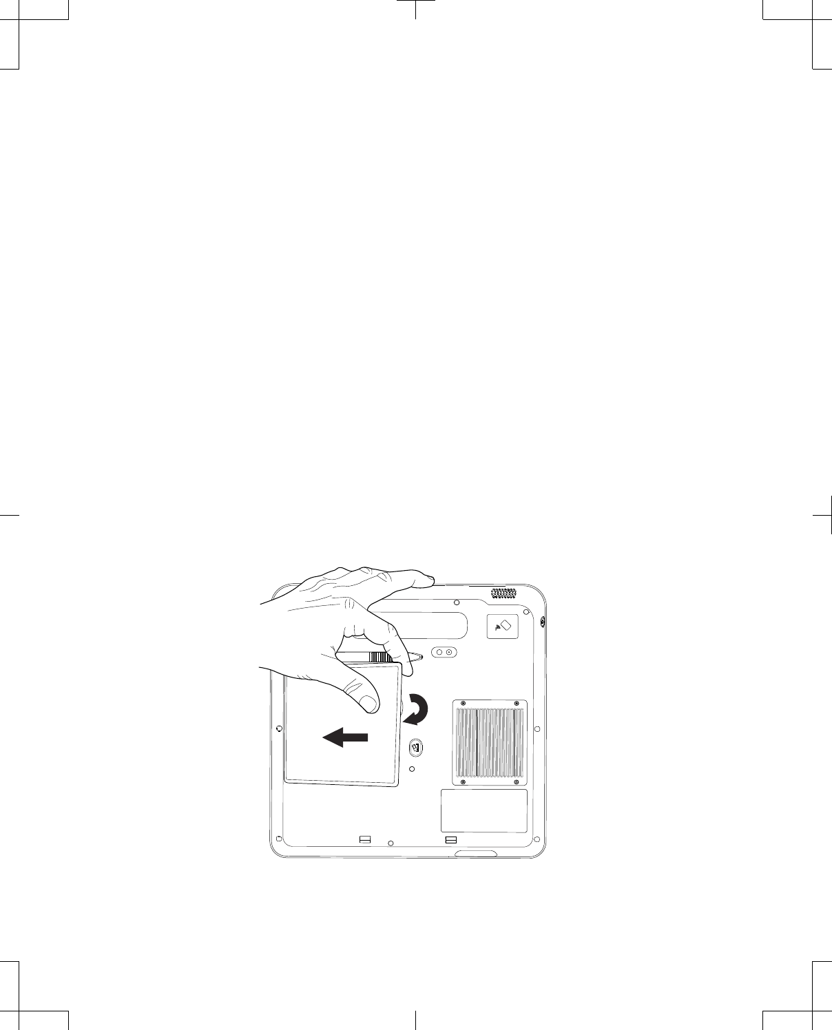
#Caution: To prevent damage to the programmer system components:
▪do not expose to excessive fluid,
▪do not immerse in liquid, and
▪do not drop.
If any of the programmer system components have been damaged, do not use.
Installing or removing the programmer battery
wWarning: Use only the rechargeable battery supplied by Medtronic with the Model 8880CW
Clinician Programmer. There is a potential danger of explosion if the wrong battery type is used,
which may result in damage to the device and injury to the user.
Notes:
▪The first time the programmer is used, the battery should be installed and mains electricity through
the power supply should be connected for at least 4 hours to charge the battery.
▪If the lithium-ion rechargeable battery becomes nonfunctional, dispose of it in accordance with local
laws and regulations or return it to Medtronic for disposal.
To install the rechargeable battery in the programmer:
1. Turn off the programmer.
2. Correctly orient the battery in relation to the slot on the back of the programmer.
3. Place the side of the battery without the black connection into the slot first (Figure 38).
4. Press the battery into the slot until you hear it click into place.
Figure 38. Installing the battery.
52 English 8880CW 2013-03
Filename Date Time
UC200xxxxxx EN
7 x 9 inches (178 mm x 229 mm)
Medtronic
Confidential
HardwareShortManual.xsl - HardwareShortTemplate.fm
Template version: 07-06-2012
M937825A001 Rev X 2013- 03
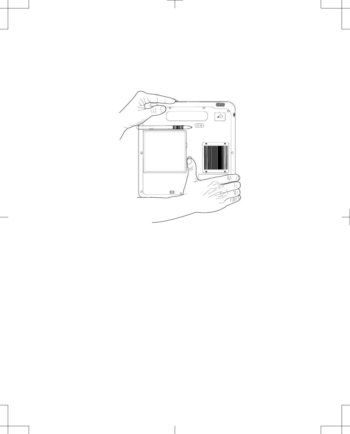
To remove the battery from the programmer:
1. Turn off the programmer.
2. Press the Battery Release button in until you hear a click indicating the battery has been released
(Figure 39).
3. Remove the battery from the programmer (Figure 40).
Figure 39. Battery Release button.
8880CW 2013-03 English 53
Filename Date Time
UC200xxxxxx EN
7 x 9 inches (178 mm x 229 mm)
Medtronic
Confidential
HardwareShortManual.xsl - HardwareShortTemplate.fm
Template version: 07-06-2012
M937825A001 Rev X 2013- 03
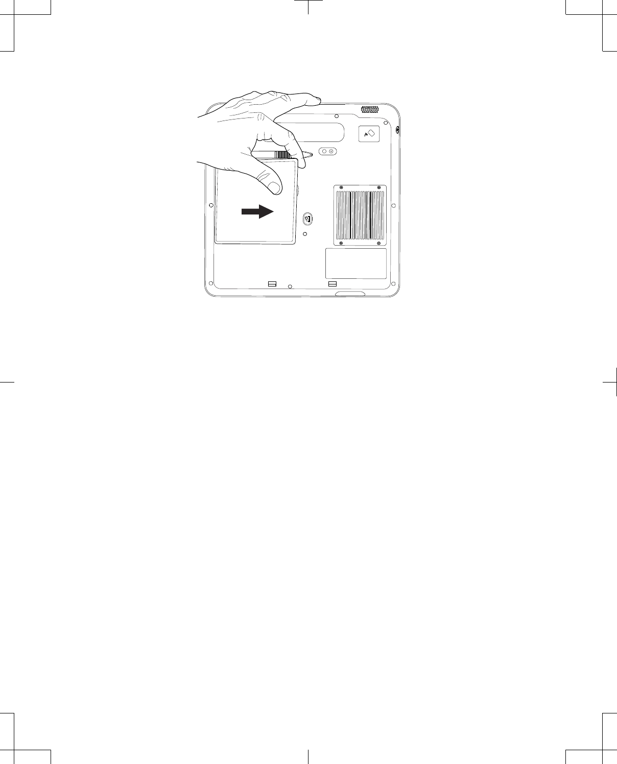
Figure 40. Removing the battery.
Charging the programmer battery
The rechargeable battery can be charged while it is installed in the programmer and mains electricity
through the power supply is connected, or by using the optional battery charger supplied by Medtronic.
A fully charged battery powers the programmer for 3.5 to 4.5 hours depending on the user settings. A
depleted battery requires 2.5 hours to fully charge.
Note: The first time the programmer is used, the battery should be installed and mains electricity
through the power supply should be connected for at least 4 hours to charge the battery.
wWarning: Use only the power supply and cord supplied by Medtronic. Do not use a portable
multiple-socket outlet or extension cord with the system. There is a potential danger of electric shock
or excessive heat if the wrong power supply, a portable multiple-socket outlet, or an extension cord
is used, which may result in damage to the device and injury to the user.
To use the battery charger:
1. Connect the DC end of the power supply to the power jack of the battery charger.
2. Place the battery into the charger so the connector on the battery aligns with the charger pins
(Figure 41).
An orange LED on the battery charger indicates the battery is charging. A green LED indicates the
battery is fully charged.
54 English 8880CW 2013-03
Filename Date Time
UC200xxxxxx EN
7 x 9 inches (178 mm x 229 mm)
Medtronic
Confidential
HardwareShortManual.xsl - HardwareShortTemplate.fm
Template version: 07-06-2012
M937825A001 Rev X 2013- 03
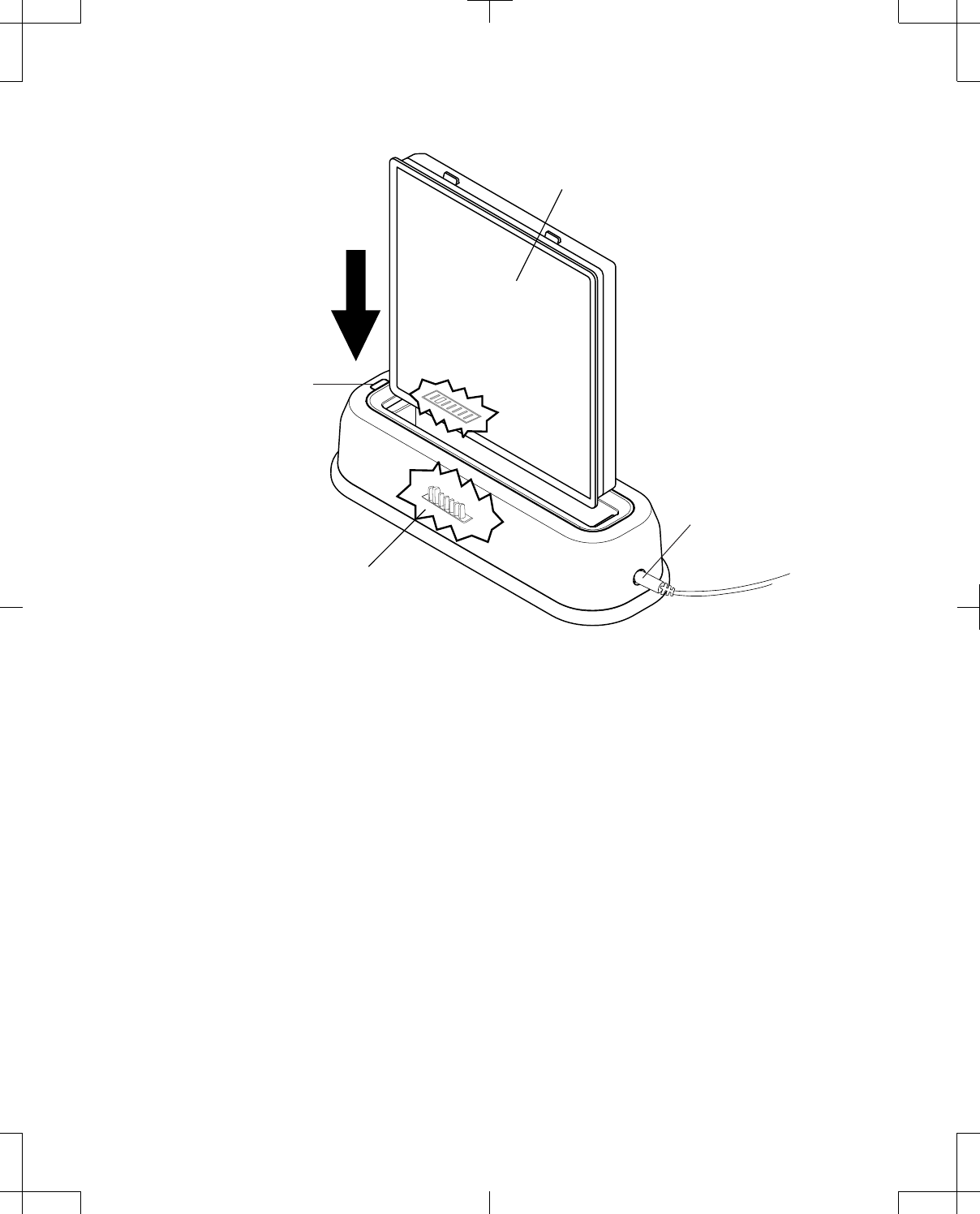
Battery
Charger pins
LED indicator
Power jack
Figure 41. Using the battery charger.
Changing the batteries in the telemetry head
#Caution: If the device will not be used for 2 weeks, remove the batteries from the device. A battery
left in the device may corrode, causing damage to the electronic components.
Notes:
▪Before inserting batteries, check for signs of battery leakage. If any residue is present, do not use.
▪Dispose of depleted batteries in accordance with local laws and regulations.
The Model 8880T2 Telemetry Head requires 2 AAA alkaline batteries.
To change the telemetry head batteries:
1. Release the battery compartment lid by sliding it downward (Figure 42).
2. Lift the battery compartment lid (Figure 43).
3. Remove depleted batteries.
4. Insert 2 new AAA alkaline batteries according to the orientation indicated on the inside of the battery
compartment.
8880CW 2013-03 English 55
Filename Date Time
UC200xxxxxx EN
7 x 9 inches (178 mm x 229 mm)
Medtronic
Confidential
HardwareShortManual.xsl - HardwareShortTemplate.fm
Template version: 07-06-2012
M937825A001 Rev X 2013- 03
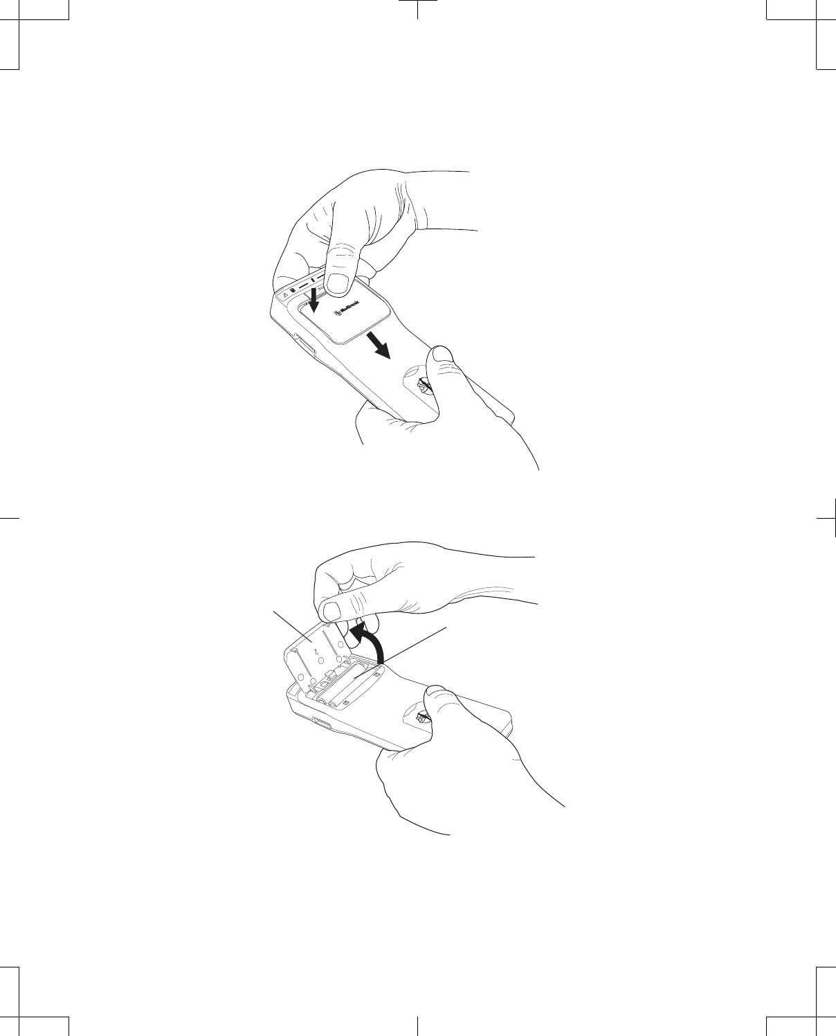
5. Close the battery compartment lid.
6. Secure the battery compartment lid by sliding it upwards.
Figure 42. Battery compartment lid.
Battery lid
Batteries
Figure 43. Battery compartment.
56 English 8880CW 2013-03
Filename Date Time
UC200xxxxxx EN
7 x 9 inches (178 mm x 229 mm)
Medtronic
Confidential
HardwareShortManual.xsl - HardwareShortTemplate.fm
Template version: 07-06-2012
M937825A001 Rev X 2013- 03

Calibrating the touchscreen
#Caution: Scratches on the touchscreen may interfere with selecting an option. If the touchscreen is
not responding appropriately, return the programmer to Medtronic for repair or replacement.
#Caution: If the touchscreen does not function as expected, the touchscreen may need to be
calibrated. Using the programmer while the touchscreen is out of calibration may result in
unintended programming or function selection.
Touchscreen calibration will increase the accuracy of the stylus pen.
To calibrate the programmer touchscreen:
1. Press the Control Menu button on the Control Panel.
2. Press the Utilities button in the Control Menu.
3. Press the Calibrate Display button in the Utilities window.
4. Press the stylus pen on the center of each target that is presented for 2 seconds.
5. Follow all instructions provided on the programmer screen.
To close the calibration function before it is compete, press the Cancel button.
Cleaning
When needed, clean the programmer and system components according to the following guidelines:
▪Always unplug the power supply from mains electricity before cleaning.
▪Keep liquid, including cleaning fluid, out of any openings.
▪Do not use spray cleaner directly on the products.
▪Do not use harsh or caustic chemical products. Use water or a mild cleanser.
▪Clean with a soft dry or lightly dampened cloth.
Troubleshooting
For assistance or for questions about the programmer and system components, contact the appropriate
representative listed on the inside back cover of this manual.
Clinician programmer error messages
Table 11. Clinician programmer error messages
Problem Possible Solution
Serious programmer error has occurred. Report the issue to Medtronic before restarting the
programmer.
8880CW 2013-03 English 57
Filename Date Time
UC200xxxxxx EN
7 x 9 inches (178 mm x 229 mm)
Medtronic
Confidential
HardwareShortManual.xsl - HardwareShortTemplate.fm
Template version: 07-06-2012
M937825A001 Rev X 2013- 03

Table 11. Clinician programmer error messages (continued)
Problem Possible Solution
The programmer has 10% or less of disk space
available.
Export and delete patient records in order to free disk
space. See "Moving patient records from one
programmer to another" on page 50 or "Removing
patient records from the programmer without exporting"
on page 51.
The programmer displays an empty blue screen. Restart the programmer. To restart the programmer,
press and hold the Power button for 8 seconds.
If the problem persists, contact Medtronic.
Network connection troubleshooting
Table 12. Network connection troubleshooting
Procedure Problem Possible Solution
Accessing a
network via
Ethernet:
The docking station is not powered. Check that the docking station is connected
to mains power through the power supply.
The LED indicator on the power supply and
the LED indicator on the front of the docking
station should be on.
The Ethernet cable is not connected. Check that the Ethernet cable is connected to
the docking station and to the wall jack. The
LED indicator within the Ethernet socket of
the docking station will flash if a connection is
made.
Network settings on the programmer may not
have been configured or may be incorrect.
Check the information in the Network
Settings tab of the Network window. (See
"Managing the programmer system" on
page 40.)
Note: Consult your IT department or network
documentation to determine the correct
settings for your location.
Accessing a WLAN: The wireless radio of the programmer is
disabled.
1. Disconnect the Ethernet cable.
2. To enable the wireless radio and connect
to a wireless network, see "Managing the
programmer system" on page 40.
Network settings on the programmer may not
have been configured or may be incorrect.
Check the information in the Wireless tab of
the Network window. (See "Managing the
programmer system" on page 40.)
Note: Consult your IT department or network
documentation to determine the correct
settings for your location.
Also check: There may be a problem with the network. Check that you are able to connect a clinic or
hospital computer to the network and that
network locations can be accessed from the
computer.
58 English 8880CW 2013-03
Filename Date Time
UC200xxxxxx EN
7 x 9 inches (178 mm x 229 mm)
Medtronic
Confidential
HardwareShortManual.xsl - HardwareShortTemplate.fm
Template version: 07-06-2012
M937825A001 Rev X 2013- 03

Printer connection troubleshooting
Table 13. Printer connection troubleshooting
Procedure Problem Possible Solution
Printing via a printer
USB cable:
The docking station is not powered. Check that the docking station is connected
to mains power through the power supply.
The LED indicator on the power supply and
the LED indicator on the front of the docking
station should be on.
The printer USB cable is not connected. Check that the printer USB cable is
connected to the USB port on the docking
station (or programmer if the programmer is
undocked).
There may be a problem with the docking
station.
Connect the printer USB cable to the USB
port on the programmer.
The printer driver may not be compatible with
the programmer.
Consult your printer manufacturer to
determine the correct page description
language, eg, PS (PostScript) or PCL (Printer
Command Language). Compatible printer
drivers are PCL3, PCL3e, PCL4, PCL5C
(color), PCL5e, PS2, PS2 (color), PS3.
Also check: You are trying to print to the wrong printer. Check that the correct default printer is
selected for use, see "Managing the
programmer system" on page 40.
There may be a problem with the printer. 1. Print a test page, "Managing the
programmer system" on page 40.
2. Contact the printer manufacturer for
printer-specific troubleshooting
information.
Resetting the Patient data security password
To reset the Patient data security password:
1. Open the Preferences window.
2. Press the Patient Data Security tab.
3. Press the Reset Password button.
4. Contact US Medtronic Technical Services at +1-800-328-0810 and provide the reset code displayed
in the Reset Password window.
5. Press the Medtronic password input box and use the keyboard to enter the password provided by
Medtronic.
6. Press the New password input box and use the keyboard to select characters.
7. Press the Confirm New Password input box and use the keyboard to select characters that match
the new password.
8. Press the OK button.
8880CW 2013-03 English 59
Filename Date Time
UC200xxxxxx EN
7 x 9 inches (178 mm x 229 mm)
Medtronic
Confidential
HardwareShortManual.xsl - HardwareShortTemplate.fm
Template version: 07-06-2012
M937825A001 Rev X 2013- 03

Safety and technical checks
Periodic safety checks are not required for the clinician programmer or system components.
Periodic maintenance of the programmer system is not required. The programmer system does not
contain serviceable components.
If a component of the programmer system requires repair or is nonfunctional, contact your Medtronic
representative listed on the inside back cover of this manual. For repair or disposal, send products to
the appropriate address.
USA and Asia-Pacific countries
Medtronic Neuromodulation
Repair Lab RCC135
Dock B
7000 Central Ave. N.E.
Minneapolis, MN 55432-3576
Europe, Africa, and Middle East countries
Medtronic EOC
Earl Bakkenstraat 10
Industry Park Trilandis
Heerlen, 6244PJ
The Netherlands
Canada
Medtronic Canada
6733 Kitimat Road
Mississauga, Ontario
Canada, L5N1W3
60 English 8880CW 2013-03
Filename Date Time
UC200xxxxxx EN
7 x 9 inches (178 mm x 229 mm)
Medtronic
Confidential
HardwareShortManual.xsl - HardwareShortTemplate.fm
Template version: 07-06-2012
M937825A001 Rev X 2013- 03

Contacts:
Asia: Medtronic International Ltd.
Tel. 02919-1362
Fax 02907-3998
Medtronic Asia Ltd.
Tel. (02)-548-1148
Fax (02)-518-4786
Australia: Medtronic Australasia Pty. Ltd.
97 Waterloo Road
North Ryde, NSW 2113
Australia
Tel. +61-2-9857-9000
Fax +61-2-9878-5100
Toll free 1-800-668-6700
Austria: Medtronic Österreich GmbH
Tel. 01-240440
Fax 01-24044-100
Belgium: Medtronic Belgium S.A.
Tel. 02-456-0900
Fax 02-460-2667
Canada: Medtronic of Canada Ltd.
Tel. (1-905)-460-3800
Fax (1905)-826-6620
Czech Republic: Medtronic Czechia s.r.o.
Tel. 2-965-795-80
Fax 2-965-795-89
Denmark: Medtronic Danmark A/S
Tel. 45-32-48-18-00
Fax 45-32-48-18-01
Finland: Medtronic Finland Oy/LTD
Tel. (09)-755-2500
Fax (09)-755-25018
France: Medtronic France S.A.S.
Tel. 01-5538-1700
Fax 01-5538-1800
Germany: Medtronic GmbH
Tel. (02159)-81490
Fax (02159)-8149100
Greece: Medtronic Hellas S.A.
Tel. 210-67-79-099
Fax 210-67-79-399
Hungary: Medtronic Hungária Kft.
Tel. 1-889-06-00
Fax 1-889-06-99
Ireland: Medtronic Ireland Ltd.
Tel. (01)-890-6522
Fax (01)-890-7220
Italy: Medtronic Italia SpA
Tel. 02-241371
Fax 02-241381
Tel. 06-328141
Fax 06-3215812
Japan: Medtronic Japan
Tel. 03-6430-2016
Fax 03-6430-7110
Latin America: Medtronic, Inc.
Tel. (1305)-500-9328
Fax (1786)-709-4244
Norway: Medtronic Norge AS
Tel. 067-10-32-00
Fax 067-10-32-10
Poland: Medtronic Poland Sp. z.o.o.
Tel. (022)-465-69-00
Fax (022)-465-69-17
Portugal: Medtronic Portugal, Lda.
Tel. 21-724-5100
Fax 21-724-5199
Russia: Medtronic Russia
Tel. (8495) 580-7377
Fax (8495) 580-7378
Slovakia Medtronic Slovakia, o.z.
Tel. 0268 206 911
Fax 0268 206 999
Spain: Medtronic Ibérica, S.A.
Tel. 91-625-0400
Fax 91-650-7410
Sweden: Medtronic AB
Tel. 08-568-585-00
Fax 08-568-585-01
Switzerland: Medtronic (Schweiz) AG
Tel. 031-868-0100
Fax 031-868-0199
The Netherlands: Medtronic B.V.
Tel. (045)-566-8000
Fax (045)-566-8668
U.K.: Medtronic U.K. Ltd.
Tel. 01923-212213
Fax 01923-241004
USA: Medtronic, Inc.
Tel. (1763)-505-5000
Fax (1763)-505-1000
Toll-free: (1-800)-328-0810
Filename Date Time
UC200xxxxxx EN
7 x 9 inches (178 mm x 229 mm)
Medtronic
Confidential
HardwareShortManual.xsl - HardwareShortTemplate.fm
Template version: 07-06-2012
M937825A001 Rev X 2013- 03
Manufacturer
Medtronic Inc.
710 Medtronic Parkway,
Minneapolis MN 55432-5604,
USA.
www.medtronic.com
Tel. +1-763-505-5000
Fax +1-763-505-1000
Authorized Representative
EC REP
in the European Community
Medtronic B.V.
Earl Bakkenstraat 10,
6422 PJ Heerlen,
The Netherlands
Tel. +31-45-566-8000
Fax +31-45-566-8668
Europe/Africa/Middle East
Headquarters
Medtronic International Trading Sàrl
Route du Molliau 31,
Case Postale 84
CH-1131 Tolochenaz,
Switzerland
www.medtronic.eu
Tel. +41-21-802-7000
Fax +41-21-802-7900
Asia-Pacific
Medtronic International Ltd.
Suite 1106-11, 11/F, Tower 1, The Gateway,
25 Canton Road, Tsimshatsui,
Kowloon,
Hong Kong
Tel. +852-2919-1362
Fax +852-2907-3998
Contacts for specific countries are listed inside this cover.
*M937825A001*© Medtronic, Inc. 2013
All Rights Reserved
M937825A001
Filename Date Time
UC200xxxxxx EN
7 x 9 inches (178 mm x 229 mm)
Medtronic
Confidential
HardwareShortManual.xsl - HardwareShortTemplate.fm
Template version: 07-06-2012
M937825A001 Rev X 2013- 03