Medtronic BLEIMPLANT Azure S SR MRI SureScan, Azure S DR MRI SureScan, Azure XT SR MRI SureScan, Azure XT DR MRI SureScan User Manual MAPS ID 502381 042

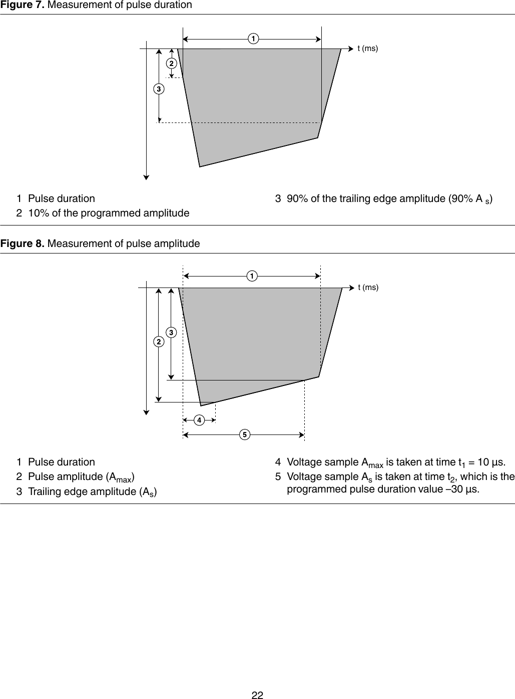
Medtronic, Inc. Azure S SR MRI SureScan, Azure S DR MRI SureScan, Azure XT SR MRI SureScan, Azure XT DR MRI SureScan MAPS ID 502381 042

User Manual

Azure™ S DR MRI SureScan™ W3DR01MR Conditional dual chamber pacemaker with SureScan™ technology and Bluetooth®wireless telemetry (OOE-DDDR)Device Manual
The following list includes trademarks or registered trademarks of Medtronic in the United States andpossibly in other countries. All other trademarks are the property of their respective owners.Azure, Capture Management, CareAlert, CareLink, Flashback, Medtronic, Medtronic CareAlert,Medtronic CareLink, MVP, Quick Look, SureScan, TherapyGuide
Contents1 System overview  41.1 CE mark of conformity  41.2 Introduction  41.3 System description  41.4 Indications and usage  51.5 Contraindications  51.6 MRI conditions for use  61.7 Feature summary  61.8 Data security  81.9 Pacing mode information  82 Warnings, precautions, and potential adverse events  92.1 General warnings and precautions  92.2 Explant and disposal  92.3 Handling and storage instructions  92.4 Lead evaluation and lead connection  102.5 Device operation  102.6 Potential adverse events  123 Implant procedure  133.1 Preparing for an implant  133.2 Selecting and implanting the leads  143.3 Testing the lead system  153.4 Connecting the leads to the device  163.5 Positioning and securing the device  173.6 Completing the implant procedure  183.7 Replacing a device  184 Product specifications  194.1 Physical characteristics  194.2 Electrical specifications  204.3 Replacement indicators  234.4 Projected service life  245 Device parameters  265.1 Emergency settings  265.2 Magnet application  265.3 Tachyarrhythmia detection parameters  265.4 Pacing parameters  275.5 Data collection parameters  315.6 Medtronic CareAlert parameters  325.7 System test parameters  335.8 EP study parameters  345.9 Nonprogrammable parameters  363
1  System overview1.1  CE mark of conformity20171.2  IntroductionThis manual describes the Medtronic Model W3DR01 Azure S DR MRI SureScan dual chamber, implantablepulse generator (IPG). It contains model-specific feature information, indications and contraindications, warningsand precautions, instructions for implanting the device, quick reference specifications, and parameter tables.Additional manuals and documents with information about the device:MRI technical manual – This manual provides MRI-specific procedures and warnings and precautions.Reference manual – This manual contains information about device features. The reference manual applies tomultiple models of IPG devices.Programming guide – This manual explains how to use the programmer software to conduct a patient session.Explanation of symbols – This document defines the symbols that may appear on the device package. Refer tothe package label to see which symbols apply specifically to this device.Medical Procedure and EMI Warnings and Precautions Manual for Health Care Professionals – Thismanual provides warnings, precautions, and guidance for health care professionals who perform medicaltherapies and diagnostic procedures on cardiac device patients. The manual also provides patient educationinformation related to sources of electromagnetic interference (EMI) at home, at work, and in other environments.Radio regulatory compliance information – This document provides compliance information related to theradio components of the device.1.3  System descriptionThe Medtronic Azure S DR MRI SureScan Model W3DR01 dual chamber implantable pulse generator (IPG) is amultiprogrammable cardiac device that monitors and regulates the patient’s heart rate by providing single or dualchamber rate-responsive bradycardia pacing. This device features Bluetooth wireless technology.1The MRI SureScan feature permits a mode of operation that allows a patient with a SureScan system to be safelyscanned by an MRI machine while the device continues to provide appropriate pacing. When programmed to On,MRI SureScan operation disables arrhythmia detection, magnet mode, and all user-defined diagnostics. Beforeperforming an MRI scan, refer to the MRI technical manual.Rate response – Rate response is controlled through an activity-based sensor.The users of this device include medical professionals (physicians, nurses, technicians, and their supporting staff)trained in surgery, cardiology, radiology, and magnetic resonance (MR) technology and able to implement theprocedures documented in the instructions for use for this device.1The Bluetooth® word mark is a registered trademark of Bluetooth SIG, Inc. and any use of this mark byMedtronic is under license.4
1.3.1  Usage environmentsThe device is intended to be used in the following environments and conditions:●The device will be implanted in a properly equipped, staffed, and sterile surgical environment. Implant will takeplace under standard surgical protocols and in the patient population for which the device is indicated.●Post-surgical patient and device follow-up care will take place in a properly equipped and staffed cardiologyclinic or office.●MRI procedures for patients with this device will take place in a properly equipped and staffed MR facility, andin consideration of the conditions and requirements described in Section 1.6, “MRI conditions for use”,page 6.●After having an implant, patients may resume their lives at home, at work, and in other environments withconsideration of the advice and restrictions documented in the Medical Procedure and EMI Warnings andPrecautions Manual for Health Care Professionals.1.3.2  System components and accessoriesContents of sterile package – The package contains 1 implantable pulse generator (IPG) and 1 torque wrench.Implantable device system – The Azure S DR MRI SureScan Model W3DR01 device and the pacing leadsconstitute the implantable portions of the device system.Leads – The lead system used with this device must provide sensing and pacing to the right ventricle (RV) and tothe atrium (A). Do not use any lead with this device without first verifying lead and connector compatibility.For information about selecting and implanting SureScan leads for this device, refer to Section 3.2, “Selecting andimplanting the leads”, page 14.Programmers and software – Medtronic programmers and software are used to program this device.Programmers from other manufacturers are not compatible with Medtronic devices, but they do not damageMedtronic devices.Medtronic pacing system analyzer – A pacing system analyzer is used to measure the electrical characteristicsof the implanted leads to assess their effectiveness for pacing and sensing.Medtronic patient monitor – Patients use the Medtronic patient monitor, if available, to gather information fromtheir implanted devices and communicate the information to their physicians through the Medtronic CareLinkNetwork. For information on using the patient monitor, refer to the patient monitor literature.1.4  Indications and usageThe Azure S DR MRI SureScan system is indicated for use in patients who may benefit from rate responsive ornon-rate responsive pacing to restore physiologic heart rates, improve cardiac output, prevent symptoms, orprotect against arrhythmias related to cardiac impulse formation or conduction disorders.1.5  ContraindicationsThe Medtronic Azure S DR MRI SureScan system is contraindicated for the following:●Concomitant implantation with another bradycardia device●Concomitant implantation with an implantable cardioverter defibrillator (ICD)●Rate responsive modes in patients who cannot tolerate pacing rates above the programmed lower rate●Dual chamber pacing in patients with chronic or persistent supraventricular tachycardias, including atrialfibrillation or flutter●Single chamber atrial pacing in patients with an AV conduction disturbance●Asynchronous pacing where spontaneous rhythms may cause competitive pacing5
1.6  MRI conditions for useA complete SureScan pacing system is required for use in the MR environment. A complete SureScanpacing system includes a SureScan device with Medtronic SureScan leads. Any other combination mayresult in a hazard to the patient during an MRI scan.Warning: Do not scan a patient without first programming the MRI SureScan mode to On. Scanning the patientwithout programming the MRI SureScan mode to On may result in patient harm or damage to the SureScan pacingsystem.Note: The MRI SureScan mode cannot be programmed to On if the device is recommended for replacement.Cardiology requirementsPatients and their implanted systems must be screened to meet the following requirements:●The patient has no implanted lead extenders, lead adaptors, or abandoned leads.●The patient has no broken leads or leads with intermittent electrical contact, as confirmed by lead impedancehistory.●The SureScan pacing system is implanted in the left or right pectoral region.●The pace polarity parameters are set to Bipolar for programming the MRI SureScan mode to On.●The SureScan device is operating within the projected service life.●For patients whose device will be programmed to an asynchronous pacing mode when the MRI SureScanmode is programmed to On, no diaphragmatic stimulation is present when the paced leads have a pacingoutput of 5.0 V and a pulse width of 1.0 ms.Caution: It is not recommended to perform an MRI scan if the right ventricular (RV) lead pacing capture thresholdis greater than 2.0 V at 0.4 ms for pacemaker-dependent patients. A higher pacing capture threshold may indicatean issue with the implanted lead.Notes:●For radiology requirements, refer to the MRI technical manual.●Before performing an MRI scan, refer to the MRI technical manual for MRI-specific warnings andprecautions.Patient monitoring and rescue requirements●Continuous patient monitoring is required during the MRI scan.●In the event that patient rescue is required, an external defibrillator must be immediately available.1.7  Feature summaryThe following features are available in this device. For a list of the features that are enabled at shipping, see the“Shipped” column of the tables in Chapter 5, “Device parameters”, page 26.1.7.1  Pacing featuresAtrial Capture Management – This feature monitors the atrial pacing threshold with daily pacing thresholdsearches and, if programmed to do so, adjusts the atrial pacing amplitude toward a target amplitude.Atrial Preference Pacing (APP) – The system provides an overdrive pacing technique designed to counteractpotential atrial tachyarrhythmia initiating mechanisms. APP maintains a consistent activation sequence byproviding continuous pacing that is slightly higher than the intrinsic rate.Auto-adjusting sensitivity – This feature automatically adjusts the sensitivity thresholds after specific pacedevents and sensed events occur.Automatic polarity configuration – This device uses lead impedance measurements to automatically configurepacing and sensing polarities during Implant Detection.6
Automatic PVARP – This feature adjusts PVARP (Post-Ventricular Atrial Refractory Period) in response tochanges in the patient’s heart rate or pacing rate. PVARP is longer at lower tracking rates to preventpacemaker-mediated tachycardia (PMT) and shorter at higher rates to maintain 1:1 tracking.Mode Switch – This feature switches the device from a tracking mode to a nontracking mode to prevent rapidventricular pacing that may result from a high atrial rate, and restores the programmed pacing mode when the atrialtachyarrhythmia ends.MRI SureScan – This feature allows patients with an implanted MRI SureScan system, including the device andleads, to have a safe MRI procedure if the requirements provided in the MRI technical manual are followed.MVP (Managed Ventricular Pacing) – The MVP feature promotes intrinsic conduction by reducing unnecessaryright ventricular pacing. This feature operates when the programmed mode is either AAIR<=>DDDR orAAI<=>DDD.Non-Competitive Atrial Pacing (NCAP) – This feature prevents pacing the atrium too soon after a refractoryatrial sense by delaying the scheduled atrial pace.Pacemaker-mediated Tachycardia (PMT) Intervention – This feature provides automatic detection andinterruption of device-defined PMTs.PVC Response – This feature extends PVARP following a premature ventricular contraction (PVC) to avoidtracking a retrograde P-wave and to prevent retrograde conduction from inhibiting an atrial pace.Rate Adaptive AV (RAAV) – This feature varies the Paced AV (PAV) and Sensed AV (SAV) intervals as the heartrate increases or decreases during dual chamber operation to maintain 1:1 tracking and AV synchrony.Rate Drop Response – This feature monitors the heart for a significant drop in rate and responds by pacing theheart at an elevated rate for a programmed duration.Rate Profile Optimization – The goal of Rate Profile Optimization is to ensure that the rate response remainsappropriate for the full range of patient activities. This feature monitors the patient’s daily and monthly sensor rateprofiles and adjusts the rate response curves over time to achieve a prescribed target rate profile.Rate-responsive pacing – This feature varies the pacing rate in response to the patient’s physical motion asdetected by the activity sensor of the device.RV Capture Management – This feature monitors the right ventricular pacing threshold with daily pacingthreshold searches and, if programmed to do so, adjusts the RV pacing amplitude toward a target amplitude.Sleep feature – This feature causes the device to pace at a slower rate during a programmed sleep period.Ventricular Safety Pacing (VSP) – This feature prevents inappropriate inhibition of ventricular pacing caused bycrosstalk or ventricular oversensing.1.7.2  Monitoring and follow-up featuresMedtronic CareAlert Monitoring – If the device identifies any programmed or automatic CareAlert conditions,this feature sends a wireless alert signal to the patient monitor (if available). The patient monitor then transmits theCareAlert Event data to the Medtronic CareLink Network. If configured to do so, the Medtronic CareLink Networkthen sends an alert notification to the clinic.Episode data and EGM storage – The system provides an arrhythmia episode log that enables you to view thesummary and detailed diagnostic data quickly, including stored EGM, for the selected arrhythmia episode.Flashback memory – This diagnostic feature records intervals that occur immediately prior to tachyarrhythmiaepisodes or the most recent interrogation and plots the interval data over time.Holter telemetry – This function allows the implanted device to transmit an EGM with marker telemetrycontinuously for up to 46 hours, regardless of the use of the programming head.Implant Detection – Implant Detection is a 30 min period, beginning when the device is placed in the surgicalpocket. During this period, the device verifies lead connection by measuring lead impedance. When the ImplantDetection period is completed, various automatic features and diagnostics are activated.7
Lead Monitor – This feature measures lead impedances during the life of the implanted device and controlsautomatic configuration of lead polarities at implant. If Lead Monitor is programmed to Adaptive, the deviceautomatically switches bipolar pacing and sensing to unipolar pacing and sensing if the integrity of a bipolar leadis compromised.MVP Mode Switches – This feature lists the 10 most recent MVP Mode Switches to DDD(R).Rate Histograms report – This report shows heart rate range distributions for the patient.TherapyGuide – This feature provides a set of suggested parameters based on the programmed informationabout the patient’s clinical conditions. The TherapyGuide feature does not replace a physician’s expert judgment.The physician is free to accept, reject, or modify any of the suggested parameter values.1.8  Data securityMedtronic has designed safeguards to protect patient information and device data for theAzure S DR MRI SureScan Model W3DR01 device.Bluetooth communication system – The device shows its availability through Bluetooth communication.Critical data accepted or sent through the Bluetooth communication from the device is encrypted by the devicebefore it is sent over the Bluetooth channel. The device responds only to authorized commands.Inductive telemetry communication system – The Medtronic inductive telemetry communication system isused with the clinician programmer to interrogate and program the device. It can also be used to interrogate thedevice for remote monitoring, if available. This system uses short-range communication that protects patientinformation and device data.1.9  Pacing mode informationPacemaker modes are described using the NBG code. The five-letter NBG code, named after The North AmericanSociety of Pacing and Electrophysiology (NASPE) and the British Pacing and Electrophysiology Group (BPEG),describes the operation of implantable pulse generators. The NBG code, which supersedes the ICHD Code, isdescribed in Table 1.Table 1. The Revised NASPE/BPEG Generic Code for antibradycardia pacingPosition: I II III IV VCategory: Chamber(s)PacedChamber(s)SensedResponse toSensingRate Modula-tionMultisite Pac-ingaO = NoneA = AtriumV = VentricleD = Dual(A + V)O = NoneA = AtriumV = VentricleD = Dual(A + V)O = NoneT = TriggeredI = InhibitedD = Dual(T + I)O = NoneR = Rate mod-ulationO = NoneA = AtriumV = VentricleD = Dual(A + V)Manufacturers’designationonly:S = Singleb(A or V)S = Singleb(A or V)aMedtronic devices do not use the Multisite Pacing code.bThe programmer displays A or V (not S) for chambers paced and sensed.8
2  Warnings, precautions, and potential adverse events2.1  General warnings and precautionsBefore performing an MRI scan, refer to the Medtronic MRI technical manual for MRI-specific warningsand precautions.Refer to the Medical Procedure and EMI Warnings and Precautions Manual for information about hazards relatedto medical therapies and diagnostic procedures on patients with cardiac devices. This manual also includesinformation about sources of EMI in the patient’s environment.Anti-coagulation – Use of the device should not change the application of established anti-coagulation protocols.Electrical isolation during implant – Do not allow the patient to have contact with grounded electrical equipmentthat might produce electrical current leakage during implant. Electrical current leakage may inducetachyarrhythmias that may result in the patient’s death.External defibrillation equipment – Keep external defibrillation equipment nearby for immediate use whenevertachyarrhythmias are possible or intentionally induced during device testing, implant procedures, or post-implanttesting.Lead compatibility – Do not use another manufacturer’s leads without demonstrated compatibility withMedtronic devices. If a lead is not compatible with a Medtronic device, the result may be undersensing of cardiacactivity, failure to deliver necessary therapy, or a leaking or intermittent electrical connection.A complete SureScan pacing system includes a SureScan device connected to SureScan leads. Beforeperforming an MRI scan, refer to the Medtronic MRI technical manual for additional information.2.2  Explant and disposalConsider the following information related to device explant and disposal:●Explant the implantable device postmortem. In some countries, explanting battery-operated implantabledevices is mandatory because of environmental concerns; please check the local regulations. In addition, ifsubjected to incineration or cremation temperatures, the device may explode.●Medtronic implantable devices are intended for single use only. Do not resterilize and reimplant explanteddevices.●Contact Medtronic for Return Mailer Kits to return explanted devices for analysis and disposal. See the backcover for addresses.2.3  Handling and storage instructionsCarefully observe these guidelines when handling or storing the device.2.3.1  Device handlingChecking and opening the package – Before opening the sterile package tray, visually check for any signs ofdamage that might invalidate the sterility of the package contents.If the package is damaged – The device packaging consists of an outer tray and an inner tray. Do not use thedevice or accessories if the outer or inner packaging tray is wet, punctured, opened, or damaged. Return thedevice to Medtronic because the integrity of the sterile packaging or the device functionality may be compromised.This device is not intended to be resterilized.If the package information is damaged – If any information on the outer package or the sterile package isdefaced or damaged so that you cannot read it, notify Medtronic so that the device can be replaced.If the printed manual is illegible – If this manual is supplied in its printed form and any part of it is illegible, contactMedtronic to request a replacement manual.Sterilization – Medtronic has sterilized the package contents with ethylene oxide before shipment. This device isfor single use only and is not intended to be resterilized.9
Device temperature – Allow the device to reach room temperature before it is programmed or implanted. Devicetemperature above or below room temperature may affect initial device function.Dropped device – Do not implant the device if it is dropped on a hard surface from a height of 30 cm or more afterit is removed from its packaging.Fluid immersion – Do not immerse the device in fluid or flush the connector ports at the time of implant. Doing socould adversely affect the performance of the device and lead system.“Use by” date – Do not implant the device after the “Use by” date because the battery longevity could be reduced.For single use only – Do not resterilize and reimplant an explanted device.2.3.2  Device storageAvoid magnets – To avoid damaging the device, store the device in a clean area away from magnets, kitscontaining magnets, and any sources of electromagnetic interference.Temperature limits – Store and transport the package between –18°C and +55°C. Device reset may occur attemperatures below –18°C. Device longevity may decrease and performance may be affected at temperaturesabove +55°C.2.4  Lead evaluation and lead connectionRefer to the lead technical manuals for specific instructions and precautions about lead handling.A Medtronic MRI SureScan system includes a Medtronic MRI SureScan device connected to Medtronic MRISureScan leads. Before performing an MRI procedure, refer to the Medtronic MRI technical manual foradditional information.Torque wrench – Use only the torque wrench supplied with the device. The torque wrench is designed to preventdamage to the device from overtightening a setscrew. Other torque wrenches (for example, a blue-handled orright-angled hex wrench) have torque capabilities greater than the lead connector can tolerate.Lead connection – Consider the following information when connecting the lead and the device:●Cap abandoned leads to avoid transmitting electrical signals.●Plug any unused lead ports to protect the device.●Verify lead connections. Loose lead connections may result in inappropriate sensing and failure to deliverarrhythmia therapy.2.5  Device operationLeads – Bipolar or unipolar leads may be used with the Azure S DR MRI SureScan Model W3DR01 device, butif leads other than bipolar MRI SureScan leads are used, the system is contraindicated for MRI scans.Accessories – Use this device only with accessories, parts subject to wear, and disposable items that have beentested to technical standards and found safe by an approved testing agency.Maximum output for the Atrial Capture Management feature – The Atrial Capture Management feature doesnot adjust atrial outputs to values greater than 5.0 V or 1.0 ms. If the patient needs atrial pacing output greater than5.0 V or 1.0 ms, manually program the atrial amplitude and pulse width. If a lead dislodges partially or completely,the Atrial Capture Management feature may not prevent loss of capture.Device status indicators – If any of the device status indicators (for example, Device Reset) are displayed on theprogrammer after interrogating the device, inform a Medtronic representative immediately. If these device statusindicators are displayed, therapies may not be available to the patient.Effects of myopotential sensing in unipolar sensing configurations – In unipolar sensing configurations, thedevice may not distinguish myopotentials from cardiac signals. This may result in a loss of pacing due to inhibition.Also, unipolar atrial sensing in atrial tracking modes can result in elevated ventricular pacing rates. To addressthese situations, the device may be programmed to be less sensitive (using higher sensitivity values). However,the sensitivity level must be balanced against the potential to undersense true cardiac signals. Typically, this10
balance is easily attained for ventricular sensing using sensitivity values around 2.8 mV, but it may be difficult toattain for atrial sensing because of the smaller P-wave amplitudes.Device reset – Device reset can be caused by exposure to temperatures below –18°C or strong electromagneticfields. Advise patients to avoid strong electromagnetic fields. Observe temperature storage limits to avoidexposure of the device to cold temperatures. If a partial reset occurs, pacing resumes in the programmed modewith many of the programmed settings retained. If a full reset occurs, the device operates in VVI mode at 65 min–1.Device reset is indicated by a programmer warning message that is displayed immediately upon interrogation. Torestore the device to its previous operation, it must be reprogrammed. Inform a Medtronic representative if yourpatient’s device has reset.End of Service (EOS) indicator – Replace the device immediately if the programmer displays an EOS indicator.The device may soon lose the ability to pace, sense, and deliver therapy adequately.Extended Upper Tracking Rate – When programming Upper Tracking Rates of 190, 200, or 210 min–1, be carefulto ensure that these rates are appropriate for the patient.False bipolar pathway with unipolar lead – When implanting a unipolar lead, ensure that the tip setscrew isproperly engaged and that all electrical contacts are sealed to prevent electrical leakage. Electrical leakage maycause the device to inappropriately identify a unipolar lead as bipolar, resulting in loss of output.Magnets – Placing a magnet over the device suspends tachyarrhythmia detection and initiates asynchronous,fixed-rate bradycardia pacing. The programming head contains a magnet that can cause magnet operation tooccur. However, magnet operation does not occur if telemetry between the device and the programmer isestablished or if the MRI SureScan mode is programmed to On.Pace polarity – Pace polarity must be bipolar to program the MRI SureScan mode to On.Pacemaker-mediated tachycardia (PMT) intervention – Even with the PMT Intervention feature programmedto On, PMTs may still require clinical intervention, such as device reprogramming, drug therapy, or lead evaluation.Pacing and sensing safety margins – Lead maturation (at least one month after implant) may cause sensingamplitudes to decrease and pacing thresholds to increase, which can cause undersensing or a loss of capture.Provide an adequate safety margin when selecting values for pacing amplitude, pacing pulse width, and sensitivityparameters.Programmers – Use only Medtronic programmers and application software to communicate with the device.Programmers and software from other manufacturers are not compatible with Medtronic devices.Rate control – Decisions regarding rate control should not be based on the ability of the device to prevent atrialarrhythmias.Rate-responsive modes – Do not program rate-responsive modes for patients who cannot tolerate rates abovethe programmed Lower Rate. Rate-responsive modes may cause discomfort for those patients.Right ventricular apical pacing – Right ventricular apical pacing may be associated with an increased risk ofatrial fibrillation, left ventricular dysfunction, and congestive heart failure.Maximum output for the RV Capture Management feature – The RV Capture Management feature does notprogram right ventricular outputs to values greater than 5.0 V or 1.0 ms. If the patient needs right ventricular pacingoutput greater than 5.0 V or 1.0 ms, manually program right ventricular amplitude and pulse width. If a leaddislodges partially or completely, the RV Capture Management feature may not prevent loss of capture.Sensitivity setting – Carefully evaluate the possibility of increased susceptibility to EMI and oversensing beforechanging the sensitivity from its nominal setting to a more sensitive setting.Shipping values – Do not use shipping values or nominal values for pacing amplitude and sensitivity withoutverifying that the values provide adequate safety margins for the patient.Single chamber atrial modes – Do not program single chamber atrial modes for patients with impaired AV nodalconduction. Ventricular pacing does not occur in these modes.11
Slow retrograde conduction and PMT – Slow retrograde conduction may induce pacemaker-mediatedtachycardia (PMT) when the VA conduction time is greater than 400 ms. Programming PMT Intervention can helpprevent PMT only when the VA conduction time is less than 400 ms.2.5.1  Pacemaker-dependent patientsVentricular Safety Pacing – Always program Ventricular Safety Pacing (VSP) to On for pacemaker-dependentpatients. Ventricular Safety Pacing prevents ventricular asystole due to inappropriate inhibition of ventricularpacing caused by oversensing in the ventricle.ODO pacing mode – Pacing is disabled under the ODO pacing mode. Do not program the ODO mode forpacemaker-dependent patients. Instead, use the Underlying Rhythm Test to provide a brief period without pacingsupport.Polarity override – Do not override the polarity verification prompt with bipolar polarity when a unipolar lead isconnected. Overriding the polarity verification prompt results in no pacing output.Underlying Rhythm Test – Use caution when using the Underlying Rhythm Test to inhibit pacing. The patient iswithout pacing support when pacing is inhibited.2.6  Potential adverse eventsPotential adverse events associated with the use of a device system (defined as the device and leads) include, butare not limited to, the following:●Air embolism●Allergic reaction●Bleeding●Body rejection phenomena including local tissue rejection●Cardiac dissection●Cardiac perforation●Cardiac tamponade●Chronic nerve damage●Death●Embolism●Endocarditis●Erosion of the device and lead through the skin●Excessive fibrosis●Extrusion●Fibrillation or other arrhythmias●Fluid accumulation●Formation of cysts●Heart block●Heart wall rupture●Hematoma/seroma●Inappropriate acceleration of arrhythmias●Infection●Keloid formation●Lead abrasion and discontinuity●Lead migration/dislodgment●Muscle and nerve stimulation●Myocardial damage●Myocardial irritability●Myopotential sensing●Pericardial effusion●Pericardial rub●Pneumothorax●Threshold elevation12
●Thromboemboli●Thrombosis●Transvenous lead-related thrombosis●Valve damage (particularly in fragile hearts)●Venous occlusion●Venous perforation●Vein wall rupture3  Implant procedure3.1  Preparing for an implantThe following implant procedures are provided for reference only. Proper surgical procedures and steriletechniques are the responsibility of the physician. Each physician must apply the information in these proceduresaccording to professional medical training and experience.For information about replacing a previously implanted device, see Section 3.7, “Replacing a device”, page 18.Ensure that you have all of the necessary instruments, system components, and sterile accessories to perform theimplant.Connect the skin electrodes to the patient if you would like to display surface ECG signals on the programmer. Seethe programmer reference manual for more information.3.1.1  Instruments, components, and accessories required for an implantThe following non-implanted instruments are used to support the implant procedure:●Medtronic programmer with a programming head●programmer software application for the Azure S DR MRI SureScan Model W3DR01 device●Model 2290 Analyzer or equivalent pacing system analyzer●external defibrillatorThe following sterile system components and accessories are used to perform the implant:●implantable device and lead system components●programming head sleeveNote: If a sterilized programming head is used during an implant, a sterile programming head sleeve is notnecessary.●pacing system analyzer cables●lead introducers appropriate for the lead system●extra stylets of appropriate length and shape3.1.2  Setting up the programmer and starting the applicationSee the programmer reference manual for instructions about how to set up the programmer. The softwareapplication for the Azure S DR MRI SureScan Model W3DR01 device should be installed on the programmer. YourMedtronic representative can install this software, if necessary. Establish telemetry with the device and start apatient session.13
3.1.3  Considerations for preparing for an implantReview the following information before implanting the leads or device:Before performing an MRI scan, refer to the Medtronic MRI Technical Manual for additional information.Warning: Bipolar or unipolar leads may be used with the Azure S DR MRI SureScan Model W3DR01 device, butif leads other than bipolar SureScan leads are used, the system is not approved for MRI scans. Before performingan MRI scan, refer to the Medtronic MRI technical manual for additional information.Warning: Do not allow the patient to have contact with grounded electrical equipment that might produce electricalcurrent leakage during implant. Electrical current leakage may induce tachyarrhythmias that may result in thepatient’s death.Warning: Keep external defibrillation equipment nearby for immediate use. Potentially harmful spontaneous orinduced tachyarrhythmias may occur during device testing, implant procedures, and post-implant testing.Caution: The device is intended for implant in the pectoral region with Medtronic transvenous leads. No claims ofsafety and efficacy can be made with regard to other acutely or chronically implanted lead systems that are notmanufactured by Medtronic.Caution: Unipolar atrial leads may be used with the device, but bipolar atrial leads are recommended. If unipolaratrial leads are used, the Capture Management feature must be programmed to Off.Caution: Do not implant the device after the “Use by” date on the package label. Battery longevity may be reduced.To retain the ability to safely scan the SureScan pacing system during MRI scans, the MRI conditions for use inSection 1.6, “MRI conditions for use”, page 6 must be followed. Refer to the MRI technical manual for additionalinformation.3.1.4  How to prepare the device for implantBefore opening the sterile package, perform the following steps to prepare the device for implant:1. Interrogate the device and print an Initial Interrogation Report.Caution: If the programmer reports that a device reset occurred, do not implant the device. Contact aMedtronic representative.2. Check the Initial Interrogation Report to confirm that the battery voltage is at least 2.85 V at room temperature.If the device has been exposed to low temperatures, then the battery voltage will be temporarily lower. Allowthe device to warm to room temperature for at least 48 hours and check the battery voltage again. If anacceptable battery voltage cannot be obtained, contact a Medtronic representative.Note: The device automatically measures the battery voltage several times a day. The battery voltagereported on the Battery and Lead Measurements screen is an average of recent automatic measurementvalues.3. Select Params > Data Collection Setup > Device Date/Time… to select the Time Zone for the internal clockof the device.4. Program the therapy and pacing parameters to values appropriate for the patient.Note: Do not enable a pacing feature that affects the pacing rate before implanting the device. Doing so mayresult in a pacing rate that is faster than expected.3.2  Selecting and implanting the leadsUse the guidelines in this section to select leads that are compatible with the device. The appropriate techniquesfor implanting the leads may vary according to physician preference and the patient’s anatomy or physicalcondition. Consult the technical manuals supplied with the leads for specific implant instructions.14
A complete SureScan pacing system is required for use in the MR environment. A complete SureScanpacing system includes a SureScan device with Medtronic SureScan leads. Any other combination mayresult in a hazard to the patient during an MRI scan.3.2.1  Selecting the leadsThe device is typically implanted with the following leads:●1 bipolar transvenous lead in the right ventricle (RV) for sensing and pacing●1 bipolar transvenous lead in the atrium (A) for sensing and pacing. Use of a bipolar atrial lead with ring andtip electrodes spaced ≤ 10 mm apart to reduce far-field R-wave sensing is recommended.3.2.2  How to verify lead and connector compatibilityWarning: Verify lead and connector compatibility before using a lead with this device. Using an incompatible leadmay damage the connector, resulting in electrical current leakage or resulting in an intermittent electricalconnection.Note: Medtronic 3.2 mm low-profile leads are not directly compatible with the device IS-1 connector block.Note: Lead adaptors compromise the ability to safely scan the SureScan pacing system during an MRI scan.Patients with lead adaptors are contraindicated for an MRI scan.Use the information in Table 2 to select a compatible lead.Table 2. Lead and connector compatibilityConnector port Primary leadsA, V IS-1a bipolar and IS-1 unipolaraIS-1 refers to the international standard ISO 5841-3.3.2.3  Implanting the leadsImplant the leads according to the instructions in the technical manuals supplied with the leads unless suitablechronic leads are already in place.Warning: Pinching the lead can damage the lead conductor or insulation, which may result in the loss of sensingor pacing therapy.Transvenous leads – If you use a subclavian approach to implant a transvenous lead, position the lead laterallyto avoid pinching the lead body between the clavicle and the first rib.3.3  Testing the lead systemAfter the leads are implanted, test the lead system to verify that the sensing and pacing values are acceptable.Refer to the literature provided with the pacing system analyzer for instructions.Note: Do not measure the intracardiac EGM telemetered from the device to assess sensing.Note: The measured pacing lead impedance is a reflection of measuring equipment and lead technology. Referto the lead technical manual for acceptable impedance values.Bipolar leads – When measuring sensing and pacing values, measure between the tip (cathode) and ring(anode) of each bipolar pacing/sensing lead.Unipolar leads – When measuring sensing and pacing values, measure between the tip (cathode) of eachunipolar pacing/sensing lead and an indifferent electrode (anode) used in place of the device can.15
Table 3. Acceptable sensing and pacing valuesMeasurements required Acute transvenous leads Chronic leadsaP-wave EGM amplitude (atrial) ≥ 2 mV ≥ 1 mVR-wave EGM amplitude (RV) ≥ 5 mV ≥ 3 mVSlew rate≥ 0.5 V/s (atrial) ≥ 0.3 V/s (atrial)≥ 0.75 V/s (RV) ≥ 0.5 V/s (RV)Capture threshold (0.5 ms pulse width)≤ 1.5 V (atrial) ≤ 3.0 V (atrial)≤ 1.0 V (RV) ≤ 3.0 V (RV)aChronic leads are leads implanted for 30 days or more.3.4  Connecting the leads to the deviceThe following procedure describes how to connect a lead to the device, confirm that the lead connector is fullyinserted in the connector block, and verify that the lead connection is secure.Warning: After connecting the leads, verify that the lead connections are secure by gently tugging on each lead.A loose lead connection may result in inappropriate sensing, which can cause false tracking and false inhibition ofpacing.Caution: Use only the torque wrench supplied with the device. The torque wrench is designed to prevent damageto the device from overtightening a setscrew.3.4.1  How to connect a lead to the device1. Insert the torque wrench into the appropriate setscrew.a. If the setscrew obstructs the port, retract the setscrew by turning it counterclockwise until the port is clear.Take care not to disengage the setscrew from the connector block (see Figure 1).b. Leave the torque wrench in the setscrew until the lead connection is secure. This action allows a pathwayfor venting trapped air when the lead connector is inserted into the connector port.Figure 1. Inserting the torque wrench into the setscrew1a 1b 2. Push the lead connector into the connector port until the lead connector pin is clearly visible in the pin viewingarea. No sealant is required.16
3. Confirm that the lead is fully inserted into the connector pin cavity by viewing the device connector block fromthe side or end.a. The lead connector pin should be clearly visible beyond the setscrew block (see Figure 2).b. The lead connector ring should be completely inside the spring contact block. There is no setscrew in thislocation (see Figure 2).Figure 2. Confirming the lead connection3b3a 4. Tighten the setscrew by rotating it clockwise until the torque wrench clicks. Remove the torque wrench.5. Gently tug on the lead to confirm a secure fit. Do not pull on the lead until the setscrew has been tightened.6. Repeat these steps for each lead.3.5  Positioning and securing the deviceNote: Implant the device within 4 cm of the surface of the skin to optimize post-implant ambulatory monitoring.3.5.1  How to position and secure the device1. Verify that each lead connector pin is fully inserted into the connector port and that all setscrews are tight.2. To prevent twisting of the lead body, rotate the device to loosely wrap the excess lead length (see Figure 3).Do not kink the lead body.Figure 3. Rotating the device to wrap the leads 3. Place the device and the leads into the surgical pocket.4. Use nonabsorbable sutures to secure the device within the pocket and minimize post-implant rotation andmigration. Use a surgical needle to penetrate the suture hole on the device.5. Suture the pocket incision closed.17
3.6  Completing the implant procedure3.6.1  How to complete programming the device1. If unipolar leads are implanted, you may want to manually complete the Implant Detection process.a. Select the Params icon.b. Program the Pace Polarity and Sense Polarity parameters to Unipolar.c. Select Additional Features… and program the Implant Detection parameter to Off/Complete.2. Verify that the pacing and detection parameters are programmed to values that are appropriate for the patient.3. Enter the patient’s information.Note: Be sure to use the Patient Information screen to enter complete information about the implanted leads.Be sure to use the MRI SureScan System/Other Hardware screen to enter complete information about otherhardware implanted in the patient, including abandoned devices or leads, and lead extenders or adaptors.This information will be used in the future if the patient needs to be evaluated for an MRI scan. For moreinformation, see the programming guide.4. Program the Medtronic CareAlert parameters, if applicable.5. Program the Data Collection Setup parameters.3.6.2  How to assess the performance of the device and leadsAfter implanting the device, x-ray the patient as soon as possible to verify device and lead placement. Before thepatient is discharged from the hospital, assess the performance of the implanted device and leads.1. Monitor the patient’s electrocardiogram until the patient is discharged. If a lead dislodges, it usually occursduring the immediate postoperative period.2. Check the pacing and sensing values, and adjust the values if necessary. Verify the safety margin for thepacing threshold.3. Interrogate the device, and print a Final Report to document the postoperative programmed device status.3.7  Replacing a deviceTo retain the ability to safely scan the SureScan pacing system during MRI scans, the MRI conditions for use inSection 1.6, “MRI conditions for use”, page 6 must be followed. Refer to the Medtronic MRI technical manual foradditional information.Warning: Bipolar or unipolar leads may be used with the Azure S DR MRI SureScan Model W3DR01 device, butif leads other than bipolar SureScan leads are used, the system is not approved for MRI scans. Before performingan MRI scan, refer to the Medtronic MRI technical manual for additional information.Warning: Abandoned leads or previously implanted non-MRI labeled leads compromise the ability to safely scanthe SureScan pacing system during future MRI scans. When implanting a SureScan pacing system, consider therisks associated with removing previously implanted leads before removing the leads to maintain the ability tosafely scan the SureScan pacing system. Refer to the Medtronic MRI technical manual for additional information.Warning: Keep external pacing equipment nearby for immediate use. The patient does not receive pacing therapyfrom the device when the lead is disconnected, or when the device is removed from the pocket while the deviceis operating in unipolar pacing mode.Caution: Unipolar atrial leads may be used with the device, but bipolar atrial leads are recommended. If unipolaratrial leads are used, the Capture Management feature must be programmed to Off.Note: To meet the implant requirements, you may need to reposition or replace the chronic leads. For moreinformation, see Section 3.2, “Selecting and implanting the leads”, page 14.18
Note: Any unused leads that remain implanted must be capped with a lead pin cap to avoid transmitting electricalsignals. Contact your Medtronic representative for information about lead pin caps. Any capped or unused leadsare considered abandoned leads in the MRI conditions for use, and their presence will contraindicate the systemfor MRI scanning.3.7.1  How to explant and replace a device1. Program the device to a mode that is not rate-responsive to avoid potential rate increases while explanting thedevice.2. Dissect the leads and the device free from the surgical pocket. Do not nick or breach the lead insulation.3. Use a torque wrench to loosen the setscrews in the connector block.4. Gently pull the leads out of the connector ports.5. Evaluate the condition of each lead (see Section 3.3, “Testing the lead system”, page 15). Replace a lead ifthe electrical integrity is not acceptable or if the lead connector pin is pitted or corroded. If you explant the lead,return the lead to Medtronic for analysis and disposal.6. Connect the leads to the replacement device (see Section 3.4, “Connecting the leads to the device”,page 16).Note: Lead adaptors may be needed to connect the leads to the replacement device. Contact a Medtronicrepresentative for information about compatible lead adaptors.Note: Lead adaptors compromise the ability to safely perform an MRI scan on the SureScan pacing systemin the future. Patients with lead adaptors are contraindicated for an MRI scan.7. Position and secure the device in the surgical pocket, and suture the pocket incision closed (see Section 3.5,“Positioning and securing the device”, page 17).8. Contact Medtronic for Return Mailer Kits to return explanted devices for analysis and disposal. See the backcover for addresses.4  Product specifications4.1  Physical characteristicsTable 4. Physical characteristicsVolumea12.75 cm3Mass 22.5 gH x W x Db46.6 mm x 50.8 mm x 7.4 mmRadiopaque IDcRNAMedtronic identifierSurface area of titanium device can 33.48 cm2Materials in contact with human tissuedTitanium, polyurethane, silicone rubberBattery Lithium-hybrid CFx silver vanadium oxideaVolume with connector holes unplugged.bGrommets may protrude slightly beyond the can surface.cThe radiopaque ID, which includes a Medtronic-identifier symbol, can be viewed in a fluoroscopic image of thedevice.dThese materials have been successfully tested for the ability to avoid biological incompatibility. The device doesnot produce an injurious temperature in the surrounding tissue during normal operation.19
Figure 4. Connector and suture hole1 IS-1 connector port, A2 IS-1 connector port, V3 Suture holeThe Model W3DR01 shield graphics are shown in Figure 5.The IS-1 marking in Figure 5 indicates that the lead connectors conform to ISO 5841-3.Figure 5. Shield graphics: Model W3DR011 A = atrial2 V = ventricular3 IS-1 marking4.2  Electrical specificationsTable 5. Battery characteristicsManufacturer Medtronic Energy and Component CenterModel Delta 26H3Number of battery cells 1Chemistry Lithium-hybrid CFx silver vanadium oxide20
Table 5. Battery characteristics (continued)Nominal voltage 3.25 VMean usable capacity 1.2 AhMean capacity to RRT 0.97 AhResidual usable capacity at RRT 0.23 AhTable 6. Current consumptionCurrent consumption (at 100% pacing)a10.40 µACurrent consumption (at 100% inhibition)b6.71 µAaCurrent consumption when pacing into 500 Ω ± 1% loads at the Beginning of Service in DDDR mode at60 min–1, 2.5 V, 0.4 ms.bCurrent consumption when at the Beginning of Service in DDDR mode at 60 min–1, 2.5 V, 0.4 ms, 500 Ω ± 1%.4.2.1  Output waveformsFigure 6. Output waveform at nominal conditions (resistive load: 500 Ω)4.2.2  Measuring methodsDevice parameters, such as pulse duration, pulse amplitude, and sensitivity (sensing threshold), are measuredaccording to the standard ISO 14708-2:2012.Pulse duration – Pulse duration is measured at 10% of the programmed amplitude and 90% of the trailing edgeamplitude according to the standard ISO 14708-2:2012. See Figure 7. (See Figure 8 for definitions of amplitudemeasurements.)Pulse amplitude – The peak pulse amplitude is measured according to the standard ISO 14708-2:2012.Sensitivity (sensing threshold) – Ventricular sensitivity is defined as the voltage amplitude of a standard ISO14708-2:2012 test signal that is just sufficient to be sensed by the device. The signal from a test signal generatorused for the exact determination of sensitivity (sensing threshold) is illustrated in Figure 9.Notes:●When measuring the pacing and sensing parameters with pacing system analyzers, considerable differencesmay be observed with the specifications presented in this manual. This is because the measuring methodsemployed by such systems may differ from those described above.●Lead impedance measurement results may be distorted by electrocardiogram monitoring equipment.21
Figure 7. Measurement of pulse durationt (ms)1 Pulse duration2 10% of the programmed amplitude3 90% of the trailing edge amplitude (90% A s)Figure 8. Measurement of pulse amplitudet (ms)1 Pulse duration2 Pulse amplitude (Amax)3 Trailing edge amplitude (As)4 Voltage sample Amax is taken at time t1 = 10 µs.5 Voltage sample As is taken at time t2, which is theprogrammed pulse duration value –30 µs.22
Figure 9. Measurement of sensitivityt (ms)1 T = 15 ms ±1 ms2 t = 2 ms ±0.2 ms3 Signal amplitude ATNote: The signal may be either positive or negative.4.2.3  Variation with temperatureBasic rate, test pulse rate, pulse duration, and pulse amplitude remain within expected tolerances when the devicetemperature is between 22°C and 45°C. Sensitivity at nominal conditions as measured at 37°C can vary as muchas ±1% per°C from 22°C to 45°C.4.3  Replacement indicatorsThe battery voltage and messages about replacement status appear on the programmer display and on printedreports. The Recommended Replacement Time (RRT), Elective Replacement Indicator (ERI), and the End ofService (EOS) conditions are listed in Table 7.Table 7. Replacement indicatorsRecommended Replacement Time (RRT) ≤ 2.63 V on 3 consecutive daily automatic measure-mentsElective Replacement Indicator (ERI) 3 months after RRTEnd of Service (EOS) 3 months after ERIRRT date – The programmer displays the date when the battery reached RRT on the Quick Look II and Battery andLead Measurements screens.Replace at EOS – If the programmer indicates that the device is at EOS, replace the device immediately.RRT operation – When the device reaches RRT, it continues to operate with its programmed parameters.However, placing a magnet over the device initiates asynchronous pacing at 65 min–1 rather than at 85 min–1.ERI operation – When the device reaches ERI, it automatically changes the value of several parameters as shownin Table 8.23
Table 8. Parameter settings after ERIPacing Mode VVILower Rate 65 min–1RV Amplitude as programmedRV Pulse Width as programmedRate Hysteresis OffSleep OffPre-arrhythmia EGM OffaaPre-arrhythmia EGM cannot be reprogrammed after ERI.Note: After ERI, all pacing parameters can be programmed, including mode and rate. Reprogramming the pacingparameters may reduce the duration of the ERI to EOS period.Note: When the MRI SureScan mode is programmed to On, battery measurements are taken, but the device doesnot report RRT, EOS, or ERI until the MRI SureScan mode has been programmed to Off.Prolonged Service Period – The Prolonged Service Period (PSP) is the time between the RRT and EOS. ThePSP is defined as 6 months assuming the following conditions: 100% DDD pacing at 60 min–1, 2.5 V atrial and RVpacing amplitude; 0.4 ms pulse width; and 600 Ω pacing load. The EOS may be indicated before the end of 6months if the device exceeds these conditions.4.4  Projected service lifeThe projected service life in years for the device is shown in Table 9. The data is based on pacing outputsprogrammed to the specified amplitude and 0.4 ms pulse width and 60 min–1 pacing rate.The service life of the device is affected by the programmed settings for certain features, such as Pre-arrhythmiaEGM storage.Projected service life estimates are based on accelerated battery discharge data and device modeling asspecified. These values should not be interpreted as precise numbers.Table 9. Projected service life in yearsPacingPre-arrhythmiaEGM storagea500 Ω pacingimpedance600 Ω pacingimpedance900 Ω pacingimpedance2.5 V 3.5 V 2.5 V 3.5 V 2.5 V 3.5 VDDD, 0% Off 15.8 15.8 15.8 15.8 15.8 15.8On 15.7 15.7 15.7 15.7 15.7 15.7DDD, 15% Off 14.6 13.6 14.8 13.9 15.1 14.4On 14.5 13.5 14.7 13.8 15.0 14.3DDD, 50% Off 12.4 10.2 12.8 10.8 13.6 11.9On 12.3 10.1 12.7 10.7 13.5 11.9AAI<=>DDD(MVP Mode)50% Atrial,5% VentricularOff 13.7 12.1 14.0 12.6 14.5 13.4On 13.6 12.1 13.9 12.5 14.4 13.324
Table 9. Projected service life in years (continued)PacingPre-arrhythmiaEGM storagea500 Ω pacingimpedance600 Ω pacingimpedance900 Ω pacingimpedance2.5 V 3.5 V 2.5 V 3.5 V 2.5 V 3.5 VDDD, 100% Off 10.2 7.5 10.8 8.1 12.0 9.6On 10.1 7.4 10.7 8.1 11.9 9.5aThe data provided for programming Pre-arrhythmia EGM storage to On is based on a 6-month period (two3-month follow-up intervals) over the life of the device. Additional use of Pre-arrhythmia EGM storage reducesprojected service life by approximately 12.1% or 1.4 months per year.Note: These projections are based on typical shelf storage time (5 months). Assuming worst-case shelf storagetime (18 months), longevity is reduced by approximately 7%.Note: The Capture Management feature can independently adapt each pacing amplitude value. An Atrial PacingAmplitude of 1.5 V and an RV Pacing Amplitude of 2.0 V represent typical values when using the CaptureManagement feature. At these settings, and with 100% ventricular pacing (at 60 min–1, 0.4 ms, and 600 Ω), theprojected service life of the device is 12.6 years.Medtronic remote monitor transmissions – Additional remote monitoring transmissions reduce the projectedservice life of the device. For example, from nominal pacing (at 2.5 V, 0.4 ms, 600 Ω, 60 min–1, 100% atrial andventricular pacing), a patient can expect a projected service life of 10.7 years. More frequent remote monitoringtransmissions will reduce this projected service life as follows:●Monthly transmissions over the life of the device reduce projected service life by 16 days, or <1%.●Weekly transmissions over the life of the device reduce projected service life by 87 days, or 2.2%.●Daily transmissions over the life of the device reduce projected service life by 564 days, or 14.4%.Table 10. Projected service life in years per conditions specified in EN 45502-2-1 and ISO 14708-2EN 45502-2-1 ISO 14708-2500 Ω ±1% pacing impedance70 min–1600 Ω ±1% pacing impedance60 min–1PacingDDDR, 100%2.5 V, 0.5 ms 8.7a—5.0 V, 0.5 ms 3.8a—2.5 V, 0.4 ms — 10.7a5.0 V, 0.4 ms — 5.5aaData storage and diagnostic functions applicable to the pacing mode are On.25
5  Device parameters5.1  Emergency settingsTable 11. Emergency VVI settingsParameter Selectable valuesPacing Mode VVILower Rate 70 min–1RV Amplitudea6 VRV Pulse Widtha1.5 msRV Pace Polarity UnipolarV. Blank Post VP 240 msRate Hysteresis OffMRI SureScan OffaIf the programmed RV Amplitude is 8 V, VVI pacing is delivered at 8 V with a pulse width of 1.2 ms.5.2  Magnet applicationWhen a magnet is placed near the device, the pacing mode changes from the programmed mode to DOO, VOO,or AOO, and the pacing rate changes to 100 min–1 for 5 beats and then changes to 85 min–1 (±2 min–1) or65 min–1(±2 min–1), as described at the end of this section. Placing a magnet near the device suspendstachyarrhythmia detection. When the magnet is removed, the device returns to its programmed operation.Note: Magnet operation does not occur if telemetry between the device and programmer is established or if theMRI SureScan mode is programmed to On.The pacing mode will be DOO when the programmed pacing mode is a dual chamber mode or an MVP mode(AAIR<=>DDDR, AAI<=>DDD), VOO when the programmed pacing mode is a single chamber ventricular mode,and AOO when the programmed pacing mode is a single chamber atrial mode.The pacing rate will be 85 min–1 (700 ms) if the device conditions are normal and it will be 65 min–1 (920 ms) if aRecommended Replacement Time (RRT) indicator or a device reset has occurred.5.3  Tachyarrhythmia detection parametersTable 12. Tachyarrhythmia detection parametersParameter Programmable values Shipped ResetAT/AF Detection Monitor Monitor MonitorAT/AF Interval (Rate)a150; 160 … 350  … 450 ms 350 ms 350 msVT Monitor Monitor ; Off Monitor OffVT Monitor Interval (Rate)a280; 290 … 400  … 500 ms 400 ms 400 ms26
Table 12. Tachyarrhythmia detection parameters (continued)Parameter Programmable values Shipped ResetRV Sensitivityb,c,d 0.45; 0.60 mV (±50%);0.90; 1.20; 2.00; 2.80; 4.00; 5.60;8.00; 11.30 mV (±30%)Bipolar: 0.9   mVUnipolar: 2.80   mV0.9 mV 2.8 mVAtrial Sensitivityb,d,e 0.15 mV (±75%);0.30; 0.45; 0.60 mV (±50%);0.90; 1.20; 1.5; 1.8; 2.1; 4.0 mV(±30%); OffBipolar: 0.3  mVUnipolar: 0.45   mV0.3 mV 0.45 mVaThe measured intervals are truncated to a 10 ms multiple (for example, 457 ms becomes 450 ms). The deviceuses this truncated interval value when applying the programmed criteria and calculating interval averages.bThis setting applies to all sensing in this chamber for both tachyarrhythmia detection and bradycardia pacingoperations.cThe device complies with the requirements of ISO 14708-2 when the sensitivity threshold is programmed to2.0 mV or higher.dTolerances are based on bipolar polarity.eThe device complies with the requirements of ISO 14708-2 when the sensitivity threshold is programmed to1.8 mV or higher.5.4  Pacing parametersTable 13. Modes, rates, and intervalsParameter Programmable values Shipped ResetMode DDDR; DDD; AAIR<=>DDDR ;AAI<=>DDD; DDIR; DDI; AAIR; AAI;VVIR; VVI; DOO; AOO; VOO; ODOAAI<=>DDD VVIMode Switch On ; Off On OffLower Ratea30; 35 … 60 ; 70; 75 … 150 min–1(±2 min–1)60 min–1(1000 ms)65 min–1(920 ms)Upper Tracking Rate 80; 85 … 130  …175 min–1 (±2 min–1);180; 190 … 210 min–1 (+2/-11 min–1)130 min–1 120 min–1Paced AV 30; 40 … 180  … 350 ms (±4 ms) 180 ms 180 msSensed AV 30; 40 … 150  … 350 ms (+30; –2 ms) 150 ms 150 msMaximum AV Interval limit Off ; 250; 260 … 500 Off OffPVARP Auto ; 150; 160 … 500 ms (+5; –30 ms) Auto AutoMinimum PVARP 150; 160 … 250  … 500 ms (+5; –30 ms) 250 ms 250 msA. Refractory Period 150; 160 … 310  … 500 ms (+5; –30 ms) 310 ms 310 msaThe corresponding Lower Rate interval can be calculated as follows: Lower Rate interval (ms) = 60,000/LowerRate.27
Table 14. Atrial parametersParameter Programmable values Shipped ResetAtrial Amplitude 0.5; 0.75 … 1.25 V (+0.125 V / -33%)1.50 … 3.5  … 5; 5.5; 6; 8 V(+15% / -33%)a3.5 V —Atrial Pulse Width 0.03; 0.06 ms (±10 µs);0.1; 0.2; 0.3; 0.4  … 1.5 ms (±25 µs)0.4 ms —Atrial SensitivitybOff; 0.15 mV (±75%);0.3; 0.45; 0.6 mV (±50%);0.9; 1.2; 1.5; 1.8; 2.1; 4.0 mV (±30%)Unipolar: 0.45   mVBipolar: 0.3  mV0.3 mV 0.45 mVAtrial Pace Polarity Bipolar; Unipolar Configurec—Atrial Sense Polarity Bipolar; Unipolar ConfigurecUnipolarAtrial Lead Monitor Monitor Only; Adaptive Monitor Only Monitor OnlyMin Limit 200 ; 300; 400; 500 Ω 200 Ω 200 ΩMax Limit 1000; 1500; 2000; 3000  Ω 3000 Ω 3000 ΩaWhen Atrial Amplitude is 8 V, Atrial Pulse Width must be less than 1.3 ms.bThis setting applies to all sensing in this chamber for both tachyarrhythmia detection and bradycardia pacingoperations.c“Configure” is displayed when the device is automatically configuring the lead polarity at implant. It is not aselectable value.Table 15. RV parametersParameter Programmable values Shipped ResetRV Amplitude 0.5; 0.75 … 1.25 V (+0.125 V / -33%)1.50 … 3.5  … 5; 5.5; 6; 8 V(+15% / -33%)a3.5 V 6 VRV Pulse Width 0.03; 0.06 ms (±10 µs);0.1; 0.2; 0.3; 0.4  … 1.5 ms (±25 µs)0.4 ms 1.5 msRV Sensitivityb0.45; 0.60 mV (±50%);0.90 ; 1.20; 2.00; 2.80; 4.00; 5.60; 8.00;11.30 mV (±30%)Unipolar: 2.80  mVBipolar: 0.90  mV0.90 mV 2.80 mVRV Pace Polarity Bipolar; Unipolar ConfigurecUnipolarRV Sense Polarity Bipolar; Unipolar ConfigurecUnipolarRV Lead Monitor Monitor Only; Adaptive Monitor Only Monitor OnlyMin Limit 200 ; 300; 400; 500 Ω 200 Ω 200 ΩMax Limit 1000; 1500; 2000; 3000  Ω 3000 Ω 3000 ΩaWhen RV Amplitude is 8 V, RV Pulse Width must be less than 1.3 ms.bThis setting applies to all sensing in this chamber for both tachyarrhythmia detection and bradycardia pacingoperations.c“Configure” is displayed when the device is automatically configuring the lead polarity at implant. It is not aselectable value.28
Table 16. Atrial Capture Management parametersParameter Programmable values Shipped ResetAtrial Capture Management Adaptive ; Monitor; Off Adaptive OffAtrial Amplitude SafetyMargin1.5x; 2.0x ; 2.5x; 3.0x 2.0x 2.0xAtrial Minimum AdaptedAmplitude1.0; 1.5 ; 2.0; 2.5; 3.0; 3.5 V 1.5 V 1.5 VAtrial Acute Phase Remain-ingOff; 30; 60; 90; 120 ; 150 days 120 days 120 daysTable 17. RV Capture Management parametersParameter Programmable values Shipped ResetRV Capture Management Adaptive ; Monitor; Off Adaptive OffRV Amplitude Safety Mar-gin1.5x; 2.0x ; 2.5x; 3.0x 2.0x 2.0xRV Minimum AdaptedAmplitude1.0; 1.5; 2.0 ; 2.5; 3.0; 3.5 V 2 V 2 VRV Acute Phase Remaining Off; 30; 60; 90; 120 ; 150 days 120 days 120 daysTable 18. Blanking periodsParameter Programmable values Shipped ResetPVAB Interval 10a; 20 … 100; 110; 120 …150  … 300 ms 150 ms 150 msPVAB Method Partial ; Partial+; Absolute Partial PartialA. Blank Post AP 150; 160 … 200  … 250 ms (+5; −30 ms) 200 ms 240 msA. Blank Post AS 100 ; 110 … 170 ms (+2; −30 ms) 100 ms 100 msV. Blank Post VP 150; 160 … 200  … 320 ms (+5; −30 ms) 200 ms 240 msV. Blank Post VS 120 ; 130 … 170; 200; 220; 250; 280; 300;320 ms (+2; −30 ms)120 ms 120 msaIf the PVAB Method is set to Partial, the minimum selectable value for the PVAB Interval is 100 msTable 19. Rate Response Pacing parametersParameter Programmable values Shipped ResetUpper Sensor Rate 80; 85 … 130  … 175 min–1 (±2 min–1) 130 min–1 120 min–1ADL Rate 60; 65 … 95  … 170 min–1 (±2 min–1) 95 min–1 95 min–1Rate Profile Optimization On ; Off On OffADL Response 1; 2; 3 ; 4; 5 3 3Exertion Response 1; 2; 3 ; 4; 5 3 3Activity Threshold Low ; Medium Low; Medium High; High Low Medium LowActivity Acceleration 15; 30 ; 60 s 30 s 30 sActivity Deceleration Exercise ; 2.5; 5; 10 min Exercise 5 min29
Table 19. Rate Response Pacing parameters (continued)Parameter Programmable values Shipped ResetADL Setpoint 5; 6 … 40; 42 … 80 18 18UR Setpoint 15; 16 … 40; 42 … 80; 85 … 180 40 40Table 20. Rate Adaptive AV parametersParameter Programmable values Shipped ResetRate Adaptive AV Off ; On Off OnStart Rate 50; 55 … 90  … 145 min–1 90 min–1 60 min–1Stop Rate 55; 60 … 130  … 175 min–1 130 min–1 120 min–1Minimum Paced AV 30; 40 … 140  … 200 ms 140 ms 140 msMinimum Sensed AV 30; 40 … 110  … 200 ms 110 ms 110 msTable 21. Atrial Preference Pacing parametersParameter Programmable values Shipped ResetA. Preference Pacing On; Off Off OffMaximum Rate 80; 85 … 100  … 150 min–1 100 min–1 100 min–1Interval Decrement 30 ; 40; 50 … 100; 150 ms 30 ms 50 msSearch Beats 5; 10; 15; 20  … 25; 50 20 5Table 22. Rate Drop Response parametersParameter Programmable values Shipped ResetRate Drop ResponseaOn; Off Off OffDetection Type Drop ; Low Rate; Both Drop DropDrop DetectionDrop Size 10; 15 … 25  … 50 min–1 25 min–1 25 min–1Drop Rate 30; 40 … 60  … 100 min–1 60 min–1 60 min–1Detection Window 10; 15; 20; 25; 30 s1 ; 1.5; 2; 2.5 min1 min 1 minLow Rate DetectionDetection Beats 1; 2; 3  beats 3 beats 3 beatsInterventionIntervention Rate 70; 75 … 100  … 150 min–1 100 min–1 100 min–1Intervention Duration 1; 2  … 15 min 2 min 2 minaWhen Rate Drop Response is set to On, the lower rate is automatically set to 45 min–1.30
Table 23. Sleep parametersParameter Programmable values Shipped ResetSleep On; Off Off OffSleep Rate 30; 35 … 50 ; 55; 60; 70; 75 …100 min–150 min–1 50 min–1Bed Time 00:00; 00:10 … 22:00  … 23:50 22:00 22:00Wake Time 00:00; 00:10 … 07:00  … 23:50 07:00 07:00Table 24. Non-Competitive Atrial Pacing (NCAP) parametersParameter Programmable values Shipped ResetNon-Comp Atrial Pacing On ; Off On OnNCAP Interval 200; 250; 300 ; 350; 400 ms 300 ms 300 msTable 25. MRI SureScan parametersParameter Programmable values Shipped ResetMRI SureScan On; Off Off OffMRI Pacing Mode DOO; AOO; VOO; ODO — —MRI Pacing Rate 60; 70; 75; 80 … 120 min–1 — —Table 26. Additional pacing featuresParameter Programmable values Shipped ResetPMT Intervention On; Off Off OffPVC Response On ; Off On OnV. Safety Pacing On ; Off On OnRate Hysteresis Off ; 30; 40 … 80 min–1 Off Off5.5  Data collection parametersTable 27. Data collection parametersParameter Programmable values Shipped ResetEGM 1 Source Can to Aring; Can to RVring; Atip to Aring ;Atip to RVring; Atip to Can; Aring to RVring;RVtip to RVring; RVtip to CanAtip to Aring Atip to AringEGM 1 Range ±1; ±2; ±4; ±8 ; ±12; ±16; ±32 mV ±8 mV ±8 mVEGM 2 Source Can to RVring; RVtip to RVring ; RVtip toCanRVtip to RVring RVtip to RVringEGM 2 Range ±1; ±2; ±4; ±8 ; ±12; ±16; ±32 mV ±8 mV ±8 mVEGM 3 Source RVtip to RVring; Can to RVring ; Atip toRVring; Atip to Aring; Can to AringCan to RVring Can to RVring31
Table 27. Data collection parameters (continued)Parameter Programmable values Shipped ResetEGM 3 Range ±1; ±2; ±4; ±8 ; ±12; ±16; ±32 mV ±8 mV ±8 mVMonitored EGM1 and EGM2 ; EGM1 and EGM3;EGM2 and EGM3EGM1 andEGM2EGM1 and EGM2Pre-arrhythmiaEGMOff ; On – 1 month; On – 3 months; On Con-tinuousOff OffDevice Date/Timea(select Time Zone) — —Holter Telemetry Off ; 0.5; 1; 2; 4; 8; 16; 24; 36; 46 hr Off OffWireless Teleme-try with MonitorOn; Off On OnbaThe times and dates stored in episode records and other data are determined by the Device Date/Time clock.bThe reset value may be set to Off if there is an issue with wireless communication that requires it to be disabled.5.6  Medtronic CareAlert parametersTable 28. Clinical Management AlertsParameter Programmable values Shipped ResetAT/AF Burden and Rate Settings…AT/AF AlertsAT/AF Daily Burden Enable Off ; On Off OffDaily AT/AF Burden (hr/24hr) 0.5; 1; 2; 6 ; 12; 24 hr/24 hr 6 hr 6 hrAvg. V. Rate During AT/AF Ena-bleOff ; On Off OffDaily Burden for Avg. V. Rate(hr/24hr)0.5; 1; 2; 6 ; 12; 24 hr/24 hr 6 hr 6 hrAvg. V. Rate During AT/AF(min–1)90; 100  … 150 min–1 100 min–1 100 min–1Monitored VT Episode Detec-tedOff ; On Off OffCumulative Right VentricularPacing > 40%aOff ; OnbOff OffaThere is no observation for Cumulative Right Ventricular Pacing > 40%.bAlert triggered if cumulative percent of right ventricular pacing exceeds 40% for 7 consecutive days.Table 29. Lead/Device Integrity AlertsParameter Programmable values Shipped ResetLow Battery Voltage RRT On ; Off On OffLead Impedance Out of Range…Lead ImpedanceA. Pacing Enable On ; Off On OffA. Pacing Less than 200 ; 300; 400; 500 Ω 200 Ω 200 Ω32
Table 29. Lead/Device Integrity Alerts (continued)Parameter Programmable values Shipped ResetA. Pacing Greater than 1000; 1500; 2000; 3000  Ω 3000 Ω 3000 ΩRV Pacing Enable On ; Off On OffRV Pacing Less than 200 ; 300; 400; 500 Ω 200 Ω 200 ΩRV Pacing Greater than 1000; 1500; 2000; 3000  Ω 3000 Ω 3000 ΩCapture Management High ThresholdHigh ThresholdA. Capture EnableaOff ; On Off OffRV Capture EnablebOff ; On Off OffaIf programmed to On, alert notification is sent if A. capture management has measured high thresholds for 3consecutive days.bIf programmed to On, alert notification is sent if RV capture management has measured high thresholds for 3consecutive days.5.7  System test parametersTable 30. System test parametersParameter Selectable valuesPacing Threshold Test parametersTest Type Amplitude; Pulse WidthChamber Atrium; RVDecrement after 2; 3 … 15 pulsesModea (RV test) VVI; VOO; DDI; DDD; DOOModea (Atrium test) AAI; AOO; DDI; DDD; DOOLower Rate 30; 35 … 60; 70; 75 … 150c min–1RV Amplitude 0.25; 0.5 … 5; 5.5; 6; 8 VRV Pulse Width 0.03; 0.06; 0.1; 0.2 … 1.5 msA. Amplitude 0.25; 0.5 … 5; 5.5; 6; 8 VA. Pulse Width 0.03; 0.06; 0.1; 0.2 … 1.5 msAV Delayb30; 40 … 350 msV. Pace Blanking 150; 160 … 320 msA. Pace Blanking 150; 160 … 250 msPVARP 150; 160 … 500 msPace Polarity Unipolar; Bipolar33
Table 30. System test parameters (continued)Parameter Selectable valuesSensing Test parametersModeaAAI; DDD; DDI; VVI; ODOAV Delayb30; 40 … 350 msLower Ratec30; 35 … 60; 70; 75 … 120 min–1aThe selectable values for this parameter depend on the programmed pacing mode.bThe selectable values for this parameter depend on the programmed Lower Rate.cWhen performing the test in DDD mode, the Lower Rate must be less than the programmed Upper TrackingRate.5.8  EP study parametersTable 31. Fixed Burst induction parametersParameter Selectable valuesResume at Burst Enabled ; DisabledChamber RV; AtriumInterval 100; 110 … 600  msAmplitude 1; 2; 3; 4 ; 5; 6; 8 VPulse Width 0.10; 0.20 … 0.50  … 1.50 msVVI Backup (for atrial Fixed Burst)aOn; OffPacing Rate 60; 70  … 120 min–1V. Amplitudeb0.50; 0.75 … 5.00; 5.50; 6.00; 8.00 VV. Pulse Widthb0.10; 0.20 … 1.50 msaCrosstalk may occur when atrial pacing amplitude is greater than 6 V.bThe default value for this parameter is set according to the permanently programmed settings for bradycardiapacing.Table 32. PES induction parametersParameter Selectable valuesResume at Deliver Enabled ; DisabledChamber RV; Atrium#S1 1; 2 … 8  … 15S1S1 100; 110 … 600  … 2000 msS1S2 Off; 100; 110 … 400  … 600 msS2S3 Off ; 100; 110 … 600 msS3S4 Off ; 100; 110 … 600 msAmplitude 1; 2; 3; 4 ; 5; 6; 8 VPulse Width 0.10; 0.20 …0.50  … 1.50 ms34
Table 32. PES induction parameters (continued)Parameter Selectable valuesVVI Backup (for atrial PES)aOn; OffPacing Rate 60; 70  … 120 min–1V. Amplitudeb0.50; 0.75 … 5.00; 5.50; 6.00; 8.00 VV. Pulse Widthb0.10; 0.20 … 1.50 msaCrosstalk may occur when atrial pacing amplitude is greater than 6 V.bThe default value for this parameter is set according to the permanently programmed settings for bradycardiapacing.Table 33. Shared manual ATP therapy parametersParameter Selectable valuesMinimum Interval (atrial ATP) 100; 110; 120; 130  … 400 msMinimum Interval (ventricular ATP) 150; 160 … 200  … 400 msAmplitude 1; 2 … 6 ; 8 VPulse Width 0.10; 0.20 …1.50  msVVI Backup (for atrial ATP therapy)aOn; OffPacing Rate 60; 70  … 120 min–1V Amplitudeb0.50; 0.75 … 5.00; 5.50; 6.00; 8.00 VV Pulse Widthb0.10; 0.20 … 1.50 msaCrosstalk may occur when atrial pacing amplitude is greater than 6 V.bThe default value for this parameter is set according to the permanently programmed settings for bradycardiapacing.Table 34. Manual Ramp therapy parametersParameter Selectable valuesChamber Atrium; RVRV Ramp therapy parameters# Pulses 1; 2 … 6  … 15%RR Interval 50; 53; 56; 59; 63; 66 … 84; 88; 91; 94; 97 %Dec/Pulse 0; 10 ; 20; 30; 40 msAtrial Ramp therapy parameters# Pulses 1; 2 … 6  … 15; 20; 30 … 100%AA Interval 28; 31; 34; 38; 41 … 59; 63; 66 … 84; 88; 91; 94; 97 %Dec/Pulse 0; 10 ; 20; 30; 40 ms35
Table 35. Manual Burst therapy parametersParameter Selectable values# Pulses 1; 2 … 8  … 15%RR Interval 50; 53; 56; 59; 63; 66 … 84; 88 ; 91; 94; 97%Table 36. Manual Ramp+ therapy parametersParameter Selectable values# Pulses 1; 2; 3  … 15R-S1 (%RR) 50; 53; 56; 59; 63; 66 … 75  … 84; 88; 91; 94; 97%S1-S2 (%RR) 50; 53; 56; 59; 63; 66; 69  … 84; 88; 91; 94; 97%S2-SN (%RR) 50; 53; 56; 59; 63; 66  … 84; 88; 91; 94; 97%Table 37. Manual Burst+ therapy parametersParameter Selectable values#S1 Pulses 1; 2 … 6  … 15; 20; 30 … 100%AA Interval 28; 31; 34; 38; 41 … 59; 63; 66 … 84; 88; 91 ; 94; 97%S1S2 Off; 28; 31; 34; 38; 41 … 59; 63; 66 … 84 ; 88; 91; 94;97%S2S3 Dec Off; 0; 10; 20  … 80 ms5.9  Nonprogrammable parametersTable 38. Nonprogrammable parametersParameter ValuePremature event threshold for counting PVCs and Runs of PVCs 95%Fixed blanking periodsAtrial blanking after a paced ventricular event (bipolar atrial sensing) 30 msAtrial blanking after a paced ventricular event (unipolar atrial sensing) 40 msVentricular blanking after a paced atrial event (bipolar ventricular sensing) 30 msaVentricular blanking after a paced atrial event (unipolar ventricular sens-ing)40 msFixed bradycardia pacing parametersVentricular Safety Pacing intervalsb110 msPVARP value applied by PVC Response and PMT Interventionc400 msNCAP value applied by PVC Response and PMT Interventiond400 msHardware parametersPacing rate limit (protective feature)e200 min–1fInput impedance 150 kΩ minimumEffective pacing capacitance 4 µF (±10%)36
Table 38. Nonprogrammable parameters (continued)Parameter ValueRecommended Replacement Time (RRT)Battery Voltage Threshold ≤ 2.63a35 ms when the ventricular pacing amplitude is programmed to 8 V.bThe VSP interval may be shortened from 110 ms to 70 ms automatically by the device at higher pacing rateswhen necessary to help support ventricular tachycardia detection.cPVARP is extended to 400 ms only if the current PVARP is less than 400 ms.dThe NCAP extension applies only if NCAP is enabled.eDoes not apply during ventricular safety pacing.fIf the Upper Tracking Rate is programmed to a value greater than 180 min–1, the pacing rate limit is 230 min–1.Table 39. Nonprogrammable parameters for the MRI SureScan modeParameter ValuePacing amplitude Programmed pacing amplitude value when >5 V;5 V when programmed pacing amplitude value is ≤5 VPulse width Programmed pulse width value when >1 ms;1 ms when programmed pulse width value is ≤ 1 msSensitivity Programmed valueInput impedance 150 kΩAV interval Programmed PAV value when PAV is ≥50 ms and≤100 ms;50 ms when PAV is <50 ms;110 ms when PAV is >110 msPacing rate limit 200 min–1Effective pacing capacitance 4 µF (±10%)Refractory period —Blanking periodODO mode Programmed blanking period valueDOO, VOO, and AOO modes —37
Medtronic, Inc.710 Medtronic ParkwayMinneapolis, MN 55432USAwww.medtronic.com+1 763 514 4000Authorized Representative in the EuropeanCommunityMedtronic B.V.Earl Bakkenstraat 106422 PJ HeerlenThe Netherlands+31 45 566 8000Europe/Middle East/AfricaMedtronic International Trading SàrlRoute du Molliau 31Case Postale 84CH-1131 TolochenazSwitzerland+41 21 802 7000AustraliaMedtronic Australasia Pty Ltd5 Alma RoadMacquarie Park, NSW 2113Australia1800 668 670CanadaMedtronic of Canada Ltd99 Hereford StreetBrampton, Ontario L6Y 0R3Canada+1 905 460 3800Technical manualswww.medtronic.com/manuals© 2016 MedtronicM964363A001 B2016-10-20*M964363A001*

Navigation menu