Medtronic BLEIMPLANT Azure S SR MRI SureScan, Azure S DR MRI SureScan, Azure XT SR MRI SureScan, Azure XT DR MRI SureScan User Manual MAPS ID 502381 042
Medtronic, Inc. Azure S SR MRI SureScan, Azure S DR MRI SureScan, Azure XT SR MRI SureScan, Azure XT DR MRI SureScan MAPS ID 502381 042
User Manual

Azure™ S DR MRI SureScan™ W3DR01
MR Conditional dual chamber pacemaker with SureScan™ technology and Bluetooth®
wireless telemetry (OOE-DDDR)
Device Manual
The following list includes trademarks or registered trademarks of Medtronic in the United States and
possibly in other countries. All other trademarks are the property of their respective owners.
Azure, Capture Management, CareAlert, CareLink, Flashback, Medtronic, Medtronic CareAlert,
Medtronic CareLink, MVP, Quick Look, SureScan, TherapyGuide
Contents
1 System overview 4
1.1 CE mark of conformity 4
1.2 Introduction 4
1.3 System description 4
1.4 Indications and usage 5
1.5 Contraindications 5
1.6 MRI conditions for use 6
1.7 Feature summary 6
1.8 Data security 8
1.9 Pacing mode information 8
2 Warnings, precautions, and potential adverse events 9
2.1 General warnings and precautions 9
2.2 Explant and disposal 9
2.3 Handling and storage instructions 9
2.4 Lead evaluation and lead connection 10
2.5 Device operation 10
2.6 Potential adverse events 12
3 Implant procedure 13
3.1 Preparing for an implant 13
3.2 Selecting and implanting the leads 14
3.3 Testing the lead system 15
3.4 Connecting the leads to the device 16
3.5 Positioning and securing the device 17
3.6 Completing the implant procedure 18
3.7 Replacing a device 18
4 Product specifications 19
4.1 Physical characteristics 19
4.2 Electrical specifications 20
4.3 Replacement indicators 23
4.4 Projected service life 24
5 Device parameters 26
5.1 Emergency settings 26
5.2 Magnet application 26
5.3 Tachyarrhythmia detection parameters 26
5.4 Pacing parameters 27
5.5 Data collection parameters 31
5.6 Medtronic CareAlert parameters 32
5.7 System test parameters 33
5.8 EP study parameters 34
5.9 Nonprogrammable parameters 36
3

1 System overview
1.1 CE mark of conformity
2017
1.2 Introduction
This manual describes the Medtronic Model W3DR01 Azure S DR MRI SureScan dual chamber, implantable
pulse generator (IPG). It contains model-specific feature information, indications and contraindications, warnings
and precautions, instructions for implanting the device, quick reference specifications, and parameter tables.
Additional manuals and documents with information about the device:
MRI technical manual – This manual provides MRI-specific procedures and warnings and precautions.
Reference manual – This manual contains information about device features. The reference manual applies to
multiple models of IPG devices.
Programming guide – This manual explains how to use the programmer software to conduct a patient session.
Explanation of symbols – This document defines the symbols that may appear on the device package. Refer to
the package label to see which symbols apply specifically to this device.
Medical Procedure and EMI Warnings and Precautions Manual for Health Care Professionals – This
manual provides warnings, precautions, and guidance for health care professionals who perform medical
therapies and diagnostic procedures on cardiac device patients. The manual also provides patient education
information related to sources of electromagnetic interference (EMI) at home, at work, and in other environments.
Radio regulatory compliance information – This document provides compliance information related to the
radio components of the device.
1.3 System description
The Medtronic Azure S DR MRI SureScan Model W3DR01 dual chamber implantable pulse generator (IPG) is a
multiprogrammable cardiac device that monitors and regulates the patient’s heart rate by providing single or dual
chamber rate-responsive bradycardia pacing. This device features Bluetooth wireless technology.1
The MRI SureScan feature permits a mode of operation that allows a patient with a SureScan system to be safely
scanned by an MRI machine while the device continues to provide appropriate pacing. When programmed to On,
MRI SureScan operation disables arrhythmia detection, magnet mode, and all user-defined diagnostics. Before
performing an MRI scan, refer to the MRI technical manual.
Rate response – Rate response is controlled through an activity-based sensor.
The users of this device include medical professionals (physicians, nurses, technicians, and their supporting staff)
trained in surgery, cardiology, radiology, and magnetic resonance (MR) technology and able to implement the
procedures documented in the instructions for use for this device.
1The Bluetooth® word mark is a registered trademark of Bluetooth SIG, Inc. and any use of this mark by
Medtronic is under license.
4
1.3.1 Usage environments
The device is intended to be used in the following environments and conditions:
●The device will be implanted in a properly equipped, staffed, and sterile surgical environment. Implant will take
place under standard surgical protocols and in the patient population for which the device is indicated.
●Post-surgical patient and device follow-up care will take place in a properly equipped and staffed cardiology
clinic or office.
●MRI procedures for patients with this device will take place in a properly equipped and staffed MR facility, and
in consideration of the conditions and requirements described in Section 1.6, “MRI conditions for use”,
page 6.
●After having an implant, patients may resume their lives at home, at work, and in other environments with
consideration of the advice and restrictions documented in the Medical Procedure and EMI Warnings and
Precautions Manual for Health Care Professionals.
1.3.2 System components and accessories
Contents of sterile package – The package contains 1 implantable pulse generator (IPG) and 1 torque wrench.
Implantable device system – The Azure S DR MRI SureScan Model W3DR01 device and the pacing leads
constitute the implantable portions of the device system.
Leads – The lead system used with this device must provide sensing and pacing to the right ventricle (RV) and to
the atrium (A). Do not use any lead with this device without first verifying lead and connector compatibility.
For information about selecting and implanting SureScan leads for this device, refer to Section 3.2, “Selecting and
implanting the leads”, page 14.
Programmers and software – Medtronic programmers and software are used to program this device.
Programmers from other manufacturers are not compatible with Medtronic devices, but they do not damage
Medtronic devices.
Medtronic pacing system analyzer – A pacing system analyzer is used to measure the electrical characteristics
of the implanted leads to assess their effectiveness for pacing and sensing.
Medtronic patient monitor – Patients use the Medtronic patient monitor, if available, to gather information from
their implanted devices and communicate the information to their physicians through the Medtronic CareLink
Network. For information on using the patient monitor, refer to the patient monitor literature.
1.4 Indications and usage
The Azure S DR MRI SureScan system is indicated for use in patients who may benefit from rate responsive or
non-rate responsive pacing to restore physiologic heart rates, improve cardiac output, prevent symptoms, or
protect against arrhythmias related to cardiac impulse formation or conduction disorders.
1.5 Contraindications
The Medtronic Azure S DR MRI SureScan system is contraindicated for the following:
●Concomitant implantation with another bradycardia device
●Concomitant implantation with an implantable cardioverter defibrillator (ICD)
●Rate responsive modes in patients who cannot tolerate pacing rates above the programmed lower rate
●Dual chamber pacing in patients with chronic or persistent supraventricular tachycardias, including atrial
fibrillation or flutter
●Single chamber atrial pacing in patients with an AV conduction disturbance
●Asynchronous pacing where spontaneous rhythms may cause competitive pacing
5
1.6 MRI conditions for use
A complete SureScan pacing system is required for use in the MR environment. A complete SureScan
pacing system includes a SureScan device with Medtronic SureScan leads. Any other combination may
result in a hazard to the patient during an MRI scan.
Warning: Do not scan a patient without first programming the MRI SureScan mode to On. Scanning the patient
without programming the MRI SureScan mode to On may result in patient harm or damage to the SureScan pacing
system.
Note: The MRI SureScan mode cannot be programmed to On if the device is recommended for replacement.
Cardiology requirements
Patients and their implanted systems must be screened to meet the following requirements:
●The patient has no implanted lead extenders, lead adaptors, or abandoned leads.
●The patient has no broken leads or leads with intermittent electrical contact, as confirmed by lead impedance
history.
●The SureScan pacing system is implanted in the left or right pectoral region.
●The pace polarity parameters are set to Bipolar for programming the MRI SureScan mode to On.
●The SureScan device is operating within the projected service life.
●For patients whose device will be programmed to an asynchronous pacing mode when the MRI SureScan
mode is programmed to On, no diaphragmatic stimulation is present when the paced leads have a pacing
output of 5.0 V and a pulse width of 1.0 ms.
Caution: It is not recommended to perform an MRI scan if the right ventricular (RV) lead pacing capture threshold
is greater than 2.0 V at 0.4 ms for pacemaker-dependent patients. A higher pacing capture threshold may indicate
an issue with the implanted lead.
Notes:
●For radiology requirements, refer to the MRI technical manual.
●Before performing an MRI scan, refer to the MRI technical manual for MRI-specific warnings and
precautions.
Patient monitoring and rescue requirements
●Continuous patient monitoring is required during the MRI scan.
●In the event that patient rescue is required, an external defibrillator must be immediately available.
1.7 Feature summary
The following features are available in this device. For a list of the features that are enabled at shipping, see the
“Shipped” column of the tables in Chapter 5, “Device parameters”, page 26.
1.7.1 Pacing features
Atrial Capture Management – This feature monitors the atrial pacing threshold with daily pacing threshold
searches and, if programmed to do so, adjusts the atrial pacing amplitude toward a target amplitude.
Atrial Preference Pacing (APP) – The system provides an overdrive pacing technique designed to counteract
potential atrial tachyarrhythmia initiating mechanisms. APP maintains a consistent activation sequence by
providing continuous pacing that is slightly higher than the intrinsic rate.
Auto-adjusting sensitivity – This feature automatically adjusts the sensitivity thresholds after specific paced
events and sensed events occur.
Automatic polarity configuration – This device uses lead impedance measurements to automatically configure
pacing and sensing polarities during Implant Detection.
6
Automatic PVARP – This feature adjusts PVARP (Post-Ventricular Atrial Refractory Period) in response to
changes in the patient’s heart rate or pacing rate. PVARP is longer at lower tracking rates to prevent
pacemaker-mediated tachycardia (PMT) and shorter at higher rates to maintain 1:1 tracking.
Mode Switch – This feature switches the device from a tracking mode to a nontracking mode to prevent rapid
ventricular pacing that may result from a high atrial rate, and restores the programmed pacing mode when the atrial
tachyarrhythmia ends.
MRI SureScan – This feature allows patients with an implanted MRI SureScan system, including the device and
leads, to have a safe MRI procedure if the requirements provided in the MRI technical manual are followed.
MVP (Managed Ventricular Pacing) – The MVP feature promotes intrinsic conduction by reducing unnecessary
right ventricular pacing. This feature operates when the programmed mode is either AAIR<=>DDDR or
AAI<=>DDD.
Non-Competitive Atrial Pacing (NCAP) – This feature prevents pacing the atrium too soon after a refractory
atrial sense by delaying the scheduled atrial pace.
Pacemaker-mediated Tachycardia (PMT) Intervention – This feature provides automatic detection and
interruption of device-defined PMTs.
PVC Response – This feature extends PVARP following a premature ventricular contraction (PVC) to avoid
tracking a retrograde P-wave and to prevent retrograde conduction from inhibiting an atrial pace.
Rate Adaptive AV (RAAV) – This feature varies the Paced AV (PAV) and Sensed AV (SAV) intervals as the heart
rate increases or decreases during dual chamber operation to maintain 1:1 tracking and AV synchrony.
Rate Drop Response – This feature monitors the heart for a significant drop in rate and responds by pacing the
heart at an elevated rate for a programmed duration.
Rate Profile Optimization – The goal of Rate Profile Optimization is to ensure that the rate response remains
appropriate for the full range of patient activities. This feature monitors the patient’s daily and monthly sensor rate
profiles and adjusts the rate response curves over time to achieve a prescribed target rate profile.
Rate-responsive pacing – This feature varies the pacing rate in response to the patient’s physical motion as
detected by the activity sensor of the device.
RV Capture Management – This feature monitors the right ventricular pacing threshold with daily pacing
threshold searches and, if programmed to do so, adjusts the RV pacing amplitude toward a target amplitude.
Sleep feature – This feature causes the device to pace at a slower rate during a programmed sleep period.
Ventricular Safety Pacing (VSP) – This feature prevents inappropriate inhibition of ventricular pacing caused by
crosstalk or ventricular oversensing.
1.7.2 Monitoring and follow-up features
Medtronic CareAlert Monitoring – If the device identifies any programmed or automatic CareAlert conditions,
this feature sends a wireless alert signal to the patient monitor (if available). The patient monitor then transmits the
CareAlert Event data to the Medtronic CareLink Network. If configured to do so, the Medtronic CareLink Network
then sends an alert notification to the clinic.
Episode data and EGM storage – The system provides an arrhythmia episode log that enables you to view the
summary and detailed diagnostic data quickly, including stored EGM, for the selected arrhythmia episode.
Flashback memory – This diagnostic feature records intervals that occur immediately prior to tachyarrhythmia
episodes or the most recent interrogation and plots the interval data over time.
Holter telemetry – This function allows the implanted device to transmit an EGM with marker telemetry
continuously for up to 46 hours, regardless of the use of the programming head.
Implant Detection – Implant Detection is a 30 min period, beginning when the device is placed in the surgical
pocket. During this period, the device verifies lead connection by measuring lead impedance. When the Implant
Detection period is completed, various automatic features and diagnostics are activated.
7

Lead Monitor – This feature measures lead impedances during the life of the implanted device and controls
automatic configuration of lead polarities at implant. If Lead Monitor is programmed to Adaptive, the device
automatically switches bipolar pacing and sensing to unipolar pacing and sensing if the integrity of a bipolar lead
is compromised.
MVP Mode Switches – This feature lists the 10 most recent MVP Mode Switches to DDD(R).
Rate Histograms report – This report shows heart rate range distributions for the patient.
TherapyGuide – This feature provides a set of suggested parameters based on the programmed information
about the patient’s clinical conditions. The TherapyGuide feature does not replace a physician’s expert judgment.
The physician is free to accept, reject, or modify any of the suggested parameter values.
1.8 Data security
Medtronic has designed safeguards to protect patient information and device data for the
Azure S DR MRI SureScan Model W3DR01 device.
Bluetooth communication system – The device shows its availability through Bluetooth communication.
Critical data accepted or sent through the Bluetooth communication from the device is encrypted by the device
before it is sent over the Bluetooth channel. The device responds only to authorized commands.
Inductive telemetry communication system – The Medtronic inductive telemetry communication system is
used with the clinician programmer to interrogate and program the device. It can also be used to interrogate the
device for remote monitoring, if available. This system uses short-range communication that protects patient
information and device data.
1.9 Pacing mode information
Pacemaker modes are described using the NBG code. The five-letter NBG code, named after The North American
Society of Pacing and Electrophysiology (NASPE) and the British Pacing and Electrophysiology Group (BPEG),
describes the operation of implantable pulse generators. The NBG code, which supersedes the ICHD Code, is
described in Table 1.
Table 1. The Revised NASPE/BPEG Generic Code for antibradycardia pacing
Position: I II III IV V
Category: Chamber(s)
Paced
Chamber(s)
Sensed
Response to
Sensing
Rate Modula-
tion
Multisite Pac-
inga
O = None
A = Atrium
V = Ventricle
D = Dual
(A + V)
O = None
A = Atrium
V = Ventricle
D = Dual
(A + V)
O = None
T = Triggered
I = Inhibited
D = Dual
(T + I)
O = None
R = Rate mod-
ulation
O = None
A = Atrium
V = Ventricle
D = Dual
(A + V)
Manufacturers’
designation
only:
S = Singleb
(A or V)
S = Singleb
(A or V)
aMedtronic devices do not use the Multisite Pacing code.
bThe programmer displays A or V (not S) for chambers paced and sensed.
8
2 Warnings, precautions, and potential adverse events
2.1 General warnings and precautions
Before performing an MRI scan, refer to the Medtronic MRI technical manual for MRI-specific warnings
and precautions.
Refer to the Medical Procedure and EMI Warnings and Precautions Manual for information about hazards related
to medical therapies and diagnostic procedures on patients with cardiac devices. This manual also includes
information about sources of EMI in the patient’s environment.
Anti-coagulation – Use of the device should not change the application of established anti-coagulation protocols.
Electrical isolation during implant – Do not allow the patient to have contact with grounded electrical equipment
that might produce electrical current leakage during implant. Electrical current leakage may induce
tachyarrhythmias that may result in the patient’s death.
External defibrillation equipment – Keep external defibrillation equipment nearby for immediate use whenever
tachyarrhythmias are possible or intentionally induced during device testing, implant procedures, or post-implant
testing.
Lead compatibility – Do not use another manufacturer’s leads without demonstrated compatibility with
Medtronic devices. If a lead is not compatible with a Medtronic device, the result may be undersensing of cardiac
activity, failure to deliver necessary therapy, or a leaking or intermittent electrical connection.
A complete SureScan pacing system includes a SureScan device connected to SureScan leads. Before
performing an MRI scan, refer to the Medtronic MRI technical manual for additional information.
2.2 Explant and disposal
Consider the following information related to device explant and disposal:
●Explant the implantable device postmortem. In some countries, explanting battery-operated implantable
devices is mandatory because of environmental concerns; please check the local regulations. In addition, if
subjected to incineration or cremation temperatures, the device may explode.
●Medtronic implantable devices are intended for single use only. Do not resterilize and reimplant explanted
devices.
●Contact Medtronic for Return Mailer Kits to return explanted devices for analysis and disposal. See the back
cover for addresses.
2.3 Handling and storage instructions
Carefully observe these guidelines when handling or storing the device.
2.3.1 Device handling
Checking and opening the package – Before opening the sterile package tray, visually check for any signs of
damage that might invalidate the sterility of the package contents.
If the package is damaged – The device packaging consists of an outer tray and an inner tray. Do not use the
device or accessories if the outer or inner packaging tray is wet, punctured, opened, or damaged. Return the
device to Medtronic because the integrity of the sterile packaging or the device functionality may be compromised.
This device is not intended to be resterilized.
If the package information is damaged – If any information on the outer package or the sterile package is
defaced or damaged so that you cannot read it, notify Medtronic so that the device can be replaced.
If the printed manual is illegible – If this manual is supplied in its printed form and any part of it is illegible, contact
Medtronic to request a replacement manual.
Sterilization – Medtronic has sterilized the package contents with ethylene oxide before shipment. This device is
for single use only and is not intended to be resterilized.
9
Device temperature – Allow the device to reach room temperature before it is programmed or implanted. Device
temperature above or below room temperature may affect initial device function.
Dropped device – Do not implant the device if it is dropped on a hard surface from a height of 30 cm or more after
it is removed from its packaging.
Fluid immersion – Do not immerse the device in fluid or flush the connector ports at the time of implant. Doing so
could adversely affect the performance of the device and lead system.
“Use by” date – Do not implant the device after the “Use by” date because the battery longevity could be reduced.
For single use only – Do not resterilize and reimplant an explanted device.
2.3.2 Device storage
Avoid magnets – To avoid damaging the device, store the device in a clean area away from magnets, kits
containing magnets, and any sources of electromagnetic interference.
Temperature limits – Store and transport the package between –18°C and +55°C. Device reset may occur at
temperatures below –18°C. Device longevity may decrease and performance may be affected at temperatures
above +55°C.
2.4 Lead evaluation and lead connection
Refer to the lead technical manuals for specific instructions and precautions about lead handling.
A Medtronic MRI SureScan system includes a Medtronic MRI SureScan device connected to Medtronic MRI
SureScan leads. Before performing an MRI procedure, refer to the Medtronic MRI technical manual for
additional information.
Torque wrench – Use only the torque wrench supplied with the device. The torque wrench is designed to prevent
damage to the device from overtightening a setscrew. Other torque wrenches (for example, a blue-handled or
right-angled hex wrench) have torque capabilities greater than the lead connector can tolerate.
Lead connection – Consider the following information when connecting the lead and the device:
●Cap abandoned leads to avoid transmitting electrical signals.
●Plug any unused lead ports to protect the device.
●Verify lead connections. Loose lead connections may result in inappropriate sensing and failure to deliver
arrhythmia therapy.
2.5 Device operation
Leads – Bipolar or unipolar leads may be used with the Azure S DR MRI SureScan Model W3DR01 device, but
if leads other than bipolar MRI SureScan leads are used, the system is contraindicated for MRI scans.
Accessories – Use this device only with accessories, parts subject to wear, and disposable items that have been
tested to technical standards and found safe by an approved testing agency.
Maximum output for the Atrial Capture Management feature – The Atrial Capture Management feature does
not adjust atrial outputs to values greater than 5.0 V or 1.0 ms. If the patient needs atrial pacing output greater than
5.0 V or 1.0 ms, manually program the atrial amplitude and pulse width. If a lead dislodges partially or completely,
the Atrial Capture Management feature may not prevent loss of capture.
Device status indicators – If any of the device status indicators (for example, Device Reset) are displayed on the
programmer after interrogating the device, inform a Medtronic representative immediately. If these device status
indicators are displayed, therapies may not be available to the patient.
Effects of myopotential sensing in unipolar sensing configurations – In unipolar sensing configurations, the
device may not distinguish myopotentials from cardiac signals. This may result in a loss of pacing due to inhibition.
Also, unipolar atrial sensing in atrial tracking modes can result in elevated ventricular pacing rates. To address
these situations, the device may be programmed to be less sensitive (using higher sensitivity values). However,
the sensitivity level must be balanced against the potential to undersense true cardiac signals. Typically, this
10
balance is easily attained for ventricular sensing using sensitivity values around 2.8 mV, but it may be difficult to
attain for atrial sensing because of the smaller P-wave amplitudes.
Device reset – Device reset can be caused by exposure to temperatures below –18°C or strong electromagnetic
fields. Advise patients to avoid strong electromagnetic fields. Observe temperature storage limits to avoid
exposure of the device to cold temperatures. If a partial reset occurs, pacing resumes in the programmed mode
with many of the programmed settings retained. If a full reset occurs, the device operates in VVI mode at 65 min–1.
Device reset is indicated by a programmer warning message that is displayed immediately upon interrogation. To
restore the device to its previous operation, it must be reprogrammed. Inform a Medtronic representative if your
patient’s device has reset.
End of Service (EOS) indicator – Replace the device immediately if the programmer displays an EOS indicator.
The device may soon lose the ability to pace, sense, and deliver therapy adequately.
Extended Upper Tracking Rate – When programming Upper Tracking Rates of 190, 200, or 210 min–1, be careful
to ensure that these rates are appropriate for the patient.
False bipolar pathway with unipolar lead – When implanting a unipolar lead, ensure that the tip setscrew is
properly engaged and that all electrical contacts are sealed to prevent electrical leakage. Electrical leakage may
cause the device to inappropriately identify a unipolar lead as bipolar, resulting in loss of output.
Magnets – Placing a magnet over the device suspends tachyarrhythmia detection and initiates asynchronous,
fixed-rate bradycardia pacing. The programming head contains a magnet that can cause magnet operation to
occur. However, magnet operation does not occur if telemetry between the device and the programmer is
established or if the MRI SureScan mode is programmed to On.
Pace polarity – Pace polarity must be bipolar to program the MRI SureScan mode to On.
Pacemaker-mediated tachycardia (PMT) intervention – Even with the PMT Intervention feature programmed
to On, PMTs may still require clinical intervention, such as device reprogramming, drug therapy, or lead evaluation.
Pacing and sensing safety margins – Lead maturation (at least one month after implant) may cause sensing
amplitudes to decrease and pacing thresholds to increase, which can cause undersensing or a loss of capture.
Provide an adequate safety margin when selecting values for pacing amplitude, pacing pulse width, and sensitivity
parameters.
Programmers – Use only Medtronic programmers and application software to communicate with the device.
Programmers and software from other manufacturers are not compatible with Medtronic devices.
Rate control – Decisions regarding rate control should not be based on the ability of the device to prevent atrial
arrhythmias.
Rate-responsive modes – Do not program rate-responsive modes for patients who cannot tolerate rates above
the programmed Lower Rate. Rate-responsive modes may cause discomfort for those patients.
Right ventricular apical pacing – Right ventricular apical pacing may be associated with an increased risk of
atrial fibrillation, left ventricular dysfunction, and congestive heart failure.
Maximum output for the RV Capture Management feature – The RV Capture Management feature does not
program right ventricular outputs to values greater than 5.0 V or 1.0 ms. If the patient needs right ventricular pacing
output greater than 5.0 V or 1.0 ms, manually program right ventricular amplitude and pulse width. If a lead
dislodges partially or completely, the RV Capture Management feature may not prevent loss of capture.
Sensitivity setting – Carefully evaluate the possibility of increased susceptibility to EMI and oversensing before
changing the sensitivity from its nominal setting to a more sensitive setting.
Shipping values – Do not use shipping values or nominal values for pacing amplitude and sensitivity without
verifying that the values provide adequate safety margins for the patient.
Single chamber atrial modes – Do not program single chamber atrial modes for patients with impaired AV nodal
conduction. Ventricular pacing does not occur in these modes.
11
Slow retrograde conduction and PMT – Slow retrograde conduction may induce pacemaker-mediated
tachycardia (PMT) when the VA conduction time is greater than 400 ms. Programming PMT Intervention can help
prevent PMT only when the VA conduction time is less than 400 ms.
2.5.1 Pacemaker-dependent patients
Ventricular Safety Pacing – Always program Ventricular Safety Pacing (VSP) to On for pacemaker-dependent
patients. Ventricular Safety Pacing prevents ventricular asystole due to inappropriate inhibition of ventricular
pacing caused by oversensing in the ventricle.
ODO pacing mode – Pacing is disabled under the ODO pacing mode. Do not program the ODO mode for
pacemaker-dependent patients. Instead, use the Underlying Rhythm Test to provide a brief period without pacing
support.
Polarity override – Do not override the polarity verification prompt with bipolar polarity when a unipolar lead is
connected. Overriding the polarity verification prompt results in no pacing output.
Underlying Rhythm Test – Use caution when using the Underlying Rhythm Test to inhibit pacing. The patient is
without pacing support when pacing is inhibited.
2.6 Potential adverse events
Potential adverse events associated with the use of a device system (defined as the device and leads) include, but
are not limited to, the following:
●Air embolism
●Allergic reaction
●Bleeding
●Body rejection phenomena including local tissue rejection
●Cardiac dissection
●Cardiac perforation
●Cardiac tamponade
●Chronic nerve damage
●Death
●Embolism
●Endocarditis
●Erosion of the device and lead through the skin
●Excessive fibrosis
●Extrusion
●Fibrillation or other arrhythmias
●Fluid accumulation
●Formation of cysts
●Heart block
●Heart wall rupture
●Hematoma/seroma
●Inappropriate acceleration of arrhythmias
●Infection
●Keloid formation
●Lead abrasion and discontinuity
●Lead migration/dislodgment
●Muscle and nerve stimulation
●Myocardial damage
●Myocardial irritability
●Myopotential sensing
●Pericardial effusion
●Pericardial rub
●Pneumothorax
●Threshold elevation
12
●Thromboemboli
●Thrombosis
●Transvenous lead-related thrombosis
●Valve damage (particularly in fragile hearts)
●Venous occlusion
●Venous perforation
●Vein wall rupture
3 Implant procedure
3.1 Preparing for an implant
The following implant procedures are provided for reference only. Proper surgical procedures and sterile
techniques are the responsibility of the physician. Each physician must apply the information in these procedures
according to professional medical training and experience.
For information about replacing a previously implanted device, see Section 3.7, “Replacing a device”, page 18.
Ensure that you have all of the necessary instruments, system components, and sterile accessories to perform the
implant.
Connect the skin electrodes to the patient if you would like to display surface ECG signals on the programmer. See
the programmer reference manual for more information.
3.1.1 Instruments, components, and accessories required for an implant
The following non-implanted instruments are used to support the implant procedure:
●Medtronic programmer with a programming head
●programmer software application for the Azure S DR MRI SureScan Model W3DR01 device
●Model 2290 Analyzer or equivalent pacing system analyzer
●external defibrillator
The following sterile system components and accessories are used to perform the implant:
●implantable device and lead system components
●programming head sleeve
Note: If a sterilized programming head is used during an implant, a sterile programming head sleeve is not
necessary.
●pacing system analyzer cables
●lead introducers appropriate for the lead system
●extra stylets of appropriate length and shape
3.1.2 Setting up the programmer and starting the application
See the programmer reference manual for instructions about how to set up the programmer. The software
application for the Azure S DR MRI SureScan Model W3DR01 device should be installed on the programmer. Your
Medtronic representative can install this software, if necessary. Establish telemetry with the device and start a
patient session.
13
3.1.3 Considerations for preparing for an implant
Review the following information before implanting the leads or device:
Before performing an MRI scan, refer to the Medtronic MRI Technical Manual for additional information.
Warning: Bipolar or unipolar leads may be used with the Azure S DR MRI SureScan Model W3DR01 device, but
if leads other than bipolar SureScan leads are used, the system is not approved for MRI scans. Before performing
an MRI scan, refer to the Medtronic MRI technical manual for additional information.
Warning: Do not allow the patient to have contact with grounded electrical equipment that might produce electrical
current leakage during implant. Electrical current leakage may induce tachyarrhythmias that may result in the
patient’s death.
Warning: Keep external defibrillation equipment nearby for immediate use. Potentially harmful spontaneous or
induced tachyarrhythmias may occur during device testing, implant procedures, and post-implant testing.
Caution: The device is intended for implant in the pectoral region with Medtronic transvenous leads. No claims of
safety and efficacy can be made with regard to other acutely or chronically implanted lead systems that are not
manufactured by Medtronic.
Caution: Unipolar atrial leads may be used with the device, but bipolar atrial leads are recommended. If unipolar
atrial leads are used, the Capture Management feature must be programmed to Off.
Caution: Do not implant the device after the “Use by” date on the package label. Battery longevity may be reduced.
To retain the ability to safely scan the SureScan pacing system during MRI scans, the MRI conditions for use in
Section 1.6, “MRI conditions for use”, page 6 must be followed. Refer to the MRI technical manual for additional
information.
3.1.4 How to prepare the device for implant
Before opening the sterile package, perform the following steps to prepare the device for implant:
1. Interrogate the device and print an Initial Interrogation Report.
Caution: If the programmer reports that a device reset occurred, do not implant the device. Contact a
Medtronic representative.
2. Check the Initial Interrogation Report to confirm that the battery voltage is at least 2.85 V at room temperature.
If the device has been exposed to low temperatures, then the battery voltage will be temporarily lower. Allow
the device to warm to room temperature for at least 48 hours and check the battery voltage again. If an
acceptable battery voltage cannot be obtained, contact a Medtronic representative.
Note: The device automatically measures the battery voltage several times a day. The battery voltage
reported on the Battery and Lead Measurements screen is an average of recent automatic measurement
values.
3. Select Params > Data Collection Setup > Device Date/Time… to select the Time Zone for the internal clock
of the device.
4. Program the therapy and pacing parameters to values appropriate for the patient.
Note: Do not enable a pacing feature that affects the pacing rate before implanting the device. Doing so may
result in a pacing rate that is faster than expected.
3.2 Selecting and implanting the leads
Use the guidelines in this section to select leads that are compatible with the device. The appropriate techniques
for implanting the leads may vary according to physician preference and the patient’s anatomy or physical
condition. Consult the technical manuals supplied with the leads for specific implant instructions.
14

A complete SureScan pacing system is required for use in the MR environment. A complete SureScan
pacing system includes a SureScan device with Medtronic SureScan leads. Any other combination may
result in a hazard to the patient during an MRI scan.
3.2.1 Selecting the leads
The device is typically implanted with the following leads:
●1 bipolar transvenous lead in the right ventricle (RV) for sensing and pacing
●1 bipolar transvenous lead in the atrium (A) for sensing and pacing. Use of a bipolar atrial lead with ring and
tip electrodes spaced ≤ 10 mm apart to reduce far-field R-wave sensing is recommended.
3.2.2 How to verify lead and connector compatibility
Warning: Verify lead and connector compatibility before using a lead with this device. Using an incompatible lead
may damage the connector, resulting in electrical current leakage or resulting in an intermittent electrical
connection.
Note: Medtronic 3.2 mm low-profile leads are not directly compatible with the device IS-1 connector block.
Note: Lead adaptors compromise the ability to safely scan the SureScan pacing system during an MRI scan.
Patients with lead adaptors are contraindicated for an MRI scan.
Use the information in Table 2 to select a compatible lead.
Table 2. Lead and connector compatibility
Connector port Primary leads
A, V IS-1a bipolar and IS-1 unipolar
aIS-1 refers to the international standard ISO 5841-3.
3.2.3 Implanting the leads
Implant the leads according to the instructions in the technical manuals supplied with the leads unless suitable
chronic leads are already in place.
Warning: Pinching the lead can damage the lead conductor or insulation, which may result in the loss of sensing
or pacing therapy.
Transvenous leads – If you use a subclavian approach to implant a transvenous lead, position the lead laterally
to avoid pinching the lead body between the clavicle and the first rib.
3.3 Testing the lead system
After the leads are implanted, test the lead system to verify that the sensing and pacing values are acceptable.
Refer to the literature provided with the pacing system analyzer for instructions.
Note: Do not measure the intracardiac EGM telemetered from the device to assess sensing.
Note: The measured pacing lead impedance is a reflection of measuring equipment and lead technology. Refer
to the lead technical manual for acceptable impedance values.
Bipolar leads – When measuring sensing and pacing values, measure between the tip (cathode) and ring
(anode) of each bipolar pacing/sensing lead.
Unipolar leads – When measuring sensing and pacing values, measure between the tip (cathode) of each
unipolar pacing/sensing lead and an indifferent electrode (anode) used in place of the device can.
15
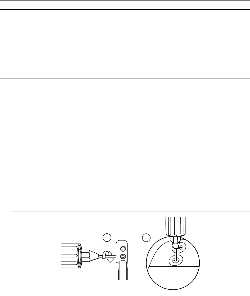
Table 3. Acceptable sensing and pacing values
Measurements required Acute transvenous leads Chronic leadsa
P-wave EGM amplitude (atrial) ≥ 2 mV ≥ 1 mV
R-wave EGM amplitude (RV) ≥ 5 mV ≥ 3 mV
Slew rate
≥ 0.5 V/s (atrial) ≥ 0.3 V/s (atrial)
≥ 0.75 V/s (RV) ≥ 0.5 V/s (RV)
Capture threshold (0.5 ms pulse width)
≤ 1.5 V (atrial) ≤ 3.0 V (atrial)
≤ 1.0 V (RV) ≤ 3.0 V (RV)
aChronic leads are leads implanted for 30 days or more.
3.4 Connecting the leads to the device
The following procedure describes how to connect a lead to the device, confirm that the lead connector is fully
inserted in the connector block, and verify that the lead connection is secure.
Warning: After connecting the leads, verify that the lead connections are secure by gently tugging on each lead.
A loose lead connection may result in inappropriate sensing, which can cause false tracking and false inhibition of
pacing.
Caution: Use only the torque wrench supplied with the device. The torque wrench is designed to prevent damage
to the device from overtightening a setscrew.
3.4.1 How to connect a lead to the device
1. Insert the torque wrench into the appropriate setscrew.
a. If the setscrew obstructs the port, retract the setscrew by turning it counterclockwise until the port is clear.
Take care not to disengage the setscrew from the connector block (see Figure 1).
b. Leave the torque wrench in the setscrew until the lead connection is secure. This action allows a pathway
for venting trapped air when the lead connector is inserted into the connector port.
Figure 1. Inserting the torque wrench into the setscrew
1a 1b
2. Push the lead connector into the connector port until the lead connector pin is clearly visible in the pin viewing
area. No sealant is required.
16
3. Confirm that the lead is fully inserted into the connector pin cavity by viewing the device connector block from
the side or end.
a. The lead connector pin should be clearly visible beyond the setscrew block (see Figure 2).
b. The lead connector ring should be completely inside the spring contact block. There is no setscrew in this
location (see Figure 2).
Figure 2. Confirming the lead connection
3b
3a
4. Tighten the setscrew by rotating it clockwise until the torque wrench clicks. Remove the torque wrench.
5. Gently tug on the lead to confirm a secure fit. Do not pull on the lead until the setscrew has been tightened.
6. Repeat these steps for each lead.
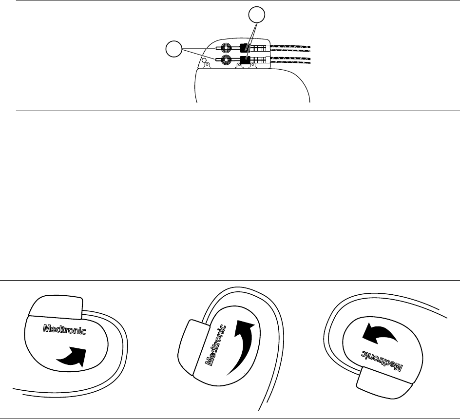
3.5 Positioning and securing the device
Note: Implant the device within 4 cm of the surface of the skin to optimize post-implant ambulatory monitoring.
3.5.1 How to position and secure the device
1. Verify that each lead connector pin is fully inserted into the connector port and that all setscrews are tight.
2. To prevent twisting of the lead body, rotate the device to loosely wrap the excess lead length (see Figure 3).
Do not kink the lead body.
Figure 3. Rotating the device to wrap the leads
3. Place the device and the leads into the surgical pocket.
4. Use nonabsorbable sutures to secure the device within the pocket and minimize post-implant rotation and
migration. Use a surgical needle to penetrate the suture hole on the device.
5. Suture the pocket incision closed.
17
3.6 Completing the implant procedure
3.6.1 How to complete programming the device
1. If unipolar leads are implanted, you may want to manually complete the Implant Detection process.
a. Select the Params icon.
b. Program the Pace Polarity and Sense Polarity parameters to Unipolar.
c. Select Additional Features… and program the Implant Detection parameter to Off/Complete.
2. Verify that the pacing and detection parameters are programmed to values that are appropriate for the patient.
3. Enter the patient’s information.
Note: Be sure to use the Patient Information screen to enter complete information about the implanted leads.
Be sure to use the MRI SureScan System/Other Hardware screen to enter complete information about other
hardware implanted in the patient, including abandoned devices or leads, and lead extenders or adaptors.
This information will be used in the future if the patient needs to be evaluated for an MRI scan. For more
information, see the programming guide.
4. Program the Medtronic CareAlert parameters, if applicable.
5. Program the Data Collection Setup parameters.
3.6.2 How to assess the performance of the device and leads
After implanting the device, x-ray the patient as soon as possible to verify device and lead placement. Before the
patient is discharged from the hospital, assess the performance of the implanted device and leads.
1. Monitor the patient’s electrocardiogram until the patient is discharged. If a lead dislodges, it usually occurs
during the immediate postoperative period.
2. Check the pacing and sensing values, and adjust the values if necessary. Verify the safety margin for the
pacing threshold.
3. Interrogate the device, and print a Final Report to document the postoperative programmed device status.
3.7 Replacing a device
To retain the ability to safely scan the SureScan pacing system during MRI scans, the MRI conditions for use in
Section 1.6, “MRI conditions for use”, page 6 must be followed. Refer to the Medtronic MRI technical manual for
additional information.
Warning: Bipolar or unipolar leads may be used with the Azure S DR MRI SureScan Model W3DR01 device, but
if leads other than bipolar SureScan leads are used, the system is not approved for MRI scans. Before performing
an MRI scan, refer to the Medtronic MRI technical manual for additional information.
Warning: Abandoned leads or previously implanted non-MRI labeled leads compromise the ability to safely scan
the SureScan pacing system during future MRI scans. When implanting a SureScan pacing system, consider the
risks associated with removing previously implanted leads before removing the leads to maintain the ability to
safely scan the SureScan pacing system. Refer to the Medtronic MRI technical manual for additional information.
Warning: Keep external pacing equipment nearby for immediate use. The patient does not receive pacing therapy
from the device when the lead is disconnected, or when the device is removed from the pocket while the device
is operating in unipolar pacing mode.
Caution: Unipolar atrial leads may be used with the device, but bipolar atrial leads are recommended. If unipolar
atrial leads are used, the Capture Management feature must be programmed to Off.
Note: To meet the implant requirements, you may need to reposition or replace the chronic leads. For more
information, see Section 3.2, “Selecting and implanting the leads”, page 14.
18

Note: Any unused leads that remain implanted must be capped with a lead pin cap to avoid transmitting electrical
signals. Contact your Medtronic representative for information about lead pin caps. Any capped or unused leads
are considered abandoned leads in the MRI conditions for use, and their presence will contraindicate the system
for MRI scanning.
3.7.1 How to explant and replace a device
1. Program the device to a mode that is not rate-responsive to avoid potential rate increases while explanting the
device.
2. Dissect the leads and the device free from the surgical pocket. Do not nick or breach the lead insulation.
3. Use a torque wrench to loosen the setscrews in the connector block.
4. Gently pull the leads out of the connector ports.
5. Evaluate the condition of each lead (see Section 3.3, “Testing the lead system”, page 15). Replace a lead if
the electrical integrity is not acceptable or if the lead connector pin is pitted or corroded. If you explant the lead,
return the lead to Medtronic for analysis and disposal.
6. Connect the leads to the replacement device (see Section 3.4, “Connecting the leads to the device”,
page 16).
Note: Lead adaptors may be needed to connect the leads to the replacement device. Contact a Medtronic
representative for information about compatible lead adaptors.
Note: Lead adaptors compromise the ability to safely perform an MRI scan on the SureScan pacing system
in the future. Patients with lead adaptors are contraindicated for an MRI scan.
7. Position and secure the device in the surgical pocket, and suture the pocket incision closed (see Section 3.5,
“Positioning and securing the device”, page 17).
8. Contact Medtronic for Return Mailer Kits to return explanted devices for analysis and disposal. See the back
cover for addresses.
4 Product specifications
4.1 Physical characteristics
Table 4. Physical characteristics
Volumea12.75 cm3
Mass 22.5 g
H x W x Db46.6 mm x 50.8 mm x 7.4 mm
Radiopaque IDcRNA
Medtronic identifier
Surface area of titanium device can 33.48 cm2
Materials in contact with human tissuedTitanium, polyurethane, silicone rubber
Battery Lithium-hybrid CFx silver vanadium oxide
aVolume with connector holes unplugged.
bGrommets may protrude slightly beyond the can surface.
cThe radiopaque ID, which includes a Medtronic-identifier symbol, can be viewed in a fluoroscopic image of the
device.
dThese materials have been successfully tested for the ability to avoid biological incompatibility. The device does
not produce an injurious temperature in the surrounding tissue during normal operation.
19
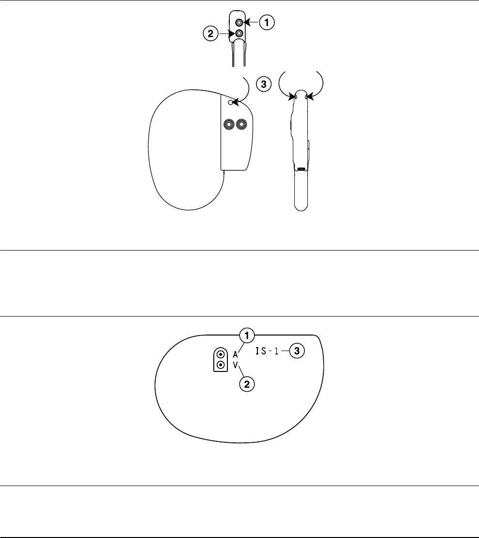
Figure 4. Connector and suture hole
1 IS-1 connector port, A
2 IS-1 connector port, V
3 Suture hole
The Model W3DR01 shield graphics are shown in Figure 5.
The IS-1 marking in Figure 5 indicates that the lead connectors conform to ISO 5841-3.
Figure 5. Shield graphics: Model W3DR01
1 A = atrial
2 V = ventricular
3 IS-1 marking
4.2 Electrical specifications
Table 5. Battery characteristics
Manufacturer Medtronic Energy and Component Center
Model Delta 26H3
Number of battery cells 1
Chemistry Lithium-hybrid CFx silver vanadium oxide
20
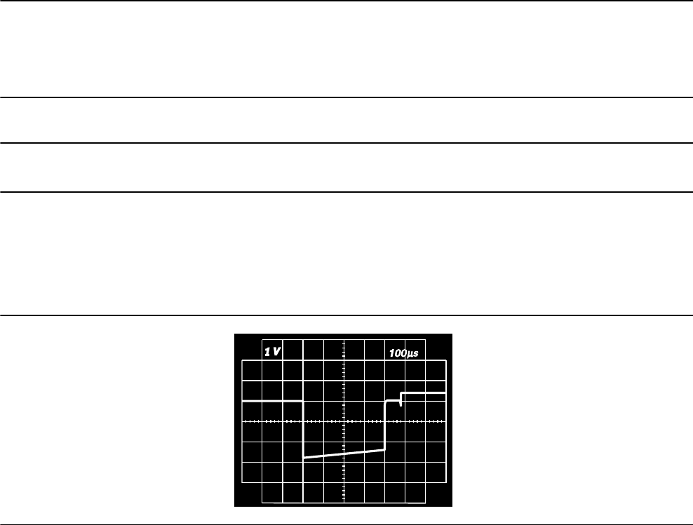
Table 5. Battery characteristics (continued)
Nominal voltage 3.25 V
Mean usable capacity 1.2 Ah
Mean capacity to RRT 0.97 Ah
Residual usable capacity at RRT 0.23 Ah
Table 6. Current consumption
Current consumption (at 100% pacing)a10.40 µA
Current consumption (at 100% inhibition)b6.71 µA
aCurrent consumption when pacing into 500 Ω ± 1% loads at the Beginning of Service in DDDR mode at
60 min–1, 2.5 V, 0.4 ms.
bCurrent consumption when at the Beginning of Service in DDDR mode at 60 min–1, 2.5 V, 0.4 ms, 500 Ω ± 1%.
4.2.1 Output waveforms
Figure 6. Output waveform at nominal conditions (resistive load: 500 Ω)
4.2.2 Measuring methods
Device parameters, such as pulse duration, pulse amplitude, and sensitivity (sensing threshold), are measured
according to the standard ISO 14708-2:2012.
Pulse duration – Pulse duration is measured at 10% of the programmed amplitude and 90% of the trailing edge
amplitude according to the standard ISO 14708-2:2012. See Figure 7. (See Figure 8 for definitions of amplitude
measurements.)
Pulse amplitude – The peak pulse amplitude is measured according to the standard ISO 14708-2:2012.
Sensitivity (sensing threshold) – Ventricular sensitivity is defined as the voltage amplitude of a standard ISO
14708-2:2012 test signal that is just sufficient to be sensed by the device. The signal from a test signal generator
used for the exact determination of sensitivity (sensing threshold) is illustrated in Figure 9.
Notes:
●When measuring the pacing and sensing parameters with pacing system analyzers, considerable differences
may be observed with the specifications presented in this manual. This is because the measuring methods
employed by such systems may differ from those described above.
●Lead impedance measurement results may be distorted by electrocardiogram monitoring equipment.
21
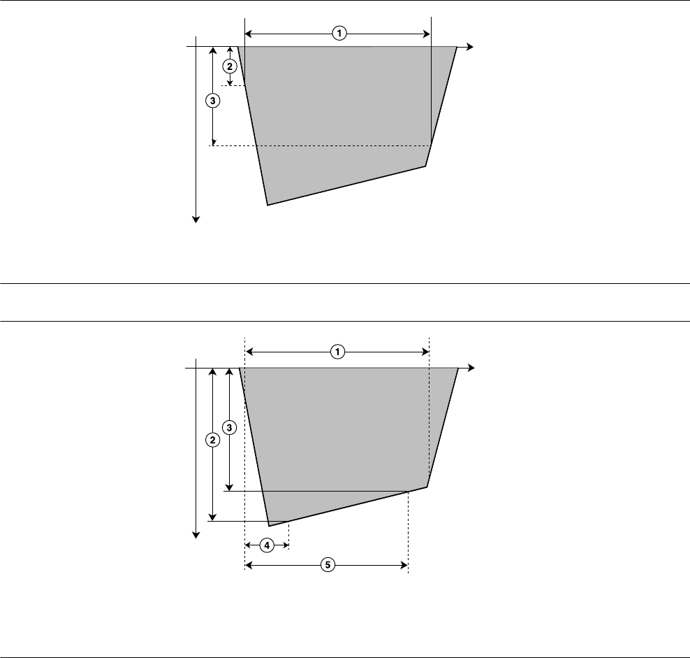
Figure 7. Measurement of pulse duration
t (ms)
1 Pulse duration
2 10% of the programmed amplitude
3 90% of the trailing edge amplitude (90% A s)
Figure 8. Measurement of pulse amplitude
t (ms)
1 Pulse duration
2 Pulse amplitude (Amax)
3 Trailing edge amplitude (As)
4 Voltage sample Amax is taken at time t1 = 10 µs.
5 Voltage sample As is taken at time t2, which is the
programmed pulse duration value –30 µs.
22

Figure 9. Measurement of sensitivity
t (ms)
1 T = 15 ms ±1 ms
2 t = 2 ms ±0.2 ms
3 Signal amplitude AT
Note: The signal may be either positive or negative.
4.2.3 Variation with temperature
Basic rate, test pulse rate, pulse duration, and pulse amplitude remain within expected tolerances when the device
temperature is between 22°C and 45°C. Sensitivity at nominal conditions as measured at 37°C can vary as much
as ±1% per°C from 22°C to 45°C.
4.3 Replacement indicators
The battery voltage and messages about replacement status appear on the programmer display and on printed
reports. The Recommended Replacement Time (RRT), Elective Replacement Indicator (ERI), and the End of
Service (EOS) conditions are listed in Table 7.
Table 7. Replacement indicators
Recommended Replacement Time (RRT) ≤ 2.63 V on 3 consecutive daily automatic measure-
ments
Elective Replacement Indicator (ERI) 3 months after RRT
End of Service (EOS) 3 months after ERI
RRT date – The programmer displays the date when the battery reached RRT on the Quick Look II and Battery and
Lead Measurements screens.
Replace at EOS – If the programmer indicates that the device is at EOS, replace the device immediately.
RRT operation – When the device reaches RRT, it continues to operate with its programmed parameters.
However, placing a magnet over the device initiates asynchronous pacing at 65 min–1 rather than at 85 min–1.
ERI operation – When the device reaches ERI, it automatically changes the value of several parameters as shown
in Table 8.
23

Table 8. Parameter settings after ERI
Pacing Mode VVI
Lower Rate 65 min–1
RV Amplitude as programmed
RV Pulse Width as programmed
Rate Hysteresis Off
Sleep Off
Pre-arrhythmia EGM Offa
aPre-arrhythmia EGM cannot be reprogrammed after ERI.
Note: After ERI, all pacing parameters can be programmed, including mode and rate. Reprogramming the pacing
parameters may reduce the duration of the ERI to EOS period.
Note: When the MRI SureScan mode is programmed to On, battery measurements are taken, but the device does
not report RRT, EOS, or ERI until the MRI SureScan mode has been programmed to Off.
Prolonged Service Period – The Prolonged Service Period (PSP) is the time between the RRT and EOS. The
PSP is defined as 6 months assuming the following conditions: 100% DDD pacing at 60 min–1, 2.5 V atrial and RV
pacing amplitude; 0.4 ms pulse width; and 600 Ω pacing load. The EOS may be indicated before the end of 6
months if the device exceeds these conditions.
4.4 Projected service life
The projected service life in years for the device is shown in Table 9. The data is based on pacing outputs
programmed to the specified amplitude and 0.4 ms pulse width and 60 min–1 pacing rate.
The service life of the device is affected by the programmed settings for certain features, such as Pre-arrhythmia
EGM storage.
Projected service life estimates are based on accelerated battery discharge data and device modeling as
specified. These values should not be interpreted as precise numbers.
Table 9. Projected service life in years
Pacing
Pre-arrhythmia
EGM storagea
500 Ω pacing
impedance
600 Ω pacing
impedance
900 Ω pacing
impedance
2.5 V 3.5 V 2.5 V 3.5 V 2.5 V 3.5 V
DDD, 0% Off 15.8 15.8 15.8 15.8 15.8 15.8
On 15.7 15.7 15.7 15.7 15.7 15.7
DDD, 15% Off 14.6 13.6 14.8 13.9 15.1 14.4
On 14.5 13.5 14.7 13.8 15.0 14.3
DDD, 50% Off 12.4 10.2 12.8 10.8 13.6 11.9
On 12.3 10.1 12.7 10.7 13.5 11.9
AAI<=>DDD
(MVP Mode)
50% Atrial,
5% Ventricular
Off 13.7 12.1 14.0 12.6 14.5 13.4
On 13.6 12.1 13.9 12.5 14.4 13.3
24

Table 9. Projected service life in years (continued)
Pacing
Pre-arrhythmia
EGM storagea
500 Ω pacing
impedance
600 Ω pacing
impedance
900 Ω pacing
impedance
2.5 V 3.5 V 2.5 V 3.5 V 2.5 V 3.5 V
DDD, 100% Off 10.2 7.5 10.8 8.1 12.0 9.6
On 10.1 7.4 10.7 8.1 11.9 9.5
aThe data provided for programming Pre-arrhythmia EGM storage to On is based on a 6-month period (two
3-month follow-up intervals) over the life of the device. Additional use of Pre-arrhythmia EGM storage reduces
projected service life by approximately 12.1% or 1.4 months per year.
Note: These projections are based on typical shelf storage time (5 months). Assuming worst-case shelf storage
time (18 months), longevity is reduced by approximately 7%.
Note: The Capture Management feature can independently adapt each pacing amplitude value. An Atrial Pacing
Amplitude of 1.5 V and an RV Pacing Amplitude of 2.0 V represent typical values when using the Capture
Management feature. At these settings, and with 100% ventricular pacing (at 60 min–1, 0.4 ms, and 600 Ω), the
projected service life of the device is 12.6 years.
Medtronic remote monitor transmissions – Additional remote monitoring transmissions reduce the projected
service life of the device. For example, from nominal pacing (at 2.5 V, 0.4 ms, 600 Ω, 60 min–1, 100% atrial and
ventricular pacing), a patient can expect a projected service life of 10.7 years. More frequent remote monitoring
transmissions will reduce this projected service life as follows:
●Monthly transmissions over the life of the device reduce projected service life by 16 days, or <1%.
●Weekly transmissions over the life of the device reduce projected service life by 87 days, or 2.2%.
●Daily transmissions over the life of the device reduce projected service life by 564 days, or 14.4%.
Table 10. Projected service life in years per conditions specified in EN 45502-2-1 and ISO 14708-2
EN 45502-2-1 ISO 14708-2
500 Ω ±1% pacing impedance
70 min–1
600 Ω ±1% pacing impedance
60 min–1
Pacing
DDDR, 100%
2.5 V, 0.5 ms 8.7a—
5.0 V, 0.5 ms 3.8a—
2.5 V, 0.4 ms — 10.7a
5.0 V, 0.4 ms — 5.5a
aData storage and diagnostic functions applicable to the pacing mode are On.
25

5 Device parameters
5.1 Emergency settings
Table 11. Emergency VVI settings
Parameter Selectable values
Pacing Mode VVI
Lower Rate 70 min–1
RV Amplitudea6 V
RV Pulse Widtha1.5 ms
RV Pace Polarity Unipolar
V. Blank Post VP 240 ms
Rate Hysteresis Off
MRI SureScan Off
aIf the programmed RV Amplitude is 8 V, VVI pacing is delivered at 8 V with a pulse width of 1.2 ms.
5.2 Magnet application
When a magnet is placed near the device, the pacing mode changes from the programmed mode to DOO, VOO,
or AOO, and the pacing rate changes to 100 min–1 for 5 beats and then changes to 85 min–1 (±2 min–1) or
65 min–1(±2 min–1), as described at the end of this section. Placing a magnet near the device suspends
tachyarrhythmia detection. When the magnet is removed, the device returns to its programmed operation.
Note: Magnet operation does not occur if telemetry between the device and programmer is established or if the
MRI SureScan mode is programmed to On.
The pacing mode will be DOO when the programmed pacing mode is a dual chamber mode or an MVP mode
(AAIR<=>DDDR, AAI<=>DDD), VOO when the programmed pacing mode is a single chamber ventricular mode,
and AOO when the programmed pacing mode is a single chamber atrial mode.
The pacing rate will be 85 min–1 (700 ms) if the device conditions are normal and it will be 65 min–1 (920 ms) if a
Recommended Replacement Time (RRT) indicator or a device reset has occurred.
5.3 Tachyarrhythmia detection parameters
Table 12. Tachyarrhythmia detection parameters
Parameter Programmable values Shipped Reset
AT/AF Detection Monitor Monitor Monitor
AT/AF Interval (Rate)a150; 160 … 350 … 450 ms 350 ms 350 ms
VT Monitor Monitor ; Off Monitor Off
VT Monitor Interval (Rate)a280; 290 … 400 … 500 ms 400 ms 400 ms
26

Table 12. Tachyarrhythmia detection parameters (continued)
Parameter Programmable values Shipped Reset
RV Sensitivityb,c,d 0.45; 0.60 mV (±50%);
0.90; 1.20; 2.00; 2.80; 4.00; 5.60;
8.00; 11.30 mV (±30%)
Bipolar: 0.9 mV
Unipolar: 2.80 mV
0.9 mV 2.8 mV
Atrial Sensitivityb,d,e 0.15 mV (±75%);
0.30; 0.45; 0.60 mV (±50%);
0.90; 1.20; 1.5; 1.8; 2.1; 4.0 mV
(±30%); Off
Bipolar: 0.3 mV
Unipolar: 0.45 mV
0.3 mV 0.45 mV
aThe measured intervals are truncated to a 10 ms multiple (for example, 457 ms becomes 450 ms). The device
uses this truncated interval value when applying the programmed criteria and calculating interval averages.
bThis setting applies to all sensing in this chamber for both tachyarrhythmia detection and bradycardia pacing
operations.
cThe device complies with the requirements of ISO 14708-2 when the sensitivity threshold is programmed to
2.0 mV or higher.
dTolerances are based on bipolar polarity.
eThe device complies with the requirements of ISO 14708-2 when the sensitivity threshold is programmed to
1.8 mV or higher.
5.4 Pacing parameters
Table 13. Modes, rates, and intervals
Parameter Programmable values Shipped Reset
Mode DDDR; DDD; AAIR<=>DDDR ;
AAI<=>DDD; DDIR; DDI; AAIR; AAI;
VVIR; VVI; DOO; AOO; VOO; ODO
AAI<=>DDD VVI
Mode Switch On ; Off On Off
Lower Ratea30; 35 … 60 ; 70; 75 … 150 min–1
(±2 min–1)
60 min–1
(1000 ms)
65 min–1
(920 ms)
Upper Tracking Rate 80; 85 … 130 …175 min–1 (±2 min–1);
180; 190 … 210 min–1 (+2/-11 min–1)
130 min–1 120 min–1
Paced AV 30; 40 … 180 … 350 ms (±4 ms) 180 ms 180 ms
Sensed AV 30; 40 … 150 … 350 ms (+30; –2 ms) 150 ms 150 ms
Maximum AV Interval limit Off ; 250; 260 … 500 Off Off
PVARP Auto ; 150; 160 … 500 ms (+5; –30 ms) Auto Auto
Minimum PVARP 150; 160 … 250 … 500 ms (+5; –30 ms) 250 ms 250 ms
A. Refractory Period 150; 160 … 310 … 500 ms (+5; –30 ms) 310 ms 310 ms
aThe corresponding Lower Rate interval can be calculated as follows: Lower Rate interval (ms) = 60,000/Lower
Rate.
27

Table 14. Atrial parameters
Parameter Programmable values Shipped Reset
Atrial Amplitude 0.5; 0.75 … 1.25 V (+0.125 V / -33%)
1.50 … 3.5 … 5; 5.5; 6; 8 V
(+15% / -33%)a
3.5 V —
Atrial Pulse Width 0.03; 0.06 ms (±10 µs);
0.1; 0.2; 0.3; 0.4 … 1.5 ms (±25 µs)
0.4 ms —
Atrial SensitivitybOff; 0.15 mV (±75%);
0.3; 0.45; 0.6 mV (±50%);
0.9; 1.2; 1.5; 1.8; 2.1; 4.0 mV (±30%)
Unipolar: 0.45 mV
Bipolar: 0.3 mV
0.3 mV 0.45 mV
Atrial Pace Polarity Bipolar; Unipolar Configurec—
Atrial Sense Polarity Bipolar; Unipolar ConfigurecUnipolar
Atrial Lead Monitor Monitor Only; Adaptive Monitor Only Monitor Only
Min Limit 200 ; 300; 400; 500 Ω 200 Ω 200 Ω
Max Limit 1000; 1500; 2000; 3000 Ω 3000 Ω 3000 Ω
aWhen Atrial Amplitude is 8 V, Atrial Pulse Width must be less than 1.3 ms.
bThis setting applies to all sensing in this chamber for both tachyarrhythmia detection and bradycardia pacing
operations.
c“Configure” is displayed when the device is automatically configuring the lead polarity at implant. It is not a
selectable value.
Table 15. RV parameters
Parameter Programmable values Shipped Reset
RV Amplitude 0.5; 0.75 … 1.25 V (+0.125 V / -33%)
1.50 … 3.5 … 5; 5.5; 6; 8 V
(+15% / -33%)a
3.5 V 6 V
RV Pulse Width 0.03; 0.06 ms (±10 µs);
0.1; 0.2; 0.3; 0.4 … 1.5 ms (±25 µs)
0.4 ms 1.5 ms
RV Sensitivityb0.45; 0.60 mV (±50%);
0.90 ; 1.20; 2.00; 2.80; 4.00; 5.60; 8.00;
11.30 mV (±30%)
Unipolar: 2.80 mV
Bipolar: 0.90 mV
0.90 mV 2.80 mV
RV Pace Polarity Bipolar; Unipolar ConfigurecUnipolar
RV Sense Polarity Bipolar; Unipolar ConfigurecUnipolar
RV Lead Monitor Monitor Only; Adaptive Monitor Only Monitor Only
Min Limit 200 ; 300; 400; 500 Ω 200 Ω 200 Ω
Max Limit 1000; 1500; 2000; 3000 Ω 3000 Ω 3000 Ω
aWhen RV Amplitude is 8 V, RV Pulse Width must be less than 1.3 ms.
bThis setting applies to all sensing in this chamber for both tachyarrhythmia detection and bradycardia pacing
operations.
c“Configure” is displayed when the device is automatically configuring the lead polarity at implant. It is not a
selectable value.
28
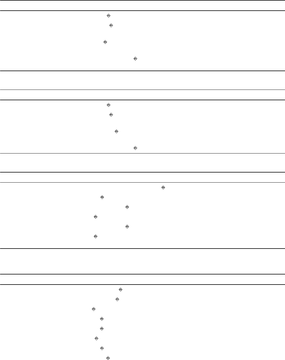
Table 16. Atrial Capture Management parameters
Parameter Programmable values Shipped Reset
Atrial Capture Management Adaptive ; Monitor; Off Adaptive Off
Atrial Amplitude Safety
Margin
1.5x; 2.0x ; 2.5x; 3.0x 2.0x 2.0x
Atrial Minimum Adapted
Amplitude
1.0; 1.5 ; 2.0; 2.5; 3.0; 3.5 V 1.5 V 1.5 V
Atrial Acute Phase Remain-
ing
Off; 30; 60; 90; 120 ; 150 days 120 days 120 days
Table 17. RV Capture Management parameters
Parameter Programmable values Shipped Reset
RV Capture Management Adaptive ; Monitor; Off Adaptive Off
RV Amplitude Safety Mar-
gin
1.5x; 2.0x ; 2.5x; 3.0x 2.0x 2.0x
RV Minimum Adapted
Amplitude
1.0; 1.5; 2.0 ; 2.5; 3.0; 3.5 V 2 V 2 V
RV Acute Phase Remaining Off; 30; 60; 90; 120 ; 150 days 120 days 120 days
Table 18. Blanking periods
Parameter Programmable values Shipped Reset
PVAB Interval 10a; 20 … 100; 110; 120 …150 … 300 ms 150 ms 150 ms
PVAB Method Partial ; Partial+; Absolute Partial Partial
A. Blank Post AP 150; 160 … 200 … 250 ms (+5; −30 ms) 200 ms 240 ms
A. Blank Post AS 100 ; 110 … 170 ms (+2; −30 ms) 100 ms 100 ms
V. Blank Post VP 150; 160 … 200 … 320 ms (+5; −30 ms) 200 ms 240 ms
V. Blank Post VS 120 ; 130 … 170; 200; 220; 250; 280; 300;
320 ms (+2; −30 ms)
120 ms 120 ms
aIf the PVAB Method is set to Partial, the minimum selectable value for the PVAB Interval is 100 ms
Table 19. Rate Response Pacing parameters
Parameter Programmable values Shipped Reset
Upper Sensor Rate 80; 85 … 130 … 175 min–1 (±2 min–1) 130 min–1 120 min–1
ADL Rate 60; 65 … 95 … 170 min–1 (±2 min–1) 95 min–1 95 min–1
Rate Profile Optimization On ; Off On Off
ADL Response 1; 2; 3 ; 4; 5 3 3
Exertion Response 1; 2; 3 ; 4; 5 3 3
Activity Threshold Low ; Medium Low; Medium High; High Low Medium Low
Activity Acceleration 15; 30 ; 60 s 30 s 30 s
Activity Deceleration Exercise ; 2.5; 5; 10 min Exercise 5 min
29
Table 19. Rate Response Pacing parameters (continued)
Parameter Programmable values Shipped Reset
ADL Setpoint 5; 6 … 40; 42 … 80 18 18
UR Setpoint 15; 16 … 40; 42 … 80; 85 … 180 40 40
Table 20. Rate Adaptive AV parameters
Parameter Programmable values Shipped Reset
Rate Adaptive AV Off ; On Off On
Start Rate 50; 55 … 90 … 145 min–1 90 min–1 60 min–1
Stop Rate 55; 60 … 130 … 175 min–1 130 min–1 120 min–1
Minimum Paced AV 30; 40 … 140 … 200 ms 140 ms 140 ms
Minimum Sensed AV 30; 40 … 110 … 200 ms 110 ms 110 ms
Table 21. Atrial Preference Pacing parameters
Parameter Programmable values Shipped Reset
A. Preference Pacing On; Off Off Off
Maximum Rate 80; 85 … 100 … 150 min–1 100 min–1 100 min–1
Interval Decrement 30 ; 40; 50 … 100; 150 ms 30 ms 50 ms
Search Beats 5; 10; 15; 20 … 25; 50 20 5
Table 22. Rate Drop Response parameters
Parameter Programmable values Shipped Reset
Rate Drop ResponseaOn; Off Off Off
Detection Type Drop ; Low Rate; Both Drop Drop
Drop Detection
Drop Size 10; 15 … 25 … 50 min–1 25 min–1 25 min–1
Drop Rate 30; 40 … 60 … 100 min–1 60 min–1 60 min–1
Detection Window 10; 15; 20; 25; 30 s
1 ; 1.5; 2; 2.5 min
1 min 1 min
Low Rate Detection
Detection Beats 1; 2; 3 beats 3 beats 3 beats
Intervention
Intervention Rate 70; 75 … 100 … 150 min–1 100 min–1 100 min–1
Intervention Duration 1; 2 … 15 min 2 min 2 min
aWhen Rate Drop Response is set to On, the lower rate is automatically set to 45 min–1.
30

Table 23. Sleep parameters
Parameter Programmable values Shipped Reset
Sleep On; Off Off Off
Sleep Rate 30; 35 … 50 ; 55; 60; 70; 75 …
100 min–1
50 min–1 50 min–1
Bed Time 00:00; 00:10 … 22:00 … 23:50 22:00 22:00
Wake Time 00:00; 00:10 … 07:00 … 23:50 07:00 07:00
Table 24. Non-Competitive Atrial Pacing (NCAP) parameters
Parameter Programmable values Shipped Reset
Non-Comp Atrial Pacing On ; Off On On
NCAP Interval 200; 250; 300 ; 350; 400 ms 300 ms 300 ms
Table 25. MRI SureScan parameters
Parameter Programmable values Shipped Reset
MRI SureScan On; Off Off Off
MRI Pacing Mode DOO; AOO; VOO; ODO — —
MRI Pacing Rate 60; 70; 75; 80 … 120 min–1 — —
Table 26. Additional pacing features
Parameter Programmable values Shipped Reset
PMT Intervention On; Off Off Off
PVC Response On ; Off On On
V. Safety Pacing On ; Off On On
Rate Hysteresis Off ; 30; 40 … 80 min–1 Off Off
5.5 Data collection parameters
Table 27. Data collection parameters
Parameter Programmable values Shipped Reset
EGM 1 Source Can to Aring; Can to RVring; Atip to Aring ;
Atip to RVring; Atip to Can; Aring to RVring;
RVtip to RVring; RVtip to Can
Atip to Aring Atip to Aring
EGM 1 Range ±1; ±2; ±4; ±8 ; ±12; ±16; ±32 mV ±8 mV ±8 mV
EGM 2 Source Can to RVring; RVtip to RVring ; RVtip to
Can
RVtip to RVring RVtip to RVring
EGM 2 Range ±1; ±2; ±4; ±8 ; ±12; ±16; ±32 mV ±8 mV ±8 mV
EGM 3 Source RVtip to RVring; Can to RVring ; Atip to
RVring; Atip to Aring; Can to Aring
Can to RVring Can to RVring
31

Table 27. Data collection parameters (continued)
Parameter Programmable values Shipped Reset
EGM 3 Range ±1; ±2; ±4; ±8 ; ±12; ±16; ±32 mV ±8 mV ±8 mV
Monitored EGM1 and EGM2 ; EGM1 and EGM3;
EGM2 and EGM3
EGM1 and
EGM2
EGM1 and EGM2
Pre-arrhythmia
EGM
Off ; On – 1 month; On – 3 months; On Con-
tinuous
Off Off
Device Date/Timea(select Time Zone) — —
Holter Telemetry Off ; 0.5; 1; 2; 4; 8; 16; 24; 36; 46 hr Off Off
Wireless Teleme-
try with Monitor
On; Off On Onb
aThe times and dates stored in episode records and other data are determined by the Device Date/Time clock.
bThe reset value may be set to Off if there is an issue with wireless communication that requires it to be disabled.
5.6 Medtronic CareAlert parameters
Table 28. Clinical Management Alerts
Parameter Programmable values Shipped Reset
AT/AF Burden and Rate Settings…
AT/AF Alerts
AT/AF Daily Burden Enable Off ; On Off Off
Daily AT/AF Burden (hr/24hr) 0.5; 1; 2; 6 ; 12; 24 hr/24 hr 6 hr 6 hr
Avg. V. Rate During AT/AF Ena-
ble
Off ; On Off Off
Daily Burden for Avg. V. Rate
(hr/24hr)
0.5; 1; 2; 6 ; 12; 24 hr/24 hr 6 hr 6 hr
Avg. V. Rate During AT/AF
(min–1)
90; 100 … 150 min–1 100 min–1 100 min–1
Monitored VT Episode Detec-
ted
Off ; On Off Off
Cumulative Right Ventricular
Pacing > 40%a
Off ; OnbOff Off
aThere is no observation for Cumulative Right Ventricular Pacing > 40%.
bAlert triggered if cumulative percent of right ventricular pacing exceeds 40% for 7 consecutive days.
Table 29. Lead/Device Integrity Alerts
Parameter Programmable values Shipped Reset
Low Battery Voltage RRT On ; Off On Off
Lead Impedance Out of Range…
Lead Impedance
A. Pacing Enable On ; Off On Off
A. Pacing Less than 200 ; 300; 400; 500 Ω 200 Ω 200 Ω
32

Table 29. Lead/Device Integrity Alerts (continued)
Parameter Programmable values Shipped Reset
A. Pacing Greater than 1000; 1500; 2000; 3000 Ω 3000 Ω 3000 Ω
RV Pacing Enable On ; Off On Off
RV Pacing Less than 200 ; 300; 400; 500 Ω 200 Ω 200 Ω
RV Pacing Greater than 1000; 1500; 2000; 3000 Ω 3000 Ω 3000 Ω
Capture Management High Threshold
High Threshold
A. Capture EnableaOff ; On Off Off
RV Capture EnablebOff ; On Off Off
aIf programmed to On, alert notification is sent if A. capture management has measured high thresholds for 3
consecutive days.
bIf programmed to On, alert notification is sent if RV capture management has measured high thresholds for 3
consecutive days.
5.7 System test parameters
Table 30. System test parameters
Parameter Selectable values
Pacing Threshold Test parameters
Test Type Amplitude; Pulse Width
Chamber Atrium; RV
Decrement after 2; 3 … 15 pulses
Modea (RV test) VVI; VOO; DDI; DDD; DOO
Modea (Atrium test) AAI; AOO; DDI; DDD; DOO
Lower Rate 30; 35 … 60; 70; 75 … 150c min–1
RV Amplitude 0.25; 0.5 … 5; 5.5; 6; 8 V
RV Pulse Width 0.03; 0.06; 0.1; 0.2 … 1.5 ms
A. Amplitude 0.25; 0.5 … 5; 5.5; 6; 8 V
A. Pulse Width 0.03; 0.06; 0.1; 0.2 … 1.5 ms
AV Delayb30; 40 … 350 ms
V. Pace Blanking 150; 160 … 320 ms
A. Pace Blanking 150; 160 … 250 ms
PVARP 150; 160 … 500 ms
Pace Polarity Unipolar; Bipolar
33
Table 30. System test parameters (continued)
Parameter Selectable values
Sensing Test parameters
ModeaAAI; DDD; DDI; VVI; ODO
AV Delayb30; 40 … 350 ms
Lower Ratec30; 35 … 60; 70; 75 … 120 min–1
aThe selectable values for this parameter depend on the programmed pacing mode.
bThe selectable values for this parameter depend on the programmed Lower Rate.
cWhen performing the test in DDD mode, the Lower Rate must be less than the programmed Upper Tracking
Rate.
5.8 EP study parameters
Table 31. Fixed Burst induction parameters
Parameter Selectable values
Resume at Burst Enabled ; Disabled
Chamber RV; Atrium
Interval 100; 110 … 600 ms
Amplitude 1; 2; 3; 4 ; 5; 6; 8 V
Pulse Width 0.10; 0.20 … 0.50 … 1.50 ms
VVI Backup (for atrial Fixed Burst)aOn; Off
Pacing Rate 60; 70 … 120 min–1
V. Amplitudeb0.50; 0.75 … 5.00; 5.50; 6.00; 8.00 V
V. Pulse Widthb0.10; 0.20 … 1.50 ms
aCrosstalk may occur when atrial pacing amplitude is greater than 6 V.
bThe default value for this parameter is set according to the permanently programmed settings for bradycardia
pacing.
Table 32. PES induction parameters
Parameter Selectable values
Resume at Deliver Enabled ; Disabled
Chamber RV; Atrium
#S1 1; 2 … 8 … 15
S1S1 100; 110 … 600 … 2000 ms
S1S2 Off; 100; 110 … 400 … 600 ms
S2S3 Off ; 100; 110 … 600 ms
S3S4 Off ; 100; 110 … 600 ms
Amplitude 1; 2; 3; 4 ; 5; 6; 8 V
Pulse Width 0.10; 0.20 …0.50 … 1.50 ms
34

Table 32. PES induction parameters (continued)
Parameter Selectable values
VVI Backup (for atrial PES)aOn; Off
Pacing Rate 60; 70 … 120 min–1
V. Amplitudeb0.50; 0.75 … 5.00; 5.50; 6.00; 8.00 V
V. Pulse Widthb0.10; 0.20 … 1.50 ms
aCrosstalk may occur when atrial pacing amplitude is greater than 6 V.
bThe default value for this parameter is set according to the permanently programmed settings for bradycardia
pacing.
Table 33. Shared manual ATP therapy parameters
Parameter Selectable values
Minimum Interval (atrial ATP) 100; 110; 120; 130 … 400 ms
Minimum Interval (ventricular ATP) 150; 160 … 200 … 400 ms
Amplitude 1; 2 … 6 ; 8 V
Pulse Width 0.10; 0.20 …1.50 ms
VVI Backup (for atrial ATP therapy)aOn; Off
Pacing Rate 60; 70 … 120 min–1
V Amplitudeb0.50; 0.75 … 5.00; 5.50; 6.00; 8.00 V
V Pulse Widthb0.10; 0.20 … 1.50 ms
aCrosstalk may occur when atrial pacing amplitude is greater than 6 V.
bThe default value for this parameter is set according to the permanently programmed settings for bradycardia
pacing.
Table 34. Manual Ramp therapy parameters
Parameter Selectable values
Chamber Atrium; RV
RV Ramp therapy parameters
# Pulses 1; 2 … 6 … 15
%RR Interval 50; 53; 56; 59; 63; 66 … 84; 88; 91; 94; 97 %
Dec/Pulse 0; 10 ; 20; 30; 40 ms
Atrial Ramp therapy parameters
# Pulses 1; 2 … 6 … 15; 20; 30 … 100
%AA Interval 28; 31; 34; 38; 41 … 59; 63; 66 … 84; 88; 91; 94; 97 %
Dec/Pulse 0; 10 ; 20; 30; 40 ms
35
Table 35. Manual Burst therapy parameters
Parameter Selectable values
# Pulses 1; 2 … 8 … 15
%RR Interval 50; 53; 56; 59; 63; 66 … 84; 88 ; 91; 94; 97%
Table 36. Manual Ramp+ therapy parameters
Parameter Selectable values
# Pulses 1; 2; 3 … 15
R-S1 (%RR) 50; 53; 56; 59; 63; 66 … 75 … 84; 88; 91; 94; 97%
S1-S2 (%RR) 50; 53; 56; 59; 63; 66; 69 … 84; 88; 91; 94; 97%
S2-SN (%RR) 50; 53; 56; 59; 63; 66 … 84; 88; 91; 94; 97%
Table 37. Manual Burst+ therapy parameters
Parameter Selectable values
#S1 Pulses 1; 2 … 6 … 15; 20; 30 … 100
%AA Interval 28; 31; 34; 38; 41 … 59; 63; 66 … 84; 88; 91 ; 94; 97%
S1S2 Off; 28; 31; 34; 38; 41 … 59; 63; 66 … 84 ; 88; 91; 94;
97%
S2S3 Dec Off; 0; 10; 20 … 80 ms
5.9 Nonprogrammable parameters
Table 38. Nonprogrammable parameters
Parameter Value
Premature event threshold for counting PVCs and Runs of PVCs 95%
Fixed blanking periods
Atrial blanking after a paced ventricular event (bipolar atrial sensing) 30 ms
Atrial blanking after a paced ventricular event (unipolar atrial sensing) 40 ms
Ventricular blanking after a paced atrial event (bipolar ventricular sensing) 30 msa
Ventricular blanking after a paced atrial event (unipolar ventricular sens-
ing)
40 ms
Fixed bradycardia pacing parameters
Ventricular Safety Pacing intervalsb110 ms
PVARP value applied by PVC Response and PMT Interventionc400 ms
NCAP value applied by PVC Response and PMT Interventiond400 ms
Hardware parameters
Pacing rate limit (protective feature)e200 min–1f
Input impedance 150 kΩ minimum
Effective pacing capacitance 4 µF (±10%)
36

Table 38. Nonprogrammable parameters (continued)
Parameter Value
Recommended Replacement Time (RRT)
Battery Voltage Threshold ≤ 2.63
a35 ms when the ventricular pacing amplitude is programmed to 8 V.
bThe VSP interval may be shortened from 110 ms to 70 ms automatically by the device at higher pacing rates
when necessary to help support ventricular tachycardia detection.
cPVARP is extended to 400 ms only if the current PVARP is less than 400 ms.
dThe NCAP extension applies only if NCAP is enabled.
eDoes not apply during ventricular safety pacing.
fIf the Upper Tracking Rate is programmed to a value greater than 180 min–1, the pacing rate limit is 230 min–1.
Table 39. Nonprogrammable parameters for the MRI SureScan mode
Parameter Value
Pacing amplitude Programmed pacing amplitude value when >5 V;
5 V when programmed pacing amplitude value is ≤5 V
Pulse width Programmed pulse width value when >1 ms;
1 ms when programmed pulse width value is ≤ 1 ms
Sensitivity Programmed value
Input impedance 150 kΩ
AV interval Programmed PAV value when PAV is ≥50 ms and
≤100 ms;
50 ms when PAV is <50 ms;
110 ms when PAV is >110 ms
Pacing rate limit 200 min–1
Effective pacing capacitance 4 µF (±10%)
Refractory period —
Blanking period
ODO mode Programmed blanking period value
DOO, VOO, and AOO modes —
37

Medtronic, Inc.
710 Medtronic Parkway
Minneapolis, MN 55432
USA
www.medtronic.com
+1 763 514 4000
Authorized Representative in the European
Community
Medtronic B.V.
Earl Bakkenstraat 10
6422 PJ Heerlen
The Netherlands
+31 45 566 8000
Europe/Middle East/Africa
Medtronic International Trading Sàrl
Route du Molliau 31
Case Postale 84
CH-1131 Tolochenaz
Switzerland
+41 21 802 7000
Australia
Medtronic Australasia Pty Ltd
5 Alma Road
Macquarie Park, NSW 2113
Australia
1800 668 670
Canada
Medtronic of Canada Ltd
99 Hereford Street
Brampton, Ontario L6Y 0R3
Canada
+1 905 460 3800
Technical manuals
www.medtronic.com/manuals
© 2016 Medtronic
M964363A001 B
2016-10-20
*M964363A001*