Medtronic BLEIMPLANT2 Percepta CRT-P MRI SureScan, Percepta Quad CRT-P MRI SureScan, Serena CRT-P MRI SureScan, Serena Quad CRT-P MRI SureScan, Solara CRT-P MRI SureScan, Solara Quad CRT-P MRI SureScan User Manual MAPS ID 502472 016

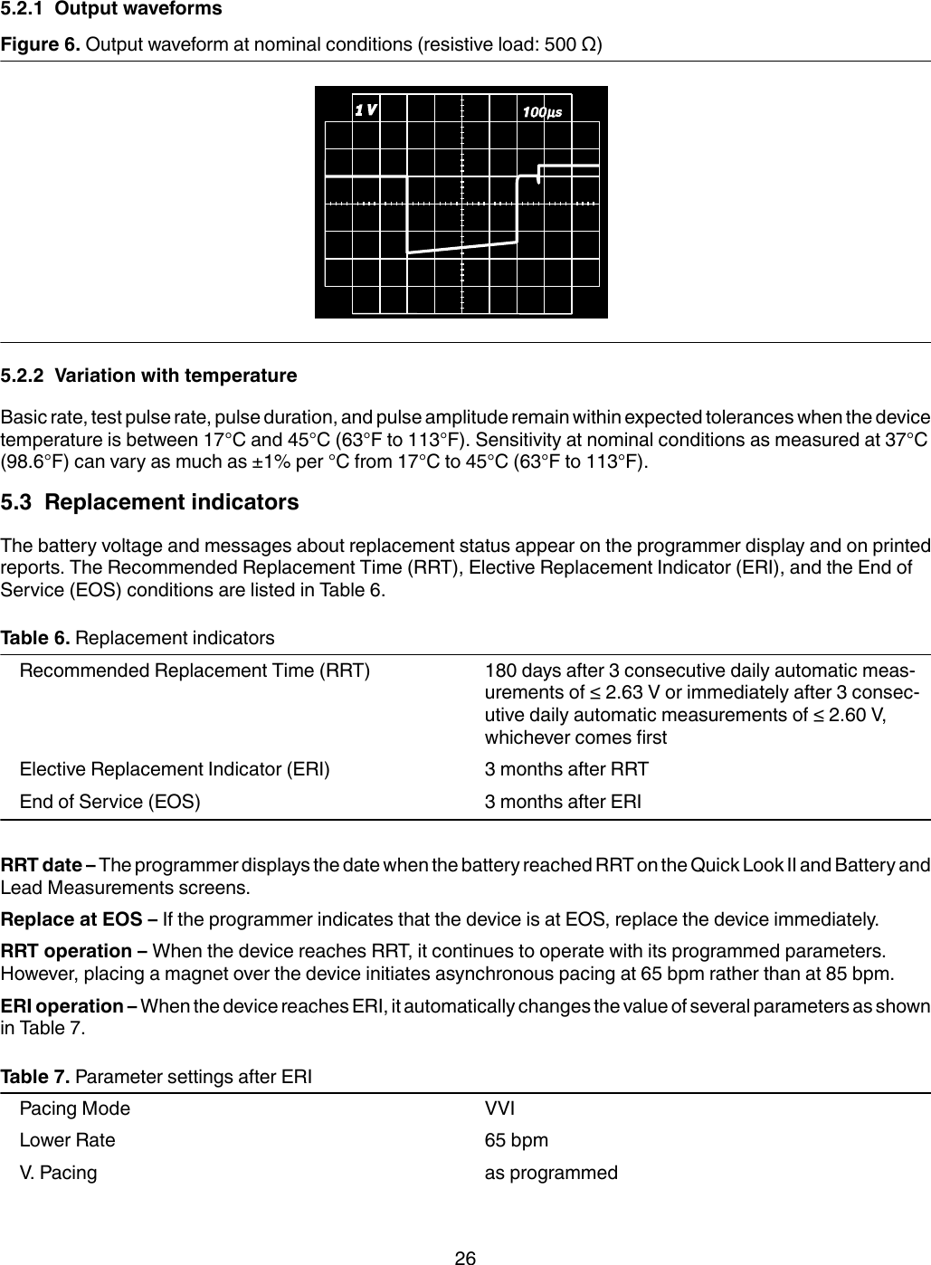
Medtronic, Inc. Percepta CRT-P MRI SureScan, Percepta Quad CRT-P MRI SureScan, Serena CRT-P MRI SureScan, Serena Quad CRT-P MRI SureScan, Solara CRT-P MRI SureScan, Solara Quad CRT-P MRI SureScan MAPS ID 502472 016

User Manual

Percepta™ Quad CRT-P MRI SureScan™ W4TR01MR Conditional pacemaker with cardiac resynchronization therapy, SureScan™ technology,and Bluetooth® wireless telemetry (OAE-DDDR)Device ManualCaution: Federal law (USA) restricts this device to sale by or on the order of a physician.
The following list includes trademarks or registered trademarks of Medtronic in the United States andpossibly in other countries. All other trademarks are the property of their respective owners.AdaptivCRT, Advisa, Advisa DR MRI, Capture Management, Cardiac Compass, CardioSync, CareAlert,CareLink, EffectivCRT, EnPulse, EnRhythm, EnRhythm MRI, Flashback, GEM, GEM III, InSync,InSync II Marquis, InSync III Marquis, InSync Marquis, Kappa, Marquis, Medtronic, Medtronic AT500,Medtronic CareAlert, Medtronic CareLink, MVP, OptiVol, Percepta, Quick Look, Reactive ATP, Revo MRI,SureScan, TherapyGuide, VectorExpress
Contents1 System overview  41.1 Introduction  41.2 System description  41.3 Indications and usage  51.4 Contraindications  51.5 MRI conditions for use  61.6 Feature summary  71.7 Data security  102 Warnings, precautions, and potential adverse events  102.1 General warnings and precautions  102.2 Explant and disposal  102.3 Handling and storage instructions  112.4 Lead evaluation and lead connection  112.5 Device operation  122.6 Potential adverse events  143 Clinical data  153.1 Adverse events and clinical trial data  154 Implant procedure  164.1 Preparing for an implant  164.2 Selecting and implanting the leads  184.3 Testing the lead system  194.4 Connecting the leads to the device  204.5 Positioning and securing the device  214.6 Completing the implant procedure  224.7 Replacing a device  235 Product specifications  245.1 Physical characteristics  245.2 Electrical specifications  255.3 Replacement indicators  265.4 Projected service life  276 Device parameters  296.1 Emergency settings  296.2 Magnet application  296.3 Tachyarrhythmia detection parameters  296.4 Atrial tachyarrhythmia therapy parameters  306.5 Pacing parameters  326.6 Data collection parameters  386.7 Medtronic CareAlert parameters  396.8 System test parameters  406.9 EP study parameters  426.10 Nonprogrammable parameters  453
1  System overview1.1  IntroductionThis manual describes the Medtronic Model W4TR01 Percepta Quad CRT-P MRI SureScan dual chamber,implantable pulse generator with cardiac resynchronization therapy (CRT-P). The manual contains model-specificfeature information, indications and contraindications, warnings and precautions, instructions for implanting thedevice, quick reference specifications, and parameter tables.Additional manuals and documents with information about the device:MRI technical manual – This manual provides MRI-specific procedures and warnings and precautions.Reference manual – This manual contains information about device features. The reference manual applies tomultiple models of CRT-P devices.Programming guide – This manual explains how to use the programmer software to conduct a patient session.Explanation of symbols – This document defines the symbols that may appear on the device package. Refer tothe package label to see which symbols apply specifically to this device.Medical Procedure and EMI Warnings and Precautions Manual for Health Care Professionals – Thismanual provides warnings, precautions, and guidance for health care professionals who perform medicaltherapies and diagnostic procedures on cardiac device patients. The manual also provides patient educationinformation related to sources of electromagnetic interference (EMI) at home, at work, and in other environments.Radio regulatory compliance information – This document provides compliance information related to theradio components of the device.1.2  System descriptionThe Medtronic Percepta Quad CRT-P MRI SureScan Model W4TR01 dual chamber implantable pulse generatorwith cardiac resynchronization therapy (CRT-P) is a multiprogrammable cardiac device that monitors andregulates the patient’s heart rate by providing single or dual chamber rate-responsive bradycardia pacing,sequential biventricular pacing, and atrial tachyarrhythmia therapies. This device features Bluetooth wirelesstechnology.1The MRI SureScan feature permits a mode of operation that allows a patient with a SureScan system to be safelyscanned by an MRI machine while the device continues to provide appropriate pacing. When programmed to On,MRI SureScan operation disables arrhythmia detection, magnet mode, and all user-defined diagnostics. Beforeperforming an MRI scan, refer to the MRI technical manual.The users of this device include medical professionals (physicians, nurses, technicians, and their supporting staff)trained in surgery, cardiology, radiology, and magnetic resonance (MR) technology and able to implement theprocedures documented in the instructions for use for this device.1.2.1  Usage environmentsThe device is intended to be used in the following environments and conditions:●The device will be implanted in a properly equipped, staffed, and sterile surgical environment. Implant will takeplace under standard surgical protocols and in the patient population for which the device is indicated.●Post-surgical patient and device follow-up care will take place in a properly equipped and staffed cardiologyclinic or office.1The Bluetooth® word mark is a registered trademark of Bluetooth SIG, Inc. and any use of this mark byMedtronic is under license.4
●MRI procedures for patients with this device will take place in a properly equipped and staffed MR facility, andin consideration of the conditions and requirements described in Section 1.5, “MRI conditions for use”,page 6.●After having an implant, patients may resume their lives at home, at work, and in other environments withconsideration of the advice and restrictions documented in the Medical Procedure and EMI Warnings andPrecautions Manual for Health Care Professionals and in the patient literature.1.2.2  System components and accessoriesContents of sterile package – The package contains 1 implantable pulse generator with cardiacresynchronization therapy (CRT-P) and 1 torque wrench.Implantable device system – The Percepta Quad CRT-P MRI SureScan Model W4TR01 device and the pacingleads constitute the implantable portions of the device system.Leads – The lead system used with this device must provide pacing to the left ventricle (LV), sensing and pacingto the right ventricle (RV), and sensing and pacing to the atrium (A). Do not use any lead with this device withoutfirst verifying lead and connector compatibility.For information about selecting and implanting SureScan leads for this device, refer to Section 4.2, “Selecting andimplanting the leads”, page 18.Programmers and software – Medtronic programmers and software are used to program this device.Programmers from other manufacturers are not compatible with Medtronic devices, but they do not damageMedtronic devices.Medtronic pacing system analyzer – A pacing system analyzer is used to measure the electrical characteristicsof the implanted leads to assess their effectiveness for pacing and sensing.Medtronic patient monitor – Patients use the Medtronic patient monitor, if available, to gather information fromtheir implanted devices and communicate the information to their physicians through the Medtronic CareLinkNetwork. For information on using the patient monitor, refer to the patient monitor literature.1.3  Indications and usageThe Percepta Quad CRT-P MRI SureScan system is indicated for:●NYHA Functional Class III and IV patients who remain symptomatic despite stable, optimal medical therapyand have LVEF ≤ 35% and a prolonged QRS duration.●NYHA Functional Class I, II, or III patients who have LVEF ≤ 50%, are on stable, optimal heart failure medicaltherapy if indicated and have atrioventricular block (AV block) that are expected to require a high percentageof ventricular pacing that cannot be managed with algorithms to minimize right ventricular pacing.Optimization of heart failure medical therapy that is limited due to AV block or the urgent need for pacing shouldbe done post implant.Rate adaptive pacing is provided for those patients developing a bradycardia indication who might benefit fromincreased pacing rates concurrent with increases in activity.Dual chamber and atrial tracking modes are indicated for patients who may benefit from maintenance of AVsynchrony.Antitachycardia pacing (ATP) is indicated for termination of atrial tachyarrhythmia in patients with one or more ofthe above pacing indications.1.4  ContraindicationsThe Percepta Quad CRT-P MRI SureScan system is contraindicated for:●Concomitant implant with another bradycardia device●Concomitant implant with an implantable cardioverter defibrillator5
There are no known contraindications for the use of pacing as a therapeutic modality to control heart rate. Thepatient’s age and medical condition, however, may dictate the particular pacing system, mode of operation, andimplant procedure used by the physician.●Rate-responsive modes may be contraindicated in those patients who cannot tolerate pacing rates above theprogrammed Lower Rate.●Dual chamber sequential pacing is contraindicated in patients with chronic or persistent supraventriculartachycardias, including atrial fibrillation or flutter.●Asynchronous pacing is contraindicated in the presence (or likelihood) of competition between paced andintrinsic rhythms.●Single chamber atrial pacing is contraindicated in patients with an AV conduction disturbance.●ATP therapy is contraindicated in patients with an accessory antegrade pathway.1.5  MRI conditions for useA complete SureScan pacing system is required for use in the MR environment. A complete SureScanpacing system includes a SureScan device with Medtronic SureScan leads or a Model 6725 pin plug forthe right atrial port. To verify that components are part of a SureScan system, visit http://www.mrisurescan.com.Any other combination may result in a hazard to the patient during an MRI scan.Warning: Do not scan a patient without first programming the MRI SureScan mode to On. Scanning the patientwithout programming the MRI SureScan mode to On may result in patient harm or damage to the SureScan pacingsystem.Note: The MRI SureScan mode cannot be programmed to On if the device is recommended for replacement.Cardiology requirementsPatients and their implanted systems must be screened to meet the following requirements:●The patient has no implanted lead extenders, lead adaptors, or abandoned leads.●The patient has no broken leads or leads with intermittent electrical contact, as confirmed by lead impedancehistory.●The SureScan pacing system is implanted in the left or right pectoral region.●The pace polarity parameters are set to Bipolar for programming the MRI SureScan mode to On.●The SureScan device is operating within the projected service life.●For patients whose device will be programmed to an asynchronous pacing mode when the MRI SureScanmode is programmed to On, no diaphragmatic stimulation is present at a pacing output of 5.0 V and at a pulsewidth of 1.0 ms.Note: The LV lead is not paced during SureScan operation, so the presence of diaphragmatic stimulation onthe LV lead at a pacing output of 5.0 V and a pulse width of 1.0 ms does not need to be considered.Caution: It is not recommended to perform an MRI scan if the right ventricular (RV) lead pacing capture thresholdis greater than 2.0 V at 0.4 ms for pacemaker-dependent patients. A higher pacing capture threshold may indicatean issue with the implanted lead.Notes:●For radiology requirements, refer to the MRI technical manual.●Before performing an MRI scan, refer to the MRI technical manual for MRI-specific warnings and precautions.Patient monitoring and rescue requirements●Continuous patient monitoring is required during an MRI scan.●In the event that patient rescue is required, an external defibrillator must be immediately available.6
Training requirements●A health professional who has completed cardiology SureScan training must be present during theprogramming of the MRI SureScan feature.●A health professional who has completed radiology SureScan training must be present during the MRI scan.1.6  Feature summaryThe following features are available in this device. For a list of the features that are enabled at shipping, see the“Shipped” column of the tables in Chapter 6, “Device parameters”, page 29.1.6.1  Tachyarrhythmia detection and therapy featuresAtrial antitachycardia pacing (ATP) – These therapies respond to an AT/AF episode or a Fast AT/AF episodewith rapid sequences of pacing pulses to terminate detected atrial tachyarrhythmias.Auto-adjusting sensitivity – This feature automatically adjusts the sensitivity thresholds after specific pacedevents and sensed events occur.Reactive ATP – This feature allows the device to deliver atrial ATP therapies that had been unsuccessful earlierin an AT/AF episode. The device repeats the delivery of atrial ATP therapies after the programmed time interval orwhen the atrial rhythm changes.1.6.2  Pacing and cardiac resynchronization featuresAdaptivCRT – This feature adjusts CRT parameter values automatically while the patient is ambulatory. If theAdaptivCRT feature is programmed to Adaptive Bi-V and LV, the feature can switch automatically betweenbiventricular pacing and LV-only pacing.Atrial Capture Management – This feature monitors the atrial pacing threshold with daily pacing thresholdsearches and, if programmed to do so, adjusts the atrial pacing amplitude toward a target amplitude.Atrial intervention pacing features – The system provides the following overdrive pacing techniques that aredesigned to counteract potential atrial tachyarrhythmia initiating mechanisms:●Atrial Preference Pacing (APP) maintains a consistent activation sequence by providing continuous pacingthat is slightly higher than the intrinsic rate.●Atrial Rate Stabilization (ARS) adapts the atrial pacing rate in response to a PAC (premature atrialcontraction) to avoid long sinus pauses following short atrial intervals.●Post Mode Switch Overdrive Pacing (PMOP) works with the Mode Switch feature to deliver overdrive atrialpacing during the vulnerable phase following an AT/AF episode termination.Automatic polarity configuration – This device uses lead impedance measurements to automatically configureatrial and RV pacing and sensing polarities during Implant Detection.Automatic PVARP – This feature adjusts PVARP (Post-Ventricular Atrial Refractory Period) in response tochanges in the patient’s heart rate or pacing rate. PVARP is longer at lower tracking rates to preventpacemaker-mediated tachycardia (PMT) and shorter at higher rates to maintain 1:1 tracking.Cardiac resynchronization therapy (CRT) recovery options – There are 5 programmable features that helpmaintain CRT:●Ventricular Sense Response triggers ventricular pacing in response to ventricular sensing to ensure thatCRT pacing is delivered as programmed.●Conducted AF Response dynamically adjusts and smooths the pacing rate to promote CRT delivery in thepresence of sensed ventricular events in non-tracking modes.●Atrial Tracking Recovery temporarily shortens PVARP to restore atrial tracking and CRT delivery if atrialtracking is lost due to PVCs or due to an atrial rhythm that is too fast to be tracked to the ventricle.●EffectivCRT during AF dynamically adjusts the pacing rate in response to changes in the percentage ofeffective CRT pacing to promote CRT delivery in nontracking modes.7
●Multiple point pacing (MPP) enables the device to deliver two LV pulses per pace, either simultaneously orwith a programmable delay, to two pacing vectors. Each LV pulse can be programmed with its own amplitudeand pulse width.CardioSync Optimization Test – This feature measures the patient’s intrinsic AV intervals and the waveformwidths of the P-wave and QRS complex. Based on the measurements, the test provides optimized values for thefollowing CRT parameters: V. Pacing configuration, V-V Pace Delay, Paced AV, and Sensed AV.CRT ventricular pacing options – The ventricular pacing configuration in the CRT device provides theprogramming option for biventricular pacing or RV only pacing. The biventricular pacing sequence and V-V pacedelay are programmable as an additional means to improve hemodynamics.LV Capture Management – This feature monitors the left ventricular pacing threshold with daily pacing thresholdsearches and, if programmed to do so, adjusts the LV pacing amplitude toward a target amplitude.LV Pacing Polarity – This feature provides 16 pacing polarities the clinician can select from to identify a pacingpolarity that provides capture at the desired site, maximizes device longevity, and avoids phrenic nerve stimulation.The LV pacing polarity selections include 12 bipolar vectors and 4 unipolar vectors. The feature also enables theclinician to change pacing location, if necessary, by programming pacing polarity. When the multiple point pacing(MPP) feature is programmed On, the 2nd LV Pacing Polarity parameter provides additional pacing polarityoptions.Mode Switch – This feature switches the device from a tracking mode to a nontracking mode to prevent rapidventricular pacing that may result from a high atrial rate, and restores the programmed pacing mode when the atrialtachyarrhythmia ends.MRI SureScan – This feature allows patients with an implanted MRI SureScan system, including the device andleads, to have a safe MRI procedure if the requirements provided in the MRI technical manual are followed.MVP (Managed Ventricular Pacing) – When the device is not pacing for CRT, the MVP feature can promoteintrinsic conduction by reducing unnecessary right ventricular pacing. This feature operates when theprogrammed mode is either AAIR<=>DDDR or AAI<=>DDD.Non-Competitive Atrial Pacing (NCAP) – This feature prevents pacing the atrium too soon after a refractoryatrial sense by delaying the scheduled atrial pace.Pacemaker-mediated Tachycardia (PMT) Intervention – This feature provides automatic detection andinterruption of device-defined PMTs.PVC Response – This feature extends PVARP following a premature ventricular contraction (PVC) to avoidtracking a retrograde P-wave and to prevent retrograde conduction from inhibiting an atrial pace.Rate Adaptive AV (RAAV) – This feature varies the Paced AV (PAV) and Sensed AV (SAV) intervals as the heartrate increases or decreases during dual chamber operation to maintain 1:1 tracking and AV synchrony.Rate Drop Response – This feature monitors the heart for a significant drop in rate and responds by pacing theheart at an elevated rate for a programmed duration.Rate Profile Optimization – The goal of Rate Profile Optimization is to ensure that the rate response remainsappropriate for the full range of patient activities. This feature monitors the patient’s daily and monthly sensor rateprofiles and adjusts the rate response curves over time to achieve a prescribed target rate profile.Rate-responsive pacing – This feature varies the pacing rate in response to the patient’s physical motion asdetected by the activity sensor of the device.RV Capture Management – This feature monitors the right ventricular pacing threshold with daily pacingthreshold searches and, if programmed to do so, adjusts the RV pacing amplitude toward a target amplitude.Sequential biventricular pacing – The ventricular pacing sequence and V-V pace delay are programmable asan additional means to improve hemodynamics during CRT therapy.Sleep feature – This feature causes the device to pace at a slower rate during a programmed sleep period.8
Ventricular Rate Stabilization (VRS) – This feature adjusts the pacing rate dynamically to eliminate the longpause that typically follows a premature ventricular contraction (PVC).Ventricular Safety Pacing (VSP) – This feature prevents inappropriate inhibition of ventricular pacing caused bycrosstalk or ventricular oversensing.1.6.3  Monitoring and follow-up featuresCardiac Compass Trends – This feature provides a Cardiac Compass Trends report that shows an overview ofthe patient’s condition, with graphs that display long-term trends in heart rhythm over the last 14 months. The reportalso includes the OptiVol 2.0 fluid trend data.Medtronic CareAlert Monitoring – If the device identifies any programmed or automatic CareAlert conditions,this feature sends a wireless alert signal to the patient monitor (if available). The patient monitor then transmits theCareAlert Event data to the Medtronic CareLink Network. If configured to do so, the Medtronic CareLink Networkthen sends an alert notification to the clinic.Episode data and EGM storage – The system provides an arrhythmia episode log that enables you to view thesummary and detailed diagnostic data quickly, including stored EGM, for the selected arrhythmia episode.Flashback memory – This diagnostic feature records intervals that occur immediately prior to tachyarrhythmiaepisodes or the most recent interrogation and plots the interval data over time.EffectivCRT episodes data – This feature compiles diagnostic information to help the clinician identify the causeof ineffective CRT pacing and reprogram the device to avoid it. Data collected includes date and time, averageatrial and ventricular beats per minute, event markers, an indication of whether ATAF was present, and anindication of which ventricular paces were effective.Heart Failure Management Report – This report provides an overview of the patient’s condition over the shortand long term, with a focus on heart failure management. The report includes graphs that show OptiVol 2.0 fluidtrends and trends related to heart failure over the last 14 months.Holter telemetry – This function allows the implanted device to transmit an EGM with marker telemetrycontinuously for up to 46 hours, regardless of the use of the programming head.Implant Detection – Implant Detection is a 30 min period, beginning when the device is placed in the surgicalpocket. During this period, the device verifies lead connection by measuring lead impedance. When the ImplantDetection period is completed, various automatic features and diagnostics are activated.Lead Monitor – This feature measures lead impedances during the life of the implanted device and controlsautomatic configuration of lead polarities at implant. If Lead Monitor is programmed to Adaptive, the deviceautomatically switches bipolar pacing and sensing to unipolar pacing and sensing if the integrity of a bipolar leadis compromised.MVP Mode Switches – This feature lists the 10 most recent MVP Mode Switches to DDD(R).OptiVol 2.0 fluid trends – This feature provides the capability to monitor the following trends:●The Thoracic Impedance trend plots thoracic impedance for up to 14 months.●The OptiVol 2.0 Fluid Index trend plots the accumulated differences between the Daily Impedance andReference Impedance values. Possible fluid accumulation in the patient’s thoracic cavity exists when theOptiVol 2.0 Fluid Index exceeds the OptiVol Threshold.Rate Histograms report – This report shows heart rate range distributions for the patient.TherapyGuide – This feature provides a set of suggested parameters based on the programmed informationabout the patient’s clinical conditions. The TherapyGuide feature does not replace a physician’s expert judgment.The physician is free to accept, reject, or modify any of the suggested parameter values.VectorExpress 2.0 LV Automated Test – This feature allows automated testing of clinician-selected pacingpolarities to determine the patient’s LV capture thresholds and pacing impedances. These test results aredisplayed in the LV Test Results window. In addition, the device reports relative longevity information for tested LVpacing polarities, results of clinician-conducted phrenic nerve stimulation threshold tests, and RV sense to LVsense delay or RV pace to LV sense delay information for each LV electrode. The clinician then can filter, sort, and9
view all test results, making it easier to decide on the appropriate LV pacing polarity, amplitude, and pulse widthsettings for the patient. An LV Notes field is available for the clinician to record comments about test results andtheir LV Pace Polarity selection for the patient.Ventricular Sensing Episodes – This diagnostic records extended periods of ventricular sensing to help theclinician assess the continuity of CRT delivery.1.7  Data securityMedtronic has designed safeguards to protect patient information and device data for thePercepta Quad CRT-P MRI SureScan Model W4TR01 device.Bluetooth communication system – The device shows its availability through Bluetooth communication.Critical data accepted or sent through the Bluetooth communication from the device is encrypted by the devicebefore it is sent over the Bluetooth channel. The device responds only to authorized commands.Inductive telemetry communication system – The Medtronic inductive telemetry communication system isused with the clinician programmer to interrogate and program the device. It can also be used to interrogate thedevice for remote monitoring, if available. This system uses short-range communication that protects patientinformation and device data.2  Warnings, precautions, and potential adverse events2.1  General warnings and precautionsA complete SureScan pacing system is required for use in the MR environment. Before performing anMRI scan, refer to the MRI technical manual for MRI-specific warnings and precautions. A completeSureScan pacing system includes a SureScan device with Medtronic SureScan leads or a Model 6725 pin plug forthe right atrial port. Any other combination may result in a hazard to the patient during an MRI scan.Refer to the Medical Procedure and EMI Warnings and Precautions Manual for information about hazards relatedto medical therapies and diagnostic procedures on patients with cardiac devices. This manual also includesinformation about sources of EMI in the patient’s environment.Anti-coagulation – Use of the device should not change the application of established anti-coagulation protocols.Electrical isolation during implant – Do not allow the patient to have contact with grounded electrical equipmentthat might produce electrical current leakage during implant. Electrical current leakage may inducetachyarrhythmias that may result in the patient’s death.External defibrillation equipment – Keep external defibrillation equipment nearby for immediate use whenevertachyarrhythmias are possible or intentionally induced during device testing, implant procedures, or post-implanttesting.Lead compatibility – Do not use another manufacturer’s leads without demonstrated compatibility withMedtronic devices. If a lead is not compatible with a Medtronic device, the result may be undersensing of cardiacactivity, failure to deliver necessary therapy, or a leaking or intermittent electrical connection.2.2  Explant and disposalConsider the following information related to device explant and disposal:●Explant the implantable device postmortem. In some countries, explanting battery-operated implantabledevices is mandatory because of environmental concerns; please check the local regulations. In addition, ifsubjected to incineration or cremation temperatures, the device may explode.●Medtronic implantable devices are intended for single use only. Do not resterilize and reimplant explanteddevices.10
●Contact Medtronic for Return Mailer Kits to return explanted devices for analysis and disposal. See the backcover for addresses. Note: Disposal of explanted devices or leads is subject to local, state, and federalregulations.2.3  Handling and storage instructionsCarefully observe these guidelines when handling or storing the device.2.3.1  Device handlingChecking and opening the package – Before opening the sterile package tray, visually check for any signs ofdamage that might invalidate the sterility of the package contents.If the package is damaged – The device packaging consists of an outer tray and an inner tray. Do not use thedevice or accessories if the outer or inner packaging tray is wet, punctured, opened, or damaged. Return thedevice to Medtronic because the integrity of the sterile packaging or the device functionality may be compromised.This device is not intended to be resterilized.If the package information is damaged – If any information on the outer package or the sterile package isdefaced or damaged so that you cannot read it, notify Medtronic so that the device can be replaced.If the printed manual is illegible – If this manual is supplied in its printed form and any part of it is illegible, contactMedtronic to request a replacement manual.Sterilization – Medtronic has sterilized the package contents with ethylene oxide before shipment. This device isfor single use only and is not intended to be resterilized.Device temperature – Allow the device to reach room temperature before it is programmed or implanted. Devicetemperature above or below room temperature may affect initial device function.Dropped device – Do not implant the device if it is dropped on a hard surface from a height of 30 cm (12 in) or moreafter it is removed from its packaging.Fluid immersion – Do not immerse the device in fluid or flush the connector ports at the time of implant. Doing socould adversely affect the performance of the device and lead system.“Use by” date – Do not implant the device after the “Use by” date because the battery longevity could be reduced.For single use only – Do not resterilize and reimplant an explanted device.2.3.2  Device storageAvoid magnets – To avoid damaging the device, store the device in a clean area away from magnets, kitscontaining magnets, and any sources of electromagnetic interference.Temperature limits – Store and transport the package between –18°C and +55°C (0°F and 131°F). Device resetmay occur at temperatures below –18°C (0°F). Device longevity may decrease and performance may be affectedat temperatures above +55°C (131°F).2.4  Lead evaluation and lead connectionRefer to the lead technical manuals for specific instructions and precautions about lead handling.A Medtronic MRI SureScan system includes a Medtronic MRI SureScan device connected to Medtronic MRISureScan leads. Before performing an MRI procedure, refer to the Medtronic MRI technical manual foradditional information.Torque wrench – Use only the torque wrench supplied with the device. The torque wrench is designed to preventdamage to the device from overtightening a setscrew. Other torque wrenches (for example, a blue-handled orright-angled hex wrench) have torque capabilities greater than the lead connector can tolerate.11
Lead connection – Consider the following information when connecting the lead and the device:●Cap abandoned leads to avoid transmitting electrical signals.●If an atrial lead is not used, plug the unused atrial lead port with a Medtronic Model 6725 IS-1 connector portpin plug to protect the device.●Verify lead connections. Loose lead connections may result in inappropriate sensing and failure to deliverarrhythmia therapy.2.5  Device operationLeads – Bipolar or unipolar atrial and right ventricular leads may be used with thePercepta Quad CRT-P MRI SureScan Model W4TR01 device, but if leads other than bipolar MRI SureScan leadsare used, the system is contraindicated for MRI scans. The left ventricular lead must be a quadripolar lead, but ifit is not a quadripolar MRI SureScan lead, the system is contraindicated for MRI scans.Accessories – Use this device only with accessories, parts subject to wear, and disposable items that have beentested to technical standards and found safe by an approved testing agency.Maximum output for the Atrial Capture Management feature – The Atrial Capture Management feature doesnot adjust atrial outputs to values greater than 5.0 V or 1.0 ms. If the patient needs atrial pacing output greater than5.0 V or 1.0 ms, manually program the atrial amplitude and pulse width. If a lead dislodges partially or completely,the Atrial Capture Management feature may not prevent loss of capture.Atrial lead maturation – Do not program AT/AF detection to On or enable automatic atrial ATP therapies until theatrial lead has matured (approximately 1 month after implant). If the atrial lead dislodges and migrates to theventricle, the device could inappropriately detect AT/AF, deliver atrial ATP to the ventricle, and possibly induce alife-threatening ventricular tachyarrhythmia.Device reset – Device reset can be caused by exposure to temperatures below –18°C (0°F) or strongelectromagnetic fields. Advise patients to avoid strong electromagnetic fields. Observe temperature storage limitsto avoid exposure of the device to cold temperatures. If a partial reset occurs, pacing resumes in the programmedmode with many of the programmed settings retained. If a full reset occurs, the device operates in VVI mode at65 bpm. Device reset is indicated by a programmer warning message that is displayed immediately uponinterrogation. To restore the device to its previous operation, it must be reprogrammed. Inform a Medtronicrepresentative if your patient’s device has reset.Device status indicators – If any of the device status indicators (for example, Device Reset) are displayed on theprogrammer after interrogating the device, inform a Medtronic representative immediately. If these device statusindicators are displayed, therapies may not be available to the patient.Effects of myopotential sensing in unipolar sensing configurations – In unipolar sensing configurations, thedevice may not distinguish myopotentials from cardiac signals. This may result in a loss of pacing due to inhibition.Also, unipolar atrial sensing in atrial tracking modes can result in elevated ventricular pacing rates. To addressthese situations, the device may be programmed to be less sensitive (using higher sensitivity values). However,the sensitivity level must be balanced against the potential to undersense true cardiac signals. Typically, thisbalance is easily attained for ventricular sensing using sensitivity values around 2.8 mV, but it may be difficult toattain for atrial sensing because of the smaller P-wave amplitudes.End of Service (EOS) indicator – Replace the device immediately if the programmer displays an EOS indicator.The device may soon lose the ability to pace, sense, and deliver therapy adequately.Extended Upper Tracking Rate – When programming Upper Tracking Rates of 190, 200, or 210 bpm, be carefulto ensure that these rates are appropriate for the patient.False bipolar pathway with unipolar lead – When implanting a unipolar lead, ensure that the tip setscrew isproperly engaged and that all electrical contacts are sealed to prevent electrical leakage. Electrical leakage maycause the device to inappropriately identify a unipolar lead as bipolar, resulting in loss of output.Magnets – Placing a magnet over the device suspends tachyarrhythmia detection and initiates asynchronous,fixed-rate bradycardia pacing. The programming head contains a magnet that can cause magnet operation to12
occur. However, magnet operation does not occur if telemetry between the device and the programmer isestablished or if the MRI SureScan mode is programmed to On.Multiple point pacing (MPP) – Battery longevity is shortened when the MPP feature is programmed to On.Pace polarity – Pace polarity must be bipolar to program the MRI SureScan mode to On.Pacemaker-mediated tachycardia (PMT) intervention – Even with the PMT Intervention feature programmedto On, PMTs may still require clinical intervention, such as device reprogramming, drug therapy, or lead evaluation.Pacing and sensing safety margins – Lead maturation (at least one month after implant) may cause sensingamplitudes to decrease and pacing thresholds to increase, which can cause undersensing or a loss of capture.Provide an adequate safety margin when selecting values for pacing amplitude, pacing pulse width, and sensitivityparameters.Phrenic nerve stimulation – Phrenic nerve stimulation may occur as a result of left ventricular pacing at higheramplitudes. Although this condition is not life threatening, it is recommended that you test for phrenic nervestimulation at various pacing amplitude settings with the patient in various positions. If phrenic nerve stimulationoccurs with the patient, determine the minimum pacing threshold for phrenic nerve stimulation and program thepacing amplitude to a value that minimizes stimulation but provides an adequate pacing safety margin. Also,consider the use of alternate left ventricular pacing vectors to alleviate phrenic nerve stimulation. If the LV CaptureManagement or 2nd LV Capture Management features are used, program the LV Maximum Adapted Amplitude or2nd LV Maximum Adapted Amplitude to values that minimize phrenic nerve stimulation but provide an adequatepacing safety margin. Carefully consider the relative risks of phrenic nerve stimulation versus loss of capturebefore programming lower pacing amplitudes for the patient.Programmers – Use only Medtronic programmers and application software to communicate with the device.Programmers and software from other manufacturers are not compatible with Medtronic devices.Rate control – Decisions regarding rate control should not be based on the ability of the device to prevent atrialarrhythmias.Rate-responsive modes – Do not program rate-responsive modes for patients who cannot tolerate rates abovethe programmed Lower Rate. Rate-responsive modes may cause discomfort for those patients.Right ventricular apical pacing – Right ventricular apical pacing may be associated with an increased risk ofatrial fibrillation, left ventricular dysfunction, and congestive heart failure.Maximum output for the RV Capture Management feature – The RV Capture Management feature does notprogram right ventricular outputs to values greater than 5.0 V or 1.0 ms. If the patient needs right ventricular pacingoutput greater than 5.0 V or 1.0 ms, manually program right ventricular amplitude and pulse width. If a leaddislodges partially or completely, the RV Capture Management feature may not prevent loss of capture.Sensitivity setting – Carefully evaluate the possibility of increased susceptibility to EMI and oversensing beforechanging the sensitivity from its nominal setting to a more sensitive setting.Shipping values – Do not use shipping values or nominal values for pacing amplitude and sensitivity withoutverifying that the values provide adequate safety margins for the patient.Single chamber atrial modes – Do not program single chamber atrial modes for patients with impaired AV nodalconduction. Ventricular pacing does not occur in these modes.Slow retrograde conduction and PMT – Slow retrograde conduction may induce pacemaker-mediatedtachycardia (PMT) when the VA conduction time is greater than 400 ms. Programming PMT Intervention can helpprevent PMT only when the VA conduction time is less than 400 ms.Testing for cross-stimulation – At implant, and regularly when atrial ATP therapy is enabled, conduct testing atthe programmed atrial ATP output settings to ensure that ventricular capture does not occur. This is particularlyimportant when the lead is placed in the inferior atrium.13
2.5.1  Pacemaker-dependent patientsVentricular Safety Pacing – Always program Ventricular Safety Pacing (VSP) to On for pacemaker-dependentpatients. Ventricular Safety Pacing prevents ventricular asystole due to inappropriate inhibition of ventricularpacing caused by oversensing in the ventricle.ODO pacing mode – Pacing is disabled under ODO pacing mode. Do not program the ODO mode forpacemaker-dependent patients. Instead, use the Underlying Rhythm Test to provide a brief period without pacingsupport.Polarity override – Do not override the polarity verification prompt with bipolar polarity when a unipolar lead isconnected. Overriding the polarity verification prompt results in no pacing output.Underlying Rhythm Test – Use caution when using the Underlying Rhythm Test to inhibit pacing. The patient iswithout pacing support when pacing is inhibited.2.6  Potential adverse eventsPotential adverse events associated with the use of transvenous leads and pacing systems include, but are notlimited to, the following events:●acceleration of tachyarrhythmias (caused bydevice)●air embolism●bleeding ●body rejection phenomena including local tissuereaction●cardiac dissection ●cardiac perforation●cardiac tamponade ●chronic nerve damage●death ●endocarditis●erosion ●erosion through the skin●excessive fibrotic tissue growth ●extrusion●fibrillation or other arrhythmias ●fluid accumulation●formation of hematomas or cysts ●heart block●heart wall or vein wall rupture ●hematoma/seroma●infection ●keloid formation●lead abrasion and discontinuity ●lead migration/dislodgment●muscle stimulation, nerve stimulation, or both ●myocardial damage●myocardial irritability ●myopotential sensing●pericardial effusion ●pericardial rub●pneumothorax ●rejection phenomena (local tissue reaction,fibrotic tissue formation, device migration)●threshold elevation ●thromboemboli●thrombolytic and air embolism ●thrombosis●transvenous lead-related thrombosis ●valve damage (particularly in fragile hearts)●venous occlusion ●venous or cardiac perforationAn additional potential adverse event associated with the use of transvenous left ventricular pacing leads iscoronary sinus dissection.14
3  Clinical data3.1  Adverse events and clinical trial dataInformation regarding clinical studies and adverse events related to this device is available atwww.medtronic.com/manuals.The following clinical studies are related to this device:AdaptivCRT (Adaptive Cardiac Resynchronization Therapy) clinical study – This clinical study evaluatedthe safety and efficacy of the AdaptivCRT algorithm to provide patient-specific selection of LV or BiV CRT pacingas well as dynamic adjustment of AV and VV delays based on periodic automatic evaluation of intrinsic electricalconduction.Advisa DR MRI system study – This clinical study, which evaluated the safety and efficacy of the Advisa DR MRISureScan pacing system in the clinical magnetic resonance imaging (MRI) environment, provides support for theMRI SureScan feature. This study supports removal of the C1-T12 positioning restriction, so that any region of thebody can be scanned when the MR Conditions for Use are followed.Atrial Capture Management (ACM) study – This clinical study, which evaluated the Atrial Capture Managementfeature in EnPulse pacemakers, provides support for the Atrial Capture Management feature inPercepta Quad CRT-P MRI SureScan Model W4TR01 devices.Atrial Fibrillation Symptoms Mediated by Pacing to Mean Rates (AF SYMPTOMS) – This study evaluatedthe long-term effects of Conducted AF Response in patients with atrial fibrillation and intact atrioventricular (AV)conduction. It provides support for the Conducted AF Response feature in Percepta Quad CRT-P MRI SureScanModel W4TR01 devices. Note that the Ventricular Response Pacing (VRP) feature mentioned in the study is calledConducted AF Response in Percepta Quad CRT-P MRI SureScan Model W4TR01 devicesAtrial Septal Pacing Efficacy Trial (ASPECT) – This clinical study, which evaluated the safety and efficacy of theMedtronic AT500 DDDRP Pacing System devices, provides support for the atrial intervention pacing therapies.Atrial Therapy Efficacy and Safety Trial (ATTEST) – This clinical study, which evaluated the safety and efficacyof the Medtronic AT500 DDDRP Pacing System devices, provides support for thePercepta Quad CRT-P MRI SureScan Model W4TR01 devices.BLOCK HF clinical study – The Biventricular versus Right Ventricular Pacing in Heart Failure Patients withAtrioventricular Block Clinical Study investigated the safety and efficacy of biventricular pacing compared to rightventricular pacing. This study provides support for biventricular pacing in Percepta Quad CRT-P MRI SureScanModel W4TR01 devices.Cardiac Resynchronization Therapy Efficacy Enhancements (CRTee) Trial – This clinical study, whichevaluated the safety and efficacy of the EffectivCRT During AF feature, provides support for this feature in thePercepta Quad CRT-P MRI SureScan Model W4TR01 devices.Care-HF clinical study – This clinical study, which evaluated the effects of cardiac resynchronization therapy(CRT) in InSync and InSync III devices on the mortality and morbidity of patients with moderate or severe heartfailure due to left ventricular systolic dysfunction and cardiac dyssynchrony, provides support for CRT pacing inPercepta Quad CRT-P MRI SureScan Model W4TR01 devices.EnRhythm clinical study – This clinical study, which evaluated the safety and efficacy of the EnRhythm ModelP1501DR devices, provides support for MVP mode pacing and the Reactive ATP feature in thePercepta Quad CRT-P MRI SureScan Model W4TR01 devices.FAST study – This clinical study, which evaluated the OptiVol Fluid Monitoring feature in InSync Marquis devicesto corroborate the MIDHeFT clinical data, provides support for the OptiVol Fluid Monitoring feature inPercepta Quad CRT-P MRI SureScan Model W4TR01 devices.GEM III DR Model 7275 MVP study – This clinical study, which evaluated the performance of MVP mode pacingin the GEM III DR Model 7275 devices, provides support for MVP mode in thePercepta Quad CRT-P MRI SureScan Model W4TR01 devices.15
InSync clinical study – This clinical study, which was used as the historical control for the cardiacresynchronization therapy evaluation of the InSync III clinical study, provides support for CRT pacing inPercepta Quad CRT-P MRI SureScan Model W4TR01 devices.InSync III clinical study – This clinical study, which evaluated the safety and efficacy of sequential biventricularCRT pacing and the general safety and efficacy of CRT in InSync III devices, provides support for CRT pacing inPercepta Quad CRT-P MRI SureScan Model W4TR01 devices.InSync III Marquis clinical study – This clinical study, which evaluated the safety and efficacy of sequentialbiventricular CRT pacing and the Conducted AF Response feature in the InSync III Marquis devices, providessupport for CRT pacing and Conducted AF Response in Percepta Quad CRT-P MRI SureScan Model W4TR01devices.Kappa 700 clinical study – This study, which evaluated the safety and clinical performance of the Kappa 700pacemakers, provides support for the Right Ventricular Capture Management feature and other bradycardiapacing features.Left Ventricular Capture Management Software Download Clinical Trial (LVCM) – This clinical study, whichevaluated the accuracy of the Left Ventricular Capture Management feature in modified InSync II Marquis devices,provides support for the Left Ventricular Capture Management feature in Percepta Quad CRT-P MRI SureScanModel W4TR01 devices.Marquis MVP download study – This clinical study, which evaluated the performance of MVP mode pacing inthe Marquis DR Model 7274 devices, provides support for MVP mode in the Percepta Quad CRT-P MRI SureScanModel W4TR01 devices.Medtronic Impedance Diagnostics in Heart Failure Trial (MIDHeFT) – This clinical study, whichdemonstrated the use of intrathoracic impedance as a surrogate measure of fluid status in patients with heartfailure, provides support for the OptiVol Fluid Status Monitoring feature in Percepta Quad CRT-P MRI SureScanModel W4TR01 devices.Reducing Episodes by Septal Pacing Efficacy Confirmation Trial (RESPECT) – This clinical study evaluatedthe efficacy of the intervention pacing therapies on symptomatic AT/AF episodes in subjects where the lead wasplaced in the Bachmann’s Bundle region. The results of the study failed to demonstrate effectiveness of theintervention pacing therapies. Evaluation of the RESPECT study data indicated that the intervention pacingfeatures did not significantly reduce the rate of symptomatic AT/AF episodes and these results did not confirm thefindings from previous trials. The pre-specified subgroups were tested for therapeutic effect, but none had resultssuggesting benefit. When intervention pacing algorithms were programmed ON, atrial pacing percentageincreased by 18.1% (P<0.001) with a modest, yet statistically significant, increase in mean heart rate of 2.4 beatsper minute (P<0.001).Revo MRI SureScan pacing system clinical study – This clinical study, which evaluated the safety and efficacyof the EnRhythm MRI SureScan pacing system in the clinical magnetic resonance imaging (MRI) environment,provides support for the MRI SureScan feature. This study was conducted with the C1 – T12 MRI scan exclusionzone in place.4  Implant procedure4.1  Preparing for an implantThe following implant procedures are provided for reference only. Proper surgical procedures and steriletechniques are the responsibility of the physician. Each physician must apply the information in these proceduresaccording to professional medical training and experience.For information about replacing a previously implanted device, see Section 4.7, “Replacing a device”, page 23.Ensure that you have all of the necessary instruments, system components, and sterile accessories to perform theimplant.16
Connect the skin electrodes to the patient if you would like to display surface ECG signals on the programmer. Seethe programmer reference manual for more information.4.1.1  Instruments, components, and accessories required for an implantThe following non-implanted instruments are used to support the implant procedure:●Medtronic programmer with a programming head●programmer software application for the Percepta Quad CRT-P MRI SureScan Model W4TR01 device●Model 2290 Analyzer or equivalent pacing system analyzer●external defibrillatorThe following sterile system components and accessories are used to perform the implant:●implantable device and lead system components●programming head sleeveNote: If a sterilized programming head is used during an implant, a sterile programming head sleeve is notnecessary.●pacing system analyzer cables●lead introducers appropriate for the lead system●extra stylets of appropriate length and shape4.1.2  Setting up the programmer and starting the applicationSee the programmer reference manual for instructions about how to set up the programmer. The softwareapplication for the Percepta Quad CRT-P MRI SureScan Model W4TR01 device should be installed on theprogrammer. Your Medtronic representative can install this software, if necessary. Establish telemetry with thedevice and start a patient session.4.1.3  Considerations for preparing for an implantReview the following information before implanting the leads or device:Warning: Bipolar or unipolar atrial and right ventricular leads may be used with thePercepta Quad CRT-P MRI SureScan Model W4TR01 device, but if leads other than bipolar MRI SureScan leadsare used, the system is contraindicated for MRI scans. The left ventricular lead must be a quadripolar lead, but ifit is not a quadripolar MRI SureScan lead, the system is contraindicated for MRI scans. Before performing an MRIscan, refer to the MRI technical manual for additional information.Warning: Do not allow the patient to have contact with grounded electrical equipment that might produce electricalcurrent leakage during implant. Electrical current leakage may induce tachyarrhythmias that may result in thepatient’s death.Warning: Keep external defibrillation equipment nearby for immediate use. Potentially harmful spontaneous orinduced tachyarrhythmias may occur during device testing, implant procedures, and post-implant testing.Caution: The device is intended for implant in the pectoral region with Medtronic transvenous leads. Implantingthe device outside of the pectoral region may adversely affect the results of the OptiVol 2.0 fluid measurements.Implanting a unipolar RV lead instead of a bipolar lead will result in no OptiVol 2.0 fluid measurements. No claimsof safety and efficacy can be made with regard to other acutely or chronically implanted lead systems that are notmanufactured by Medtronic.Caution: Unipolar atrial leads may be used with the device, but bipolar atrial leads are recommended. If unipolaratrial leads are used, AT/AF Detection must be programmed to Monitor and the Capture Management feature mustbe programmed to Off.Caution: Do not implant the device after the “Use by” date on the package label. Battery longevity may be reduced.17
To retain the ability to safely scan the SureScan pacing system during MRI scans, the MRI conditions for use inSection 1.5, “MRI conditions for use”, page 6 must be followed. Refer to the MRI technical manual for additionalinformation.4.1.4  How to prepare the device for implantBefore opening the sterile package, perform the following steps to prepare the device for implant:1. Interrogate the device and print an Initial Interrogation Report.Caution: If the programmer reports that a device reset occurred, do not implant the device. Contact aMedtronic representative.2. Check the Initial Interrogation Report to confirm that the battery voltage is at least 2.85 V at room temperature.If the device has been exposed to low temperatures, then the battery voltage will be temporarily lower. Allowthe device to warm to room temperature for at least 48 hours and check the battery voltage again. If anacceptable battery voltage cannot be obtained, contact a Medtronic representative.Note: The device automatically measures the battery voltage several times a day. The battery voltagereported on the Battery and Lead Measurements screen is an average of recent automatic measurementvalues.3. Select Params > Data Collection Setup > Device Date/Time… to select the Time Zone for the internal clockof the device.4. Program the therapy and pacing parameters to values appropriate for the patient. Ensure thattachyarrhythmia detection is not programmed to On.Note: Do not enable a pacing feature that affects the pacing rate (for example, Ventricular Rate Stabilization)before implanting the device. Doing so may result in a pacing rate that is faster than expected.4.2  Selecting and implanting the leadsUse the guidelines in this section to select leads that are compatible with the device. The appropriate techniquesfor implanting the leads may vary according to physician preference and the patient’s anatomy or physicalcondition. Consult the technical manuals supplied with the leads for specific implant instructions.A complete SureScan pacing system is required for use in the MR environment. A complete SureScanpacing system includes a SureScan device with Medtronic SureScan leads or a Model 6725 pin plug. Toverify that components are part of a SureScan system, visit http://www.mrisurescan.com. Any other combinationmay result in a hazard to the patient during an MRI scan.Caution: Unipolar atrial leads may be used with the device, but bipolar atrial leads are recommended. If unipolaratrial leads are used, the AT/AF detection feature can only be programmed to Monitor.4.2.1  Selecting the leadsDo not use any lead with this device without first verifying lead and connector compatibility.The device is typically implanted with the following leads:●1 quadripolar transvenous lead in the left ventricle (LV) for pacing●1 bipolar transvenous lead in the right ventricle (RV) for sensing and pacing●1 bipolar transvenous lead in the atrium (A) for sensing and pacing. Use of a bipolar atrial lead with ring andtip electrodes spaced ≤ 10 mm apart to reduce far-field R-wave sensing is recommended.4.2.2  How to verify lead and connector compatibilityWarning: Verify lead and connector compatibility before using a lead with this device. Using an incompatible leadmay damage the connector, resulting in electrical current leakage or resulting in an intermittent electricalconnection.Note: Medtronic 3.2 mm low-profile leads are not directly compatible with the IS-1 connector ports in the connectorblock.18
Note: Lead adaptors compromise the ability to safely scan the SureScan pacing system during an MRI scan.Patients with lead adaptors are contraindicated for an MRI scan.Note: Using a lead adaptor may affect the accuracy of OptiVol 2.0 fluid measurements.Use the information in Table 1 to select a compatible lead.Table 1. Lead and connector compatibilityConnector port Primary leadsA, RV IS-1a bipolar, IS-1 unipolarLV IS4-LLLLb quadripolaraIS-1 refers to the international standard ISO 5841-3.bIS4-LLLL refers to the international standard ISO 27186, which defines the lead connector contacts as lowvoltage (L).4.2.3  Implanting the leadsImplant the leads according to the instructions in the technical manuals supplied with the leads unless suitablechronic leads are already in place.Warning: Pinching the lead can damage the lead conductor or insulation, which may result in the loss of sensingor pacing therapy.Transvenous leads – If you use a subclavian approach to implant a transvenous lead, position the lead laterallyto avoid pinching the lead body between the clavicle and the first rib.Do not implant the LV, atrial, and RV leads in the same venous access site. Medtronic recommends using thesubclavian vein and the cephalic vein to separate the entry site of the leads.LV leads – Due to the variability of cardiac venous systems, assess the venous anatomy before implanting the LVlead to determine an optimal LV lead position. Before placing a lead in the coronary sinus, obtain a venogram.4.3  Testing the lead systemAfter the leads are implanted, test the lead system to verify that the sensing and pacing values are acceptable.Refer to the literature provided with the pacing system analyzer for instructions.Note: Do not measure the intracardiac EGM telemetered from the device to assess sensing.Note: The measured pacing lead impedance is a reflection of measuring equipment and lead technology. Referto the lead technical manual for acceptable impedance values.Bipolar leads – When measuring sensing and pacing values, measure between the tip (cathode) and ring(anode) of each bipolar pacing/sensing lead.Unipolar leads – When measuring sensing and pacing values, measure between the tip (cathode) of eachunipolar pacing/sensing lead and an indifferent electrode (anode) used in place of the device can.Lead positioning – Final lead positioning should attempt to optimize cardiac resynchronization.Extracardiac stimulation – When pacing at 10 V using an external pacing device, test for extracardiacstimulation from the LV lead. If extracardiac stimulation is present, consider repositioning the lead.19
Table 2. Acceptable sensing and pacing valuesMeasurements required Acute transvenous leads Chronic leadsaP-wave EGM amplitude (atrial) ≥ 2 mV ≥ 1 mVR-wave EGM amplitude (RV) ≥ 5 mV ≥ 3 mVLV EGM amplitude ≥ 4 mV ≥ 1 mVSlew rate≥ 0.5 V/s (atrial) ≥ 0.3 V/s (atrial)≥ 0.75 V/s (RV) ≥ 0.5 V/s (RV)Capture threshold (0.5 ms pulse width)≤ 1.5 V (atrial) ≤ 3.0 V (atrial)≤ 1.0 V (RV) ≤ 3.0 V (RV)≤ 3.0 V (LV) ≤ 4.0 V (LV)aChronic leads are leads implanted for 30 days or more.4.4  Connecting the leads to the deviceThe following procedure describes how to connect a lead to the device, confirm that the lead connector is fullyinserted in the connector block, and verify that the lead connection is secure.Warning: After connecting the leads, verify that the lead connections are secure by gently tugging on each lead.A loose lead connection may result in inappropriate sensing, which can cause false tracking and false inhibition ofpacing, or inappropriate atrial tachyarrhythmia therapy.Caution: Use only the torque wrench supplied with the device. The torque wrench is designed to prevent damageto the device from overtightening a setscrew.4.4.1  How to connect a lead to the device1. Insert the torque wrench into the appropriate setscrew.a. If the setscrew obstructs the port, retract the setscrew by turning it counterclockwise until the port is clear.Take care not to disengage the setscrew from the connector block (see Figure 1).b. Leave the torque wrench in the setscrew until the lead connection is secure. This action allows a pathwayfor venting trapped air when the lead connector is inserted into the connector port (see Figure 1).Figure 1. Inserting the torque wrench into the setscrew 20
2. Push the lead connector into the connector port until the lead connector pin is clearly visible in the pin viewingarea. If necessary, sterile water may be used as a lubricant. No sealant is required.3. Confirm that the lead is fully inserted into the connector pin cavity by viewing the device connector block fromthe side or end.a. The lead connector pin should be clearly visible beyond the setscrew block (see Figure 2).b. The lead connector ring should be completely inside the spring contact block. There is no setscrew in thislocation (see Figure 2).Figure 2. Confirming the lead connection 4. Tighten the setscrew by turning it clockwise until the torque wrench clicks. Remove the torque wrench.5. Gently tug on the lead to confirm a secure fit. Do not pull on the lead until the setscrew has been tightened.6. Repeat these steps for each lead.4.5  Positioning and securing the deviceCaution: Program AT/AF detection to Monitor to avoid inappropriate therapy delivery while closing the pocket.Note: To optimize the ability of the device to connect to a wireless monitor, implant the device within 4 cm (1.6 in)of the surface of the skin.4.5.1  How to position and secure the device1. Verify that each lead connector pin or pin plug is fully inserted into the connector port and that all setscrewsare tight.2. To prevent twisting of the lead body, rotate the device to loosely wrap the excess lead length (see Figure 3).Do not kink the lead body.21
Figure 3. Rotating the device to wrap the leads 3. Place the device and the leads into the surgical pocket.4. Use nonabsorbable sutures to secure the device within the pocket and minimize post-implant rotation andmigration. Use a surgical needle to penetrate the suture hole on the device.5. Suture the pocket incision closed.4.6  Completing the implant procedureWarning: Do not program AT/AF Detection to On or enable automatic atrial ATP therapies until the atrial lead hasmatured (approximately 1 month after implant). If the atrial lead dislodges and migrates to the ventricle, the devicecould inappropriately detect AT/AF, deliver atrial ATP to the ventricle, and possibly induce a life-threateningventricular tachyarrhythmia.4.6.1  How to complete programming the device1. If unipolar leads are implanted, you may want to manually complete the Implant Detection process.a. Select the Params icon.b. Program the Pace Polarity and Sense Polarity parameters to Unipolar.c. Select Additional Features… and program the Implant Detection parameter to Off/Complete.2. Verify that the pacing, detection, and atrial ATP therapies parameters are programmed to values that areappropriate for the patient.3. Enter the patient’s information.Note: Be sure to use the Patient Information screen to enter complete information about the implanted leads.Be sure to use the MRI SureScan System/Other Hardware screen to enter complete information about otherhardware implanted in the patient, including abandoned devices or leads, and lead extenders or adaptors.This information will be used in the future if the patient needs to be evaluated for an MRI scan. For moreinformation, see the programming guide.4. Program the Medtronic CareAlert parameters, if applicable.5. Program the Data Collection Setup parameters.4.6.2  How to assess the performance of the device and leadsAfter implanting the device, x-ray the patient as soon as possible to verify device and lead placement. Before thepatient is discharged from the hospital, assess the performance of the implanted device and leads.1. Monitor the patient’s electrocardiogram until the patient is discharged. If a lead dislodges, it usually occursduring the immediate postoperative period.2. Check the pacing and sensing values, and adjust the values if necessary. Verify the safety margin for thepacing threshold.3. Interrogate the device, and print a Final Report to document the postoperative programmed device status.22
4.7  Replacing a deviceTo retain the ability to safely scan the SureScan pacing system during MRI scans, the MRI conditions for use inSection 1.5, “MRI conditions for use”, page 6 must be followed. Refer to the Medtronic MRI technical manual foradditional information.Warning: Bipolar or unipolar atrial and right ventricular leads may be used with thePercepta Quad CRT-P MRI SureScan Model W4TR01 device, but if leads other than bipolar MRI SureScan leadsare used, the system is contraindicated for MRI scans. The left ventricular lead must be a quadripolar lead, but ifit is not a quadripolar MRI SureScan lead, the system is contraindicated for MRI scans. Before performing an MRIscan, refer to the MRI technical manual for additional information.Warning: Abandoned leads or previously implanted non-MRI labeled leads compromise the ability to safely scanthe SureScan pacing system during future MRI scans. When implanting a SureScan pacing system, consider therisks associated with removing previously implanted leads before removing the leads to maintain the ability tosafely scan the SureScan pacing system. Refer to the Medtronic MRI technical manual for additional information.Warning: Keep external pacing equipment nearby for immediate use. The patient does not receive pacing therapyfrom the device when the lead is disconnected, or when the device is removed from the pocket while the deviceis operating in unipolar pacing mode.Caution: Disable tachyarrhythmia detection to avoid inappropriate therapy delivery while explanting the device.Caution: Unipolar atrial leads may be used with the device, but bipolar atrial leads are recommended. If unipolaratrial leads are used, AT/AF Detection must be programmed to Monitor and the Capture Management feature mustbe programmed to Off.Note: To meet the implant requirements, you may need to reposition or replace the chronic leads. For moreinformation, see Section 4.2, “Selecting and implanting the leads”, page 18.Note: Any unused leads that remain implanted must be capped with a lead pin cap to avoid transmitting electricalsignals. Contact your Medtronic representative for information about lead pin caps. Any capped or unused leadsare considered abandoned leads in the MRI conditions for use, and their presence will contraindicate the systemfor MRI scanning.4.7.1  How to explant and replace a device1. Program the device to a mode that is not rate-responsive to avoid potential rate increases while explanting thedevice.2. Dissect the leads and the device free from the surgical pocket. Do not nick or breach the lead insulation.3. Use a torque wrench to loosen the setscrews in the connector block.4. Gently pull the leads out of the connector ports.5. Evaluate the condition of each lead (see Section 4.3, “Testing the lead system”, page 19). Replace a lead ifthe electrical integrity is not acceptable or if the lead connector pin is pitted or corroded. If you explant the lead,return the lead to Medtronic for analysis and disposal.6. Connect the leads to the replacement device (see Section 4.4, “Connecting the leads to the device”,page 20).Note: Lead adaptors may be needed to connect the leads to the replacement device. Contact a Medtronicrepresentative for information about compatible lead adaptors.Note: Lead adaptors compromise the ability to safely perform an MRI scan on the SureScan pacing systemin the future. Patients with lead adaptors are contraindicated for an MRI scan.7. Position and secure the device in the surgical pocket, and suture the pocket incision closed (see Section 4.5,“Positioning and securing the device”, page 21).8. Contact Medtronic for Return Mailer Kits to return explanted devices for analysis and disposal. See the backcover for addresses. Note: Disposal of explanted devices or leads is subject to local, state, and federalregulations.23
5  Product specifications5.1  Physical characteristicsTable 3. Physical characteristicsVolumea20.5 cm3Mass 30 gH x W x Db59 mm x 46.5 mm x 11 mmRadiopaque IDcRNPMedtronic identifierSurface area of titanium device can 40.7 cm2Materials in contact with human tissuedTitanium, polyurethane, silicone rubberBattery Lithium-hybrid CFx silver vanadium oxideaVolume with connector holes unplugged.bGrommets may protrude slightly beyond the can surface.cThe radiopaque ID, which includes a Medtronic-identifier symbol, can be viewed in a fluoroscopic image of thedevice.dThese materials have been successfully tested for the ability to avoid biological incompatibility. The device doesnot produce an injurious temperature in the surrounding tissue during normal operation.Figure 4. Connector and suture holes1 IS-1 connector port, A2 IS-1 connector port, RV3 IS4 connector port, LV4 Suture hole5 Suture hole24
The Model W4TR01 shield graphics are shown in Figure 5.The IS-1 marking in Figure 5 indicates that the A and RV lead connectors conform to ISO 5841-3.The IS4-LLLL marking in Figure 5 indicates that the LV lead connector conforms to ISO 27186.Figure 5. Shield graphics: Model W4TR011 RA = right atrial2 RV = right ventricular3 LV = left ventricular4 IS-1 marking5 IS4-LLLL marking5.2  Electrical specificationsTable 4. Battery characteristicsManufacturer Medtronic Energy and Component CenterModel Delta 26H3Number of battery cells 1Chemistry Lithium-hybrid CFx silver vanadium oxideNominal voltage 3.25 VMean usable capacity 1.19 AhMean capacity to RRT 1.03 AhResidual usable capacity at RRT 0.16 AhTable 5. Current consumptionCurrent consumption (at 100% pacing)a12.77 µACurrent consumption (at 100% inhibition)b7.14 µAaCurrent consumption when pacing into 500 Ω ±1% loads at the Beginning of Service in DDDR mode at 60 bpm,2.5 V, 0.4 ms.bCurrent consumption when at the Beginning of Service in DDDR mode at 60 bpm, 2.5 V, 0.4 ms, 500 Ω ±1%.25
5.2.1  Output waveformsFigure 6. Output waveform at nominal conditions (resistive load: 500 Ω)5.2.2  Variation with temperatureBasic rate, test pulse rate, pulse duration, and pulse amplitude remain within expected tolerances when the devicetemperature is between 17°C and 45°C (63°F to 113°F). Sensitivity at nominal conditions as measured at 37°C(98.6°F) can vary as much as ±1% per °C from 17°C to 45°C (63°F to 113°F).5.3  Replacement indicatorsThe battery voltage and messages about replacement status appear on the programmer display and on printedreports. The Recommended Replacement Time (RRT), Elective Replacement Indicator (ERI), and the End ofService (EOS) conditions are listed in Table 6.Table 6. Replacement indicatorsRecommended Replacement Time (RRT) 180 days after 3 consecutive daily automatic meas-urements of ≤ 2.63 V or immediately after 3 consec-utive daily automatic measurements of ≤ 2.60 V,whichever comes firstElective Replacement Indicator (ERI) 3 months after RRTEnd of Service (EOS) 3 months after ERIRRT date – The programmer displays the date when the battery reached RRT on the Quick Look II and Battery andLead Measurements screens.Replace at EOS – If the programmer indicates that the device is at EOS, replace the device immediately.RRT operation – When the device reaches RRT, it continues to operate with its programmed parameters.However, placing a magnet over the device initiates asynchronous pacing at 65 bpm rather than at 85 bpm.ERI operation – When the device reaches ERI, it automatically changes the value of several parameters as shownin Table 7.Table 7. Parameter settings after ERIPacing Mode VVILower Rate 65 bpmV. Pacing as programmed26
Table 7. Parameter settings after ERI (continued)RV Amplitude, LV Amplitude as programmedRV Pulse Width, LV Pulse Width as programmedSleep OffV. Rate Stabilization OffAT/AF Detection MonitoraPre-arrhythmia EGM OffbMultiple point pacing (MPP) OffaWhen AT/AF Detection is set to Monitor, AT/AF therapies are not available.bPre-arrhythmia EGM cannot be reprogrammed after ERI.Notes:●After ERI, all pacing parameters can be programmed, including mode and rate. Reprogramming the pacingparameters may reduce the duration of the ERI to EOS period.●When the MRI SureScan mode is programmed to On, battery measurements are taken, but the device doesnot report RRT, EOS, or ERI until the MRI SureScan mode has been programmed to Off.Prolonged Service Period – The Prolonged Service Period (PSP) is the time between the RRT and EOS. ThePSP is defined as 6 months assuming the following conditions, in conformance with ISO 14708: 100% DDD pacingat 60 bpm, 2.5 V atrial, RV, and LV pacing amplitudes; 0.4 ms pulse width; and 600 Ω pacing load. The EOS maybe indicated before the end of 6 months if the device exceeds these conditions.5.4  Projected service lifeThe projected service life estimates in Table 8 and Table 9 are based on DDD mode pacing, with pacing amplitudesprogrammed to the specified values, pulse width values of 0.4 ms, and a 60 bpm pacing rate.The projected service life estimates in Table 10 are based on the pacing characteristics stated in the table.All of the projected service life estimates are based on the following assumptions:●Pre-arrhythmia EGM storage programmed to On for the lifetime of the device●EGM Source parameters set to nominal values●A quarterly schedule of Medtronic patient monitor transmissions●Typical shelf storage time before implantProjected service life estimates are based on accelerated battery discharge data and device modeling asspecified. These values should not be interpreted as precise numbers.Table 8. Projected service life in years, with the AdaptivCRT feature programmed to Adaptive Bi-V or NonadaptiveCRTPercent pacing 500 Ω pacing impedance 600 Ω pacing impedanceAtrial % RV % LV % 2.5 V 3.5 V 2.5 V 3.5 V0% 100% 100% 10.1 7.7 10.6 8.215% 100% 100% 9.9 7.4 10.4 8.050% 100% 100% 9.4 6.8 9.9 7.4100% 100% 100% 8.7 6.1 9.3 6.827
Table 9. Projected service life in years, with the AdaptivCRT feature programmed to Adaptive Bi-V and LVPercent pacing 500 Ω pacing impedance 600 Ω pacing impedanceAtrial % RV % LV % 2.5 V 3.5 V 2.5 V 3.5 V0% 50% 100% 10.8 8.6 11.2 9.115% 50% 100% 10.5 8.2 11.0 8.850% 50% 100% 9.9 7.5 10.4 8.1100% 50% 100% 9.2 6.7 9.7 7.3Table 10. Projected service life in years per conditions specified in EN 45502-2-1 and ISO 14708-2Standard conditionsa2.5 V 5.0 VEN 45502-2-1●100% DDDR pacing●500 Ω ±1% pacing impedance●70 bpm●0.4 ms7.4 2.8ISO 14708-2●100% DDDR pacing●600 Ω ±1% pacing impedance●60 bpm●0.4 ms9.3 4.2aData storage and diagnostic functions applicable to the pacing mode are On.5.4.1  Projected service life considerationsShelf storage time – These projections are based on typical shelf storage time (5 months). Assuming worst-caseshelf storage time (18 months), longevity is reduced by an additional 6.4%.Pre-arrhythmia EGM storage – These projections assume that Pre-arrhythmia EGM storage is programmed toOn for the lifetime of the device. Programming Pre-arrhythmia EGM storage to Off increases the projected servicelife of the device by approximately 3.2% or 12 days per year.Capture Management – The Capture Management feature can independently adapt each pacing amplitudevalue. An Atrial Amplitude of 1.5 V, an RV Amplitude of 2.0 V, and an LV Amplitude of 2.5 V represent typical valueswhen using the Capture Management feature. At these settings, and with 100% atrial and biventricular pacing (at60 bpm, 0.4 ms, and 600 Ω), the projected service life of the device is 10.6 years.Medtronic patient monitor remote transmissions – Additional Medtronic patient monitor remotetransmissions reduce projected service life. For example, with 4 remote transmissions per year, and with 100%atrial and biventricular pacing (at 60 bpm, 2.5 V, 0.4 ms, and 600 Ω), the projected service life of the device is 9.3years. Projected service life reductions for more frequent remote transmission rates are as follows:●Monthly transmissions over the life of the device reduce projected service life by 10 days, or 0.3%.●Weekly transmissions over the life of the device reduce projected service life by 59 days, or 1.7%.●Daily transmissions over the life of the device reduce projected service life by 394 days, or 11.5%Multiple point pacing (MPP) – It is not recommended to use multiple point pacing unless there is evidence thatthe patient is not responding to single site LV pacing (e.g., patient symptoms, quality of life, NYHA classification,electrocardiographic and/or echocardiographic evidence based on clinician judgment). Long-term use of multiplepoint pacing affects device longevity (14% median longevity reduction).28
6  Device parameters6.1  Emergency settingsTable 11. Emergency VVI settingsParameter Selectable valuesPacing Mode VVILower Rate 70 bpmRV Amplitudea6 VRV Pulse Widtha1.5 msRV Pace Polarity UnipolarV. Pacing RVV. Blank Post VP 240 msV. Rate Stabilization OffV. Sense Response OffaIf the programmed RV Amplitude is 8 V, VVI pacing is delivered at 8 V with a pulse width of 1.2 ms.6.2  Magnet applicationWhen a magnet is placed near the device, the pacing mode changes from the programmed mode to DOO, VOO,or AOO, and the pacing rate changes to 100 bpm for 5 beats and then changes to 85 bpm or 65 bpm, as describedat the end of this section. Placing a magnet near the device suspends tachyarrhythmia detection. When themagnet is removed, the device returns to its programmed operation.Note: Magnet operation does not occur if telemetry between the device and programmer is established or if theMRI SureScan mode is programmed to On.The pacing mode will be DOO when the programmed pacing mode is a dual chamber mode or an MVP mode(AAIR<=>DDDR, AAI<=>DDD), VOO when the programmed pacing mode is a single chamber ventricular mode,and AOO when the programmed pacing mode is a single chamber atrial mode.The pacing rate will be 85 bpm if the device conditions are normal and it will be 65 bpm if a RecommendedReplacement Time (RRT) indicator or a device reset has occurred.6.3  Tachyarrhythmia detection parametersTable 12. Tachyarrhythmia detection parametersParameter Programmable values Shipped ResetAT/AF Detection On; Monitor Monitor MonitorZones 1 ; 2 — —AT/AF Interval (Rate)a150; 160 … 350  … 450 ms 350 ms 350 msFast AT/AF Interval (Rate)a150; 160 … 200  … 250 ms 200 ms 200 msVT Monitor Monitor ; Off Monitor OffVT Monitor Interval (Rate)a280; 290 … 400  … 500 ms 400 ms 400 ms29
Table 12. Tachyarrhythmia detection parameters (continued)Parameter Programmable values Shipped ResetRV Sensitivityb0.45; 0.60; 0.90; 1.20; 2.00; 2.80;4.00; 5.60; 8.00; 11.30 mVBipolar: 0.9  mVUnipolar: 2.80  mV0.9 mV 2.8 mVAtrial Sensitivityc0.15; 0.30; 0.45; 0.60; 0.90; 1.20;1.50; 1.80; 2.10; 4.0 mV; OffBipolar: 0.3  mVUnipolar: 0.45  mV0.3 mV 0.45 mVaThe measured intervals are truncated to a 10 ms multiple (for example, 457 ms becomes 450 ms). The deviceuses this truncated interval value when applying the programmed criteria and calculating interval averages.bThe device complies with the requirements of ISO 14708-2 when the sensitivity threshold is programmed to2.0 mV or higher.cThe device complies with the requirements of ISO 14708-2 when the sensitivity threshold is programmed to1.8 mV or higher.6.4  Atrial tachyarrhythmia therapy parametersTable 13. Atrial tachyarrhythmia therapy parametersParameter Programmable values Shipped ResetAnti-Tachy Pacing (ATP)Fast AT/AF Rx Status On; Off Off OffTherapy Type Ramp; Burst+Rx1: RampRx2: Burst+Rx3: Ramp— —AT/AF Rx Status On; Off Off OffTherapy Type Ramp; Burst+Rx1: RampRx2: Burst+Rx3: Ramp— —Burst+ parametersInitial # S1 Pulses 1; 2; 3 … 11  … 15; 20; 25 — —A-S1 Interval (%AA) 28; 31; 34; 38; 41 … 59; 63; 66; 69 … 84 ; 88;91; 94; 97%S1-S2 (%AA) 28; 31; 34; 38; 41 … 59; 63; 66; 69 … 81 ; 84;88; 91; 94; 97%; Off— —S2-S3 Decrement 0; 10; 20  … 80 ms; Off — —Interval Decrement 0; 10 ; 20; 30; 40 ms — —# Sequences 1; 2; 3 … 10 — —30
Table 13. Atrial tachyarrhythmia therapy parameters (continued)Parameter Programmable values Shipped ResetRamp parametersInitial # S1 Pulses 1; 2; 3 … 13 ; 14; 15; 20; 25 — —A-S1 Interval (%AA)Rx1 28; 31; 34; 38; 41 … 59; 63; 66 … 84; 88;91 ; 94; 97%— —Rx2 28; 31; 34; 38; 41 … 59; 63; 66 … 84; 88;91 ; 94; 97%— —Rx3 28; 31; 34; 38; 41 … 59; 63; 66 … 81 ; 84; 88;91; 94; 97%— —Interval Decrement 0; 10  … 40 ms — —# Sequences 1; 2 … 8; 9; 10 — —Stop Atrial Rx After (shared)Rx/Lead Suspect…Disable Atrial ATP if itaccelerates V. rate?Yes ; No Yes YesDisable all atrial therapiesif atrial lead position issuspect? (Atrial LeadPosition Check)Yes ; No Yes NoDuration to Stop 12; 24; 48 ; 72 hr;None48 hr 48 hrEpisode Duration Before Rx DeliveryEpisode Duration BeforeATP0; 1 ; 2 … 5; 7; 10; 15; 20; 25; 30; 40; 50 min;1; 2; 3; 4; 5; 6; 12; 24 hr1 min 1 minReactive ATPRhythm Change On ; Off On OnTime Interval Off ; 2; 4; 7; 12; 24; 36; 48 hr Off OffShared A. ATPA-A Minimum ATP Intervala100; 110; … 150  … 400 ms 150 ms 150 msA. Pacing Amplitude 1; 2; 3 …6 ; 8 V 6 V 6 VA. Pacing Pulse Width 0.1; 0.2 … 1.5  ms 1.5 ms 1.5 msVVI Backup Pacing Off; On (Always); On (Auto-Enable) On (Auto-Enable)On (Auto-Enable)VVI Backup Pacing Rate 60; 70  … 120 bpm 70 bpm 70 bpmaThe measured intervals are truncated to a 10 ms multiple (for example, 457 ms becomes 450 ms). The deviceuses this truncated interval value when applying the programmed criteria and calculating interval averages.31
6.5  Pacing parametersTable 14. Modes, rates, and intervalsParameter Programmable values Shipped ResetMode DDDR; DDD ; AAIR<=>DDDR;AAI<=>DDD; DDIR; DDI; AAIR; AAI;VVIR; VVI; DOO; AOO; VOO; ODODDD VVIMode Switch On ; Off On OffLower Ratea30; 35 … 50 ; 70; 75 … 150 bpm 50 bpm(1000 ms)65 bpm(920 ms)Upper Tracking Rate 80; 85 … 130  …175 bpm; 180; 190 …210 bpm130 bpm 120 bpmPaced AVb30; 40 … 130  … 350 ms 130 ms 180 msSensed AVb30; 40 … 100  … 350 ms 100 ms 150 msMaximum AV Interval limit Off ; 250; 260 … 500 ms Off OffPVARP Auto ; 150; 160 … 500 ms Auto AutoMinimum PVARP 150; 160 … 250  … 500 ms 250 ms 250 msA. Refractory Period 150; 160 … 310  … 500 ms 310 ms 310 msaThe corresponding Lower Rate interval can be calculated as follows: Lower Rate interval (ms) = 60,000/LowerRate.bIf CRT is adaptive, Paced AV and Sensed AV cannot be selected or programmed.Table 15. Atrial parametersParameter Programmable values Shipped ResetAtrial Amplitude 0.5; 0.75 … 3.5  … 5; 5.5; 6; 8 Va3.5 V —Atrial Pulse Width 0.03; 0.06; 0.1; 0.2; 0.3; 0.4  … 1.5 ms 0.4 ms —Atrial Sensitivity Off; 0.15; 0.3; 0.45; 0.6; 0.9; 1.2; 1.5; 1.8;2.1; 4.0 mVUnipolar: 0.45  mVBipolar: 0.3  mV0.3 mV 0.45 mVAtrial Pace Polarity Bipolar; Unipolar Configureb—Atrial Sense Polarity Bipolar; Unipolar ConfigurebUnipolarAtrial Lead Monitor Monitor Only; Adaptive Monitor Only Monitor OnlyMin Limit 200 ; 300; 400; 500 Ω 200 Ω 200 ΩMax Limit 1000; 1500; 2000; 3000  Ω 3000 Ω 3000 ΩaWhen Atrial Amplitude is 8 V, Atrial Pulse Width must be less than 1.3 ms.b“Configure” is displayed when the device is automatically configuring the lead polarity at implant. It is not aselectable value.32
Table 16. RV parametersParameter Programmable values Shipped ResetRV Amplitude 0.5; 0.75 … 3.5  … 5; 5.5; 6; 8 Va3.5 V 6 VRV Pulse Width 0.03; 0.06; 0.1; 0.2; 0.3; 0.4  … 1.5 ms 0.4 ms 1.5 msRV Sensitivity 0.45; 0.60; 0.90; 1.20; 2.00; 2.80; 4.00;5.60; 8.00; 11.30 mVUnipolar: 2.80  mVBipolar: 0.90  mV0.90 mV 2.80 mVRV Pace Polarity Bipolar; Unipolar ConfigurebUnipolarRV Sense Polarity Bipolar; Unipolar ConfigurebUnipolarRV Lead Monitor Monitor Only; Adaptive Monitor Only Monitor OnlyMin Limit 200 ; 300; 400; 500 Ω 200 Ω 200 ΩMax Limit 1000; 1500; 2000; 3000  Ω 3000 Ω 3000 ΩaWhen RV Amplitude is 8 V, RV Pulse Width must be less than 1.3 ms.b“Configure” is displayed when the device is automatically configuring the lead polarity at implant. It is not aselectable value.Table 17. LV parametersParameter Programmable values Shipped ResetLV Amplitude 0.5; 0.75 … 3.5  … 5; 5.5; 6; 8 Va3.5 V —LV Pulse Width 0.03; 0.06; 0.1; 0.2; 0.3; 0.4  … 1.5 ms 0.4 ms 1.5 msLV Pace Polarity LV1 to LV2; LV1 to LV3; LV1 to LV4; LV1 toCan; LV2 to LV1; LV2 to LV3; LV2 to LV4;LV2 to Can; LV3 to LV1; LV3 to LV2; LV3 toLV4; LV3 to Can; LV4 to LV1; LV4 to LV2;LV4 to LV3; LV4 to CanLV1 to LV2 LVtip to CanLV Lead Monitor Monitor Only; Adaptive Monitor Only Monitor OnlyMin Limit 200 ; 300; 400; 500 Ω 200 Ω 200 ΩMax Limit 800; 1000; 1500; 2000; 3000  Ω 3000 Ω 3000 ΩaWhen LV Amplitude is 8 V, LV Pulse Width must be less than 1.3 ms.Table 18. 2nd LV parametersParameter Programmable values Shipped Reset2nd LV Amplitude 0.5; 0.75 … 3.5  … 5; 5.5; 6; 8 Va0 V 0 V2nd LV Pulse Width 0.03; 0.06; 0.1; 0.2; 0.3; 0.4  … 1.5 ms 0.4 ms 0.4 ms2nd LV Pace Polarity LV1 to LV2; LV1 to LV3; LV1 to LV4; LV1 toCan; LV2 to LV1; LV2 to LV3; LV2 to LV4;LV2 to Can; LV3 to LV1; LV3 to LV2; LV3 toLV4; LV3 to Can; LV4 to LV1; LV4 to LV2;LV4 to LV3; LV4 to CanLV4 to Can LV4 to CanaWhen 2nd LV Amplitude is 8 V, 2nd LV Pulse Width must be less than 1.3 ms.33
Table 19. CRT/MPP pacing parametersParameter Programmable values Shipped ResetAdaptivCRT Adaptive Bi-V and LV ; Adaptive Bi-V;Nonadaptive CRTAdaptive Bi-Vand LVNonadaptiveCRTV. PacingaRV; RV→LV; LV→RV LV→RV RVV-V Pace Delay Auto ; 0; 10 … 80 ms Auto 0 msEffectivCRT During AF On ; Off On OffMaximum Rate 80; 85 …110  … 130 bpm 110 bpm —MPP On; Off Off OffLV-LV Pace Delay 0 ; 10 … 80 ms 0 ms 0 msV. Sense Response On ; Off On OffMaximum Rate 95; 100 …130  … 150 bpm 130 bpm —Atrial Tracking Recovery On ; Off On —aIf CRT is adaptive, V. Pacing cannot be selected or programmed.Table 20. Atrial Capture Management parametersParameter Programmable values Shipped ResetAtrial Capture Management Adaptive ; Monitor; Off Adaptive OffAtrial Amplitude SafetyMargin1.5x; 2.0x ; 2.5x; 3.0x 2.0x 2.0xAtrial Minimum AdaptedAmplitude1.0; 1.5 ; 2.0; 2.5; 3.0; 3.5 V 1.5 V 1.5 VAtrial Acute Phase Remain-ingOff; 30; 60; 90; 120 ; 150 days 120 days 120 daysTable 21. RV Capture Management parametersParameter Programmable values Shipped ResetRV Capture Management Adaptive ; Monitor; Off Adaptive OffRV Amplitude Safety Mar-gin1.5x; 2.0x ; 2.5x; 3.0x 2.0x 2.0xRV Minimum AdaptedAmplitude1.0; 1.5; 2.0 ; 2.5; 3.0; 3.5 V 2 V 2 VRV Acute Phase Remaining Off; 30; 60; 90; 120 ; 150 days 120 days 120 daysTable 22. LV Capture Management parametersParameter Programmable values Shipped ResetLV Capture Management Adaptive ; Monitor; Off Adaptive OffLV Amplitude Safety Margin +Auto ; +0.5; +1.0; +1.5; +2.0; +2.5 V +Auto —LV Maximum AdaptedAmplitude0.5; 0.75 … 5.0; 5.5; 6  V 6.0 V 6.0 V34
Table 23. 2nd LV Capture Management parametersParameter Programmable values Shipped Reset2nd LV Capture Manage-mentAdaptive ; Monitor; Off — Off2nd LV Amplitude SafetyMargin+Auto ; +0.5; +1.0; +1.5; +2.0; +2.5 V — +Auto2nd LV Maximum AdaptedAmplitude0.5; 0.75 … 5.0; 5.5; 6  V — 6.0 VTable 24. Blanking periodsParameter Programmable values Shipped ResetPVAB Interval 10a; 20 … 100; 110; 120 …150  … 300 ms 150 ms 150 msPVAB Method Partial ; Partial+; Absolute Partial PartialA. Blank Post AP 150; 160 … 200  … 250 ms 200 ms 240 msA. Blank Post AS 100 ; 110 … 170 ms 100 ms 100 msV. Blank Post VP 150; 160 … 230  … 320 ms 230 ms 240 msV. Blank Post VS 120 ; 130 … 170; 200; 220; 250; 280; 300;320 ms120 ms 120 msaIf the PVAB Method is set to Partial, the minimum selectable value for the PVAB Interval is 100 msTable 25. Rate Response Pacing parametersParameter Programmable values Shipped ResetRatesADL Rate 60; 65 … 95  … 170 bpm 95 bpm 95 bpmUpper Sensor 80; 85 … 120  … 175 bpm 120 bpm 120 bpmRate Profile Optimization On ; Off On OffAdjust Rate ResponseADL Response 1; 2; 3 ; 4; 5 3 3Exertion Response 1; 2; 3 ; 4; 5 3 3Additional Parameters…Activity Threshold Low ; Medium Low; Medium High; High Low Medium LowActivity Acceleration 15; 30 ; 60 s 30 s 30 sActivity Deceleration Exercise ; 2.5; 5; 10 min Exercise 5 minADL Setpoint 5; 6 … 40; 42 … 80 18 18UR Setpoint 15; 16 … 40; 42 … 80; 85 … 180 40 4035
Table 26. Rate Adaptive AV parametersParameter Programmable values Shipped ResetRate Adaptive AVaOn ; Off On OnStart Rate 50; 55 … 90  … 145 bpm 90 bpm 60 bpmStop Rate 55; 60 … 130  … 175 bpm 130 bpm 120 bpmMinimum Paced AV 30; 40 … 100  … 200 ms 100 ms 140 msMinimum Sensed AV 30; 40 … 70  … 200 ms 70 ms 110 msaIf CRT is adaptive, Rate Adaptive AV cannot be selected or programmed.Table 27. Atrial Rate Stabilization parametersParameter Programmable values Shipped ResetA. Rate Stabilization On; Off Off OffMaximum Rate 80; 85 … 100  … 150 bpm 100 bpm 100 bpmInterval Percentage Incre-ment12.5; 25 ; 50% 25% 25%Table 28. Atrial Preference Pacing parametersParameter Programmable values Shipped ResetA. Preference Pacing On; Off Off OffMaximum Rate 80; 85 … 100  … 150 bpm 100 bpm 100 bpmInterval Decrement 30 ; 40; 50 … 100; 150 ms 30 ms 50 msSearch Beats 5; 10; 15; 20  … 25; 50 20 5Table 29. Post Mode Switch Overdrive Pacing (PMOP) parametersParameter Programmable values Shipped ResetPost Mode Switch On; Off Off OffOverdrive Rate 70; 75; 80  … 120 bpm 80 bpm 65 bpmOverdrive Duration 0.5; 1; 2; 3; 5 ; 10; 20; 30; 60; 90; 120 min 5 min 5 minTable 30. Conducted AF Response parametersParameter Programmable values Shipped ResetConducted AF Response On ; Off On OffResponse Level Low; Medium ; High Medium MediumMaximum Rate 80; 85 … 110  … 130 bpm 110 bpm 110 bpm36
Table 31. Ventricular Rate Stabilization parametersParameter Programmable values Shipped ResetV. Rate Stabilization On; Off Off OffMaximum Rate 80; 85 … 100  …120 bpm 100 bpm 120 bpmInterval Increment 100; 110 … 150  … 400 ms 150 ms 150 msTable 32. Rate Drop Response parametersParameter Programmable values Shipped ResetRate Drop ResponseaOn; Off Off OffDetection Type Drop ; Low Rate; Both Drop DropDrop DetectionDrop Size 10; 15 … 25  … 50 bpm 25 bpm 25 bpmDrop Rate 30; 40 … 60  … 100 bpm 60 bpm 60 bpmDetection Window 10; 15; 20; 25; 30 s1 ; 1.5; 2; 2.5 min1 min 1 minLow Rate DetectionDetection Beats 1; 2; 3  beats 3 beats 3 beatsInterventionIntervention Rate 70; 75 … 100  … 150 bpm 100 bpm 100 bpmIntervention Duration 1; 2  … 15 min 2 min 2 minaWhen Rate Drop Response is set to On, the lower rate is automatically set to 45 bpm.Table 33. Sleep parametersParameter Programmable values Shipped ResetSleep On; Off Off OffSleep Rate 30; 35 … 50 ; 55; 60; 70; 75 … 100 bpm 50 bpm 50 bpmBed Time 00:00; 00:10 … 22:00  … 23:50 22:00 22:00Wake Time 00:00; 00:10 … 07:00  … 23:50 07:00 07:00Table 34. Non-Competitive Atrial Pacing (NCAP) parametersParameter Programmable values Shipped ResetNon-Comp Atrial Pacing On ; Off On OnNCAP Interval 200; 250; 300 ; 350; 400 ms 300 ms 300 ms37
Table 35. MRI SureScan parametersParameter Programmable values Shipped ResetMRI SureScan On; Off Off OffMRI Pacing Mode DOO; AOO; VOO; ODO — —MRI Pacing Rate 60; 70; 75; 80 … 120 bpm — —Table 36. Additional pacing featuresParameter Programmable values Shipped ResetPMT Intervention On ; Off On OffPVC Response On ; Off On OnV. Safety PacingaOn ; Off On OnaDelivered as LV pacing when the AdaptivCRT operating value is LV. Delivered as RV pacing when RV onlypacing is permanently programmed. Otherwise, delivered as BiV pacing.6.6  Data collection parametersTable 37. Data collection parametersParameter Programmable values Shipped ResetEGM 1 Source Can to Aring (LECG); Can to RVring; Atip toAring ; Atip to RVring; Atip to Can; Aring toRVring; RVtip to RVring; RVtip to Can; Canto LV4Atip to Aring Atip to AringEGM 1 Range ±1; ±2; ±4; ±8 ; ±12; ±16; ±32 mV ±8 mV ±8 mVEGM 2 Source Can to RVring; RVtip to RVring ; RVtip toCan; LV1 to Can; LV1 to LV2; LV2 to CanRVtip to RVring RVtip to RVringEGM 2 Range ±1; ±2; ±4; ±8 ; ±12; ±16; ±32 mV ±8 mV ±8 mVEGM 3 Source RVtip to RVring; Can to RVring; Atip toRVring; Atip to Aring; Can to Aring(LECG) ; LV1 to Can; LV1 to LV2; LV1 toLV3; LV1 to LV4; LV2 to Can; LV2 to LV3; LV2to LV4; LV3 to LV4; LV3 to Can; LV4 to CanCan to Aring(LECG)Can to Aring(LECG)EGM 3 Range ±1; ±2; ±4; ±8 ; ±12; ±16; ±32 mV ±8 mV ±8 mVMonitored EGM1 and EGM2 ; EGM1 and EGM3;EGM2 and EGM3EGM1 and EGM2 EGM1 and EGM2Pre-arrhythmiaEGMOff; On Continuous On Continuous OffAT/AF Daily Burden 0.5; 1; 2; 6 ; 12; 24 hr/24hr 6 hr 6 hrAvg. V. Rate DuringAT/AF Burden0.5; 1; 2; 6 ; 12; 24 hr/24hr 6 hr 6 hrAvg. V. Rate DuringAT/AF V. Rate90; 100 …130; 140; 150 bpm 100 bpm 100 bpmOptiVol Thresholda30; 40; 50; 60 …160; 170; 180 60 6038
Table 37. Data collection parameters (continued)Parameter Programmable values Shipped ResetV. Sensing Episodes…Consecutive VS todetect >=5; 8; 10 ; 15; 20; 30; 40; 50; 100; 150; 200 10 senses 10 sensesConsecutive VP toterminate >=2; 3 ; 5; 10 3 paces 3 pacesDevice Date/Timeb(select Time Zone) — —Holter Telemetry Off ; 0.5; 1; 2; 4; 8; 16; 24; 36; 46 hr Off OffWireless Telemetrywith MonitorOn; Off On OncaDecreasing the OptiVol Threshold will make the device more sensitive to changes in the patient’s thoracic fluidstatus. Increasing the OptiVol Threshold could delay or prevent device observation of significant changes in thepatient’s thoracic fluid status.bThe times and dates stored in episode records and other data are determined by the Device Date/Time clock.cThe reset value may be set to Off if there is an issue with wireless communication that requires it to be disabled.6.7  Medtronic CareAlert parametersTable 38. Clinical Management AlertsParameter Programmable values Shipped ResetAT/AF Burden and Rate Settings…AT/AF AlertsAT/AF Daily Burden Enable Off ; On Off OffDaily AT/AF Burden 0.5; 1; 2; 6 ; 12; 24 hr/24hr 6 hr 6 hrAvg. V. Rate During AT/AF Ena-bleOff ; On Off OffDaily Burden for Avg. V. Rate 0.5; 1; 2; 6 ; 12; 24 hr/24hr 6 hr 6 hrAvg. V. Rate During AT/AF 90; 100  … 150 bpm 100 bpm 100 bpmMonitored VT Episode Detec-tedOff ; On Off OffTotal VP < 90% Off ; OnaOff OffOptiVol 2.0 Fluid Settings… Off Off OffObservation ConditionsOptiVol Thresholdb30; 40; 50; 60  … 100; 120 …18060 60aAlert triggered if percent of cumulative ventricular pacing is less than 90% for 7 consecutive days.bDecreasing the OptiVol Threshold makes the device more sensitive to changes in the patient’s thoracic fluidstatus. Increasing the OptiVol Threshold could delay or prevent device observation of significant changes in thepatient’s thoracic fluid status.39
Table 39. Lead/Device Integrity AlertsParameter Programmable values Shipped ResetLow Battery Voltage RRT On ; Off On OffLead Impedance Out of Range…Lead ImpedanceA. Pacing Enable On ; Off On OffA. Pacing Less than 200 ; 300; 400; 500 Ω 200 Ω 200 ΩA. Pacing Greater than 1000; 1500; 2000; 3000  Ω 3000 Ω 3000 ΩRV Pacing Enable On ; Off On OffRV Pacing Less than 200 ; 300; 400; 500 Ω 200 Ω 200 ΩRV Pacing Greater than 1000; 1500; 2000; 3000  Ω 3000 Ω 3000 ΩLV Pacing Enable On ; Off On OffLV Pacing Less than 200 ; 300; 400; 500 Ω 200 Ω 200 ΩLV Pacing Greater than 800; 1000; 1500; 2000; 3000  Ω 3000 Ω 3000 Ω2nd LV Pacing Enable Off ; On Off Off2nd LV Pacing Less than 200 ; 300; 400; 500 Ω 200 Ω 200 Ω2nd LV Pacing Greater than 800; 1000; 1500; 2000; 3000  Ω 3000 Ω 3000 ΩCapture Management High ThresholdHigh ThresholdA. Capture EnableaOff ; On Off OffRV Capture EnablebOff ; On Off OffLV Capture EnablecOff ; On Off Off2nd LV Capture EnabledOff ; On Off OffaIf programmed to On, alert notification is sent if A. capture management has measured high thresholds for 3consecutive days.bIf programmed to On, alert notification is sent if RV capture management has measured high thresholds for 3consecutive days.cIf programmed to On, alert notification is sent if LV capture management has measured a high threshold for oneday.dIf programmed to On, alert notification is sent if 2nd LV capture management has measured a high threshold forone day.6.8  System test parametersTable 40. System test parametersParameter Selectable valuesSensing test parametersModeaAAI; DDD; VVI; ODOAV Delay 30; 40 … 350 msLower Rateb30; 35 … 60; 70; 75 … 120 bpm40
Table 40. System test parameters (continued)Parameter Selectable valuesPacing Threshold test parametersTest Type Amplitude; Pulse WidthChamber Atrium; RV; LVDecrement after 2; 3 … 15 pulsesPace Polarity (Atrium, RV) Unipolar; BipolarPace Polarity (LV) LV1 to LV2; LV1 to LV3; LV1 to LV4; LV1 to Can; LV2 to LV1;LV2 to LV3; LV2 to LV4; LV2 to Can; LV3 to LV1; LV3 to LV2;LV3 to LV4; LV3 to Can; LV4 to LV1; LV4 to LV2; LV4 to LV3;LV4 to CanModea (RV or LV test) VVI; VOO; DDI; DDD; DOOModea (Atrium test) AAI; AOO; DDI; DDD; DOOLower Rateb30; 35 … 60; 70; 75 … 125 bpmAV Delay 30; 40 … 350 msRV Amplitude 0.25; 0.5 … 5; 5.5; 6; 8 VRV Pulse Width 0.03; 0.06; 0.1; 0.2 … 1.5 msLV Amplitude 0.25; 0.5 … 5; 5.5; 6; 8 VLV Pulse Width 0.03; 0.06; 0.1; 0.2 … 1.5 msA. Amplitude 0.25; 0.5 … 5; 5.5; 6; 8 VA. Pulse Width 0.03; 0.06; 0.1; 0.2 … 1.5 msV. Pace Blanking 150; 160 … 320 msA. Pace Blanking 150; 160 … 250 msPVARP 150; 160 … 500 msVectorExpress LV Automated test parametersPulse Width 0.40; 0.50 … 1.50 msTest LV1, 2, 3, 4 to Can; LV1 to LV2, LV3, LV4; LV2 to LV1, LV3,LV4; LV3 to LV1, LV2, LV4; LV4 to LV1, LV2, LV3CardioSync Optimization test parametersSensing Lower Rate 30; 35 … 60; 70; 75 … 90 bpmPacing Lower Rate 35; 40 … 60; 70; 75 … 95 bpmaThe selectable values for this parameter depend on the programmed pacing mode.bWhen performing the test in DDD mode, the Lower Rate must be less than the programmed Upper TrackingRate.41
6.9  EP study parametersTable 41. 50 Hz Burst induction parametersParameter Selectable valuesResume at Burst Enabled ; DisabledAmplitude 1; 2; 3; 4 ; 5; 6; 8 VaPulse Width 0.10; 0.20 … 0.50  … 1.50 msbVOO Backup (for atrial 50 Hz Burst)cOn; OffPacing Rate 60; 70  … 120 bpmV. Amplituded,e 0.50; 0.75 … 5.00; 5.50; 6.00; 8.00 VV. Pulse Widthd0.10; 0.20 … 1.50 msaAmplitude accuracy: ≤ 2.5 V (+0.50 V/-33%), > 2.5 V to ≤ 6.0 V (+20%/-33%), ≥ 6.0 V (+20%/-55%) to ERI; ≥6.0 V (+20%/-65%) at ERI; > 2.5 V (+20%/-70%) at ERI for MPP mode only.bPulse width accuracy: +3/-3 ms at 37°C.cV. Backup Pacing is delivered to the RV chamber.dThe default value for this parameter is set according to the permanently programmed settings for bradycardiapacing.eCrosstalk may occur when atrial pacing amplitude is greater than 6.0 V.Table 42. Fixed Burst induction parametersParameter Selectable valuesResume at Burst Enabled ; DisabledChamberaAtrium; RV; RV+LV; LVInterval 100; 110 … 600  msAmplitudeb1; 2; 3; 4 ; 5; 6; 8 VPulse Widthb0.10; 0.20 … 0.50  … 1.50 msVVI Backup (for atrial Fixed Burst)cOn; OffPacing Rate 60; 70  … 120 bpmV. Amplituded,e 0.50; 0.75 … 5.00; 5.50; 6.00; 8.00 VV. Pulse Widthd0.10; 0.20 … 1.50 msaIf the chamber selected is RV+LV, the delay is set to 2.5 ms with LV pace delivered first.bApplies to all ventricular chambers paced.cV. Backup Pacing is delivered to the RV chamber.dThe default value for this parameter is set according to the permanently programmed settings for bradycardiapacing.eCrosstalk may occur when atrial pacing amplitude is greater than 6.0 V.Table 43. PES induction parametersParameter Selectable valuesResume at Deliver Enabled ; DisabledChamberaAtrium; RV; RV+LV; LV#S1 1; 2 … 8  … 1542
Table 43. PES induction parameters (continued)Parameter Selectable valuesS1S1 100; 110 … 600  … 2000 msS1S2 Off; 100; 110 … 400  … 600 msS2S3 Off ; 100; 110 … 600 msS3S4 Off ; 100; 110 … 600 msAmplitudeb1; 2; 3; 4 ; 5; 6; 8 VPulse Widthb0.10; 0.20 … 0.50  … 1.50 msVVI Backup (for atrial PES)cOn; OffPacing Rate 60; 70  … 120 bpmV. Amplituded,e 0.50; 0.75 … 5.00; 5.50; 6.00; 8.00 VV. Pulse Widthd0.10; 0.20 … 1.50 msaIf the chamber selected is RV+LV, the delay is set to 2.5 ms with LV pace delivered first.bApplies to all ventricular chambers paced.cV. Backup Pacing is delivered to the RV chamber.dThe default value for this parameter is set according to the permanently programmed settings for bradycardiapacing.eCrosstalk may occur when atrial pacing amplitude is greater than 6.0 V.Table 44. Shared manual ATP therapy parametersParameter Selectable valuesMinimum Interval (atrial ATP) 100; 110; 120; 130  … 400 msMinimum Interval (ventricular ATP) 150; 160 … 200  … 400 msAmplitudea1; 2 … 6 ; 8 VPulse Widtha0.10; 0.20 … 1.50  msVVI Backup (for atrial ATP therapy)bOn; OffPacing Rate 60; 70  … 120 bpmV. Amplitudec,d 0.50; 0.75 … 5.00; 5.50; 6.00; 8.00 VV. Pulse Widthc0.10; 0.20 … 1.50 msaApplies to all ventricular chambers paced.bV. Backup Pacing is delivered to the RV chamber.cThe default value for this parameter is set according to the permanently programmed settings for bradycardiapacing.dCrosstalk may occur when atrial pacing amplitude is greater than 6.0 V.Table 45. Manual Ramp therapy parametersParameter Selectable valuesChamberaAtrium; RV; RV+LV; LVVentricular Ramp therapy parameters#Pulses 1; 2 … 6  … 15%RR Interval 50; 53; 56; 59; 63; 66 … 84; 88; 91; 94; 97 %43
Table 45. Manual Ramp therapy parameters (continued)Parameter Selectable valuesDec/Pulse 0; 10 ; 20; 30; 40 msAtrial Ramp therapy parameters#Pulses 1; 2 … 6  … 15; 20; 30 … 100%AA Interval 28; 31; 34; 38; 41 … 59; 63; 66 … 84; 88; 91; 94; 97 %Dec/Pulse 0; 10 ; 20; 30; 40 msaIf the chamber selected is RV+LV, the delay is set to 2.5 ms with LV pace delivered first.Table 46. Manual Burst therapy parametersParameter Selectable valuesChamberaRV ; RV+LV; LV#Pulses 1; 2 … 8  … 15%RR Interval 50; 53; 56; 59; 63; 66 … 84; 88 ; 91; 94; 97%aIf the chamber selected is RV+LV, the delay is set to 2.5 ms with LV pace delivered first.Table 47. Manual Ramp+ therapy parametersParameter Selectable valuesChamberaRV ; RV+LV; LV#Pulses 1; 2; 3  … 15R-S1(%RR) 50; 53; 56; 59; 63; 66 … 75  … 84; 88; 91; 94; 97%S1S2(%RR) 50; 53; 56; 59; 63; 66; 69  … 84; 88; 91; 94; 97%S2SN(%RR) 50; 53; 56; 59; 63; 66  … 84; 88; 91; 94; 97%aIf the chamber selected is RV+LV, the delay is set to 2.5 ms with LV pace delivered first.Table 48. Manual Burst+ therapy parametersParameter Selectable values#S1 Pulses 1; 2 … 6  … 15; 20; 30 … 100%AA Interval 28; 31; 34; 38; 41 … 59; 63; 66 … 84; 88; 91 ; 94; 97%S1S2 Off; 28; 31; 34; 38; 41 … 59; 63; 66 … 84 ; 88; 91; 94;97%S2S3 Dec Off; 0; 10; 20  … 80 ms44
6.10  Nonprogrammable parametersTable 49. Nonprogrammable parametersParameter ValuePremature event threshold for counting PVCs and Runs of PVCs 69%Fixed blanking periodsAtrial blanking after a paced ventricular eventa (bipolar atrial sensing) 30 msAtrial blanking after a paced ventricular event (unipolar atrial sensing) 40 msVentricular blanking after a paced atrial event (bipolar ventricular sensing) 30 msbVentricular blanking after a paced atrial event (unipolar ventricular sens-ing)40 msFixed bradycardia pacing parametersVentricular Safety Pacing intervalsc110 msPVARP value applied by PVC Response and PMT Interventiond400 msNCAP value applied by PVC Response and PMT Interventione400 msFixed automatic atrial ATP therapy parametersVVI Backup Pacing amplitude 6 VVVI Backup Pacing pulse width 1.5 msFixed EP study parameters50 Hz burst pacing interval 20 msHardware parametersPacing rate limitf (protective feature) 200 bpmgInput impedance 150 kΩ minimumEffective pacing capacitance 4 µFRecommended Replacement Time (RRT)Battery Voltage Threshold 180 days after 3 consecutive dailyautomatic measurements of≤ 2.63 V or immediately after 3consecutive daily automaticmeasurements of ≤ 2.60 V, which-ever comes firstaThe time between biventricular pacing pulses may affect the duration of the atrial blanking period.b35 ms when the ventricular pacing amplitude is programmed to 8 V.cThe VSP interval may be shortened from 110 ms to 70 ms automatically by the device at higher pacing rateswhen necessary to help support ventricular tachycardia detection.dPVARP is extended to 400 ms only if the current PVARP is less than 400 ms.eThe NCAP extension applies only if NCAP is enabled.fDoes not apply during ATP therapies or ventricular safety pacing.gIf the Upper Tracking Rate is programmed to a value greater than 180 bpm, the pacing rate limit is 230 bpm.45
Table 50. Nonprogrammable parameters for the MRI SureScan modeParameter ValuePacing amplitude Programmed pacing amplitude value when >5 V;5 V when programmed pacing amplitude value is ≤5 VPulse width Programmed pulse width value when >1 ms;1 ms when programmed pulse width value is ≤1 msSensitivity Programmed valueInput impedance 150 kΩAV interval Programmed PAV value when PAV is ≥50 ms and≤100 ms;50 ms when PAV is <50 ms;110 ms when PAV is >110 msPacing rate limit 200 bpmEffective pacing capacitance 4 µFRefractory period —Blanking periodODO mode Programmed blanking period valueDOO, VOO, and AOO modes —46
Medtronic, Inc.710 Medtronic ParkwayMinneapolis, MN 55432USAwww.medtronic.com+1 763 514 4000Medtronic USA, Inc.Toll-free in the USA (24-hour technicalconsultation for physicians and medicalprofessionals)Bradycardia: +1 800 505 4636Tachycardia: +1 800 723 4636Europe/Middle East/AfricaMedtronic International Trading SàrlRoute du Molliau 31Case Postale 84CH-1131 TolochenazSwitzerland+41 21 802 7000Technical manualswww.medtronic.com/manuals© 2016 MedtronicM968099A001 A2016-11-11*M968099A001*

Navigation menu