Medtronic BLEIMPLANT2 Percepta CRT-P MRI SureScan, Percepta Quad CRT-P MRI SureScan, Serena CRT-P MRI SureScan, Serena Quad CRT-P MRI SureScan, Solara CRT-P MRI SureScan, Solara Quad CRT-P MRI SureScan User Manual MAPS ID 502472 016
Medtronic, Inc. Percepta CRT-P MRI SureScan, Percepta Quad CRT-P MRI SureScan, Serena CRT-P MRI SureScan, Serena Quad CRT-P MRI SureScan, Solara CRT-P MRI SureScan, Solara Quad CRT-P MRI SureScan MAPS ID 502472 016
User Manual

Percepta™ Quad CRT-P MRI SureScan™ W4TR01
MR Conditional pacemaker with cardiac resynchronization therapy, SureScan™ technology,
and Bluetooth® wireless telemetry (OAE-DDDR)
Device Manual
Caution: Federal law (USA) restricts this device to sale by or on the order of a physician.
The following list includes trademarks or registered trademarks of Medtronic in the United States and
possibly in other countries. All other trademarks are the property of their respective owners.
AdaptivCRT, Advisa, Advisa DR MRI, Capture Management, Cardiac Compass, CardioSync, CareAlert,
CareLink, EffectivCRT, EnPulse, EnRhythm, EnRhythm MRI, Flashback, GEM, GEM III, InSync,
InSync II Marquis, InSync III Marquis, InSync Marquis, Kappa, Marquis, Medtronic, Medtronic AT500,
Medtronic CareAlert, Medtronic CareLink, MVP, OptiVol, Percepta, Quick Look, Reactive ATP, Revo MRI,
SureScan, TherapyGuide, VectorExpress
Contents
1 System overview 4
1.1 Introduction 4
1.2 System description 4
1.3 Indications and usage 5
1.4 Contraindications 5
1.5 MRI conditions for use 6
1.6 Feature summary 7
1.7 Data security 10
2 Warnings, precautions, and potential adverse events 10
2.1 General warnings and precautions 10
2.2 Explant and disposal 10
2.3 Handling and storage instructions 11
2.4 Lead evaluation and lead connection 11
2.5 Device operation 12
2.6 Potential adverse events 14
3 Clinical data 15
3.1 Adverse events and clinical trial data 15
4 Implant procedure 16
4.1 Preparing for an implant 16
4.2 Selecting and implanting the leads 18
4.3 Testing the lead system 19
4.4 Connecting the leads to the device 20
4.5 Positioning and securing the device 21
4.6 Completing the implant procedure 22
4.7 Replacing a device 23
5 Product specifications 24
5.1 Physical characteristics 24
5.2 Electrical specifications 25
5.3 Replacement indicators 26
5.4 Projected service life 27
6 Device parameters 29
6.1 Emergency settings 29
6.2 Magnet application 29
6.3 Tachyarrhythmia detection parameters 29
6.4 Atrial tachyarrhythmia therapy parameters 30
6.5 Pacing parameters 32
6.6 Data collection parameters 38
6.7 Medtronic CareAlert parameters 39
6.8 System test parameters 40
6.9 EP study parameters 42
6.10 Nonprogrammable parameters 45
3

1 System overview
1.1 Introduction
This manual describes the Medtronic Model W4TR01 Percepta Quad CRT-P MRI SureScan dual chamber,
implantable pulse generator with cardiac resynchronization therapy (CRT-P). The manual contains model-specific
feature information, indications and contraindications, warnings and precautions, instructions for implanting the
device, quick reference specifications, and parameter tables.
Additional manuals and documents with information about the device:
MRI technical manual – This manual provides MRI-specific procedures and warnings and precautions.
Reference manual – This manual contains information about device features. The reference manual applies to
multiple models of CRT-P devices.
Programming guide – This manual explains how to use the programmer software to conduct a patient session.
Explanation of symbols – This document defines the symbols that may appear on the device package. Refer to
the package label to see which symbols apply specifically to this device.
Medical Procedure and EMI Warnings and Precautions Manual for Health Care Professionals – This
manual provides warnings, precautions, and guidance for health care professionals who perform medical
therapies and diagnostic procedures on cardiac device patients. The manual also provides patient education
information related to sources of electromagnetic interference (EMI) at home, at work, and in other environments.
Radio regulatory compliance information – This document provides compliance information related to the
radio components of the device.
1.2 System description
The Medtronic Percepta Quad CRT-P MRI SureScan Model W4TR01 dual chamber implantable pulse generator
with cardiac resynchronization therapy (CRT-P) is a multiprogrammable cardiac device that monitors and
regulates the patient’s heart rate by providing single or dual chamber rate-responsive bradycardia pacing,
sequential biventricular pacing, and atrial tachyarrhythmia therapies. This device features Bluetooth wireless
technology.1
The MRI SureScan feature permits a mode of operation that allows a patient with a SureScan system to be safely
scanned by an MRI machine while the device continues to provide appropriate pacing. When programmed to On,
MRI SureScan operation disables arrhythmia detection, magnet mode, and all user-defined diagnostics. Before
performing an MRI scan, refer to the MRI technical manual.
The users of this device include medical professionals (physicians, nurses, technicians, and their supporting staff)
trained in surgery, cardiology, radiology, and magnetic resonance (MR) technology and able to implement the
procedures documented in the instructions for use for this device.
1.2.1 Usage environments
The device is intended to be used in the following environments and conditions:
●The device will be implanted in a properly equipped, staffed, and sterile surgical environment. Implant will take
place under standard surgical protocols and in the patient population for which the device is indicated.
●Post-surgical patient and device follow-up care will take place in a properly equipped and staffed cardiology
clinic or office.
1The Bluetooth® word mark is a registered trademark of Bluetooth SIG, Inc. and any use of this mark by
Medtronic is under license.
4
●MRI procedures for patients with this device will take place in a properly equipped and staffed MR facility, and
in consideration of the conditions and requirements described in Section 1.5, “MRI conditions for use”,
page 6.
●After having an implant, patients may resume their lives at home, at work, and in other environments with
consideration of the advice and restrictions documented in the Medical Procedure and EMI Warnings and
Precautions Manual for Health Care Professionals and in the patient literature.
1.2.2 System components and accessories
Contents of sterile package – The package contains 1 implantable pulse generator with cardiac
resynchronization therapy (CRT-P) and 1 torque wrench.
Implantable device system – The Percepta Quad CRT-P MRI SureScan Model W4TR01 device and the pacing
leads constitute the implantable portions of the device system.
Leads – The lead system used with this device must provide pacing to the left ventricle (LV), sensing and pacing
to the right ventricle (RV), and sensing and pacing to the atrium (A). Do not use any lead with this device without
first verifying lead and connector compatibility.
For information about selecting and implanting SureScan leads for this device, refer to Section 4.2, “Selecting and
implanting the leads”, page 18.
Programmers and software – Medtronic programmers and software are used to program this device.
Programmers from other manufacturers are not compatible with Medtronic devices, but they do not damage
Medtronic devices.
Medtronic pacing system analyzer – A pacing system analyzer is used to measure the electrical characteristics
of the implanted leads to assess their effectiveness for pacing and sensing.
Medtronic patient monitor – Patients use the Medtronic patient monitor, if available, to gather information from
their implanted devices and communicate the information to their physicians through the Medtronic CareLink
Network. For information on using the patient monitor, refer to the patient monitor literature.
1.3 Indications and usage
The Percepta Quad CRT-P MRI SureScan system is indicated for:
●NYHA Functional Class III and IV patients who remain symptomatic despite stable, optimal medical therapy
and have LVEF ≤ 35% and a prolonged QRS duration.
●NYHA Functional Class I, II, or III patients who have LVEF ≤ 50%, are on stable, optimal heart failure medical
therapy if indicated and have atrioventricular block (AV block) that are expected to require a high percentage
of ventricular pacing that cannot be managed with algorithms to minimize right ventricular pacing.
Optimization of heart failure medical therapy that is limited due to AV block or the urgent need for pacing should
be done post implant.
Rate adaptive pacing is provided for those patients developing a bradycardia indication who might benefit from
increased pacing rates concurrent with increases in activity.
Dual chamber and atrial tracking modes are indicated for patients who may benefit from maintenance of AV
synchrony.
Antitachycardia pacing (ATP) is indicated for termination of atrial tachyarrhythmia in patients with one or more of
the above pacing indications.
1.4 Contraindications
The Percepta Quad CRT-P MRI SureScan system is contraindicated for:
●Concomitant implant with another bradycardia device
●Concomitant implant with an implantable cardioverter defibrillator
5
There are no known contraindications for the use of pacing as a therapeutic modality to control heart rate. The
patient’s age and medical condition, however, may dictate the particular pacing system, mode of operation, and
implant procedure used by the physician.
●Rate-responsive modes may be contraindicated in those patients who cannot tolerate pacing rates above the
programmed Lower Rate.
●Dual chamber sequential pacing is contraindicated in patients with chronic or persistent supraventricular
tachycardias, including atrial fibrillation or flutter.
●Asynchronous pacing is contraindicated in the presence (or likelihood) of competition between paced and
intrinsic rhythms.
●Single chamber atrial pacing is contraindicated in patients with an AV conduction disturbance.
●ATP therapy is contraindicated in patients with an accessory antegrade pathway.
1.5 MRI conditions for use
A complete SureScan pacing system is required for use in the MR environment. A complete SureScan
pacing system includes a SureScan device with Medtronic SureScan leads or a Model 6725 pin plug for
the right atrial port. To verify that components are part of a SureScan system, visit http://www.mrisurescan.com.
Any other combination may result in a hazard to the patient during an MRI scan.
Warning: Do not scan a patient without first programming the MRI SureScan mode to On. Scanning the patient
without programming the MRI SureScan mode to On may result in patient harm or damage to the SureScan pacing
system.
Note: The MRI SureScan mode cannot be programmed to On if the device is recommended for replacement.
Cardiology requirements
Patients and their implanted systems must be screened to meet the following requirements:
●The patient has no implanted lead extenders, lead adaptors, or abandoned leads.
●The patient has no broken leads or leads with intermittent electrical contact, as confirmed by lead impedance
history.
●The SureScan pacing system is implanted in the left or right pectoral region.
●The pace polarity parameters are set to Bipolar for programming the MRI SureScan mode to On.
●The SureScan device is operating within the projected service life.
●For patients whose device will be programmed to an asynchronous pacing mode when the MRI SureScan
mode is programmed to On, no diaphragmatic stimulation is present at a pacing output of 5.0 V and at a pulse
width of 1.0 ms.
Note: The LV lead is not paced during SureScan operation, so the presence of diaphragmatic stimulation on
the LV lead at a pacing output of 5.0 V and a pulse width of 1.0 ms does not need to be considered.
Caution: It is not recommended to perform an MRI scan if the right ventricular (RV) lead pacing capture threshold
is greater than 2.0 V at 0.4 ms for pacemaker-dependent patients. A higher pacing capture threshold may indicate
an issue with the implanted lead.
Notes:
●For radiology requirements, refer to the MRI technical manual.
●Before performing an MRI scan, refer to the MRI technical manual for MRI-specific warnings and precautions.
Patient monitoring and rescue requirements
●Continuous patient monitoring is required during an MRI scan.
●In the event that patient rescue is required, an external defibrillator must be immediately available.
6
Training requirements
●A health professional who has completed cardiology SureScan training must be present during the
programming of the MRI SureScan feature.
●A health professional who has completed radiology SureScan training must be present during the MRI scan.
1.6 Feature summary
The following features are available in this device. For a list of the features that are enabled at shipping, see the
“Shipped” column of the tables in Chapter 6, “Device parameters”, page 29.
1.6.1 Tachyarrhythmia detection and therapy features
Atrial antitachycardia pacing (ATP) – These therapies respond to an AT/AF episode or a Fast AT/AF episode
with rapid sequences of pacing pulses to terminate detected atrial tachyarrhythmias.
Auto-adjusting sensitivity – This feature automatically adjusts the sensitivity thresholds after specific paced
events and sensed events occur.
Reactive ATP – This feature allows the device to deliver atrial ATP therapies that had been unsuccessful earlier
in an AT/AF episode. The device repeats the delivery of atrial ATP therapies after the programmed time interval or
when the atrial rhythm changes.
1.6.2 Pacing and cardiac resynchronization features
AdaptivCRT – This feature adjusts CRT parameter values automatically while the patient is ambulatory. If the
AdaptivCRT feature is programmed to Adaptive Bi-V and LV, the feature can switch automatically between
biventricular pacing and LV-only pacing.
Atrial Capture Management – This feature monitors the atrial pacing threshold with daily pacing threshold
searches and, if programmed to do so, adjusts the atrial pacing amplitude toward a target amplitude.
Atrial intervention pacing features – The system provides the following overdrive pacing techniques that are
designed to counteract potential atrial tachyarrhythmia initiating mechanisms:
●Atrial Preference Pacing (APP) maintains a consistent activation sequence by providing continuous pacing
that is slightly higher than the intrinsic rate.
●Atrial Rate Stabilization (ARS) adapts the atrial pacing rate in response to a PAC (premature atrial
contraction) to avoid long sinus pauses following short atrial intervals.
●Post Mode Switch Overdrive Pacing (PMOP) works with the Mode Switch feature to deliver overdrive atrial
pacing during the vulnerable phase following an AT/AF episode termination.
Automatic polarity configuration – This device uses lead impedance measurements to automatically configure
atrial and RV pacing and sensing polarities during Implant Detection.
Automatic PVARP – This feature adjusts PVARP (Post-Ventricular Atrial Refractory Period) in response to
changes in the patient’s heart rate or pacing rate. PVARP is longer at lower tracking rates to prevent
pacemaker-mediated tachycardia (PMT) and shorter at higher rates to maintain 1:1 tracking.
Cardiac resynchronization therapy (CRT) recovery options – There are 5 programmable features that help
maintain CRT:
●Ventricular Sense Response triggers ventricular pacing in response to ventricular sensing to ensure that
CRT pacing is delivered as programmed.
●Conducted AF Response dynamically adjusts and smooths the pacing rate to promote CRT delivery in the
presence of sensed ventricular events in non-tracking modes.
●Atrial Tracking Recovery temporarily shortens PVARP to restore atrial tracking and CRT delivery if atrial
tracking is lost due to PVCs or due to an atrial rhythm that is too fast to be tracked to the ventricle.
●EffectivCRT during AF dynamically adjusts the pacing rate in response to changes in the percentage of
effective CRT pacing to promote CRT delivery in nontracking modes.
7
●Multiple point pacing (MPP) enables the device to deliver two LV pulses per pace, either simultaneously or
with a programmable delay, to two pacing vectors. Each LV pulse can be programmed with its own amplitude
and pulse width.
CardioSync Optimization Test – This feature measures the patient’s intrinsic AV intervals and the waveform
widths of the P-wave and QRS complex. Based on the measurements, the test provides optimized values for the
following CRT parameters: V. Pacing configuration, V-V Pace Delay, Paced AV, and Sensed AV.
CRT ventricular pacing options – The ventricular pacing configuration in the CRT device provides the
programming option for biventricular pacing or RV only pacing. The biventricular pacing sequence and V-V pace
delay are programmable as an additional means to improve hemodynamics.
LV Capture Management – This feature monitors the left ventricular pacing threshold with daily pacing threshold
searches and, if programmed to do so, adjusts the LV pacing amplitude toward a target amplitude.
LV Pacing Polarity – This feature provides 16 pacing polarities the clinician can select from to identify a pacing
polarity that provides capture at the desired site, maximizes device longevity, and avoids phrenic nerve stimulation.
The LV pacing polarity selections include 12 bipolar vectors and 4 unipolar vectors. The feature also enables the
clinician to change pacing location, if necessary, by programming pacing polarity. When the multiple point pacing
(MPP) feature is programmed On, the 2nd LV Pacing Polarity parameter provides additional pacing polarity
options.
Mode Switch – This feature switches the device from a tracking mode to a nontracking mode to prevent rapid
ventricular pacing that may result from a high atrial rate, and restores the programmed pacing mode when the atrial
tachyarrhythmia ends.
MRI SureScan – This feature allows patients with an implanted MRI SureScan system, including the device and
leads, to have a safe MRI procedure if the requirements provided in the MRI technical manual are followed.
MVP (Managed Ventricular Pacing) – When the device is not pacing for CRT, the MVP feature can promote
intrinsic conduction by reducing unnecessary right ventricular pacing. This feature operates when the
programmed mode is either AAIR<=>DDDR or AAI<=>DDD.
Non-Competitive Atrial Pacing (NCAP) – This feature prevents pacing the atrium too soon after a refractory
atrial sense by delaying the scheduled atrial pace.
Pacemaker-mediated Tachycardia (PMT) Intervention – This feature provides automatic detection and
interruption of device-defined PMTs.
PVC Response – This feature extends PVARP following a premature ventricular contraction (PVC) to avoid
tracking a retrograde P-wave and to prevent retrograde conduction from inhibiting an atrial pace.
Rate Adaptive AV (RAAV) – This feature varies the Paced AV (PAV) and Sensed AV (SAV) intervals as the heart
rate increases or decreases during dual chamber operation to maintain 1:1 tracking and AV synchrony.
Rate Drop Response – This feature monitors the heart for a significant drop in rate and responds by pacing the
heart at an elevated rate for a programmed duration.
Rate Profile Optimization – The goal of Rate Profile Optimization is to ensure that the rate response remains
appropriate for the full range of patient activities. This feature monitors the patient’s daily and monthly sensor rate
profiles and adjusts the rate response curves over time to achieve a prescribed target rate profile.
Rate-responsive pacing – This feature varies the pacing rate in response to the patient’s physical motion as
detected by the activity sensor of the device.
RV Capture Management – This feature monitors the right ventricular pacing threshold with daily pacing
threshold searches and, if programmed to do so, adjusts the RV pacing amplitude toward a target amplitude.
Sequential biventricular pacing – The ventricular pacing sequence and V-V pace delay are programmable as
an additional means to improve hemodynamics during CRT therapy.
Sleep feature – This feature causes the device to pace at a slower rate during a programmed sleep period.
8
Ventricular Rate Stabilization (VRS) – This feature adjusts the pacing rate dynamically to eliminate the long
pause that typically follows a premature ventricular contraction (PVC).
Ventricular Safety Pacing (VSP) – This feature prevents inappropriate inhibition of ventricular pacing caused by
crosstalk or ventricular oversensing.
1.6.3 Monitoring and follow-up features
Cardiac Compass Trends – This feature provides a Cardiac Compass Trends report that shows an overview of
the patient’s condition, with graphs that display long-term trends in heart rhythm over the last 14 months. The report
also includes the OptiVol 2.0 fluid trend data.
Medtronic CareAlert Monitoring – If the device identifies any programmed or automatic CareAlert conditions,
this feature sends a wireless alert signal to the patient monitor (if available). The patient monitor then transmits the
CareAlert Event data to the Medtronic CareLink Network. If configured to do so, the Medtronic CareLink Network
then sends an alert notification to the clinic.
Episode data and EGM storage – The system provides an arrhythmia episode log that enables you to view the
summary and detailed diagnostic data quickly, including stored EGM, for the selected arrhythmia episode.
Flashback memory – This diagnostic feature records intervals that occur immediately prior to tachyarrhythmia
episodes or the most recent interrogation and plots the interval data over time.
EffectivCRT episodes data – This feature compiles diagnostic information to help the clinician identify the cause
of ineffective CRT pacing and reprogram the device to avoid it. Data collected includes date and time, average
atrial and ventricular beats per minute, event markers, an indication of whether ATAF was present, and an
indication of which ventricular paces were effective.
Heart Failure Management Report – This report provides an overview of the patient’s condition over the short
and long term, with a focus on heart failure management. The report includes graphs that show OptiVol 2.0 fluid
trends and trends related to heart failure over the last 14 months.
Holter telemetry – This function allows the implanted device to transmit an EGM with marker telemetry
continuously for up to 46 hours, regardless of the use of the programming head.
Implant Detection – Implant Detection is a 30 min period, beginning when the device is placed in the surgical
pocket. During this period, the device verifies lead connection by measuring lead impedance. When the Implant
Detection period is completed, various automatic features and diagnostics are activated.
Lead Monitor – This feature measures lead impedances during the life of the implanted device and controls
automatic configuration of lead polarities at implant. If Lead Monitor is programmed to Adaptive, the device
automatically switches bipolar pacing and sensing to unipolar pacing and sensing if the integrity of a bipolar lead
is compromised.
MVP Mode Switches – This feature lists the 10 most recent MVP Mode Switches to DDD(R).
OptiVol 2.0 fluid trends – This feature provides the capability to monitor the following trends:
●The Thoracic Impedance trend plots thoracic impedance for up to 14 months.
●The OptiVol 2.0 Fluid Index trend plots the accumulated differences between the Daily Impedance and
Reference Impedance values. Possible fluid accumulation in the patient’s thoracic cavity exists when the
OptiVol 2.0 Fluid Index exceeds the OptiVol Threshold.
Rate Histograms report – This report shows heart rate range distributions for the patient.
TherapyGuide – This feature provides a set of suggested parameters based on the programmed information
about the patient’s clinical conditions. The TherapyGuide feature does not replace a physician’s expert judgment.
The physician is free to accept, reject, or modify any of the suggested parameter values.
VectorExpress 2.0 LV Automated Test – This feature allows automated testing of clinician-selected pacing
polarities to determine the patient’s LV capture thresholds and pacing impedances. These test results are
displayed in the LV Test Results window. In addition, the device reports relative longevity information for tested LV
pacing polarities, results of clinician-conducted phrenic nerve stimulation threshold tests, and RV sense to LV
sense delay or RV pace to LV sense delay information for each LV electrode. The clinician then can filter, sort, and
9
view all test results, making it easier to decide on the appropriate LV pacing polarity, amplitude, and pulse width
settings for the patient. An LV Notes field is available for the clinician to record comments about test results and
their LV Pace Polarity selection for the patient.
Ventricular Sensing Episodes – This diagnostic records extended periods of ventricular sensing to help the
clinician assess the continuity of CRT delivery.
1.7 Data security
Medtronic has designed safeguards to protect patient information and device data for the
Percepta Quad CRT-P MRI SureScan Model W4TR01 device.
Bluetooth communication system – The device shows its availability through Bluetooth communication.
Critical data accepted or sent through the Bluetooth communication from the device is encrypted by the device
before it is sent over the Bluetooth channel. The device responds only to authorized commands.
Inductive telemetry communication system – The Medtronic inductive telemetry communication system is
used with the clinician programmer to interrogate and program the device. It can also be used to interrogate the
device for remote monitoring, if available. This system uses short-range communication that protects patient
information and device data.
2 Warnings, precautions, and potential adverse events
2.1 General warnings and precautions
A complete SureScan pacing system is required for use in the MR environment. Before performing an
MRI scan, refer to the MRI technical manual for MRI-specific warnings and precautions. A complete
SureScan pacing system includes a SureScan device with Medtronic SureScan leads or a Model 6725 pin plug for
the right atrial port. Any other combination may result in a hazard to the patient during an MRI scan.
Refer to the Medical Procedure and EMI Warnings and Precautions Manual for information about hazards related
to medical therapies and diagnostic procedures on patients with cardiac devices. This manual also includes
information about sources of EMI in the patient’s environment.
Anti-coagulation – Use of the device should not change the application of established anti-coagulation protocols.
Electrical isolation during implant – Do not allow the patient to have contact with grounded electrical equipment
that might produce electrical current leakage during implant. Electrical current leakage may induce
tachyarrhythmias that may result in the patient’s death.
External defibrillation equipment – Keep external defibrillation equipment nearby for immediate use whenever
tachyarrhythmias are possible or intentionally induced during device testing, implant procedures, or post-implant
testing.
Lead compatibility – Do not use another manufacturer’s leads without demonstrated compatibility with
Medtronic devices. If a lead is not compatible with a Medtronic device, the result may be undersensing of cardiac
activity, failure to deliver necessary therapy, or a leaking or intermittent electrical connection.
2.2 Explant and disposal
Consider the following information related to device explant and disposal:
●Explant the implantable device postmortem. In some countries, explanting battery-operated implantable
devices is mandatory because of environmental concerns; please check the local regulations. In addition, if
subjected to incineration or cremation temperatures, the device may explode.
●Medtronic implantable devices are intended for single use only. Do not resterilize and reimplant explanted
devices.
10
●Contact Medtronic for Return Mailer Kits to return explanted devices for analysis and disposal. See the back
cover for addresses. Note: Disposal of explanted devices or leads is subject to local, state, and federal
regulations.
2.3 Handling and storage instructions
Carefully observe these guidelines when handling or storing the device.
2.3.1 Device handling
Checking and opening the package – Before opening the sterile package tray, visually check for any signs of
damage that might invalidate the sterility of the package contents.
If the package is damaged – The device packaging consists of an outer tray and an inner tray. Do not use the
device or accessories if the outer or inner packaging tray is wet, punctured, opened, or damaged. Return the
device to Medtronic because the integrity of the sterile packaging or the device functionality may be compromised.
This device is not intended to be resterilized.
If the package information is damaged – If any information on the outer package or the sterile package is
defaced or damaged so that you cannot read it, notify Medtronic so that the device can be replaced.
If the printed manual is illegible – If this manual is supplied in its printed form and any part of it is illegible, contact
Medtronic to request a replacement manual.
Sterilization – Medtronic has sterilized the package contents with ethylene oxide before shipment. This device is
for single use only and is not intended to be resterilized.
Device temperature – Allow the device to reach room temperature before it is programmed or implanted. Device
temperature above or below room temperature may affect initial device function.
Dropped device – Do not implant the device if it is dropped on a hard surface from a height of 30 cm (12 in) or more
after it is removed from its packaging.
Fluid immersion – Do not immerse the device in fluid or flush the connector ports at the time of implant. Doing so
could adversely affect the performance of the device and lead system.
“Use by” date – Do not implant the device after the “Use by” date because the battery longevity could be reduced.
For single use only – Do not resterilize and reimplant an explanted device.
2.3.2 Device storage
Avoid magnets – To avoid damaging the device, store the device in a clean area away from magnets, kits
containing magnets, and any sources of electromagnetic interference.
Temperature limits – Store and transport the package between –18°C and +55°C (0°F and 131°F). Device reset
may occur at temperatures below –18°C (0°F). Device longevity may decrease and performance may be affected
at temperatures above +55°C (131°F).
2.4 Lead evaluation and lead connection
Refer to the lead technical manuals for specific instructions and precautions about lead handling.
A Medtronic MRI SureScan system includes a Medtronic MRI SureScan device connected to Medtronic MRI
SureScan leads. Before performing an MRI procedure, refer to the Medtronic MRI technical manual for
additional information.
Torque wrench – Use only the torque wrench supplied with the device. The torque wrench is designed to prevent
damage to the device from overtightening a setscrew. Other torque wrenches (for example, a blue-handled or
right-angled hex wrench) have torque capabilities greater than the lead connector can tolerate.
11
Lead connection – Consider the following information when connecting the lead and the device:
●Cap abandoned leads to avoid transmitting electrical signals.
●If an atrial lead is not used, plug the unused atrial lead port with a Medtronic Model 6725 IS-1 connector port
pin plug to protect the device.
●Verify lead connections. Loose lead connections may result in inappropriate sensing and failure to deliver
arrhythmia therapy.
2.5 Device operation
Leads – Bipolar or unipolar atrial and right ventricular leads may be used with the
Percepta Quad CRT-P MRI SureScan Model W4TR01 device, but if leads other than bipolar MRI SureScan leads
are used, the system is contraindicated for MRI scans. The left ventricular lead must be a quadripolar lead, but if
it is not a quadripolar MRI SureScan lead, the system is contraindicated for MRI scans.
Accessories – Use this device only with accessories, parts subject to wear, and disposable items that have been
tested to technical standards and found safe by an approved testing agency.
Maximum output for the Atrial Capture Management feature – The Atrial Capture Management feature does
not adjust atrial outputs to values greater than 5.0 V or 1.0 ms. If the patient needs atrial pacing output greater than
5.0 V or 1.0 ms, manually program the atrial amplitude and pulse width. If a lead dislodges partially or completely,
the Atrial Capture Management feature may not prevent loss of capture.
Atrial lead maturation – Do not program AT/AF detection to On or enable automatic atrial ATP therapies until the
atrial lead has matured (approximately 1 month after implant). If the atrial lead dislodges and migrates to the
ventricle, the device could inappropriately detect AT/AF, deliver atrial ATP to the ventricle, and possibly induce a
life-threatening ventricular tachyarrhythmia.
Device reset – Device reset can be caused by exposure to temperatures below –18°C (0°F) or strong
electromagnetic fields. Advise patients to avoid strong electromagnetic fields. Observe temperature storage limits
to avoid exposure of the device to cold temperatures. If a partial reset occurs, pacing resumes in the programmed
mode with many of the programmed settings retained. If a full reset occurs, the device operates in VVI mode at
65 bpm. Device reset is indicated by a programmer warning message that is displayed immediately upon
interrogation. To restore the device to its previous operation, it must be reprogrammed. Inform a Medtronic
representative if your patient’s device has reset.
Device status indicators – If any of the device status indicators (for example, Device Reset) are displayed on the
programmer after interrogating the device, inform a Medtronic representative immediately. If these device status
indicators are displayed, therapies may not be available to the patient.
Effects of myopotential sensing in unipolar sensing configurations – In unipolar sensing configurations, the
device may not distinguish myopotentials from cardiac signals. This may result in a loss of pacing due to inhibition.
Also, unipolar atrial sensing in atrial tracking modes can result in elevated ventricular pacing rates. To address
these situations, the device may be programmed to be less sensitive (using higher sensitivity values). However,
the sensitivity level must be balanced against the potential to undersense true cardiac signals. Typically, this
balance is easily attained for ventricular sensing using sensitivity values around 2.8 mV, but it may be difficult to
attain for atrial sensing because of the smaller P-wave amplitudes.
End of Service (EOS) indicator – Replace the device immediately if the programmer displays an EOS indicator.
The device may soon lose the ability to pace, sense, and deliver therapy adequately.
Extended Upper Tracking Rate – When programming Upper Tracking Rates of 190, 200, or 210 bpm, be careful
to ensure that these rates are appropriate for the patient.
False bipolar pathway with unipolar lead – When implanting a unipolar lead, ensure that the tip setscrew is
properly engaged and that all electrical contacts are sealed to prevent electrical leakage. Electrical leakage may
cause the device to inappropriately identify a unipolar lead as bipolar, resulting in loss of output.
Magnets – Placing a magnet over the device suspends tachyarrhythmia detection and initiates asynchronous,
fixed-rate bradycardia pacing. The programming head contains a magnet that can cause magnet operation to
12
occur. However, magnet operation does not occur if telemetry between the device and the programmer is
established or if the MRI SureScan mode is programmed to On.
Multiple point pacing (MPP) – Battery longevity is shortened when the MPP feature is programmed to On.
Pace polarity – Pace polarity must be bipolar to program the MRI SureScan mode to On.
Pacemaker-mediated tachycardia (PMT) intervention – Even with the PMT Intervention feature programmed
to On, PMTs may still require clinical intervention, such as device reprogramming, drug therapy, or lead evaluation.
Pacing and sensing safety margins – Lead maturation (at least one month after implant) may cause sensing
amplitudes to decrease and pacing thresholds to increase, which can cause undersensing or a loss of capture.
Provide an adequate safety margin when selecting values for pacing amplitude, pacing pulse width, and sensitivity
parameters.
Phrenic nerve stimulation – Phrenic nerve stimulation may occur as a result of left ventricular pacing at higher
amplitudes. Although this condition is not life threatening, it is recommended that you test for phrenic nerve
stimulation at various pacing amplitude settings with the patient in various positions. If phrenic nerve stimulation
occurs with the patient, determine the minimum pacing threshold for phrenic nerve stimulation and program the
pacing amplitude to a value that minimizes stimulation but provides an adequate pacing safety margin. Also,
consider the use of alternate left ventricular pacing vectors to alleviate phrenic nerve stimulation. If the LV Capture
Management or 2nd LV Capture Management features are used, program the LV Maximum Adapted Amplitude or
2nd LV Maximum Adapted Amplitude to values that minimize phrenic nerve stimulation but provide an adequate
pacing safety margin. Carefully consider the relative risks of phrenic nerve stimulation versus loss of capture
before programming lower pacing amplitudes for the patient.
Programmers – Use only Medtronic programmers and application software to communicate with the device.
Programmers and software from other manufacturers are not compatible with Medtronic devices.
Rate control – Decisions regarding rate control should not be based on the ability of the device to prevent atrial
arrhythmias.
Rate-responsive modes – Do not program rate-responsive modes for patients who cannot tolerate rates above
the programmed Lower Rate. Rate-responsive modes may cause discomfort for those patients.
Right ventricular apical pacing – Right ventricular apical pacing may be associated with an increased risk of
atrial fibrillation, left ventricular dysfunction, and congestive heart failure.
Maximum output for the RV Capture Management feature – The RV Capture Management feature does not
program right ventricular outputs to values greater than 5.0 V or 1.0 ms. If the patient needs right ventricular pacing
output greater than 5.0 V or 1.0 ms, manually program right ventricular amplitude and pulse width. If a lead
dislodges partially or completely, the RV Capture Management feature may not prevent loss of capture.
Sensitivity setting – Carefully evaluate the possibility of increased susceptibility to EMI and oversensing before
changing the sensitivity from its nominal setting to a more sensitive setting.
Shipping values – Do not use shipping values or nominal values for pacing amplitude and sensitivity without
verifying that the values provide adequate safety margins for the patient.
Single chamber atrial modes – Do not program single chamber atrial modes for patients with impaired AV nodal
conduction. Ventricular pacing does not occur in these modes.
Slow retrograde conduction and PMT – Slow retrograde conduction may induce pacemaker-mediated
tachycardia (PMT) when the VA conduction time is greater than 400 ms. Programming PMT Intervention can help
prevent PMT only when the VA conduction time is less than 400 ms.
Testing for cross-stimulation – At implant, and regularly when atrial ATP therapy is enabled, conduct testing at
the programmed atrial ATP output settings to ensure that ventricular capture does not occur. This is particularly
important when the lead is placed in the inferior atrium.
13
2.5.1 Pacemaker-dependent patients
Ventricular Safety Pacing – Always program Ventricular Safety Pacing (VSP) to On for pacemaker-dependent
patients. Ventricular Safety Pacing prevents ventricular asystole due to inappropriate inhibition of ventricular
pacing caused by oversensing in the ventricle.
ODO pacing mode – Pacing is disabled under ODO pacing mode. Do not program the ODO mode for
pacemaker-dependent patients. Instead, use the Underlying Rhythm Test to provide a brief period without pacing
support.
Polarity override – Do not override the polarity verification prompt with bipolar polarity when a unipolar lead is
connected. Overriding the polarity verification prompt results in no pacing output.
Underlying Rhythm Test – Use caution when using the Underlying Rhythm Test to inhibit pacing. The patient is
without pacing support when pacing is inhibited.
2.6 Potential adverse events
Potential adverse events associated with the use of transvenous leads and pacing systems include, but are not
limited to, the following events:
●acceleration of tachyarrhythmias (caused by
device)
●air embolism
●bleeding ●body rejection phenomena including local tissue
reaction
●cardiac dissection ●cardiac perforation
●cardiac tamponade ●chronic nerve damage
●death ●endocarditis
●erosion ●erosion through the skin
●excessive fibrotic tissue growth ●extrusion
●fibrillation or other arrhythmias ●fluid accumulation
●formation of hematomas or cysts ●heart block
●heart wall or vein wall rupture ●hematoma/seroma
●infection ●keloid formation
●lead abrasion and discontinuity ●lead migration/dislodgment
●muscle stimulation, nerve stimulation, or both ●myocardial damage
●myocardial irritability ●myopotential sensing
●pericardial effusion ●pericardial rub
●pneumothorax ●rejection phenomena (local tissue reaction,
fibrotic tissue formation, device migration)
●threshold elevation ●thromboemboli
●thrombolytic and air embolism ●thrombosis
●transvenous lead-related thrombosis ●valve damage (particularly in fragile hearts)
●venous occlusion ●venous or cardiac perforation
An additional potential adverse event associated with the use of transvenous left ventricular pacing leads is
coronary sinus dissection.
14
3 Clinical data
3.1 Adverse events and clinical trial data
Information regarding clinical studies and adverse events related to this device is available at
www.medtronic.com/manuals.
The following clinical studies are related to this device:
AdaptivCRT (Adaptive Cardiac Resynchronization Therapy) clinical study – This clinical study evaluated
the safety and efficacy of the AdaptivCRT algorithm to provide patient-specific selection of LV or BiV CRT pacing
as well as dynamic adjustment of AV and VV delays based on periodic automatic evaluation of intrinsic electrical
conduction.
Advisa DR MRI system study – This clinical study, which evaluated the safety and efficacy of the Advisa DR MRI
SureScan pacing system in the clinical magnetic resonance imaging (MRI) environment, provides support for the
MRI SureScan feature. This study supports removal of the C1-T12 positioning restriction, so that any region of the
body can be scanned when the MR Conditions for Use are followed.
Atrial Capture Management (ACM) study – This clinical study, which evaluated the Atrial Capture Management
feature in EnPulse pacemakers, provides support for the Atrial Capture Management feature in
Percepta Quad CRT-P MRI SureScan Model W4TR01 devices.
Atrial Fibrillation Symptoms Mediated by Pacing to Mean Rates (AF SYMPTOMS) – This study evaluated
the long-term effects of Conducted AF Response in patients with atrial fibrillation and intact atrioventricular (AV)
conduction. It provides support for the Conducted AF Response feature in Percepta Quad CRT-P MRI SureScan
Model W4TR01 devices. Note that the Ventricular Response Pacing (VRP) feature mentioned in the study is called
Conducted AF Response in Percepta Quad CRT-P MRI SureScan Model W4TR01 devices
Atrial Septal Pacing Efficacy Trial (ASPECT) – This clinical study, which evaluated the safety and efficacy of the
Medtronic AT500 DDDRP Pacing System devices, provides support for the atrial intervention pacing therapies.
Atrial Therapy Efficacy and Safety Trial (ATTEST) – This clinical study, which evaluated the safety and efficacy
of the Medtronic AT500 DDDRP Pacing System devices, provides support for the
Percepta Quad CRT-P MRI SureScan Model W4TR01 devices.
BLOCK HF clinical study – The Biventricular versus Right Ventricular Pacing in Heart Failure Patients with
Atrioventricular Block Clinical Study investigated the safety and efficacy of biventricular pacing compared to right
ventricular pacing. This study provides support for biventricular pacing in Percepta Quad CRT-P MRI SureScan
Model W4TR01 devices.
Cardiac Resynchronization Therapy Efficacy Enhancements (CRTee) Trial – This clinical study, which
evaluated the safety and efficacy of the EffectivCRT During AF feature, provides support for this feature in the
Percepta Quad CRT-P MRI SureScan Model W4TR01 devices.
Care-HF clinical study – This clinical study, which evaluated the effects of cardiac resynchronization therapy
(CRT) in InSync and InSync III devices on the mortality and morbidity of patients with moderate or severe heart
failure due to left ventricular systolic dysfunction and cardiac dyssynchrony, provides support for CRT pacing in
Percepta Quad CRT-P MRI SureScan Model W4TR01 devices.
EnRhythm clinical study – This clinical study, which evaluated the safety and efficacy of the EnRhythm Model
P1501DR devices, provides support for MVP mode pacing and the Reactive ATP feature in the
Percepta Quad CRT-P MRI SureScan Model W4TR01 devices.
FAST study – This clinical study, which evaluated the OptiVol Fluid Monitoring feature in InSync Marquis devices
to corroborate the MIDHeFT clinical data, provides support for the OptiVol Fluid Monitoring feature in
Percepta Quad CRT-P MRI SureScan Model W4TR01 devices.
GEM III DR Model 7275 MVP study – This clinical study, which evaluated the performance of MVP mode pacing
in the GEM III DR Model 7275 devices, provides support for MVP mode in the
Percepta Quad CRT-P MRI SureScan Model W4TR01 devices.
15
InSync clinical study – This clinical study, which was used as the historical control for the cardiac
resynchronization therapy evaluation of the InSync III clinical study, provides support for CRT pacing in
Percepta Quad CRT-P MRI SureScan Model W4TR01 devices.
InSync III clinical study – This clinical study, which evaluated the safety and efficacy of sequential biventricular
CRT pacing and the general safety and efficacy of CRT in InSync III devices, provides support for CRT pacing in
Percepta Quad CRT-P MRI SureScan Model W4TR01 devices.
InSync III Marquis clinical study – This clinical study, which evaluated the safety and efficacy of sequential
biventricular CRT pacing and the Conducted AF Response feature in the InSync III Marquis devices, provides
support for CRT pacing and Conducted AF Response in Percepta Quad CRT-P MRI SureScan Model W4TR01
devices.
Kappa 700 clinical study – This study, which evaluated the safety and clinical performance of the Kappa 700
pacemakers, provides support for the Right Ventricular Capture Management feature and other bradycardia
pacing features.
Left Ventricular Capture Management Software Download Clinical Trial (LVCM) – This clinical study, which
evaluated the accuracy of the Left Ventricular Capture Management feature in modified InSync II Marquis devices,
provides support for the Left Ventricular Capture Management feature in Percepta Quad CRT-P MRI SureScan
Model W4TR01 devices.
Marquis MVP download study – This clinical study, which evaluated the performance of MVP mode pacing in
the Marquis DR Model 7274 devices, provides support for MVP mode in the Percepta Quad CRT-P MRI SureScan
Model W4TR01 devices.
Medtronic Impedance Diagnostics in Heart Failure Trial (MIDHeFT) – This clinical study, which
demonstrated the use of intrathoracic impedance as a surrogate measure of fluid status in patients with heart
failure, provides support for the OptiVol Fluid Status Monitoring feature in Percepta Quad CRT-P MRI SureScan
Model W4TR01 devices.
Reducing Episodes by Septal Pacing Efficacy Confirmation Trial (RESPECT) – This clinical study evaluated
the efficacy of the intervention pacing therapies on symptomatic AT/AF episodes in subjects where the lead was
placed in the Bachmann’s Bundle region. The results of the study failed to demonstrate effectiveness of the
intervention pacing therapies. Evaluation of the RESPECT study data indicated that the intervention pacing
features did not significantly reduce the rate of symptomatic AT/AF episodes and these results did not confirm the
findings from previous trials. The pre-specified subgroups were tested for therapeutic effect, but none had results
suggesting benefit. When intervention pacing algorithms were programmed ON, atrial pacing percentage
increased by 18.1% (P<0.001) with a modest, yet statistically significant, increase in mean heart rate of 2.4 beats
per minute (P<0.001).
Revo MRI SureScan pacing system clinical study – This clinical study, which evaluated the safety and efficacy
of the EnRhythm MRI SureScan pacing system in the clinical magnetic resonance imaging (MRI) environment,
provides support for the MRI SureScan feature. This study was conducted with the C1 – T12 MRI scan exclusion
zone in place.
4 Implant procedure
4.1 Preparing for an implant
The following implant procedures are provided for reference only. Proper surgical procedures and sterile
techniques are the responsibility of the physician. Each physician must apply the information in these procedures
according to professional medical training and experience.
For information about replacing a previously implanted device, see Section 4.7, “Replacing a device”, page 23.
Ensure that you have all of the necessary instruments, system components, and sterile accessories to perform the
implant.
16
Connect the skin electrodes to the patient if you would like to display surface ECG signals on the programmer. See
the programmer reference manual for more information.
4.1.1 Instruments, components, and accessories required for an implant
The following non-implanted instruments are used to support the implant procedure:
●Medtronic programmer with a programming head
●programmer software application for the Percepta Quad CRT-P MRI SureScan Model W4TR01 device
●Model 2290 Analyzer or equivalent pacing system analyzer
●external defibrillator
The following sterile system components and accessories are used to perform the implant:
●implantable device and lead system components
●programming head sleeve
Note: If a sterilized programming head is used during an implant, a sterile programming head sleeve is not
necessary.
●pacing system analyzer cables
●lead introducers appropriate for the lead system
●extra stylets of appropriate length and shape
4.1.2 Setting up the programmer and starting the application
See the programmer reference manual for instructions about how to set up the programmer. The software
application for the Percepta Quad CRT-P MRI SureScan Model W4TR01 device should be installed on the
programmer. Your Medtronic representative can install this software, if necessary. Establish telemetry with the
device and start a patient session.
4.1.3 Considerations for preparing for an implant
Review the following information before implanting the leads or device:
Warning: Bipolar or unipolar atrial and right ventricular leads may be used with the
Percepta Quad CRT-P MRI SureScan Model W4TR01 device, but if leads other than bipolar MRI SureScan leads
are used, the system is contraindicated for MRI scans. The left ventricular lead must be a quadripolar lead, but if
it is not a quadripolar MRI SureScan lead, the system is contraindicated for MRI scans. Before performing an MRI
scan, refer to the MRI technical manual for additional information.
Warning: Do not allow the patient to have contact with grounded electrical equipment that might produce electrical
current leakage during implant. Electrical current leakage may induce tachyarrhythmias that may result in the
patient’s death.
Warning: Keep external defibrillation equipment nearby for immediate use. Potentially harmful spontaneous or
induced tachyarrhythmias may occur during device testing, implant procedures, and post-implant testing.
Caution: The device is intended for implant in the pectoral region with Medtronic transvenous leads. Implanting
the device outside of the pectoral region may adversely affect the results of the OptiVol 2.0 fluid measurements.
Implanting a unipolar RV lead instead of a bipolar lead will result in no OptiVol 2.0 fluid measurements. No claims
of safety and efficacy can be made with regard to other acutely or chronically implanted lead systems that are not
manufactured by Medtronic.
Caution: Unipolar atrial leads may be used with the device, but bipolar atrial leads are recommended. If unipolar
atrial leads are used, AT/AF Detection must be programmed to Monitor and the Capture Management feature must
be programmed to Off.
Caution: Do not implant the device after the “Use by” date on the package label. Battery longevity may be reduced.
17
To retain the ability to safely scan the SureScan pacing system during MRI scans, the MRI conditions for use in
Section 1.5, “MRI conditions for use”, page 6 must be followed. Refer to the MRI technical manual for additional
information.
4.1.4 How to prepare the device for implant
Before opening the sterile package, perform the following steps to prepare the device for implant:
1. Interrogate the device and print an Initial Interrogation Report.
Caution: If the programmer reports that a device reset occurred, do not implant the device. Contact a
Medtronic representative.
2. Check the Initial Interrogation Report to confirm that the battery voltage is at least 2.85 V at room temperature.
If the device has been exposed to low temperatures, then the battery voltage will be temporarily lower. Allow
the device to warm to room temperature for at least 48 hours and check the battery voltage again. If an
acceptable battery voltage cannot be obtained, contact a Medtronic representative.
Note: The device automatically measures the battery voltage several times a day. The battery voltage
reported on the Battery and Lead Measurements screen is an average of recent automatic measurement
values.
3. Select Params > Data Collection Setup > Device Date/Time… to select the Time Zone for the internal clock
of the device.
4. Program the therapy and pacing parameters to values appropriate for the patient. Ensure that
tachyarrhythmia detection is not programmed to On.
Note: Do not enable a pacing feature that affects the pacing rate (for example, Ventricular Rate Stabilization)
before implanting the device. Doing so may result in a pacing rate that is faster than expected.
4.2 Selecting and implanting the leads
Use the guidelines in this section to select leads that are compatible with the device. The appropriate techniques
for implanting the leads may vary according to physician preference and the patient’s anatomy or physical
condition. Consult the technical manuals supplied with the leads for specific implant instructions.
A complete SureScan pacing system is required for use in the MR environment. A complete SureScan
pacing system includes a SureScan device with Medtronic SureScan leads or a Model 6725 pin plug. To
verify that components are part of a SureScan system, visit http://www.mrisurescan.com. Any other combination
may result in a hazard to the patient during an MRI scan.
Caution: Unipolar atrial leads may be used with the device, but bipolar atrial leads are recommended. If unipolar
atrial leads are used, the AT/AF detection feature can only be programmed to Monitor.
4.2.1 Selecting the leads
Do not use any lead with this device without first verifying lead and connector compatibility.
The device is typically implanted with the following leads:
●1 quadripolar transvenous lead in the left ventricle (LV) for pacing
●1 bipolar transvenous lead in the right ventricle (RV) for sensing and pacing
●1 bipolar transvenous lead in the atrium (A) for sensing and pacing. Use of a bipolar atrial lead with ring and
tip electrodes spaced ≤ 10 mm apart to reduce far-field R-wave sensing is recommended.
4.2.2 How to verify lead and connector compatibility
Warning: Verify lead and connector compatibility before using a lead with this device. Using an incompatible lead
may damage the connector, resulting in electrical current leakage or resulting in an intermittent electrical
connection.
Note: Medtronic 3.2 mm low-profile leads are not directly compatible with the IS-1 connector ports in the connector
block.
18

Note: Lead adaptors compromise the ability to safely scan the SureScan pacing system during an MRI scan.
Patients with lead adaptors are contraindicated for an MRI scan.
Note: Using a lead adaptor may affect the accuracy of OptiVol 2.0 fluid measurements.
Use the information in Table 1 to select a compatible lead.
Table 1. Lead and connector compatibility
Connector port Primary leads
A, RV IS-1a bipolar, IS-1 unipolar
LV IS4-LLLLb quadripolar
aIS-1 refers to the international standard ISO 5841-3.
bIS4-LLLL refers to the international standard ISO 27186, which defines the lead connector contacts as low
voltage (L).
4.2.3 Implanting the leads
Implant the leads according to the instructions in the technical manuals supplied with the leads unless suitable
chronic leads are already in place.
Warning: Pinching the lead can damage the lead conductor or insulation, which may result in the loss of sensing
or pacing therapy.
Transvenous leads – If you use a subclavian approach to implant a transvenous lead, position the lead laterally
to avoid pinching the lead body between the clavicle and the first rib.
Do not implant the LV, atrial, and RV leads in the same venous access site. Medtronic recommends using the
subclavian vein and the cephalic vein to separate the entry site of the leads.
LV leads – Due to the variability of cardiac venous systems, assess the venous anatomy before implanting the LV
lead to determine an optimal LV lead position. Before placing a lead in the coronary sinus, obtain a venogram.
4.3 Testing the lead system
After the leads are implanted, test the lead system to verify that the sensing and pacing values are acceptable.
Refer to the literature provided with the pacing system analyzer for instructions.
Note: Do not measure the intracardiac EGM telemetered from the device to assess sensing.
Note: The measured pacing lead impedance is a reflection of measuring equipment and lead technology. Refer
to the lead technical manual for acceptable impedance values.
Bipolar leads – When measuring sensing and pacing values, measure between the tip (cathode) and ring
(anode) of each bipolar pacing/sensing lead.
Unipolar leads – When measuring sensing and pacing values, measure between the tip (cathode) of each
unipolar pacing/sensing lead and an indifferent electrode (anode) used in place of the device can.
Lead positioning – Final lead positioning should attempt to optimize cardiac resynchronization.
Extracardiac stimulation – When pacing at 10 V using an external pacing device, test for extracardiac
stimulation from the LV lead. If extracardiac stimulation is present, consider repositioning the lead.
19

Table 2. Acceptable sensing and pacing values
Measurements required Acute transvenous leads Chronic leadsa
P-wave EGM amplitude (atrial) ≥ 2 mV ≥ 1 mV
R-wave EGM amplitude (RV) ≥ 5 mV ≥ 3 mV
LV EGM amplitude ≥ 4 mV ≥ 1 mV
Slew rate
≥ 0.5 V/s (atrial) ≥ 0.3 V/s (atrial)
≥ 0.75 V/s (RV) ≥ 0.5 V/s (RV)
Capture threshold (0.5 ms pulse width)
≤ 1.5 V (atrial) ≤ 3.0 V (atrial)
≤ 1.0 V (RV) ≤ 3.0 V (RV)
≤ 3.0 V (LV) ≤ 4.0 V (LV)
aChronic leads are leads implanted for 30 days or more.
4.4 Connecting the leads to the device
The following procedure describes how to connect a lead to the device, confirm that the lead connector is fully
inserted in the connector block, and verify that the lead connection is secure.
Warning: After connecting the leads, verify that the lead connections are secure by gently tugging on each lead.
A loose lead connection may result in inappropriate sensing, which can cause false tracking and false inhibition of
pacing, or inappropriate atrial tachyarrhythmia therapy.
Caution: Use only the torque wrench supplied with the device. The torque wrench is designed to prevent damage
to the device from overtightening a setscrew.
4.4.1 How to connect a lead to the device
1. Insert the torque wrench into the appropriate setscrew.
a. If the setscrew obstructs the port, retract the setscrew by turning it counterclockwise until the port is clear.
Take care not to disengage the setscrew from the connector block (see Figure 1).
b. Leave the torque wrench in the setscrew until the lead connection is secure. This action allows a pathway
for venting trapped air when the lead connector is inserted into the connector port (see Figure 1).
Figure 1. Inserting the torque wrench into the setscrew
20
2. Push the lead connector into the connector port until the lead connector pin is clearly visible in the pin viewing
area. If necessary, sterile water may be used as a lubricant. No sealant is required.
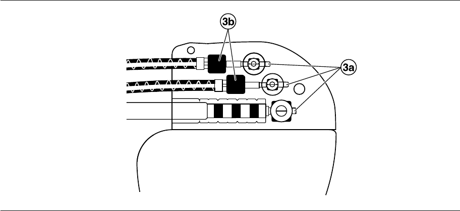
3. Confirm that the lead is fully inserted into the connector pin cavity by viewing the device connector block from
the side or end.
a. The lead connector pin should be clearly visible beyond the setscrew block (see Figure 2).
b. The lead connector ring should be completely inside the spring contact block. There is no setscrew in this
location (see Figure 2).
Figure 2. Confirming the lead connection
4. Tighten the setscrew by turning it clockwise until the torque wrench clicks. Remove the torque wrench.
5. Gently tug on the lead to confirm a secure fit. Do not pull on the lead until the setscrew has been tightened.
6. Repeat these steps for each lead.
4.5 Positioning and securing the device
Caution: Program AT/AF detection to Monitor to avoid inappropriate therapy delivery while closing the pocket.
Note: To optimize the ability of the device to connect to a wireless monitor, implant the device within 4 cm (1.6 in)
of the surface of the skin.
4.5.1 How to position and secure the device
1. Verify that each lead connector pin or pin plug is fully inserted into the connector port and that all setscrews
are tight.
2. To prevent twisting of the lead body, rotate the device to loosely wrap the excess lead length (see Figure 3).
Do not kink the lead body.
21
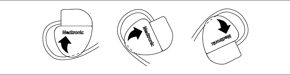
Figure 3. Rotating the device to wrap the leads
3. Place the device and the leads into the surgical pocket.
4. Use nonabsorbable sutures to secure the device within the pocket and minimize post-implant rotation and
migration. Use a surgical needle to penetrate the suture hole on the device.
5. Suture the pocket incision closed.
4.6 Completing the implant procedure
Warning: Do not program AT/AF Detection to On or enable automatic atrial ATP therapies until the atrial lead has
matured (approximately 1 month after implant). If the atrial lead dislodges and migrates to the ventricle, the device
could inappropriately detect AT/AF, deliver atrial ATP to the ventricle, and possibly induce a life-threatening
ventricular tachyarrhythmia.
4.6.1 How to complete programming the device
1. If unipolar leads are implanted, you may want to manually complete the Implant Detection process.
a. Select the Params icon.
b. Program the Pace Polarity and Sense Polarity parameters to Unipolar.
c. Select Additional Features… and program the Implant Detection parameter to Off/Complete.
2. Verify that the pacing, detection, and atrial ATP therapies parameters are programmed to values that are
appropriate for the patient.
3. Enter the patient’s information.
Note: Be sure to use the Patient Information screen to enter complete information about the implanted leads.
Be sure to use the MRI SureScan System/Other Hardware screen to enter complete information about other
hardware implanted in the patient, including abandoned devices or leads, and lead extenders or adaptors.
This information will be used in the future if the patient needs to be evaluated for an MRI scan. For more
information, see the programming guide.
4. Program the Medtronic CareAlert parameters, if applicable.
5. Program the Data Collection Setup parameters.
4.6.2 How to assess the performance of the device and leads
After implanting the device, x-ray the patient as soon as possible to verify device and lead placement. Before the
patient is discharged from the hospital, assess the performance of the implanted device and leads.
1. Monitor the patient’s electrocardiogram until the patient is discharged. If a lead dislodges, it usually occurs
during the immediate postoperative period.
2. Check the pacing and sensing values, and adjust the values if necessary. Verify the safety margin for the
pacing threshold.
3. Interrogate the device, and print a Final Report to document the postoperative programmed device status.
22
4.7 Replacing a device
To retain the ability to safely scan the SureScan pacing system during MRI scans, the MRI conditions for use in
Section 1.5, “MRI conditions for use”, page 6 must be followed. Refer to the Medtronic MRI technical manual for
additional information.
Warning: Bipolar or unipolar atrial and right ventricular leads may be used with the
Percepta Quad CRT-P MRI SureScan Model W4TR01 device, but if leads other than bipolar MRI SureScan leads
are used, the system is contraindicated for MRI scans. The left ventricular lead must be a quadripolar lead, but if
it is not a quadripolar MRI SureScan lead, the system is contraindicated for MRI scans. Before performing an MRI
scan, refer to the MRI technical manual for additional information.
Warning: Abandoned leads or previously implanted non-MRI labeled leads compromise the ability to safely scan
the SureScan pacing system during future MRI scans. When implanting a SureScan pacing system, consider the
risks associated with removing previously implanted leads before removing the leads to maintain the ability to
safely scan the SureScan pacing system. Refer to the Medtronic MRI technical manual for additional information.
Warning: Keep external pacing equipment nearby for immediate use. The patient does not receive pacing therapy
from the device when the lead is disconnected, or when the device is removed from the pocket while the device
is operating in unipolar pacing mode.
Caution: Disable tachyarrhythmia detection to avoid inappropriate therapy delivery while explanting the device.
Caution: Unipolar atrial leads may be used with the device, but bipolar atrial leads are recommended. If unipolar
atrial leads are used, AT/AF Detection must be programmed to Monitor and the Capture Management feature must
be programmed to Off.
Note: To meet the implant requirements, you may need to reposition or replace the chronic leads. For more
information, see Section 4.2, “Selecting and implanting the leads”, page 18.
Note: Any unused leads that remain implanted must be capped with a lead pin cap to avoid transmitting electrical
signals. Contact your Medtronic representative for information about lead pin caps. Any capped or unused leads
are considered abandoned leads in the MRI conditions for use, and their presence will contraindicate the system
for MRI scanning.
4.7.1 How to explant and replace a device
1. Program the device to a mode that is not rate-responsive to avoid potential rate increases while explanting the
device.
2. Dissect the leads and the device free from the surgical pocket. Do not nick or breach the lead insulation.
3. Use a torque wrench to loosen the setscrews in the connector block.
4. Gently pull the leads out of the connector ports.
5. Evaluate the condition of each lead (see Section 4.3, “Testing the lead system”, page 19). Replace a lead if
the electrical integrity is not acceptable or if the lead connector pin is pitted or corroded. If you explant the lead,
return the lead to Medtronic for analysis and disposal.
6. Connect the leads to the replacement device (see Section 4.4, “Connecting the leads to the device”,
page 20).
Note: Lead adaptors may be needed to connect the leads to the replacement device. Contact a Medtronic
representative for information about compatible lead adaptors.
Note: Lead adaptors compromise the ability to safely perform an MRI scan on the SureScan pacing system
in the future. Patients with lead adaptors are contraindicated for an MRI scan.
7. Position and secure the device in the surgical pocket, and suture the pocket incision closed (see Section 4.5,
“Positioning and securing the device”, page 21).
8. Contact Medtronic for Return Mailer Kits to return explanted devices for analysis and disposal. See the back
cover for addresses. Note: Disposal of explanted devices or leads is subject to local, state, and federal
regulations.
23
5 Product specifications
5.1 Physical characteristics
Table 3. Physical characteristics
Volumea20.5 cm3
Mass 30 g
H x W x Db59 mm x 46.5 mm x 11 mm
Radiopaque IDcRNP
Medtronic identifier
Surface area of titanium device can 40.7 cm2
Materials in contact with human tissuedTitanium, polyurethane, silicone rubber
Battery Lithium-hybrid CFx silver vanadium oxide
aVolume with connector holes unplugged.
bGrommets may protrude slightly beyond the can surface.
cThe radiopaque ID, which includes a Medtronic-identifier symbol, can be viewed in a fluoroscopic image of the
device.
dThese materials have been successfully tested for the ability to avoid biological incompatibility. The device does
not produce an injurious temperature in the surrounding tissue during normal operation.
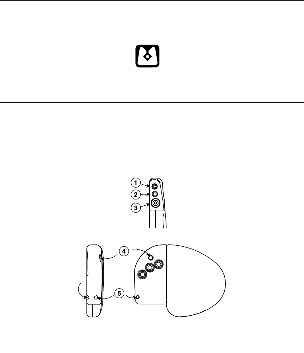
Figure 4. Connector and suture holes
1 IS-1 connector port, A
2 IS-1 connector port, RV
3 IS4 connector port, LV
4 Suture hole
5 Suture hole
24
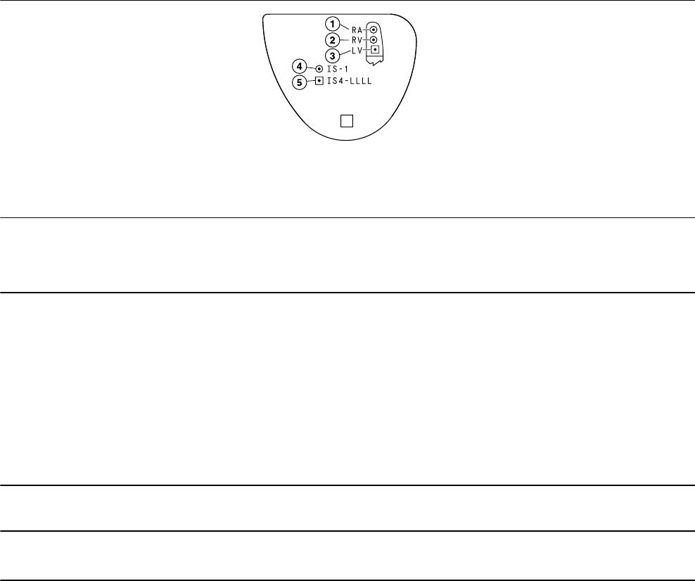
The Model W4TR01 shield graphics are shown in Figure 5.
The IS-1 marking in Figure 5 indicates that the A and RV lead connectors conform to ISO 5841-3.
The IS4-LLLL marking in Figure 5 indicates that the LV lead connector conforms to ISO 27186.
Figure 5. Shield graphics: Model W4TR01
1 RA = right atrial
2 RV = right ventricular
3 LV = left ventricular
4 IS-1 marking
5 IS4-LLLL marking
5.2 Electrical specifications
Table 4. Battery characteristics
Manufacturer Medtronic Energy and Component Center
Model Delta 26H3
Number of battery cells 1
Chemistry Lithium-hybrid CFx silver vanadium oxide
Nominal voltage 3.25 V
Mean usable capacity 1.19 Ah
Mean capacity to RRT 1.03 Ah
Residual usable capacity at RRT 0.16 Ah
Table 5. Current consumption
Current consumption (at 100% pacing)a12.77 µA
Current consumption (at 100% inhibition)b7.14 µA
aCurrent consumption when pacing into 500 Ω ±1% loads at the Beginning of Service in DDDR mode at 60 bpm,
2.5 V, 0.4 ms.
bCurrent consumption when at the Beginning of Service in DDDR mode at 60 bpm, 2.5 V, 0.4 ms, 500 Ω ±1%.
25

5.2.1 Output waveforms
Figure 6. Output waveform at nominal conditions (resistive load: 500 Ω)
5.2.2 Variation with temperature
Basic rate, test pulse rate, pulse duration, and pulse amplitude remain within expected tolerances when the device
temperature is between 17°C and 45°C (63°F to 113°F). Sensitivity at nominal conditions as measured at 37°C
(98.6°F) can vary as much as ±1% per °C from 17°C to 45°C (63°F to 113°F).
5.3 Replacement indicators
The battery voltage and messages about replacement status appear on the programmer display and on printed
reports. The Recommended Replacement Time (RRT), Elective Replacement Indicator (ERI), and the End of
Service (EOS) conditions are listed in Table 6.
Table 6. Replacement indicators
Recommended Replacement Time (RRT) 180 days after 3 consecutive daily automatic meas-
urements of ≤ 2.63 V or immediately after 3 consec-
utive daily automatic measurements of ≤ 2.60 V,
whichever comes first
Elective Replacement Indicator (ERI) 3 months after RRT
End of Service (EOS) 3 months after ERI
RRT date – The programmer displays the date when the battery reached RRT on the Quick Look II and Battery and
Lead Measurements screens.
Replace at EOS – If the programmer indicates that the device is at EOS, replace the device immediately.
RRT operation – When the device reaches RRT, it continues to operate with its programmed parameters.
However, placing a magnet over the device initiates asynchronous pacing at 65 bpm rather than at 85 bpm.
ERI operation – When the device reaches ERI, it automatically changes the value of several parameters as shown
in Table 7.
Table 7. Parameter settings after ERI
Pacing Mode VVI
Lower Rate 65 bpm
V. Pacing as programmed
26

Table 7. Parameter settings after ERI (continued)
RV Amplitude, LV Amplitude as programmed
RV Pulse Width, LV Pulse Width as programmed
Sleep Off
V. Rate Stabilization Off
AT/AF Detection Monitora
Pre-arrhythmia EGM Offb
Multiple point pacing (MPP) Off
aWhen AT/AF Detection is set to Monitor, AT/AF therapies are not available.
bPre-arrhythmia EGM cannot be reprogrammed after ERI.
Notes:
●After ERI, all pacing parameters can be programmed, including mode and rate. Reprogramming the pacing
parameters may reduce the duration of the ERI to EOS period.
●When the MRI SureScan mode is programmed to On, battery measurements are taken, but the device does
not report RRT, EOS, or ERI until the MRI SureScan mode has been programmed to Off.
Prolonged Service Period – The Prolonged Service Period (PSP) is the time between the RRT and EOS. The
PSP is defined as 6 months assuming the following conditions, in conformance with ISO 14708: 100% DDD pacing
at 60 bpm, 2.5 V atrial, RV, and LV pacing amplitudes; 0.4 ms pulse width; and 600 Ω pacing load. The EOS may
be indicated before the end of 6 months if the device exceeds these conditions.
5.4 Projected service life
The projected service life estimates in Table 8 and Table 9 are based on DDD mode pacing, with pacing amplitudes
programmed to the specified values, pulse width values of 0.4 ms, and a 60 bpm pacing rate.
The projected service life estimates in Table 10 are based on the pacing characteristics stated in the table.
All of the projected service life estimates are based on the following assumptions:
●Pre-arrhythmia EGM storage programmed to On for the lifetime of the device
●EGM Source parameters set to nominal values
●A quarterly schedule of Medtronic patient monitor transmissions
●Typical shelf storage time before implant
Projected service life estimates are based on accelerated battery discharge data and device modeling as
specified. These values should not be interpreted as precise numbers.
Table 8. Projected service life in years, with the AdaptivCRT feature programmed to Adaptive Bi-V or Nonadaptive
CRT
Percent pacing 500 Ω pacing impedance 600 Ω pacing impedance
Atrial % RV % LV % 2.5 V 3.5 V 2.5 V 3.5 V
0% 100% 100% 10.1 7.7 10.6 8.2
15% 100% 100% 9.9 7.4 10.4 8.0
50% 100% 100% 9.4 6.8 9.9 7.4
100% 100% 100% 8.7 6.1 9.3 6.8
27

Table 9. Projected service life in years, with the AdaptivCRT feature programmed to Adaptive Bi-V and LV
Percent pacing 500 Ω pacing impedance 600 Ω pacing impedance
Atrial % RV % LV % 2.5 V 3.5 V 2.5 V 3.5 V
0% 50% 100% 10.8 8.6 11.2 9.1
15% 50% 100% 10.5 8.2 11.0 8.8
50% 50% 100% 9.9 7.5 10.4 8.1
100% 50% 100% 9.2 6.7 9.7 7.3
Table 10. Projected service life in years per conditions specified in EN 45502-2-1 and ISO 14708-2
Standard conditionsa2.5 V 5.0 V
EN 45502-2-1
●100% DDDR pacing
●500 Ω ±1% pacing impedance
●70 bpm
●0.4 ms
7.4 2.8
ISO 14708-2
●100% DDDR pacing
●600 Ω ±1% pacing impedance
●60 bpm
●0.4 ms
9.3 4.2
aData storage and diagnostic functions applicable to the pacing mode are On.
5.4.1 Projected service life considerations
Shelf storage time – These projections are based on typical shelf storage time (5 months). Assuming worst-case
shelf storage time (18 months), longevity is reduced by an additional 6.4%.
Pre-arrhythmia EGM storage – These projections assume that Pre-arrhythmia EGM storage is programmed to
On for the lifetime of the device. Programming Pre-arrhythmia EGM storage to Off increases the projected service
life of the device by approximately 3.2% or 12 days per year.
Capture Management – The Capture Management feature can independently adapt each pacing amplitude
value. An Atrial Amplitude of 1.5 V, an RV Amplitude of 2.0 V, and an LV Amplitude of 2.5 V represent typical values
when using the Capture Management feature. At these settings, and with 100% atrial and biventricular pacing (at
60 bpm, 0.4 ms, and 600 Ω), the projected service life of the device is 10.6 years.
Medtronic patient monitor remote transmissions – Additional Medtronic patient monitor remote
transmissions reduce projected service life. For example, with 4 remote transmissions per year, and with 100%
atrial and biventricular pacing (at 60 bpm, 2.5 V, 0.4 ms, and 600 Ω), the projected service life of the device is 9.3
years. Projected service life reductions for more frequent remote transmission rates are as follows:
●Monthly transmissions over the life of the device reduce projected service life by 10 days, or 0.3%.
●Weekly transmissions over the life of the device reduce projected service life by 59 days, or 1.7%.
●Daily transmissions over the life of the device reduce projected service life by 394 days, or 11.5%
Multiple point pacing (MPP) – It is not recommended to use multiple point pacing unless there is evidence that
the patient is not responding to single site LV pacing (e.g., patient symptoms, quality of life, NYHA classification,
electrocardiographic and/or echocardiographic evidence based on clinician judgment). Long-term use of multiple
point pacing affects device longevity (14% median longevity reduction).
28

6 Device parameters
6.1 Emergency settings
Table 11. Emergency VVI settings
Parameter Selectable values
Pacing Mode VVI
Lower Rate 70 bpm
RV Amplitudea6 V
RV Pulse Widtha1.5 ms
RV Pace Polarity Unipolar
V. Pacing RV
V. Blank Post VP 240 ms
V. Rate Stabilization Off
V. Sense Response Off
aIf the programmed RV Amplitude is 8 V, VVI pacing is delivered at 8 V with a pulse width of 1.2 ms.
6.2 Magnet application
When a magnet is placed near the device, the pacing mode changes from the programmed mode to DOO, VOO,
or AOO, and the pacing rate changes to 100 bpm for 5 beats and then changes to 85 bpm or 65 bpm, as described
at the end of this section. Placing a magnet near the device suspends tachyarrhythmia detection. When the
magnet is removed, the device returns to its programmed operation.
Note: Magnet operation does not occur if telemetry between the device and programmer is established or if the
MRI SureScan mode is programmed to On.
The pacing mode will be DOO when the programmed pacing mode is a dual chamber mode or an MVP mode
(AAIR<=>DDDR, AAI<=>DDD), VOO when the programmed pacing mode is a single chamber ventricular mode,
and AOO when the programmed pacing mode is a single chamber atrial mode.
The pacing rate will be 85 bpm if the device conditions are normal and it will be 65 bpm if a Recommended
Replacement Time (RRT) indicator or a device reset has occurred.
6.3 Tachyarrhythmia detection parameters
Table 12. Tachyarrhythmia detection parameters
Parameter Programmable values Shipped Reset
AT/AF Detection On; Monitor Monitor Monitor
Zones 1 ; 2 — —
AT/AF Interval (Rate)a150; 160 … 350 … 450 ms 350 ms 350 ms
Fast AT/AF Interval (Rate)a150; 160 … 200 … 250 ms 200 ms 200 ms
VT Monitor Monitor ; Off Monitor Off
VT Monitor Interval (Rate)a280; 290 … 400 … 500 ms 400 ms 400 ms
29

Table 12. Tachyarrhythmia detection parameters (continued)
Parameter Programmable values Shipped Reset
RV Sensitivityb0.45; 0.60; 0.90; 1.20; 2.00; 2.80;
4.00; 5.60; 8.00; 11.30 mV
Bipolar: 0.9 mV
Unipolar: 2.80 mV
0.9 mV 2.8 mV
Atrial Sensitivityc0.15; 0.30; 0.45; 0.60; 0.90; 1.20;
1.50; 1.80; 2.10; 4.0 mV; Off
Bipolar: 0.3 mV
Unipolar: 0.45 mV
0.3 mV 0.45 mV
aThe measured intervals are truncated to a 10 ms multiple (for example, 457 ms becomes 450 ms). The device
uses this truncated interval value when applying the programmed criteria and calculating interval averages.
bThe device complies with the requirements of ISO 14708-2 when the sensitivity threshold is programmed to
2.0 mV or higher.
cThe device complies with the requirements of ISO 14708-2 when the sensitivity threshold is programmed to
1.8 mV or higher.
6.4 Atrial tachyarrhythmia therapy parameters
Table 13. Atrial tachyarrhythmia therapy parameters
Parameter Programmable values Shipped Reset
Anti-Tachy Pacing (ATP)
Fast AT/AF Rx Status On; Off Off Off
Therapy Type Ramp; Burst+
Rx1: Ramp
Rx2: Burst+
Rx3: Ramp
— —
AT/AF Rx Status On; Off Off Off
Therapy Type Ramp; Burst+
Rx1: Ramp
Rx2: Burst+
Rx3: Ramp
— —
Burst+ parameters
Initial # S1 Pulses 1; 2; 3 … 11 … 15; 20; 25 — —
A-S1 Interval (%AA) 28; 31; 34; 38; 41 … 59; 63; 66; 69 … 84 ; 88;
91; 94; 97%
S1-S2 (%AA) 28; 31; 34; 38; 41 … 59; 63; 66; 69 … 81 ; 84;
88; 91; 94; 97%; Off
— —
S2-S3 Decrement 0; 10; 20 … 80 ms; Off — —
Interval Decrement 0; 10 ; 20; 30; 40 ms — —
# Sequences 1; 2; 3 … 10 — —
30

Table 13. Atrial tachyarrhythmia therapy parameters (continued)
Parameter Programmable values Shipped Reset
Ramp parameters
Initial # S1 Pulses 1; 2; 3 … 13 ; 14; 15; 20; 25 — —
A-S1 Interval (%AA)
Rx1 28; 31; 34; 38; 41 … 59; 63; 66 … 84; 88;
91 ; 94; 97%
— —
Rx2 28; 31; 34; 38; 41 … 59; 63; 66 … 84; 88;
91 ; 94; 97%
— —
Rx3 28; 31; 34; 38; 41 … 59; 63; 66 … 81 ; 84; 88;
91; 94; 97%
— —
Interval Decrement 0; 10 … 40 ms — —
# Sequences 1; 2 … 8; 9; 10 — —
Stop Atrial Rx After (shared)
Rx/Lead Suspect…
Disable Atrial ATP if it
accelerates V. rate?
Yes ; No Yes Yes
Disable all atrial therapies
if atrial lead position is
suspect? (Atrial Lead
Position Check)
Yes ; No Yes No
Duration to Stop 12; 24; 48 ; 72 hr;
None
48 hr 48 hr
Episode Duration Before Rx Delivery
Episode Duration Before
ATP
0; 1 ; 2 … 5; 7; 10; 15; 20; 25; 30; 40; 50 min;
1; 2; 3; 4; 5; 6; 12; 24 hr
1 min 1 min
Reactive ATP
Rhythm Change On ; Off On On
Time Interval Off ; 2; 4; 7; 12; 24; 36; 48 hr Off Off
Shared A. ATP
A-A Minimum ATP Intervala100; 110; … 150 … 400 ms 150 ms 150 ms
A. Pacing Amplitude 1; 2; 3 …6 ; 8 V 6 V 6 V
A. Pacing Pulse Width 0.1; 0.2 … 1.5 ms 1.5 ms 1.5 ms
VVI Backup Pacing Off; On (Always); On (Auto-Enable) On (Auto-
Enable)
On (Auto-
Enable)
VVI Backup Pacing Rate 60; 70 … 120 bpm 70 bpm 70 bpm
aThe measured intervals are truncated to a 10 ms multiple (for example, 457 ms becomes 450 ms). The device
uses this truncated interval value when applying the programmed criteria and calculating interval averages.
31
6.5 Pacing parameters
Table 14. Modes, rates, and intervals
Parameter Programmable values Shipped Reset
Mode DDDR; DDD ; AAIR<=>DDDR;
AAI<=>DDD; DDIR; DDI; AAIR; AAI;
VVIR; VVI; DOO; AOO; VOO; ODO
DDD VVI
Mode Switch On ; Off On Off
Lower Ratea30; 35 … 50 ; 70; 75 … 150 bpm 50 bpm
(1000 ms)
65 bpm
(920 ms)
Upper Tracking Rate 80; 85 … 130 …175 bpm; 180; 190 …
210 bpm
130 bpm 120 bpm
Paced AVb30; 40 … 130 … 350 ms 130 ms 180 ms
Sensed AVb30; 40 … 100 … 350 ms 100 ms 150 ms
Maximum AV Interval limit Off ; 250; 260 … 500 ms Off Off
PVARP Auto ; 150; 160 … 500 ms Auto Auto
Minimum PVARP 150; 160 … 250 … 500 ms 250 ms 250 ms
A. Refractory Period 150; 160 … 310 … 500 ms 310 ms 310 ms
aThe corresponding Lower Rate interval can be calculated as follows: Lower Rate interval (ms) = 60,000/Lower
Rate.
bIf CRT is adaptive, Paced AV and Sensed AV cannot be selected or programmed.
Table 15. Atrial parameters
Parameter Programmable values Shipped Reset
Atrial Amplitude 0.5; 0.75 … 3.5 … 5; 5.5; 6; 8 Va3.5 V —
Atrial Pulse Width 0.03; 0.06; 0.1; 0.2; 0.3; 0.4 … 1.5 ms 0.4 ms —
Atrial Sensitivity Off; 0.15; 0.3; 0.45; 0.6; 0.9; 1.2; 1.5; 1.8;
2.1; 4.0 mV
Unipolar: 0.45 mV
Bipolar: 0.3 mV
0.3 mV 0.45 mV
Atrial Pace Polarity Bipolar; Unipolar Configureb—
Atrial Sense Polarity Bipolar; Unipolar ConfigurebUnipolar
Atrial Lead Monitor Monitor Only; Adaptive Monitor Only Monitor Only
Min Limit 200 ; 300; 400; 500 Ω 200 Ω 200 Ω
Max Limit 1000; 1500; 2000; 3000 Ω 3000 Ω 3000 Ω
aWhen Atrial Amplitude is 8 V, Atrial Pulse Width must be less than 1.3 ms.
b“Configure” is displayed when the device is automatically configuring the lead polarity at implant. It is not a
selectable value.
32

Table 16. RV parameters
Parameter Programmable values Shipped Reset
RV Amplitude 0.5; 0.75 … 3.5 … 5; 5.5; 6; 8 Va3.5 V 6 V
RV Pulse Width 0.03; 0.06; 0.1; 0.2; 0.3; 0.4 … 1.5 ms 0.4 ms 1.5 ms
RV Sensitivity 0.45; 0.60; 0.90; 1.20; 2.00; 2.80; 4.00;
5.60; 8.00; 11.30 mV
Unipolar: 2.80 mV
Bipolar: 0.90 mV
0.90 mV 2.80 mV
RV Pace Polarity Bipolar; Unipolar ConfigurebUnipolar
RV Sense Polarity Bipolar; Unipolar ConfigurebUnipolar
RV Lead Monitor Monitor Only; Adaptive Monitor Only Monitor Only
Min Limit 200 ; 300; 400; 500 Ω 200 Ω 200 Ω
Max Limit 1000; 1500; 2000; 3000 Ω 3000 Ω 3000 Ω
aWhen RV Amplitude is 8 V, RV Pulse Width must be less than 1.3 ms.
b“Configure” is displayed when the device is automatically configuring the lead polarity at implant. It is not a
selectable value.
Table 17. LV parameters
Parameter Programmable values Shipped Reset
LV Amplitude 0.5; 0.75 … 3.5 … 5; 5.5; 6; 8 Va3.5 V —
LV Pulse Width 0.03; 0.06; 0.1; 0.2; 0.3; 0.4 … 1.5 ms 0.4 ms 1.5 ms
LV Pace Polarity LV1 to LV2; LV1 to LV3; LV1 to LV4; LV1 to
Can; LV2 to LV1; LV2 to LV3; LV2 to LV4;
LV2 to Can; LV3 to LV1; LV3 to LV2; LV3 to
LV4; LV3 to Can; LV4 to LV1; LV4 to LV2;
LV4 to LV3; LV4 to Can
LV1 to LV2 LVtip to Can
LV Lead Monitor Monitor Only; Adaptive Monitor Only Monitor Only
Min Limit 200 ; 300; 400; 500 Ω 200 Ω 200 Ω
Max Limit 800; 1000; 1500; 2000; 3000 Ω 3000 Ω 3000 Ω
aWhen LV Amplitude is 8 V, LV Pulse Width must be less than 1.3 ms.
Table 18. 2nd LV parameters
Parameter Programmable values Shipped Reset
2nd LV Amplitude 0.5; 0.75 … 3.5 … 5; 5.5; 6; 8 Va0 V 0 V
2nd LV Pulse Width 0.03; 0.06; 0.1; 0.2; 0.3; 0.4 … 1.5 ms 0.4 ms 0.4 ms
2nd LV Pace Polarity LV1 to LV2; LV1 to LV3; LV1 to LV4; LV1 to
Can; LV2 to LV1; LV2 to LV3; LV2 to LV4;
LV2 to Can; LV3 to LV1; LV3 to LV2; LV3 to
LV4; LV3 to Can; LV4 to LV1; LV4 to LV2;
LV4 to LV3; LV4 to Can
LV4 to Can LV4 to Can
aWhen 2nd LV Amplitude is 8 V, 2nd LV Pulse Width must be less than 1.3 ms.
33

Table 19. CRT/MPP pacing parameters
Parameter Programmable values Shipped Reset
AdaptivCRT Adaptive Bi-V and LV ; Adaptive Bi-V;
Nonadaptive CRT
Adaptive Bi-V
and LV
Nonadaptive
CRT
V. PacingaRV; RV→LV; LV→RV LV→RV RV
V-V Pace Delay Auto ; 0; 10 … 80 ms Auto 0 ms
EffectivCRT During AF On ; Off On Off
Maximum Rate 80; 85 …110 … 130 bpm 110 bpm —
MPP On; Off Off Off
LV-LV Pace Delay 0 ; 10 … 80 ms 0 ms 0 ms
V. Sense Response On ; Off On Off
Maximum Rate 95; 100 …130 … 150 bpm 130 bpm —
Atrial Tracking Recovery On ; Off On —
aIf CRT is adaptive, V. Pacing cannot be selected or programmed.
Table 20. Atrial Capture Management parameters
Parameter Programmable values Shipped Reset
Atrial Capture Management Adaptive ; Monitor; Off Adaptive Off
Atrial Amplitude Safety
Margin
1.5x; 2.0x ; 2.5x; 3.0x 2.0x 2.0x
Atrial Minimum Adapted
Amplitude
1.0; 1.5 ; 2.0; 2.5; 3.0; 3.5 V 1.5 V 1.5 V
Atrial Acute Phase Remain-
ing
Off; 30; 60; 90; 120 ; 150 days 120 days 120 days
Table 21. RV Capture Management parameters
Parameter Programmable values Shipped Reset
RV Capture Management Adaptive ; Monitor; Off Adaptive Off
RV Amplitude Safety Mar-
gin
1.5x; 2.0x ; 2.5x; 3.0x 2.0x 2.0x
RV Minimum Adapted
Amplitude
1.0; 1.5; 2.0 ; 2.5; 3.0; 3.5 V 2 V 2 V
RV Acute Phase Remaining Off; 30; 60; 90; 120 ; 150 days 120 days 120 days
Table 22. LV Capture Management parameters
Parameter Programmable values Shipped Reset
LV Capture Management Adaptive ; Monitor; Off Adaptive Off
LV Amplitude Safety Margin +Auto ; +0.5; +1.0; +1.5; +2.0; +2.5 V +Auto —
LV Maximum Adapted
Amplitude
0.5; 0.75 … 5.0; 5.5; 6 V 6.0 V 6.0 V
34
Table 23. 2nd LV Capture Management parameters
Parameter Programmable values Shipped Reset
2nd LV Capture Manage-
ment
Adaptive ; Monitor; Off — Off
2nd LV Amplitude Safety
Margin
+Auto ; +0.5; +1.0; +1.5; +2.0; +2.5 V — +Auto
2nd LV Maximum Adapted
Amplitude
0.5; 0.75 … 5.0; 5.5; 6 V — 6.0 V
Table 24. Blanking periods
Parameter Programmable values Shipped Reset
PVAB Interval 10a; 20 … 100; 110; 120 …150 … 300 ms 150 ms 150 ms
PVAB Method Partial ; Partial+; Absolute Partial Partial
A. Blank Post AP 150; 160 … 200 … 250 ms 200 ms 240 ms
A. Blank Post AS 100 ; 110 … 170 ms 100 ms 100 ms
V. Blank Post VP 150; 160 … 230 … 320 ms 230 ms 240 ms
V. Blank Post VS 120 ; 130 … 170; 200; 220; 250; 280; 300;
320 ms
120 ms 120 ms
aIf the PVAB Method is set to Partial, the minimum selectable value for the PVAB Interval is 100 ms
Table 25. Rate Response Pacing parameters
Parameter Programmable values Shipped Reset
Rates
ADL Rate 60; 65 … 95 … 170 bpm 95 bpm 95 bpm
Upper Sensor 80; 85 … 120 … 175 bpm 120 bpm 120 bpm
Rate Profile Optimization On ; Off On Off
Adjust Rate Response
ADL Response 1; 2; 3 ; 4; 5 3 3
Exertion Response 1; 2; 3 ; 4; 5 3 3
Additional Parameters…
Activity Threshold Low ; Medium Low; Medium High; High Low Medium Low
Activity Acceleration 15; 30 ; 60 s 30 s 30 s
Activity Deceleration Exercise ; 2.5; 5; 10 min Exercise 5 min
ADL Setpoint 5; 6 … 40; 42 … 80 18 18
UR Setpoint 15; 16 … 40; 42 … 80; 85 … 180 40 40
35

Table 26. Rate Adaptive AV parameters
Parameter Programmable values Shipped Reset
Rate Adaptive AVaOn ; Off On On
Start Rate 50; 55 … 90 … 145 bpm 90 bpm 60 bpm
Stop Rate 55; 60 … 130 … 175 bpm 130 bpm 120 bpm
Minimum Paced AV 30; 40 … 100 … 200 ms 100 ms 140 ms
Minimum Sensed AV 30; 40 … 70 … 200 ms 70 ms 110 ms
aIf CRT is adaptive, Rate Adaptive AV cannot be selected or programmed.
Table 27. Atrial Rate Stabilization parameters
Parameter Programmable values Shipped Reset
A. Rate Stabilization On; Off Off Off
Maximum Rate 80; 85 … 100 … 150 bpm 100 bpm 100 bpm
Interval Percentage Incre-
ment
12.5; 25 ; 50% 25% 25%
Table 28. Atrial Preference Pacing parameters
Parameter Programmable values Shipped Reset
A. Preference Pacing On; Off Off Off
Maximum Rate 80; 85 … 100 … 150 bpm 100 bpm 100 bpm
Interval Decrement 30 ; 40; 50 … 100; 150 ms 30 ms 50 ms
Search Beats 5; 10; 15; 20 … 25; 50 20 5
Table 29. Post Mode Switch Overdrive Pacing (PMOP) parameters
Parameter Programmable values Shipped Reset
Post Mode Switch On; Off Off Off
Overdrive Rate 70; 75; 80 … 120 bpm 80 bpm 65 bpm
Overdrive Duration 0.5; 1; 2; 3; 5 ; 10; 20; 30; 60; 90; 120 min 5 min 5 min
Table 30. Conducted AF Response parameters
Parameter Programmable values Shipped Reset
Conducted AF Response On ; Off On Off
Response Level Low; Medium ; High Medium Medium
Maximum Rate 80; 85 … 110 … 130 bpm 110 bpm 110 bpm
36

Table 31. Ventricular Rate Stabilization parameters
Parameter Programmable values Shipped Reset
V. Rate Stabilization On; Off Off Off
Maximum Rate 80; 85 … 100 …120 bpm 100 bpm 120 bpm
Interval Increment 100; 110 … 150 … 400 ms 150 ms 150 ms
Table 32. Rate Drop Response parameters
Parameter Programmable values Shipped Reset
Rate Drop ResponseaOn; Off Off Off
Detection Type Drop ; Low Rate; Both Drop Drop
Drop Detection
Drop Size 10; 15 … 25 … 50 bpm 25 bpm 25 bpm
Drop Rate 30; 40 … 60 … 100 bpm 60 bpm 60 bpm
Detection Window 10; 15; 20; 25; 30 s
1 ; 1.5; 2; 2.5 min
1 min 1 min
Low Rate Detection
Detection Beats 1; 2; 3 beats 3 beats 3 beats
Intervention
Intervention Rate 70; 75 … 100 … 150 bpm 100 bpm 100 bpm
Intervention Duration 1; 2 … 15 min 2 min 2 min
aWhen Rate Drop Response is set to On, the lower rate is automatically set to 45 bpm.
Table 33. Sleep parameters
Parameter Programmable values Shipped Reset
Sleep On; Off Off Off
Sleep Rate 30; 35 … 50 ; 55; 60; 70; 75 … 100 bpm 50 bpm 50 bpm
Bed Time 00:00; 00:10 … 22:00 … 23:50 22:00 22:00
Wake Time 00:00; 00:10 … 07:00 … 23:50 07:00 07:00
Table 34. Non-Competitive Atrial Pacing (NCAP) parameters
Parameter Programmable values Shipped Reset
Non-Comp Atrial Pacing On ; Off On On
NCAP Interval 200; 250; 300 ; 350; 400 ms 300 ms 300 ms
37

Table 35. MRI SureScan parameters
Parameter Programmable values Shipped Reset
MRI SureScan On; Off Off Off
MRI Pacing Mode DOO; AOO; VOO; ODO — —
MRI Pacing Rate 60; 70; 75; 80 … 120 bpm — —
Table 36. Additional pacing features
Parameter Programmable values Shipped Reset
PMT Intervention On ; Off On Off
PVC Response On ; Off On On
V. Safety PacingaOn ; Off On On
aDelivered as LV pacing when the AdaptivCRT operating value is LV. Delivered as RV pacing when RV only
pacing is permanently programmed. Otherwise, delivered as BiV pacing.
6.6 Data collection parameters
Table 37. Data collection parameters
Parameter Programmable values Shipped Reset
EGM 1 Source Can to Aring (LECG); Can to RVring; Atip to
Aring ; Atip to RVring; Atip to Can; Aring to
RVring; RVtip to RVring; RVtip to Can; Can
to LV4
Atip to Aring Atip to Aring
EGM 1 Range ±1; ±2; ±4; ±8 ; ±12; ±16; ±32 mV ±8 mV ±8 mV
EGM 2 Source Can to RVring; RVtip to RVring ; RVtip to
Can; LV1 to Can; LV1 to LV2; LV2 to Can
RVtip to RVring RVtip to RVring
EGM 2 Range ±1; ±2; ±4; ±8 ; ±12; ±16; ±32 mV ±8 mV ±8 mV
EGM 3 Source RVtip to RVring; Can to RVring; Atip to
RVring; Atip to Aring; Can to Aring
(LECG) ; LV1 to Can; LV1 to LV2; LV1 to
LV3; LV1 to LV4; LV2 to Can; LV2 to LV3; LV2
to LV4; LV3 to LV4; LV3 to Can; LV4 to Can
Can to Aring
(LECG)
Can to Aring
(LECG)
EGM 3 Range ±1; ±2; ±4; ±8 ; ±12; ±16; ±32 mV ±8 mV ±8 mV
Monitored EGM1 and EGM2 ; EGM1 and EGM3;
EGM2 and EGM3
EGM1 and EGM2 EGM1 and EGM2
Pre-arrhythmia
EGM
Off; On Continuous On Continuous Off
AT/AF Daily Burden 0.5; 1; 2; 6 ; 12; 24 hr/24hr 6 hr 6 hr
Avg. V. Rate During
AT/AF Burden
0.5; 1; 2; 6 ; 12; 24 hr/24hr 6 hr 6 hr
Avg. V. Rate During
AT/AF V. Rate
90; 100 …130; 140; 150 bpm 100 bpm 100 bpm
OptiVol Thresholda30; 40; 50; 60 …160; 170; 180 60 60
38

Table 37. Data collection parameters (continued)
Parameter Programmable values Shipped Reset
V. Sensing Episodes…
Consecutive VS to
detect >=
5; 8; 10 ; 15; 20; 30; 40; 50; 100; 150; 200 10 senses 10 senses
Consecutive VP to
terminate >=
2; 3 ; 5; 10 3 paces 3 paces
Device Date/Timeb(select Time Zone) — —
Holter Telemetry Off ; 0.5; 1; 2; 4; 8; 16; 24; 36; 46 hr Off Off
Wireless Telemetry
with Monitor
On; Off On Onc
aDecreasing the OptiVol Threshold will make the device more sensitive to changes in the patient’s thoracic fluid
status. Increasing the OptiVol Threshold could delay or prevent device observation of significant changes in the
patient’s thoracic fluid status.
bThe times and dates stored in episode records and other data are determined by the Device Date/Time clock.
cThe reset value may be set to Off if there is an issue with wireless communication that requires it to be disabled.
6.7 Medtronic CareAlert parameters
Table 38. Clinical Management Alerts
Parameter Programmable values Shipped Reset
AT/AF Burden and Rate Settings…
AT/AF Alerts
AT/AF Daily Burden Enable Off ; On Off Off
Daily AT/AF Burden 0.5; 1; 2; 6 ; 12; 24 hr/24hr 6 hr 6 hr
Avg. V. Rate During AT/AF Ena-
ble
Off ; On Off Off
Daily Burden for Avg. V. Rate 0.5; 1; 2; 6 ; 12; 24 hr/24hr 6 hr 6 hr
Avg. V. Rate During AT/AF 90; 100 … 150 bpm 100 bpm 100 bpm
Monitored VT Episode Detec-
ted
Off ; On Off Off
Total VP < 90% Off ; OnaOff Off
OptiVol 2.0 Fluid Settings… Off Off Off
Observation Conditions
OptiVol Thresholdb30; 40; 50; 60 … 100; 120 …
180
60 60
aAlert triggered if percent of cumulative ventricular pacing is less than 90% for 7 consecutive days.
bDecreasing the OptiVol Threshold makes the device more sensitive to changes in the patient’s thoracic fluid
status. Increasing the OptiVol Threshold could delay or prevent device observation of significant changes in the
patient’s thoracic fluid status.
39

Table 39. Lead/Device Integrity Alerts
Parameter Programmable values Shipped Reset
Low Battery Voltage RRT On ; Off On Off
Lead Impedance Out of Range…
Lead Impedance
A. Pacing Enable On ; Off On Off
A. Pacing Less than 200 ; 300; 400; 500 Ω 200 Ω 200 Ω
A. Pacing Greater than 1000; 1500; 2000; 3000 Ω 3000 Ω 3000 Ω
RV Pacing Enable On ; Off On Off
RV Pacing Less than 200 ; 300; 400; 500 Ω 200 Ω 200 Ω
RV Pacing Greater than 1000; 1500; 2000; 3000 Ω 3000 Ω 3000 Ω
LV Pacing Enable On ; Off On Off
LV Pacing Less than 200 ; 300; 400; 500 Ω 200 Ω 200 Ω
LV Pacing Greater than 800; 1000; 1500; 2000; 3000 Ω 3000 Ω 3000 Ω
2nd LV Pacing Enable Off ; On Off Off
2nd LV Pacing Less than 200 ; 300; 400; 500 Ω 200 Ω 200 Ω
2nd LV Pacing Greater than 800; 1000; 1500; 2000; 3000 Ω 3000 Ω 3000 Ω
Capture Management High Threshold
High Threshold
A. Capture EnableaOff ; On Off Off
RV Capture EnablebOff ; On Off Off
LV Capture EnablecOff ; On Off Off
2nd LV Capture EnabledOff ; On Off Off
aIf programmed to On, alert notification is sent if A. capture management has measured high thresholds for 3
consecutive days.
bIf programmed to On, alert notification is sent if RV capture management has measured high thresholds for 3
consecutive days.
cIf programmed to On, alert notification is sent if LV capture management has measured a high threshold for one
day.
dIf programmed to On, alert notification is sent if 2nd LV capture management has measured a high threshold for
one day.
6.8 System test parameters
Table 40. System test parameters
Parameter Selectable values
Sensing test parameters
ModeaAAI; DDD; VVI; ODO
AV Delay 30; 40 … 350 ms
Lower Rateb30; 35 … 60; 70; 75 … 120 bpm
40

Table 40. System test parameters (continued)
Parameter Selectable values
Pacing Threshold test parameters
Test Type Amplitude; Pulse Width
Chamber Atrium; RV; LV
Decrement after 2; 3 … 15 pulses
Pace Polarity (Atrium, RV) Unipolar; Bipolar
Pace Polarity (LV) LV1 to LV2; LV1 to LV3; LV1 to LV4; LV1 to Can; LV2 to LV1;
LV2 to LV3; LV2 to LV4; LV2 to Can; LV3 to LV1; LV3 to LV2;
LV3 to LV4; LV3 to Can; LV4 to LV1; LV4 to LV2; LV4 to LV3;
LV4 to Can
Modea (RV or LV test) VVI; VOO; DDI; DDD; DOO
Modea (Atrium test) AAI; AOO; DDI; DDD; DOO
Lower Rateb30; 35 … 60; 70; 75 … 125 bpm
AV Delay 30; 40 … 350 ms
RV Amplitude 0.25; 0.5 … 5; 5.5; 6; 8 V
RV Pulse Width 0.03; 0.06; 0.1; 0.2 … 1.5 ms
LV Amplitude 0.25; 0.5 … 5; 5.5; 6; 8 V
LV Pulse Width 0.03; 0.06; 0.1; 0.2 … 1.5 ms
A. Amplitude 0.25; 0.5 … 5; 5.5; 6; 8 V
A. Pulse Width 0.03; 0.06; 0.1; 0.2 … 1.5 ms
V. Pace Blanking 150; 160 … 320 ms
A. Pace Blanking 150; 160 … 250 ms
PVARP 150; 160 … 500 ms
VectorExpress LV Automated test parameters
Pulse Width 0.40; 0.50 … 1.50 ms
Test LV1, 2, 3, 4 to Can; LV1 to LV2, LV3, LV4; LV2 to LV1, LV3,
LV4; LV3 to LV1, LV2, LV4; LV4 to LV1, LV2, LV3
CardioSync Optimization test parameters
Sensing Lower Rate 30; 35 … 60; 70; 75 … 90 bpm
Pacing Lower Rate 35; 40 … 60; 70; 75 … 95 bpm
aThe selectable values for this parameter depend on the programmed pacing mode.
bWhen performing the test in DDD mode, the Lower Rate must be less than the programmed Upper Tracking
Rate.
41

6.9 EP study parameters
Table 41. 50 Hz Burst induction parameters
Parameter Selectable values
Resume at Burst Enabled ; Disabled
Amplitude 1; 2; 3; 4 ; 5; 6; 8 Va
Pulse Width 0.10; 0.20 … 0.50 … 1.50 msb
VOO Backup (for atrial 50 Hz Burst)cOn; Off
Pacing Rate 60; 70 … 120 bpm
V. Amplituded,e 0.50; 0.75 … 5.00; 5.50; 6.00; 8.00 V
V. Pulse Widthd0.10; 0.20 … 1.50 ms
aAmplitude accuracy: ≤ 2.5 V (+0.50 V/-33%), > 2.5 V to ≤ 6.0 V (+20%/-33%), ≥ 6.0 V (+20%/-55%) to ERI; ≥
6.0 V (+20%/-65%) at ERI; > 2.5 V (+20%/-70%) at ERI for MPP mode only.
bPulse width accuracy: +3/-3 ms at 37°C.
cV. Backup Pacing is delivered to the RV chamber.
dThe default value for this parameter is set according to the permanently programmed settings for bradycardia
pacing.
eCrosstalk may occur when atrial pacing amplitude is greater than 6.0 V.
Table 42. Fixed Burst induction parameters
Parameter Selectable values
Resume at Burst Enabled ; Disabled
ChamberaAtrium; RV; RV+LV; LV
Interval 100; 110 … 600 ms
Amplitudeb1; 2; 3; 4 ; 5; 6; 8 V
Pulse Widthb0.10; 0.20 … 0.50 … 1.50 ms
VVI Backup (for atrial Fixed Burst)cOn; Off
Pacing Rate 60; 70 … 120 bpm
V. Amplituded,e 0.50; 0.75 … 5.00; 5.50; 6.00; 8.00 V
V. Pulse Widthd0.10; 0.20 … 1.50 ms
aIf the chamber selected is RV+LV, the delay is set to 2.5 ms with LV pace delivered first.
bApplies to all ventricular chambers paced.
cV. Backup Pacing is delivered to the RV chamber.
dThe default value for this parameter is set according to the permanently programmed settings for bradycardia
pacing.
eCrosstalk may occur when atrial pacing amplitude is greater than 6.0 V.
Table 43. PES induction parameters
Parameter Selectable values
Resume at Deliver Enabled ; Disabled
ChamberaAtrium; RV; RV+LV; LV
#S1 1; 2 … 8 … 15
42

Table 43. PES induction parameters (continued)
Parameter Selectable values
S1S1 100; 110 … 600 … 2000 ms
S1S2 Off; 100; 110 … 400 … 600 ms
S2S3 Off ; 100; 110 … 600 ms
S3S4 Off ; 100; 110 … 600 ms
Amplitudeb1; 2; 3; 4 ; 5; 6; 8 V
Pulse Widthb0.10; 0.20 … 0.50 … 1.50 ms
VVI Backup (for atrial PES)cOn; Off
Pacing Rate 60; 70 … 120 bpm
V. Amplituded,e 0.50; 0.75 … 5.00; 5.50; 6.00; 8.00 V
V. Pulse Widthd0.10; 0.20 … 1.50 ms
aIf the chamber selected is RV+LV, the delay is set to 2.5 ms with LV pace delivered first.
bApplies to all ventricular chambers paced.
cV. Backup Pacing is delivered to the RV chamber.
dThe default value for this parameter is set according to the permanently programmed settings for bradycardia
pacing.
eCrosstalk may occur when atrial pacing amplitude is greater than 6.0 V.
Table 44. Shared manual ATP therapy parameters
Parameter Selectable values
Minimum Interval (atrial ATP) 100; 110; 120; 130 … 400 ms
Minimum Interval (ventricular ATP) 150; 160 … 200 … 400 ms
Amplitudea1; 2 … 6 ; 8 V
Pulse Widtha0.10; 0.20 … 1.50 ms
VVI Backup (for atrial ATP therapy)bOn; Off
Pacing Rate 60; 70 … 120 bpm
V. Amplitudec,d 0.50; 0.75 … 5.00; 5.50; 6.00; 8.00 V
V. Pulse Widthc0.10; 0.20 … 1.50 ms
aApplies to all ventricular chambers paced.
bV. Backup Pacing is delivered to the RV chamber.
cThe default value for this parameter is set according to the permanently programmed settings for bradycardia
pacing.
dCrosstalk may occur when atrial pacing amplitude is greater than 6.0 V.
Table 45. Manual Ramp therapy parameters
Parameter Selectable values
ChamberaAtrium; RV; RV+LV; LV
Ventricular Ramp therapy parameters
#Pulses 1; 2 … 6 … 15
%RR Interval 50; 53; 56; 59; 63; 66 … 84; 88; 91; 94; 97 %
43

Table 45. Manual Ramp therapy parameters (continued)
Parameter Selectable values
Dec/Pulse 0; 10 ; 20; 30; 40 ms
Atrial Ramp therapy parameters
#Pulses 1; 2 … 6 … 15; 20; 30 … 100
%AA Interval 28; 31; 34; 38; 41 … 59; 63; 66 … 84; 88; 91; 94; 97 %
Dec/Pulse 0; 10 ; 20; 30; 40 ms
aIf the chamber selected is RV+LV, the delay is set to 2.5 ms with LV pace delivered first.
Table 46. Manual Burst therapy parameters
Parameter Selectable values
ChamberaRV ; RV+LV; LV
#Pulses 1; 2 … 8 … 15
%RR Interval 50; 53; 56; 59; 63; 66 … 84; 88 ; 91; 94; 97%
aIf the chamber selected is RV+LV, the delay is set to 2.5 ms with LV pace delivered first.
Table 47. Manual Ramp+ therapy parameters
Parameter Selectable values
ChamberaRV ; RV+LV; LV
#Pulses 1; 2; 3 … 15
R-S1(%RR) 50; 53; 56; 59; 63; 66 … 75 … 84; 88; 91; 94; 97%
S1S2(%RR) 50; 53; 56; 59; 63; 66; 69 … 84; 88; 91; 94; 97%
S2SN(%RR) 50; 53; 56; 59; 63; 66 … 84; 88; 91; 94; 97%
aIf the chamber selected is RV+LV, the delay is set to 2.5 ms with LV pace delivered first.
Table 48. Manual Burst+ therapy parameters
Parameter Selectable values
#S1 Pulses 1; 2 … 6 … 15; 20; 30 … 100
%AA Interval 28; 31; 34; 38; 41 … 59; 63; 66 … 84; 88; 91 ; 94; 97%
S1S2 Off; 28; 31; 34; 38; 41 … 59; 63; 66 … 84 ; 88; 91; 94;
97%
S2S3 Dec Off; 0; 10; 20 … 80 ms
44

6.10 Nonprogrammable parameters
Table 49. Nonprogrammable parameters
Parameter Value
Premature event threshold for counting PVCs and Runs of PVCs 69%
Fixed blanking periods
Atrial blanking after a paced ventricular eventa (bipolar atrial sensing) 30 ms
Atrial blanking after a paced ventricular event (unipolar atrial sensing) 40 ms
Ventricular blanking after a paced atrial event (bipolar ventricular sensing) 30 msb
Ventricular blanking after a paced atrial event (unipolar ventricular sens-
ing)
40 ms
Fixed bradycardia pacing parameters
Ventricular Safety Pacing intervalsc110 ms
PVARP value applied by PVC Response and PMT Interventiond400 ms
NCAP value applied by PVC Response and PMT Interventione400 ms
Fixed automatic atrial ATP therapy parameters
VVI Backup Pacing amplitude 6 V
VVI Backup Pacing pulse width 1.5 ms
Fixed EP study parameters
50 Hz burst pacing interval 20 ms
Hardware parameters
Pacing rate limitf (protective feature) 200 bpmg
Input impedance 150 kΩ minimum
Effective pacing capacitance 4 µF
Recommended Replacement Time (RRT)
Battery Voltage Threshold 180 days after 3 consecutive daily
automatic measurements of
≤ 2.63 V or immediately after 3
consecutive daily automatic
measurements of ≤ 2.60 V, which-
ever comes first
aThe time between biventricular pacing pulses may affect the duration of the atrial blanking period.
b35 ms when the ventricular pacing amplitude is programmed to 8 V.
cThe VSP interval may be shortened from 110 ms to 70 ms automatically by the device at higher pacing rates
when necessary to help support ventricular tachycardia detection.
dPVARP is extended to 400 ms only if the current PVARP is less than 400 ms.
eThe NCAP extension applies only if NCAP is enabled.
fDoes not apply during ATP therapies or ventricular safety pacing.
gIf the Upper Tracking Rate is programmed to a value greater than 180 bpm, the pacing rate limit is 230 bpm.
45

Table 50. Nonprogrammable parameters for the MRI SureScan mode
Parameter Value
Pacing amplitude Programmed pacing amplitude value when >5 V;
5 V when programmed pacing amplitude value is ≤5 V
Pulse width Programmed pulse width value when >1 ms;
1 ms when programmed pulse width value is ≤1 ms
Sensitivity Programmed value
Input impedance 150 kΩ
AV interval Programmed PAV value when PAV is ≥50 ms and
≤100 ms;
50 ms when PAV is <50 ms;
110 ms when PAV is >110 ms
Pacing rate limit 200 bpm
Effective pacing capacitance 4 µF
Refractory period —
Blanking period
ODO mode Programmed blanking period value
DOO, VOO, and AOO modes —
46

Medtronic, Inc.
710 Medtronic Parkway
Minneapolis, MN 55432
USA
www.medtronic.com
+1 763 514 4000
Medtronic USA, Inc.
Toll-free in the USA (24-hour technical
consultation for physicians and medical
professionals)
Bradycardia: +1 800 505 4636
Tachycardia: +1 800 723 4636
Europe/Middle East/Africa
Medtronic International Trading Sàrl
Route du Molliau 31
Case Postale 84
CH-1131 Tolochenaz
Switzerland
+41 21 802 7000
Technical manuals
www.medtronic.com/manuals
© 2016 Medtronic
M968099A001 A
2016-11-11
*M968099A001*