Meet RF005 2.4GHz Wireless Module User Manual MS RF005
Meet (China) Ltd. 2.4GHz Wireless Module MS RF005
Meet >
user manual
Page 1 of 5
MS-RF005 Series User Manual
Product: 2.4GHz PC Wireless Module Model: MS-RF005 Series
General Description:
MS-RF005 under is a digital wireless RF2.4G module, The RF IC is a low-power,
high-integrated single chip RF transceiver using 0.18μm mixed-mode CMOS process
optimized for ISM 2.4GHz wireless systems.
MS-RF005 contains receiver, transmitter, voltage-controlled oscillator
(VCO) and phase-locked loop (PLL). The device is expressly designed for low power
consumption. Specific expertise has been applied to save current consumption and thus
to extend the battery life, which is of most importance to the portable wireless consumer
applications. Power saving mode has also been implemented to further reduce the power
consumption.
The receiver contains a low-noise amplifier (LNA), a high-frequency mixer, a received
signal strength indicator (RSSI), a channel select filter, a limiting amplifier, a demodulator
and a data slicer with clock recovery.
MS-RF005 have antenna in PCB. Transmission power: 0dBm (1mW) .
And Transmission Distance is 0 ~ 20m.
The module have receive and transmit function, sleep function. Output power,
transmit-receive mode and communications channels can be programmed through the
SPI interface to control.
Applications:
- Industrial equipment Communicate
- Wireless Mouse, Presenters, Keyboards and Game pad
- Wireless VOIP and Headsets
- Remote Controls
- Toys
- Home Automation
- Consumer Electronics
Features:
2.4GHz GFSK RF transceiver
- Operates in unlicensed worldwide Industrial, Science and Medical (ISM)
band(2.401GHz~2.479GHz)
- Sensitively up to –93 dBm
- Output power up to 0 dBm
- Low-noise amplifier, power amplifier, modern and data slicer/recovery on chip
- Low operation voltage from 1.9V to 3.6V
- Low current consumption, 8.2mA@-20dBm at TX mode and 18mA at RX mode
- Programmable 250kbps/1Mbps transfer bit-rate Configurable preamble, scramble,
source address,

Page 2 of 5
destination address and CRC generation Programmable data payload length from 1-byte
to
32-byte
- 3-wire SPI interface for device configuration
- Complete RSSI function on chip
- Operation temperature range from –40 °C to +85°C
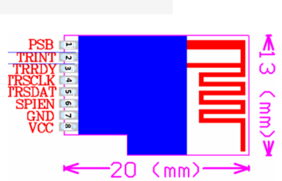
MS-RF005 size and pin diagram:

Page 3 of 5
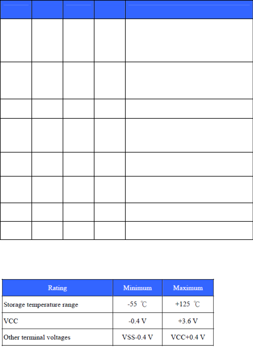
Pin Description:
Pin No Pin
Name I/O Active
State Description
1 PSB I Low
Digital input. Assert to force MS-RF005 to
enter Power-Saving Mode or Power-Down
Mode, depended on the state of TRRDY.
2 TRINT O High
Digital output. Asserted when transmitting or
receiving is accomplished.
3 TRRDY I High
Digital input. Assert to set the MS-RF005 to
Active Mode.
4 TRSCLK I/O N/A
Digital input at Burst Mode and digital output
at Direct Mode.Clock signal of the SPI/FIFO
interface.
5 TRSDAT I N/A
Digital input/output. Data signal of the
SPI/FIFO interface.
6 SPIEN I High
Digital input. Enable signal of the SPI
interface.
7 GND P N/A Ground.
8 VCC P N/A Digital power pin. +3.3VDC.
Electrical Specifications:
Absolute Maximum Ratings

Page 4 of 5
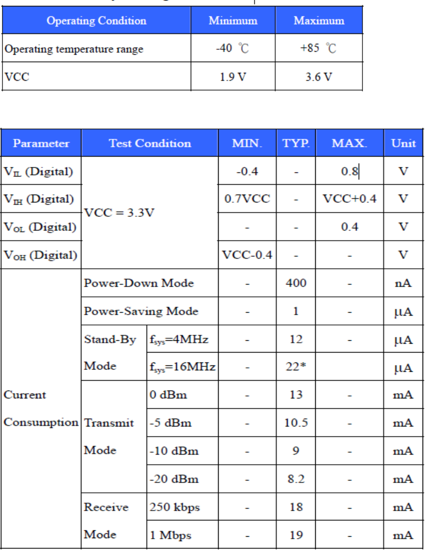
Recommend Operating Conditions:
DC Electrical Characteristics

Page 5 of 5
IMPORTANT NOTE:
This module is intended for OEM integrator. The OEM integrator is still responsible for the
FCC compliance requirement of the end product, which integrates this module.
Any changes or modifications not expressly approved by the manufacturer could void the
user’s authority to operate this equipment.
Declaration the Restriction of this Limited Module Approval:
According to FCC Part 15 Subpart C Section 15.212, the radio elements of the modular
transmitter must have their own shielding. However, due to there is no shielding for this RF
GFSK Module, this module is granted as a Limited Modular Approval. Due to missing
shielding the module is strictly limited to integration by the Grantee himself or his dedicated
OEM Integrator.
USER MANUAL OF THE END PRODUCT:
In the user manual of the end product, the end user has to be informed that the equipment
complies with FCC radio-frequency exposure guidelines set forth for an uncontrolled
environment.
The end user has to also be informed that any changes or modifications not expressly
approved by the manufacturer could void the user's authority to operate this equipment.
If the size of the end product is smaller than 8x10cm, then additional FCC part 15.19
statement is required to be available in the user manual: This device complies with Part 15 of
FCC rules. Operation is subject to the following two conditions: (1) this device may not cause
harmful interference and (2) this device must accept any interference received, including
interference that may cause undesired operation.
LABEL OF THE END PRODUCT:
The final end product must be labeled in a visible area with the following" Contains TX FCC
ID: AZK-RF005 ". If the size of the end product is larger than 8x10cm, then the following
FCC part 15.19 statement has to also be available on the label: This device complies with Part
15 of FCC rules. Operation is subject to the following two conditions: (1) this device may not
cause harmful interference and (2) this device must accept any interference received,
including interference that may cause undesired operation.
0700