MEIAN Technology MC-235R WIRELESS PIR DETECTOR User Manual MC 235R DMT Q20100506
Shenzhen Meian Technology Co.,Ltd . WIRELESS PIR DETECTOR MC 235R DMT Q20100506
Users Manual
MC-235R WIRELESS PIR DETECTOR
MC-235R is PIR intrusion detector with Pet immunity. It adopts
digital microprocessor control technology. By using refined
cylindrical FRESNEL lens in PIR section, it has high energy receiving
efficiency and high sensitivity and false alarm immunity. With
advanced patented software technology, It well settles the false
alarm and malfunction caused by other interference factors. It has
ultra-high detecting sensitivity and excellent anti-False alarm
performance. It is widely used in various indoor applications by
choosing proper pulse quantity. Special battery-saver feature
and working life is up to more than 2 years.
Model:
MC-235R
Detection distance:9m(25℃ )
Emitting distance:120-150m(in open area)
Operating voltage:6V(4 *1.5 V)
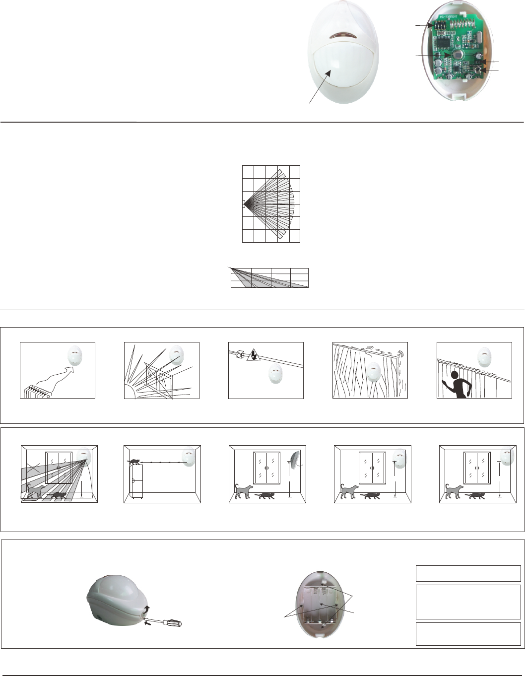
Infrared section(as shown in the figure)
Optical lens data
Infrared area:11+5 (typical)
Max.coverage:9 m*9m (23*46feet)/90°
Emitting frequency:433MHz
Alarm indication:LED flashes for seconds.
Mounting:
Wall or corner mountable,2.0-2.4m above
ground
Operating environment:
Operating temp:-10℃-50℃ (14℉-122℉ )
Storage Temp.:-20℃-60℃ (-4℉-140℉ )
Anti-white light(indoor) :>9000LUX
Dimensions:(L*W*H)94*62*53mm
3.Installation
2.Specification
3.1Notes
Wall mounting wide -angle lense view
Side view
2. 5 m
1. 5 m
0. 6 m
6m
4m
2m
7. 5
23 3 0
16,
5
2
,
,
,
8,
0,,,
XX
XX
9m
Do not face the cold and
heat source directly
Do not face the sunlight
directly
Keep wiring away from
high-voltage cable
Do not install on
unstable object
Do not face the
metal wall directly
1.Introduction
P/ N 201 10 5 06 - 2
Lense
PIR
Tamper
switch
0
1.5m
1.5m
3m
3m
4.5m
4.5m
10m
8m
6m
4m
2m
0
0
Jumper
switch
X
DIP
switch
Current consumption:
Static≤30μA,Alarm≤20mA(433MHz)
3.2 pet-immunity guidebook
The installation height of
2.2m to 2,4m is available
pet-immunity height
2.2- 2 . 4 m2.2- 2 . 4 m
≤15K g
the pet is smaller than 15kgthe top of the detecting
area is the non-pet-immunity
area
NO
OK
2.2- - 2 . 4 m
2.2- 2 . 4 m
≤20K g
15。
the pet is smaller
than 20kg
prevent direct the
places where the pets can
clamb up
X
3.3 Illustrated installation
Wall mount
②.Non bracket mounting:2.0-2.4m above the ground,Wall,
0
bracket or 45 corner mountable
B. Mark screw hole and drill
C. Insert two expandable
dowel and attach the
base to the wall with
two screws.
D. Replace the battery and
cover
①.Dismantle procedure:
A. Remove the screw by srewdriver
Bracket
mount
0
4 5
mount
Corner
8. Customer Service
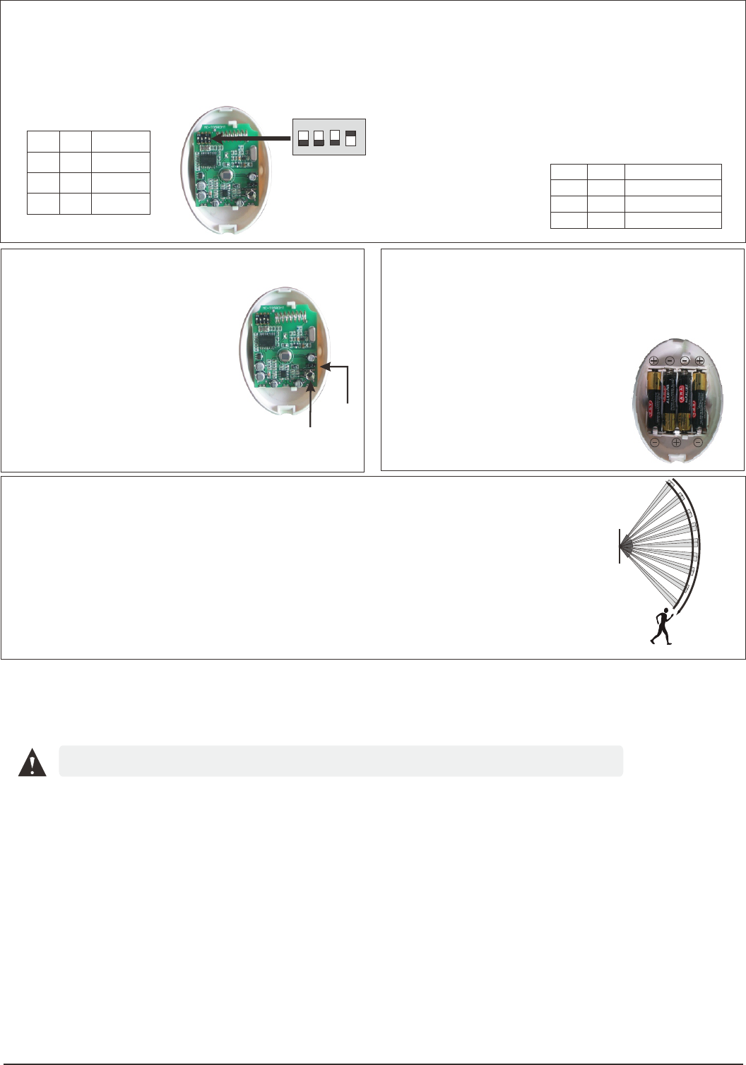
① Set as Test Mode to proceed walk-test,pulse count set as 1,2 or 3
③ Do walk-test in opposite direction to confirm the boundary of both sides, Make sure the
detection centre pointing to the centre of protected area.。
④ Make sure the detection centre at the proper place. Should properly adjust the detection
area if you can not get an ideal detection area.
② Walk across the far edge of coverage area at the speed of 1 step/second(about0.75m/s)
The LED will flash for seconds then alarm(as shown in the right figure)
7. Walk test in coverage area:
⑤ After adjust the detection angle , should redo the walk test as above.
⑥ Please change TEST mode to NORMAL mode after the Walk-test .
4.DIP switch functions:
MC-235R can set three modes as follows:
Test Mode:Emitting alarm signal once detector is triggered.
No time-lag between two emissions. Default mode
for installing test.
Power-saver mode:Detect every 3 minutes. Send detection
signal of detector and battery status
Coding Mode:Press tamper switch for more than 3 seconds
and send an identification code to receiver.
MC-235R can choose 3 kinds of pulse as follows:
1-pulse: Alarm 1-pulse.
2-pulse: Alarm 2-pulse。
3-pulse: Alarm 3-pulse (Factory defaul) 。
Higher pulse counting and lower catch performance
and can avoid false alarm
3
2
14
DIP
ON
Modes of DIP switch 3&4:
MODE
ON OFF TEST
OFF ON POWER-SAVER
OFF OFF CODING
34
1 2
MODE
1-Pulse
2-Pulse
3-Pulse
ON
ON
OFF
OFF
OFF OFF
Our products are very reliable,but for some special reasons, the working performance will be limited in certain range.
We here list some cases as follows:
①. The voltage of control panel is not stable; ②. Low-voltage of the detector.
For any help please contact with our company and your could visit our website for more information.
Warning: We are not responsible for the problem caused by improper operation by users!
5. Coding method between detector and
control pane and tamper switch setting:
① Coding set:
Install the battery,LED flashes,when
the detector gets stable after seconds,
press tamper switch for more than 3
seconds and detector will send a
wireless signal. If the control panel
receives the signal and get the response
sound then code successfully. Please
refer to control panel manual for details. ① Push here to
coding set
6.Detection distance adjustment and battery change
Pull out the base cover and change
battery. Please pay attention to the
positive and negative.
Polarity
② Jumper
② If short circuit of the jumper as shown
then tamper alarm function invalid
FCC WARNING
Changes or modifications not expressly approved by the party responsible for compliance could void the user's authority to operate
the equipment.
This equipment has been tested and found to comply with the limits for a Class B digital device, pursuant to Part 15 of the FCC
Rules. These limits are designed to provide reasonable protection against harmful interference in a residential installation. This
equipment generates uses and can radiate radio frequency energy and, if not installed and used in accordance with the instructions,
may cause harmful interference to radio communications. However, there is no guarantee that interference will not occur in a
particular installation. If this equipment does cause harmful interference to radio or television reception, which can be determined
by turning the equipment off and on, the user is encouraged to try to correct the interference by one or more of the following
measures:
-- Reorient or relocate the receiving antenna.
-- Increase the separation between the equipment and receiver.
-- Connect the equipment into an outlet on a circuit different from that to which the receiver is connected.
-- Consult the dealer or an experienced radio/TV technician for help.
once detector
is triggered.
The detector checks its batteries conditions when the batteries in
low voltage then it will transmit signals to warning users to
replace the batteries. It only transmit once to warn users.