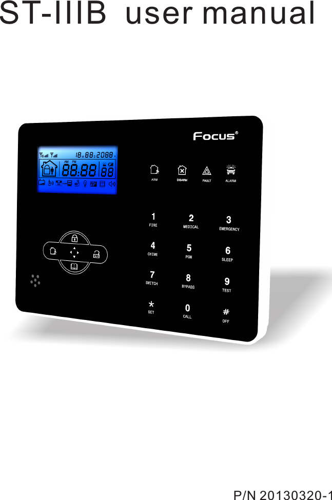
MEIAN Technology ST-IIIB ALARM CONTROL PANEL User Manual
Shenzhen Meian Technology Co.,Ltd . ALARM CONTROL PANEL
UserManual.wiki
>
MEIAN Technology
>
ST IIIB User Manual
User Manual
Navigation menu
Upload a User Manual
Namespaces
Wiki Guide
HTML
PDF
Info
Views
User Manual
Discussion / Help
Navigation
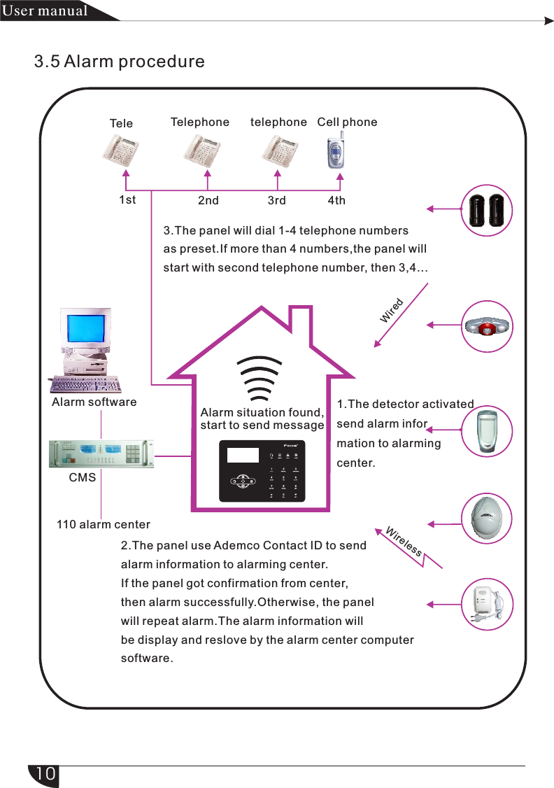
![7产品手册User manual3.2 Basic operationFactory defaultAdminitrator password: 01234516 User passwords, NO. 01 factory default is 1234. No. 02-16 of the user password is blank and can not enter the user setting untill user set the password.Home arm: Home arm keyArm: Arm keyEvent log: inquiry keyShutdown operation: AC power-off state ( press and hold for more than 3 seconds) + user password [1234]+Disarm: User password[1234]+DISARMEnter system setting: press and hold for more than 3 seconds+ adminstrator password [012345]+Enter user setting: Press and hold for more than 3 seconds+ user NO. (01) +user password(1234)+Zone inspection: Not insepct wired zones within one minutes of panel power upPassword reset: Enter 000000 to enter system setting menu within one minute of panel power up.3.3 Flashes when phone line cut. Light on when phone line is normal.Icon Meaning Detector low battery AlarmGSM is enabled Left behind Disarm Arm Enable GPRS +_G Voice promptsGSM signal strengthTelephone linePANEL battery low Icon Meaning##*#*#](https://usermanual.wiki/MEIAN-Technology/ST-IIIB/User-Guide-2313260-Page-12.png)

![*+321#4+123Set system clockSet user passwordSet voice phone5.1 Set system clock For example: set system clock as : 22:59:36 22/12/2012 *Press[*] for 3 seconds Please enter system clock, pressconfirm key tosave,press back key toexit.According to flash of Y.M.D.H.Min.Sec on screen, enter 12.12.22.22.59.36by turn, also can press [UP] [DOWN] key to move cursor.2 1 2 2 2 2 2593 6 #Y M D HMin Sec on screenEnter passord +++ ++ + ++ + + For example: Set No.16 user pasword as 5678 *Press[*] for 3 seconds#2#16+ + +++Enter password, press confirm key to save, press back key to exit.++76585.2 Set user password# Chapter IV Voice alarm receiving and GSM control产品 手册User manual1Enter passord 1234 Please enter the serial number of your modified password,confirm key to confirm,pressback key to exit.Note: Can set 16 user passwords, corresponding password No. from 01 to 16, Only No.1 password can enter user setting.#5.3 Set voice phone (refer to page 15)1 2 34 1 ##Press[*] for 3 seconds13](https://usermanual.wiki/MEIAN-Technology/ST-IIIB/User-Guide-2313260-Page-18.png)
![*8321012435676.1 Set passwordSet password2[2]Set user passwordX X X1[1]Set Admin passwordXXX#####549X X X #+ +Chapter VI System Setting*3210#54+ + + 1#Press[*] for 3 seconds产品 手册User manualSet passwordSet CMS numberSet voice phoneSet system optionsSet wireless devicesSet zoneSystem maintenanceSet GSMSet advanced optionsPress[*] for 3 secondsThen operate according to the voice prompt as below. Enter password, press confirm key to save, press back key to exit.The setting is saved Please enter the serial number of your modified password, confirm key to confirm, press back key to exit press confirm key to save, Enter password,press confrim key to save, Press back key to exitThe setting is saved14Note: 1. password setting include “user password” and “ administrator password”, user password mainly use to disarm the system, it is a private key for remote controlling, “administrator password” is the sole password to set the system.Note: 1. password setting include “user password” and “ administrator password”, user password mainly use to disarm the system, it is a private key for remote controlling, “administrator password” is the sole password to set the system.Note: 1. password setting include “user password” and “ administrator password”, user password mainly use to disarm the system, it is a private key for remote controlling, “administrator password” is the sole password to set the system.Note: 1. password setting include “user password” and “ administrator password”, user password mainly use to disarm the system, it is a private key for remote controlling, “administrator password” is the sole password to set the system.Note: 1. password setting include “user password” and “ administrator password” user password mainly use to disarm the system, it is a private key for remote controlling, “administrator password” is the sole password to set the system.](https://usermanual.wiki/MEIAN-Technology/ST-IIIB/User-Guide-2313260-Page-19.png)
![For example: Set admin pasword as 888888#1#1#8888#*3210548 8+ + + ++Press[*] for 3 seconds6.2 Set CMS numberThen operate according to the voice prompt as below:#1#2345# # #2#*3210#54+ + +Press[*] for 3 seconds+XX #XXX #X XX#X XX #X产品 手册User manual2.Administrator password is 6 digit, user password is 4 digit, can set 16 user passwords, corresponding password No. from 01 to 16, but No.2-16 password can’t enter user setting.3.If forgot the password, when the alarm is powered on, for the first minute,the administrator password is 000000.Enter password Enter password,press confirm key to save, press back key to exitNote: 1.Above base on the correct operation, if incorrect operation occurs, please press back key to back previous menu to reset. 2.The factory default of admin password is 9876, user password is 1234, if you have modified the password, please refer to the new password.Set CMS [1] Set CMS phone number [2] Set CMS phone no.2 [3] Set User Number [4] Set CMS dialing times [5] Set CMS communication test interval time Please enter phonenumber, press * key todelete, Long press 1, dialing pause 1 second,press confirmkey to save, press back key to exit. Please enter account No. press confirm key to save, press back key to exit Please enter dialing times, press confirm keyto save, press back key to exit Please enter communication inspection interval time, 0 for disable, press confirm key to save, press back key to exitThe setting is savedThe setting is savedThe setting is savedThe setting is saved15](https://usermanual.wiki/MEIAN-Technology/ST-IIIB/User-Guide-2313260-Page-20.png)
![Press[*] for 3 secondsEnter password #91 8 08080#2#321054 1 #*+ + +++80+3#*3210#54+ + +#1#23#4#5#6#XX #X XX #X XX #X产品 手册User manualNote: 1.The user code is the identification code in CMS setting, CMS 1 and CMS 2 use the same user code; dialing times can be set 1-15 , communication inspection interval time can be set 0-999 hours, the common setting is 24 hours. 2.When set phone number, long press 1, display the letter P, means pause 1 second when dialing, when the telephone line which connect to the alarm panel is sub-line, need a pause dialing. 3.For GSM, just recognize the number behind P, can make sure telephone and GSM dial the same number.For example: the sub-line connect to alarm panel, CMS number is 80808080, in this way, set CMS number like this 9P80808080, 9 is out code. Please enter phone number, press * key to delete, Long press 1, dialing pause 1 second, press confirm key to save, press back key to exit. Press[1] key for 3 seconds.6.3 Set voice phonePress[*] for 3 seconds Then operate according to the voice prompt as below: Set voice phone [1] Set voice phone 1 [2] Set voice phone 2 [3] Set voice phone 3 [4] Set voice phone 4[5] Set voice phone dialing times [6] Set voice phone passwordinspection [5] Set voice phone dialing times The setting is savedThe setting is savedThe setting is saved1.Enable 2.Disable Please enter phone number, press * key to delete, Long press 1, dialing pause 1second, press confirm key tosave, press back key to exit. Please enter dialing times, press confirm key to save, press back key to exit.16](https://usermanual.wiki/MEIAN-Technology/ST-IIIB/User-Guide-2313260-Page-21.png)
![For example: Set voice phone No.3 is 12345678*Press[*] for 3 seconds#3#Enter password + + +3210 54 3#++43216578#+*812435676.4 Set system optionsPress[*] for 3 seconds4#93210#54+ + +6.4.1 Set system clock *#4#1#1212 2 2 2 2 5932105436#+ + ++ + ++ ++++产品手册User manualNote:1.dialing times can set 1-15 2.When panel call user’s phone, if you enable password check, it will prompt enter user password when pick up the call. Please enter phone number, press * key to delete, Long press 1, dialing pause 1 second, press confirm key to save, press back key to exit.Set system clockSet entry delaySet exit delaySet siren timeSet ring timesSet detector loss inspectionSet arm/disarm toneSet arm/disarm reportSet others According to flash of Y.M.D.H.Min.Sec on screen, enter 12.12.22.22.59.36 by turn, also can press [UP] [DOWN] key to move cursor.For example: Set system time to 22:59:36 22/12/2012Press[*] for 3 secondsEnter passwordPlease enter system clock, press confirm key to save, press back key to exit. Y M D H MinSec on screen17](https://usermanual.wiki/MEIAN-Technology/ST-IIIB/User-Guide-2313260-Page-22.png)
![*#4#2#032105420+#Enter 3 digit number from 0-255, add 0 if less than 3 digit.Enter password + ++ +*Enter password #4#3#032105420+#Enter 3 digit number from 0-255, add 0 if less than 3 digit.+ ++ +6.4.3 Set exit delayAfter user armed the system, it is convenient for user to exit the area after arm successfully.( the default setting is 10seconds)For example: Set exit delay time is 20sNote: Entry delay is just effective for delay zone. Other zone types can’t enter delay.+#4#4#32105410+#+ ++++*+产品 手册User manual6.4.2 Set entry delayWhen trigger alarm, the panel will give delay alarm time(default setting is 10s)For example: Set entry delay to 20secondsPress[*] for 3 seconds Please enter entry delay time, press confirm key to save, press back key to exitPress[*] for 3 secondsPlease enter exit delay time, press confirm key to save, press back key to exit6.4.4 Set siren time :The siren ring time after alarm is triggered( the default setting is 5 minutes)For example: Set siren time is 10 minutes Please enter 0 to 30 minutes siren time, press confirm key to save, press back key to exitPress[*] for 3 secondsEnter password6.4.5 Set ring timesUser remote control alarm panel, dail the preset phone number, the panel willoff-hook after phone ring times( the default setting is 7 times) For example: Set ring times is 518](https://usermanual.wiki/MEIAN-Technology/ST-IIIB/User-Guide-2313260-Page-23.png)
![#4#5#32105405+#+ ++++*Note: The max. Ring times as per the local communication, if set 0, not off-hook.#4#6#32105408+#*++ + + +#4#7#3210541+#*++ + ++产品 手册User manualEnter password.... Please enter ring times, if set as 0, the phone will not off hook, press confirm key to save,press back key to exitPress[*] for 3 secondsEnter passwordEnter 2 digit number from 0-15, add 0 if lower than 10.6.4.6 Set detector loss inspection The alarm panel will inspect the detectors’ status or alarm info in this time interval, if not receive, it is determined that the detector is loss, the general setting is not less than 6 hours( the default setting is 0, disable this function)For example: Set detector loss inspection time is 8 hours. Please enter 0 to 99 hours detector loss inspection time, 0 for disable, press confirm key to save, press back key to exitPress[*] for 3 secondsEnter password6.4.7 Set arm/disarm toneWhen user arm/disarm the system through remote control, if siren will sound or not for prompting.( the default setting is disabled)For example: Set siren with short sound when arm/disarm through remote control.Please choose arm/tone: 1. siren short sound 2. no voice, press confirm key to save, press back key to exit disarm Press[*] for 3 secondsEnter password19](https://usermanual.wiki/MEIAN-Technology/ST-IIIB/User-Guide-2313260-Page-24.png)
![#4#8#1#310542*+ + ++ ++*#4#9#310542812435679+ + ++#4#9#13105421#+ ++*++++#产品 手册User manualPlease choose arm/disarm report: 1. enable, 2. disable, press confirm key to save, press back key to exitPress[*] for 3 secondsEnter passwordSet AC off remind6.4.9 Set others6.4.9.1 Set emergency alarm siren type( the default setting is mute)For example: set emergency alarm siren type is pedal point.Please choose zone siren type: 1.pedal point 2.pulse tone 3. mute, press confirm key to save, press back key to exitPress[*] for 3 secondsEnter passwordSet emergency alarm siren typeSet AC off inspection timeEnable magnetic contact inspectionCheck wireless detector tamperSet force armSet telephone line disconnect remindSet zone alarm timesSet listen-in time6.4.8 Set arm/disarm report Set if arm/disarm report to CMS or not( the default setting is disabled)For example: Set arm/disarm report to CMS20](https://usermanual.wiki/MEIAN-Technology/ST-IIIB/User-Guide-2313260-Page-25.png)
![#4#9#01#3210542#5*+ + ++ + ++#4#9#1#3210543#*+ + ++ + ++#4#9#2#3210544#*+ + + ++ ++产品 手册User manual6.4.9.2 Ac off inspection time setting. When the AC power is off, delay to report to CMS(factory default delay time is 30 min)Example:set AC off inspection time as 15 minPress[*] for 3 secondsEnter passwordPlsease enter 0 to AC off duration time.pressconfirm key to save, pressback key to exit.255 minutes6.4.9.3 Magnetic contact inspection: Set if the alarm panel show zone trouble on LCD screen or not when sperate the magnetic strip from transmitter. (Factory default disable the inspection) Example: enbale the magnetic contact inspectionPress[*] for 3 secondsEnter password6.4.9.4 Check wireless detector tamper: if the enable the checking when trigger the detector’s tamper , will trigger alarm. If disable the checking, it will not trigger alarm.(factory default enable the checking)Example: disable the checking of wireless detector tamper.Press[*] for 3 secondsEnter password6.4.9.5 Set force arm: if enabel set force arm, when there is zone trouble, the system can be armed and report the trouble zone’s bypass message to CMS. If disable the force arm, the system can not be armed(factory default is disable forem arm)Example: enabel force armPlease choose: 1. Enable contact inspection 2. DisablePress confirm key to save, Pressback key to exit.magnetic Please choose : 1. Enable detector tamper inspection, 2. DisablewirelessPress confirm key to save, Pressback key to exit.21](https://usermanual.wiki/MEIAN-Technology/ST-IIIB/User-Guide-2313260-Page-26.png)
![#4#9#1#3210545#*+ + + ++ + +#4#9#3#3210546##4#9#2#3210547#*+ ++ + +++*+ + ++ ++#4#9#0#3210548#20*+ + ++ +++产品 手册User manualPress[*] for 3 secondsEnter passwordPress[*] for 3 secondsEnter passwordPress[*] for 3 secondsEnter password6.4.9.6 Set telehpone line disconnect remind(factory default delayed siren sound remind)Example : disable telephone line disconnet remind6.4.9.7 set zone alrm times: if set the alarm alarm times as 1, when zone start alarm but the zone is trigger one time again, the panel will not make alarm.Example: set zone alarm times as 1 time 6.4.9.8 set listen-in time(factory default 10 sec) Example: set listen-in time as 20secPress[*] for 3 secondsEnter passwordPlease choose: 1. Auto force 2. Forbid force arm via remotecontrol.arm Press confirm key to save, pressback key to exit. Please choose telephone line disconnect remind: 1. Siren delay remind, 2. Buzzer remind, 3 disable Press confirm key to save, Pressback key to exit. Please choose zone alarm times: 1. no limited 2. 1 time Press confirm key to save, Pressback key to exit. Please enter 10 to 255 seconds listen-in time Press confirm key to save, Pressback key to exit. 22](https://usermanual.wiki/MEIAN-Technology/ST-IIIB/User-Guide-2313260-Page-27.png)
![*#5#32105412435+ ++#4#9##3210549#3*+ + + ++ + +*#5#3210541231#+ + ++#5#1##3210541#3#*+ + + ++ + ++产品手册User manual6.4.9.9 Set AC off remind(factory default remind by SMS) Example:disable AC off remindPress[*] for 3 secondsEnter password6.5 manage wireless devicePress[*] for 3 secondsSet remote controlSet detectorsSet appliance switchEnroll wireless sirenSet door bellEnroll remote controlEnter remote control codeDelete remote control 6.5.1 set remote controlPress[*] for 3 seconds6.5.1.1 enroll remote control Example: enroll remote to the #3 remote in alarm panelPress[*] for 3 secondsEnter passwordPlease choose AC off remind: 1. SMS remind 2. Voice phoneremind 3. Disable Press confirm key to save, Pressback key to exit. Please enter the serial number of remote control Press confirm key to save, Pressback key to exit. Please trigger the remote controlPressback key to exit. Enroll successfulTrigger arming key on the remote control23](https://usermanual.wiki/MEIAN-Technology/ST-IIIB/User-Guide-2313260-Page-28.png)
![#5#1##3210542#8211 11 13 41 #*+ + ++ + +++#5#1##3210543#5*+ ++ + + ++*#5#3210541232#+ ++ +#5#2#3210541#09#*+ + +++++#+产品 手册User manual6.5.1.2enter remote control codeExample: manaul enter the address code of remote 112113114 to the #8 remote in alarm paPress[*] for 3 secondsEnter password6.5.1.3 delte remote controlExample: delete the # 5 remotePress[*] for 3 secondsEnter password6.5.2 set detectorPress[*] for 3 seconds Detector codingEnter detector codeDelete detector6.5.2.1 detector codingExample: auto code detector to # 9 detector in alarm panelPress[*] for 3 secondsEnter passwordPlease enter the number of remote control.serial Press confirm key to save, Pressback key to exit. Press confirm key to save, Pressback key to exit. Please enter remote control Number +Please enter the serial number of remote control to delete, enter 0 to delete all. Press confirm key to save, Pressback key to exit. Press confirm key to save, Pressback key to exit. Please enter detector Number Please trigger the detectorPressback key to exit. Enroll successful trigger the detector24](https://usermanual.wiki/MEIAN-Technology/ST-IIIB/User-Guide-2313260-Page-29.png)
![#5#2#3210542#070011022 3 3 ##5#2#3210543#03#*#5#3#32105412*+ + +++++*++ + ++ + ++#+++ + ++#5#3#3210541#1##*+ + ++ + +++产品 手册User manualPress[*] for 3 secondsEnter password6.5.2.2 enter detector codeExample: manual enter the address code of detector 011022033 to the # 7 detector in alarm panel6.5.2.3 delete detectorExample: delete the # 3 detectorPress[*] for 3 secondsEnter password6.5.3 set appliance switchPress[*] for 3 secondsEnroll appliance switchDelete appliance switch6.5.3.1 enroll appliance switchExample: auto the appliance to the # 1swith in alarm panelPress[*] for 3 secondsEnter passwordP l e a s e e n t e r detector Number. Press confirm key to save, Pressback key to exit. Please enter detector code Press confirm key to save, Pressback key to exit. Please enter the serial number of detector to delete, enter 00 to delete all. Press confirm key to save, Pressback key to exit. Please enter the serial number of appliance switch Press confirm key to save, Pressback key to exit. Pressback key to exit. Please trigger appliance switchTrigger appliance switch Enroll successful25](https://usermanual.wiki/MEIAN-Technology/ST-IIIB/User-Guide-2313260-Page-30.png)
![#5#3#3210542#4#12*#5#4#321054#5#4#3210541###*+ + + ++ +*+ + ++ + +++ + +++#5#4#3210542##按 3秒以 上[*]*++ + +++产品 手册User manual6.5.3.2 Delete appliance switchPress[*] for 3 secondsEnter passwordEnroll wireless sirenDelete wireless siren6.5.4 Enroll wireless siren6.5.4.1 Enroll wireless sirenPress[*] for 3 secondsEnter passwordNOTE: when dual-way wireless siren make tamper alarming, the LCD screen of alarm panel will display zone 41 alarming.6.5.4.2 Delete wireless sirenNote: It is dual-way wireless siren deleted. Please enter the serial number of appliance switch to delete, enter 0 to delete all Press confirm key to save, Pressback key to exit. Please make wireless siren under coding status, then pressconfirm key to start coding. Make wireless siren under coding statusStart siren coding, please operate as voice prompting Pressback key to exit. This is one way wireless siren Press confirm key to save, Pressback key to exit. This is 2-way wireless siren Press confirm key to save, Pressback key to exit. Delete wireless siren Press confirm key to save, Pressback key to exit. Enter password26Example: delete the # 4 appliance switch](https://usermanual.wiki/MEIAN-Technology/ST-IIIB/User-Guide-2313260-Page-31.png)
![#5#5#3210541# #12*#5#5#3210546.5.5.1Enroll doorbell Note: can only learn a wireless doorbell, the trigger will be issued after the chink #5#5#3210542# #*+ + ++ +*+ + ++++ + +++6.5.5.2 Delete doorbell++6.6 Sector Settings*#6#32105412345++ +产品 手册User manual6.6.5 Set door bellSet zone attributionSet zone siren typeSet wired zone loop typeSet wired zone response speedSet related zonePress[*] for 3 seconds6.6.1 set zone attribution The type of zone attributuion is as below: 0)disable zone 1> delay zone 2> perimeter zone 3>inerior zone 4>emergency zone 5> 24 hours zone 6>fire zone 7> key zoneEnroll doorbellDelete doorbellPress[*] for 3 secondsEnter passwordPress[*] for 3 secondsEnter passwordPlease trigger doorbell Pressback key to exit. Please trigger doorbell Enroll successful Press confirm key to save, Pressback key to exit. Delete doorbell271.Zone attribution is the alarm type of the zone display on the alarm panel’ s LCD screen when the zone is triggered. When set the zone attribution as 0 is to disable the zone. The alarm panel will not make alarm when trigger this zone.](https://usermanual.wiki/MEIAN-Technology/ST-IIIB/User-Guide-2313260-Page-32.png)
![#6#1#3210543#9*+ + ++ ++7#+ +Example: set zone 39 as keyzone type2.interior zone only trigger alarm when the zone is triggered under system at armed status.3.delay and perimeter zone trigger alarm when the zone is triggered under system at armed or home arm status.4.emergency zone, 24 hours zone, fire zone will trigger alarm when system at any status5.wirelss zone can not set key zone type. When wired zone is set as keyzone, trigger the zone, system turn to disarm status. The zone restore, system turn to armed status. This is for access contron system.#6#2#3210542#3*++ + ++ +产品 手册User manualPress[*] for 3 secondsEnter password6.6.2 set zone siren type(factory default is pefal point)Example set zone 23’s siren type as pulse tone Enter passwordPress[*] for 3 secondsPlease enter the zone No. to modify. Press confirm key to save, Pressback key to exit. Please choose zone type: 0. Disable the zone 1. Delay zone 2. Perimeter zone 3. Interior zone 4. Emergency zone 5. 24 hours zone 6. Fire zone 7. Key zonePlease enter the zone number to modify. Press confirm key to save, Pressback key to exit. Please choose zone siren type: 1.pedal point 2.pulse tone 3. Mute Press confirm key to save, Pressback key to exit. #2+ +6.6.3 set wired zone loop type(factory default EOL ) The options is as below:281>EOL loop type: when the resistor value is 10k on the zone is normal, when the zone is open loop or shortcut trigger alarm2>N/C loop type: zone shortcut is normal, open loop trigger alarm3>N/O loop type: zone open loop is normal, shortcut loop trigger alarm](https://usermanual.wiki/MEIAN-Technology/ST-IIIB/User-Guide-2313260-Page-33.png)
![#6#3#321054#3#53#6#4#321054#4#02*+ + ++ ++ ++*+ + ++ ++ ++NC10KΩNO 10KΩ 6.6.5 set related zone: zone 1+zone 2+related time+mode The options as belows 0>disable related zone mode 1>EXIT-ENTRANCE dual trigger mode: trigger zone 1 or 2 seperately will not trigger alarming. Trigger zone 1 first, then during the period of related time trigger zone 2, then both zone 1 and 2 trigger alarm.Trigger zone 2 first, then trigger zone 1 will not trigger alarm.ZCZC产品手册User manual EOL loopN/C wiring diagram EOL loopN/O wiring diagram6.6.4 set wired zone response speed(factory default is 500 millisecond)Press[*] for 3 secondsEnter passwordExample: set zone 35 as N/O loop typePress[*] for 3 secondsEnter passwordNote: Normall the detector’s response speed is 500 millisecond, high speed response detector like vibration detector is 10 millisecondPlease enter the zone number to modify Press confirm key to save, Pressback key to exit. Please choose loop type: 1.EOL 2.N/C, 3.N/O Press confirm key to save, Pressback key to exit. Please enter the zone numbEr to modify Press confirm key to save, Pressback key to exit. Please choose loop response speed: 1. 500ms, 2. 10ms Press confirm key to save, Pressback key to exit. 29](https://usermanual.wiki/MEIAN-Technology/ST-IIIB/User-Guide-2313260-Page-34.png)
![#6#5#321054#4#5#0NOTE: max set 4 group relate zone6.7 system maintance*#7#321054123456*+ + ++ ++ ++0+9#2+ +01#+ +3+ +++产品 手册User manual2>EXIT-ENTRANCE single trigger model: trigger zone 1, zone 1 make alarm. Trigger zone 2 first, then during the period of related time trigger zone 1, do not make alarm. Trigger zone 2, then do not trigger zone 1 during related time, then zone 2 make alarm.3> Dual trigger alarm mode: trigger zone 1 or zone 2 only do not make alarm. During related time trigger zone 1 or zone 2, then zone 1 or zone 2 make alarm. Example: set zone 5 and zone 9 as greep #4 dual trigger mode related zone, related time is 120sec.Press[*] for 3 secondsEnter passwordPress[*] for 3 seconds Set timing arm /disarm Recording Play recoreding Set programmable output port Delete system log Restore to factory default Eneter correlate group # , press confirm key to confirm or press back keyto exit setting. Enter the firstcorrelate zone # press confirm key to savesetting, or press back key to exit setting. Settingsaved, enter second related zone #, press confirm key to save setting or press back key to exit settingSetting is saved, press set relate time from 2 to 255sec, and press confirm key to save setting, or press back key to exit settingSetting is saved, pls choose relate mode. 0 disable relate mode , 1 entrance-exit dual trigger mode, 2 entrance-exit single trigger mode, 3 dual trigger mode. Press confirm key to save setting or press back key to exit.30](https://usermanual.wiki/MEIAN-Technology/ST-IIIB/User-Guide-2313260-Page-35.png)
![#7#1#3210541#70*+ + +++ ++30830##7#2#321054*++++#+3+#7#3#321054*+ ++++6.7.1 Set timing operationExample: Set group No.3 as timing disarm at 8:30, and timing arm at 17:30[*]Press for 3 seconds产品手册User manualEnter password[*]Press for 3 secondsEnter passwordPlease enter timing arm/disarm group number Please enter timing arm time, 00 is invalid time.Press confirmkey to save, pressback key to exit.Please enter timing disarmtime, 00 is invalid time. Press confirm key to save, press back key to exit.Hint: 4 groups of timing arm/disarm can be set according to the schedule of user.6.7.2 RecordingStart to record when you hear “Bi” soundHint: 15 seconds for recording time. And it will play recording as soon as the panel dial to the telephone No.as preset.6.7.3 Play recordingPress * for 3 seconds.Enter password6.7.4. Set programmable output port: the voltage will change from 0V to 14.5V as soon as some events occurs. (Default is follow alarm output)Trigger events can be set as below 1. Follow alarm output 2. Follow arm output 3. Follow AC power fault output 4. Follow communication fault output 5. Password control outputPlay the recording31](https://usermanual.wiki/MEIAN-Technology/ST-IIIB/User-Guide-2313260-Page-36.png)
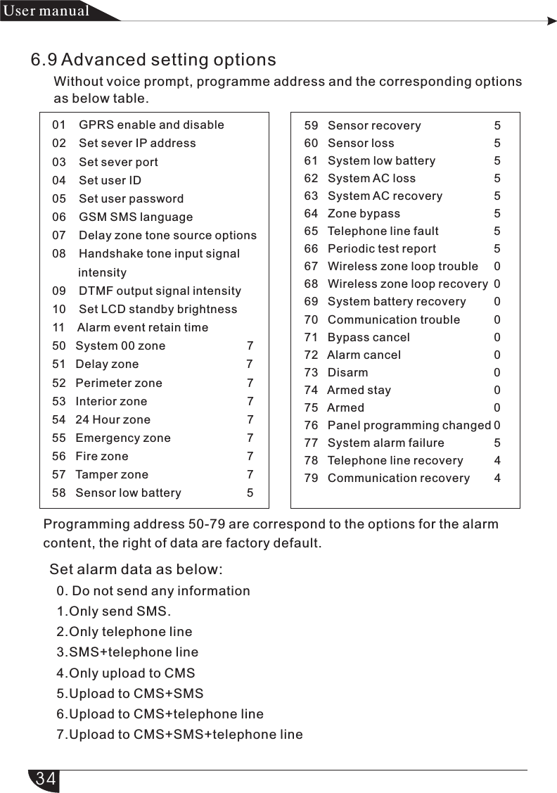
![#7#4#321054#5*#7#5#321054#*#7#6#321054#*+ + ++ +++++ +++++ + +产品 手册User manualFor example: Set as password control outputPress[*] for 3 secondsEnter passwordPlease select programmable output port follow event 1.Follow alarm output 2.Follow arm output 3.Follow AC power fault output 4.Follow Communication fault output 5.Password control outputHint: when setting as password control output, press key 5 for 3 seconds, then enter the user password, the programme output port will be open or closed. Voice phone or SMS also can open or close the outport.Press[*] for 3 secondsEnter password6.7.6.Restore to factory defaultPress * for 3 secondsEnter passwordPlease re-confirm to restoreto factory default.Press confirm key to save, press back key to exit.Please re-confirm to restore to factory default.Press confirm key to save, press back key to exit.*#8#321054+ ++6.8. Set GSM modulePress[*] for 3 secondsFor example: Set enable GSM module, telephone line priority, Set GSM bill reminder time is 21st Dec. 2012.The voice prompt will instruct you to proceed below operations.326.7.5.Delete system events](https://usermanual.wiki/MEIAN-Technology/ST-IIIB/User-Guide-2313260-Page-37.png)
![[1]Set GSM disabled/enabled[2]Set GSM in priority# # ##1#2#212121#[3]GSM signal display[4]Set GSM bill reminder time321 4产品 手册User manualSet GSM module Please choose 1> enable GSM 2> disable GSM, Press confirm keyto save, pressback key to exit. The maximum signal intensity can be displayed in LCD is 31, press back key to exit. Please choose 1> GSM in priority2> PSTN in priority, Press confirm key to save, press back key to exit. Please enter SIMcard expiry time, Press confirm key to save, press backkey to exit.The setting is savedThe setting is savedThe setting is savedHint: The alarm control panel will send SMS to cellphone as preset and remind you to recharge as you set GSM bill reminder time before or after ten days.33](https://usermanual.wiki/MEIAN-Technology/ST-IIIB/User-Guide-2313260-Page-38.png)
![LCD display directionYDM*#9#0321054#+1+1++ +++*#9#321054#++20+01035+ +19800 0 3+ + ++产品 手册User manualProgramming address Press key up and down to check and modify the different data of the data bit.Data Data bit6.9.1 GPRS enable and disable(1. Enable 2. Disable default is 2 )For example: set enable GPRSPress[*] for 3 secondsEnter passwordLCD display Programming address Data LCD displayHint: Priority to enable the GSM module before enable the GPRS6.9.2 Set sever IP address For example: Sever IP address is 103.59.108.3Press[*] for 3 secondsEnter passwordLess than 3 bits high zero.35](https://usermanual.wiki/MEIAN-Technology/ST-IIIB/User-Guide-2313260-Page-40.png)
![*#9#321054#++40+0505 5 50 0*#9#321054#++30+0808 8++++++*#9#321054#++50+21 435 768+ ++*#9#321054#++60+2+ ++产品 手册User manual6.9.3 Set sever portFor example: Sever port as 80808Press[*] for 3 secondsEnter password6.9.4 Set user IDFor example: User ID as 50505050Press[*] for 3 secondsEnter passwordUser ID must be 8 bits6.9.5 Set user password For example: User password as 12345678Press[*] for 3 secondsEnter passwordUser password must be 8 bits6.9.6 GSM SMS language(1. Chinese 2. English Default is 1 Chinese)For example: Set GSM SMS language as EnglishPress * for 3 secondsEnter password36](https://usermanual.wiki/MEIAN-Technology/ST-IIIB/User-Guide-2313260-Page-41.png)
![*#9#321054#++70+3*#9#321054#++80+076.9.9 DTMF output signal intensity(The default is 04)For example: set the DTMF output signal strength to 06*#9#321054#++90+60+ +++ +++++*#9#321054#++01+80+++产品 手册User manual6.9.7 Delay zone tone source options 1. Dingdong 2. Welcome 3. Recording 4. Didi For example : Delay zone tone source as recordingPress[*] for 3 secondsEnter passwordHint: In disarm mode, once delay zone triggered and above 4 voices will be generated. press key 4 for 3 seconds and input the user password can be open and close it.When the tone source is recording mode, the voice phone will not play the recording.6.9.8 Handshake tone input signal intensity ( default is 60)For example: set it as 70Press[*] for 3 secondsEnter passwordPress[*] for 3 secondsEnter password6.9.10 Set LCD standby brightness (default is 02)For example: Set it as 22Enter passwordPress[*] for 3 secondsBrightness range: 0-10,Less than 2 bits high zero37](https://usermanual.wiki/MEIAN-Technology/ST-IIIB/User-Guide-2313260-Page-42.png)
![For example: set the alarm information retention time is 255 minutes*#9#321054#++11+525+++产品 手册User manual6.9.11 Alarm event retain time When telephone line and GSM all fault, the alarm event will be retained in the preset time. Otherwise it will loss. After telephone line and GSM recovery, it will upload to the CMS. (default time is 10 mintus).Retain time :1-255 mintus.Less than 3 bits high zero.Press[*] for 3 secondsEnter password38](https://usermanual.wiki/MEIAN-Technology/ST-IIIB/User-Guide-2313260-Page-43.png)