Meneghetti RUEI Induction Cooking Range with Oven User Manual Installation Manual
Meneghetti SpA Induction Cooking Range with Oven Installation Manual
UserManual.wiki
>
Meneghetti
>
RUEI User Manual
>
Installation Manual
Contents
1.
Installation Manual
2.
User and Care Manual
Installation Manual
Navigation menu
Upload a User Manual
Namespaces
Wiki Guide
HTML
PDF
Info
Views
User Manual
Discussion / Help
Navigation
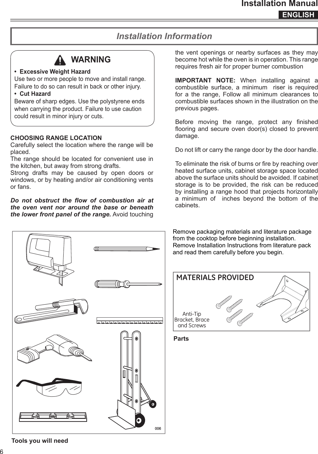
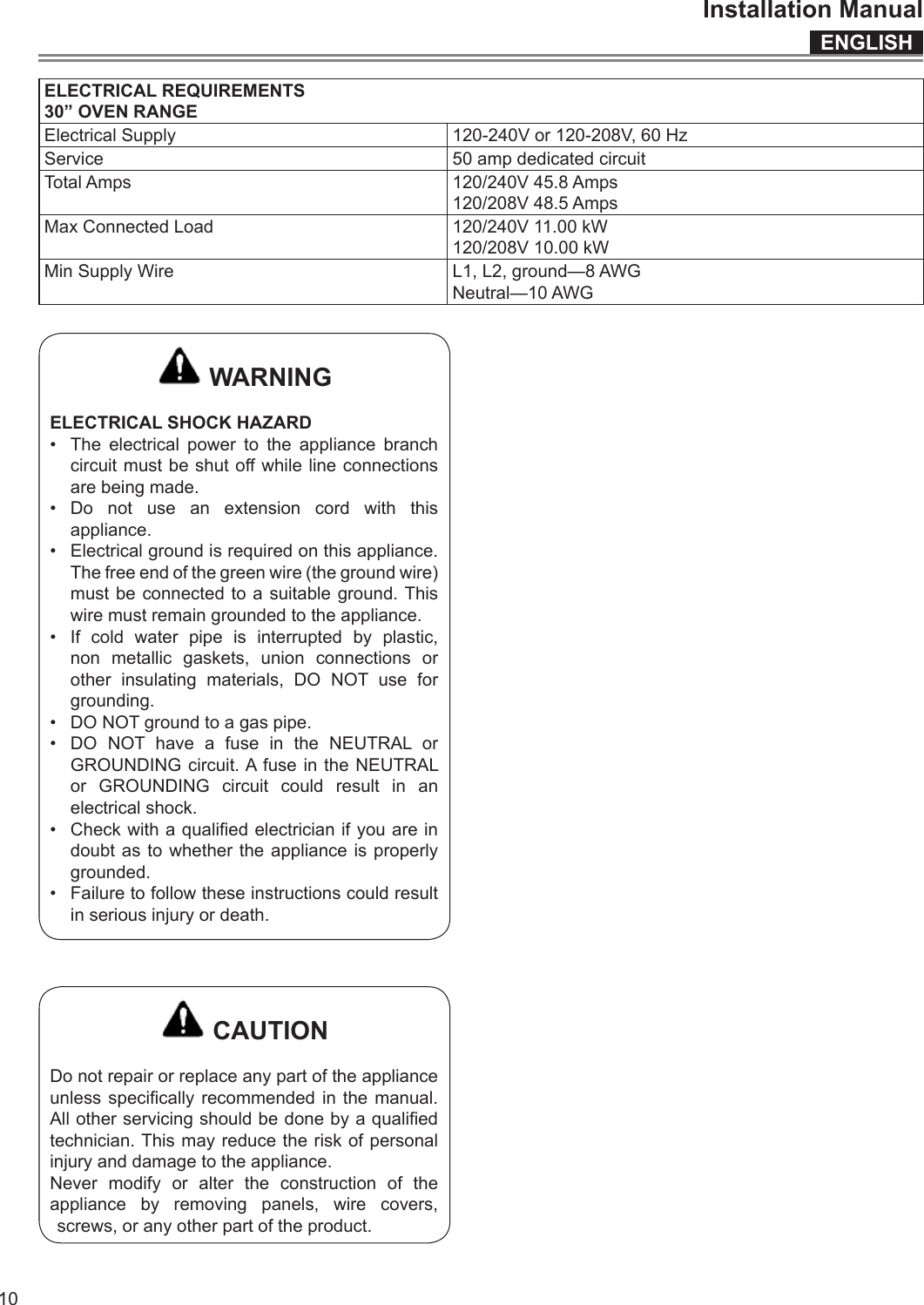
![ENGLISHInstallation Manual329-3/4” (75,8)36-1/8”(91,7)3" (7,6) or9" (22 ,8) [optional]27-1/4”(69,1)27-1/4”(69,1)27 1/2”(69,7)7 3/8” (18,7)29-3/4”(75,6)47 3/4” (121,4)2 1/8” (5,5)4 3/8” (11,0)TO Product Dimensions and Cutout Requirements IMPORTANT Special Warnings Please read all instructions before using this appliance. Product dimensions30” Wide Range Models](https://usermanual.wiki/Meneghetti/RUEI.Installation-Manual/User-Guide-2967491-Page-4.png)
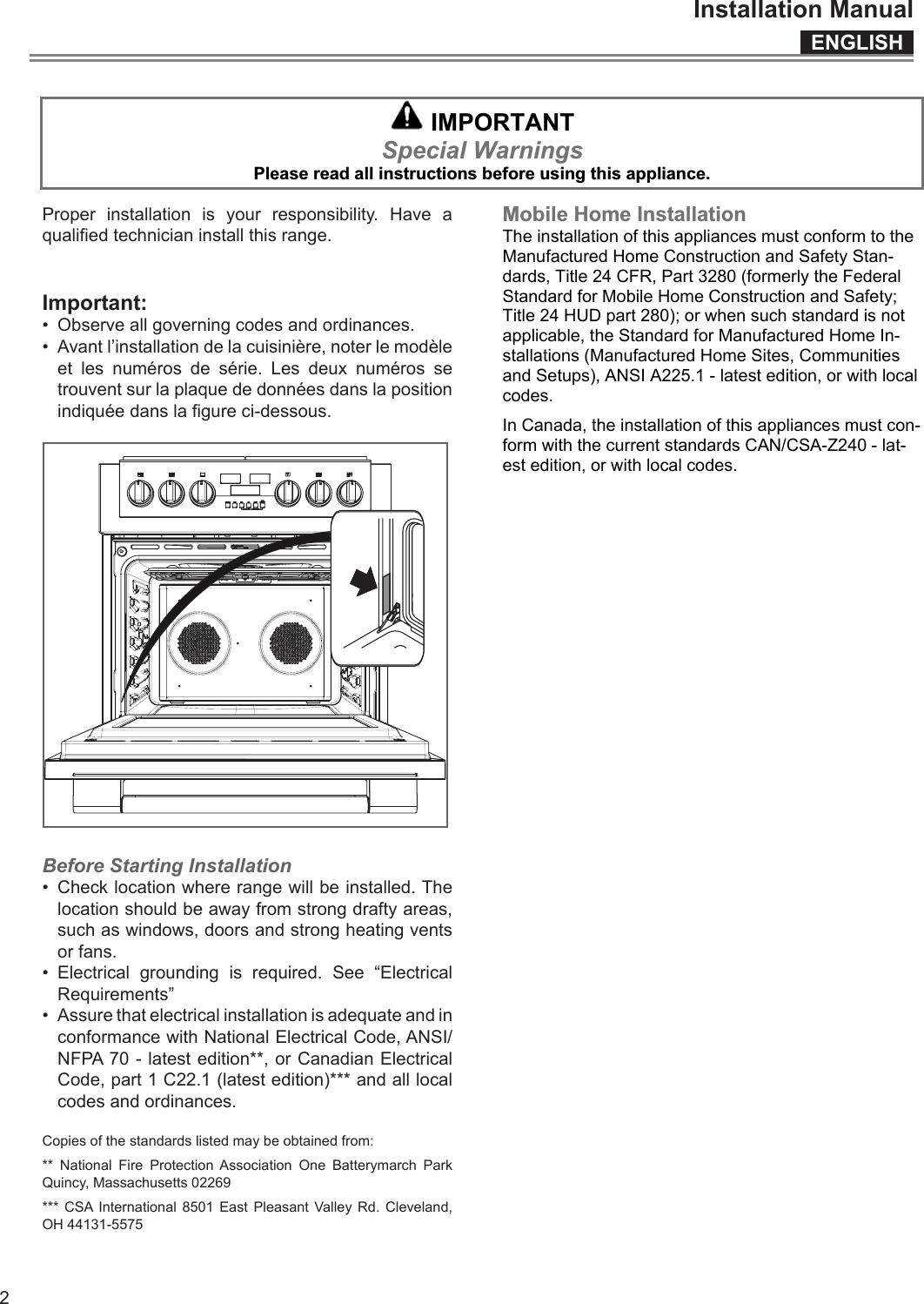
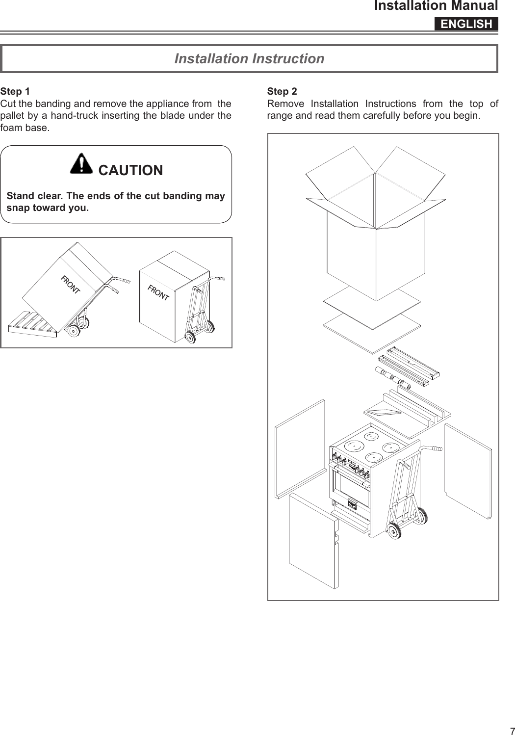
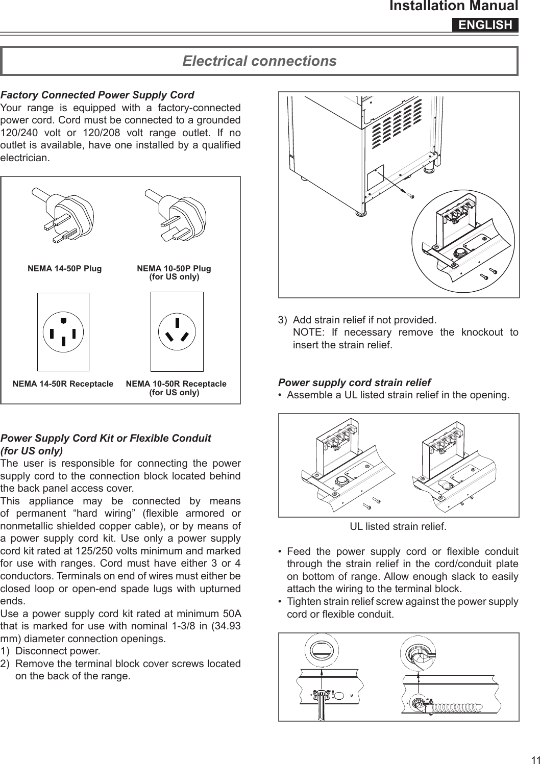
![ENGLISHInstallation Manual4ABackmin 2-½” (6,3)min 18”(45,7)SHADED AREA:The surface of the entire back wall above the range and below the hoodmust be covered with a noncombustible material.min 30”(76,2)min6”(15,2)min3”(7,6)min3”(7,6)3”( 9 )GAS ELECTRICmin4 3/4”(12,3)BBmin6”(15,2)*Suggestedlocation ofutilities*Consult local code for exact location requirements. min 18”(45,7)Minimumto Combustiblesorto botton of ventilation hoodADDITIONAL CLEARANCES:For island installation, maintain 2-½ in. minimum fromcutout to back edge of countertop and 3 in. minimumfrom cutout to side edges of countertop (see top view).OPENING WIDTH A & C BRange 30" 30" (76,2) 6" (15,2) Clearances to non-combustible materials must conform with local codes or, in the absence of local codes,with the National Fuel Gas Code, ANSI Z223.1/NFPA 54.Minimum clearances:Above cooking surface (above 36” [91.4 cm])• Sides - 3” (7.6 cm)• Within 3” (7.6 cm) side clearance, wall cabinets no deeper than 13” (33.0 cm) must be minimum18” (45.7 cm) above cooking surface• Wall cabinets directly above product must be a minimum of 30” (76.2 cm) above cooking surface.• Rear - 0” with 3 ” (7.6 cm) backguard.2” (5,1) max.protusion from wallfor gas or electrical supplyCmax13”(33)Cutout requirements](https://usermanual.wiki/Meneghetti/RUEI.Installation-Manual/User-Guide-2967491-Page-5.png)
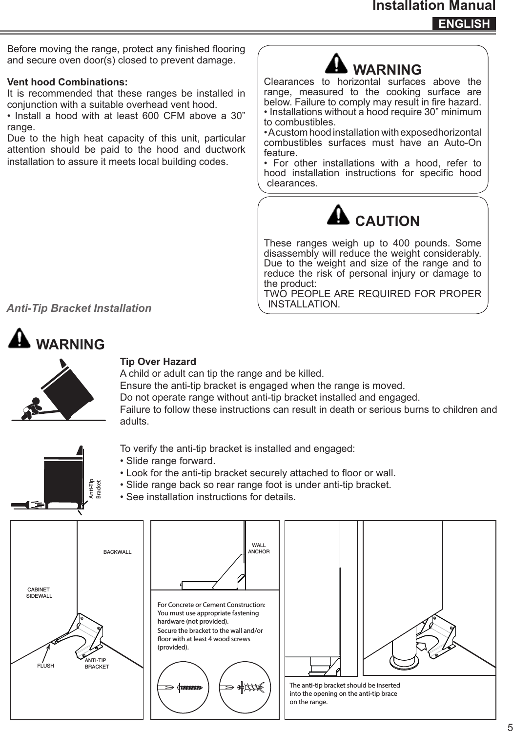
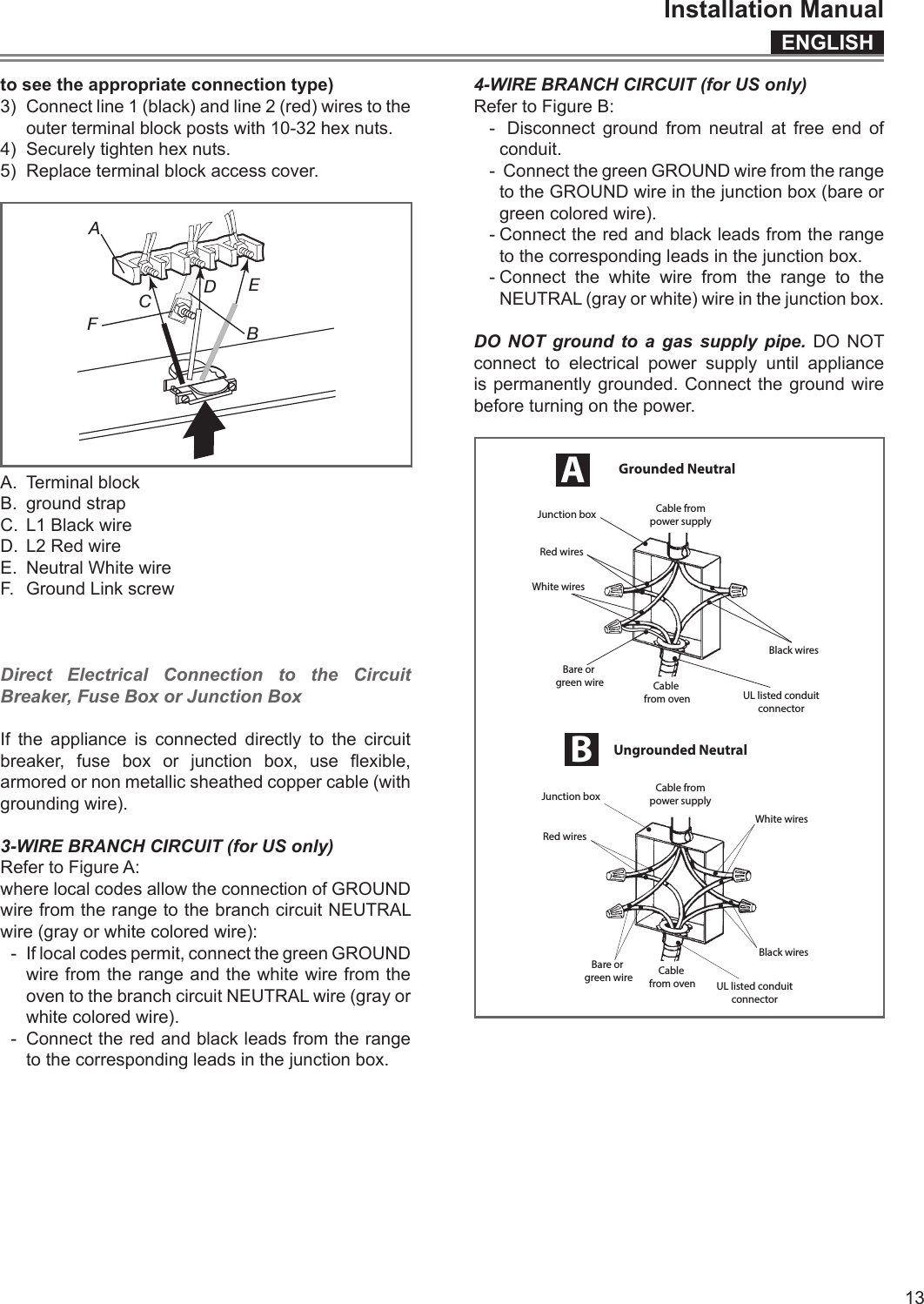
![ENGLISHInstallation Manual14To prevent improper connections leading to damage of electrical components and so voiding the warranty, the following steps must be performed:1. Check the electrical requirements and make sure you have the correct electrical supply and that the range is properly grounded.2. Turn on the power supply to the range.3. Check power at the junction box wires using a voltmeter having a range of 0-250 VAC. If you have installed the oven for use on 240 Volt supply, you should nd that the voltage reading between the black and red wires (Line to Line) should be 220 to 240 Volts. If you have modied the range(s) for use on 208 Volt, the voltage reading between the black and red wires should be 190 to 208 Volts.4. Set the clock by following these steps:• Press [TIME] key twice until the display shows “SET TIME”.• Immediately press [INC] or DEC] keys to set hours.• Press [TIME] key again to change minutes.• Immediately press [INC] or DEC] keys to set minutes, hold to change by ten (10) minutes step.• Press [TIME] key or wait for a few seconds.Clock is now set.5. Test the bake mode by following this step:• Move cooking mode knob to “BAKE” position.• Cooling fan, oven lights, preheat led will turn on.• A beep is sounded when the oven reaches the preset 350 °F (175 °C) and the preheat light turn o.• Move the knob back to “OFF” position to stop cooking.6. To check the other oven functions refer to the “Using the Oven Controls” section of the USE AND CARE MANUAL.7. If the oven is working properly, turn o the power supply to the oven.8. Place the cover on the junction box and make sure the cover is securely fastened and turn on the power to the oven.Leave these INSTALLATION instructions as well as the USE AND CARE MANUAL with the owner.CONNECTING TO 208 VOLT CIRCUITThis option is provided for areas where standard 240 Volt service is not available. This option must be accessed with the appliance connected to power source, and using the following sequence:1. Within ve minutes from power up, hold [OPTIONS] and [TIME] keys for 3 seconds to enter the user option menu. The display shows as follows:2. Hold then [TIME] and [LIGHT] keys until the display becomes dark.3. Hold [OPTIONS] and [LIGHT] further, until the time display shows “Volt” and temperature module shows “240” blinking, waiting for an input.4. Using [INC] or [DEC] keys, the control toggles between 240V and 208V options. Hold “OPTIONS” to conrm.5. Hold [TIME] and [LIGHT] keys in order to quit the selection.6. Hold [OPTIONS] key for 3 seconds to quit the user option menu.The voltage setting is stored and kept even after a long power-o.Final checklist Tables des matieres Veuillez prêter attention à ces symboles que vous rencontrerez dans ce manuel. DANGER Si vous ne suivez pas IMMEDIATEMENT ces ins-tructions, vous courez le risque de mourir ou d’être sérieusement blessé. AVERTISSEMENT x Ce symbole signifie que la sécurité est en danger. Il signale les risques potentiels qui peuvent entraîner la mort ou des blessures à l’opérateur ou aux autres. x Si vous ne suivez pas ces instructions à la let-tre, vous courez le risque de mourir ou d’être sérieusement blessé. BIEN LIRE CES INSTRUCTIONS ET LES CONSER-VER. À l’installateur: Laissez ces instructions avec l’appareil. Au client: Gardez ces instructions comme référence future. AVERTISSEMENT x La non-observation des instructions conte-nues dans ce manuel peut entraîner la mort ou des blessures sérieuses du fait d’un incen-die ou d’une explosion. x Ne pas stocker ou utiliser de l’essence ou d’autres liquides inflammables à proximité de cet appareil ou de tout autre appareil électro-ménager. IMPORTANT: Gardez ces instructions pour une utilization d’inspection électrique locale INSTALLATEUR: Veuillez laisser ce manuel au propriétaire pour de futures références. PROPRIETAIRE: Veuillez garder ce manuel pour de futures références.](https://usermanual.wiki/Meneghetti/RUEI.Installation-Manual/User-Guide-2967491-Page-15.png)