Meru Networks AP150R2 Dual Radio WLAN Access Point User Manual AP Install
Meru Networks Inc. Dual Radio WLAN Access Point AP Install
UserManual.wiki
>
Meru Networks
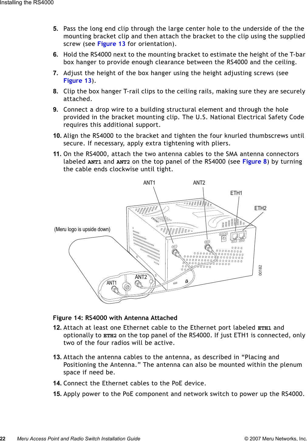
>
AP150R2 User Manual
>
User Manual
Contents
1.
User Manual
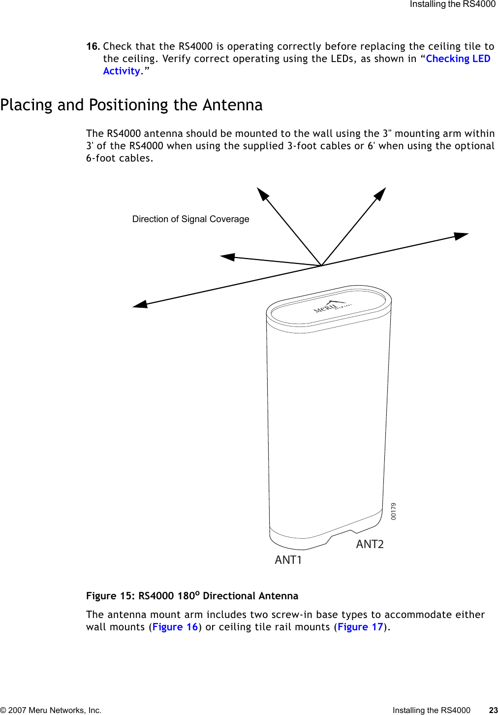
2.
User Manual update
User Manual
Navigation menu
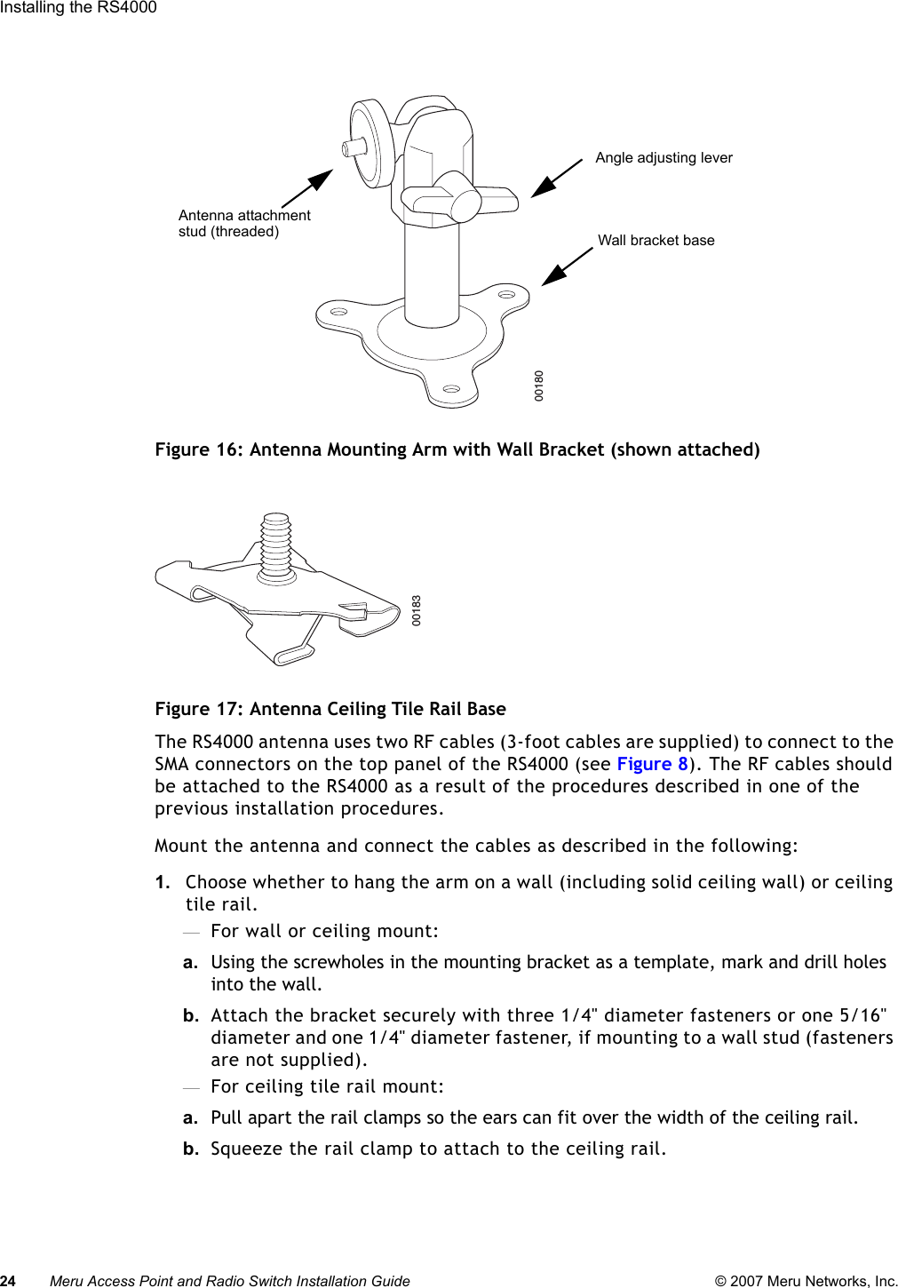
Upload a User Manual
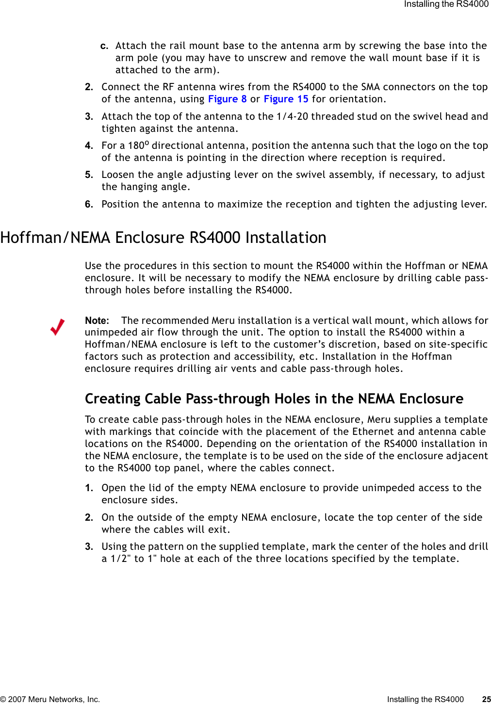
Namespaces
Wiki Guide
HTML
PDF
Info
Views
User Manual
Discussion / Help
Navigation