Meru Networks AP150R2 Dual Radio WLAN Access Point User Manual AP Install
Meru Networks Inc. Dual Radio WLAN Access Point AP Install
Contents
- 1. User Manual
- 2. User Manual update
User Manual

Meru Access Point and
Radio Switch
Installation Guide
Copyright © Meru Networks, Inc., 2003–2007. All rights reserved.
Other names and brands may be claimed as the property of others.
Document Number: 882-70034 Rev. A
© 2007 Meru Networks, Inc. Contents iii
Contents
About This Guide . . . . . . . . . . . . . . . . . . . . . . .ix
Audience . . . . . . . . . . . . . . . . . . . . . . . . . ix
In This Guide. . . . . . . . . . . . . . . . . . . . . . . . ix
Other Sources of Information . . . . . . . . . . . . . . . . . . x
Meru Publications . . . . . . . . . . . . . . . . . . . . . x
External References . . . . . . . . . . . . . . . . . . . . x
Typographic Conventions . . . . . . . . . . . . . . . . . . . x
Contacting Meru . . . . . . . . . . . . . . . . . . . . . . xi
Customer Services and Support . . . . . . . . . . . . . . . . xi
Chapter 1
Meru Access Points and Radio Switch . . . . . . . . . . . . . 1
Introducing the Radio Switch RS4000 . . . . . . . . . . . . . . . 1
RS4000 Hardware Features and Specifications . . . . . . . . . . . 3
Meru Access Point Features. . . . . . . . . . . . . . . . . . . 5
Introducing the Meru Access Point AP200 Series . . . . . . . . . . 5
Introducing the Meru Access Point AP150 Series . . . . . . . . . . 6
Chapter 2
Installing the RS4000 . . . . . . . . . . . . . . . . . . . . . 9
Safety Precautions . . . . . . . . . . . . . . . . . . . . . . 9
Unpacking the RS4000 . . . . . . . . . . . . . . . . . . . . 9
Installation Requirements . . . . . . . . . . . . . . . . . . . 10
About an Hoffman/NEMA Enclosure Installation . . . . . . . . . . 12
Optimum Antenna Positioning and Placement . . . . . . . . . . . 13
Installing the RS4000 . . . . . . . . . . . . . . . . . . . . . 14
Mounting the RS4000 . . . . . . . . . . . . . . . . . . . . 14
Placing and Positioning the Antenna . . . . . . . . . . . . . . 23
Hoffman/NEMA Enclosure RS4000 Installation . . . . . . . . . . . 25
Where to Go From Here . . . . . . . . . . . . . . . . . . . . 27
Checking LED Activity. . . . . . . . . . . . . . . . . . . . . 28
RS4000 Status LEDs . . . . . . . . . . . . . . . . . . . . 28
Chapter 3
Installing the AP200 . . . . . . . . . . . . . . . . . . . . 31
Safety Precautions . . . . . . . . . . . . . . . . . . . . . . 31
Unpacking the AP200 . . . . . . . . . . . . . . . . . . . . . 31
Installation Requirements . . . . . . . . . . . . . . . . . . . 32
Installing the Access Points . . . . . . . . . . . . . . . . . . . 34
Selecting a Location . . . . . . . . . . . . . . . . . . . . 34
Attaching the AP200 Antennas . . . . . . . . . . . . . . . . 35
iv Meru Access Point and Radio Switch Installation Guide © 2007 Meru Networks, Inc.
Mounting the Access Point . . . . . . . . . . . . . . . . . 35
Where to Go From Here . . . . . . . . . . . . . . . . . . . 43
Checking LED Activity . . . . . . . . . . . . . . . . . . . . 43
Ethernet Connector LEDs . . . . . . . . . . . . . . . . . . 43
AP200 Status LEDs . . . . . . . . . . . . . . . . . . . . 44
Chapter 4
Installing the AP150 . . . . . . . . . . . . . . . . . . . . . 47
Safety Precautions . . . . . . . . . . . . . . . . . . . . . 47
Unpacking the AP150 . . . . . . . . . . . . . . . . . . . . 47
Installation Requirements. . . . . . . . . . . . . . . . . . . 48
Installing the Access Points . . . . . . . . . . . . . . . . . . 50
Selecting a Location . . . . . . . . . . . . . . . . . . . 50
Attaching the AP150 Antennas . . . . . . . . . . . . . . . . 51
Mounting the Access Point . . . . . . . . . . . . . . . . . 51
Where to Go From Here . . . . . . . . . . . . . . . . . . . 57
Checking LED Activity . . . . . . . . . . . . . . . . . . . . 58
AP150 Status LEDs . . . . . . . . . . . . . . . . . . . . 58
Appendix A
Specifications . . . . . . . . . . . . . . . . . . . . . . . . 61
Wireless Interface . . . . . . . . . . . . . . . . . . . . . 61
Ethernet Interface . . . . . . . . . . . . . . . . . . . . . 62
Physical . . . . . . . . . . . . . . . . . . . . . . . . . 62
Appendix B
Regulatory Information . . . . . . . . . . . . . . . . . . . 63
USA . . . . . . . . . . . . . . . . . . . . . . . . . . 63
Underwriters Laboratories . . . . . . . . . . . . . . . . . 63
FCC Radiation Exposure Statement . . . . . . . . . . . . . . 64
Radio Frequency Interference Requirements . . . . . . . . . . . 64
Canada. Industry Canada (IC) . . . . . . . . . . . . . . . . . 65
Europe—EU Declaration of Conformity and Restrictions . . . . . . . . 67
IEEE 802.11a Restrictions. . . . . . . . . . . . . . . . . . 69
EEE 802.11b/g Restrictions . . . . . . . . . . . . . . . . . 70
Japan. . . . . . . . . . . . . . . . . . . . . . . . . . 70
Manufacturing Information . . . . . . . . . . . . . . . . . . 71
Appendix C
Channels . . . . . . . . . . . . . . . . . . . . . . . . . . 73
Channels . . . . . . . . . . . . . . . . . . . . . . . . 73
IEEE 802.11a . . . . . . . . . . . . . . . . . . . . . . 73
IEEE 802.11b/g . . . . . . . . . . . . . . . . . . . . . 75
Appendix D
Mounting Bracket Stencils . . . . . . . . . . . . . . . . . . 77
AP150 Mounting Bracket Stencil . . . . . . . . . . . . . . . . 77
© 2007 Meru Networks, Inc. List of Figures v
List of Figures
Figure 1 Radio Switch RS4000 .............................................................. 2
Figure 2 Access Point AP200 ............................................................... 6
Figure 3 Access Point AP150 ............................................................... 7
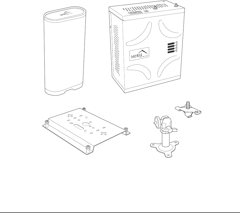
Figure 4 RS4000 Package Contents ........................................................ 10
Figure 5 Open NEMA Box Showing Mounting Holes ...................................... 13
Figure 6 Bracket Attached to RS4000 ..................................................... 15
Figure 7 RS4000 Bracket Mounting ........................................................ 16
Figure 8 RS4000 with Antenna Attached ................................................. 17
Figure 9 Mounting the RS4000 Below a Suspended Ceiling Rail ....................... 18
Figure 10 RS4000 with Antenna Attached ................................................ 19
Figure 11 Mounting the RS4000 Above a Suspended Ceiling ........................... 20
Figure 12 Box Hanger Mounting Bracket Holes .......................................... 21
Figure 13 Attaching the Mounting Bracket to the Box Hanger ........................ 21
Figure 14 RS4000 with Antenna Attached ................................................ 22
Figure 15 RS4000 180o Directional Antenna ............................................. 23
Figure 16 Antenna Mounting Arm with Wall Bracket (shown attached) ............. 24
Figure 17 Antenna Ceiling Tile Rail Base ................................................. 24
Figure 18 RS4000 and Antenna Installed in NEMA Enclosure .......................... 26
Figure 19 RS4000 Status LEDs .............................................................. 28
Figure 20 AP200 Mounting Bracket ........................................................ 32
Figure 21 AP200 Antenna Connection ..................................................... 36
Figure 22 AP200 Connector Panel ......................................................... 36
Figure 23 AP200 Bracket .................................................................... 37
Figure 24 Aligning the AP200 with the Bracket ......................................... 38
Figure 25 Sliding the AP200 into the Bracket ............................................ 38
Figure 26 Mounting the AP200 to a Suspended Ceiling Rail ........................... 39
Figure 27 Mounting the AP200 Above a Suspended Ceiling ............................ 41
Figure 28 Box Hanger Mounting Bracket Holes .......................................... 41
Figure 29 Attaching the Mounting Bracket to the Box Hanger ........................ 42
Figure 30 RJ-45 LEDs ........................................................................ 43
Figure 31 AP200 Status LEDs ............................................................... 44
Figure 32 AP150 with Mounting Bracket .................................................. 48
Figure 33 AP150 Antenna Connection ..................................................... 52
Figure 34 AP150 Connector Panel ......................................................... 52
Figure 35 AP150 Bracket .................................................................... 54
Figure 36 Aligning the AP150 with the Bracket ......................................... 55
Figure 37 Mounting the AP150 to a Suspended Ceiling Rail ........................... 56
Figure 38 AP150 Status LEDs ............................................................... 58
vi Meru Access Point and Radio Switch Installation Guide © 2007 Meru Networks, Inc.
© 2007 Meru Networks, Inc. List of Tables vii
List of Tables
Table 1 RS4000 Hardware Features .............................................. 3
Table 2 RS4000 Installation Tools ................................................ 12
Table 3 RS4000 LED Descriptions ................................................. 29
Table 4 AP200 Installation Items ................................................. 33
Table 5 AP200 Installation Tools ................................................. 34
Table 6 AP200 LED Descriptions .................................................. 45
Table 7 AP200 Controller Status Information ................................... 45
Table 8 AP150 Installation Items ................................................. 49
Table 9 AP150 Installation Tools ................................................. 50
Table 10 AP150 LED Descriptions ................................................. 59
Table 11 Wireless Interface Specifications ..................................... 61
Table 12 IEEE 802.11a Channels .................................................. 73
Table 13 IEEE 802.11b/g Channels ............................................... 75
viii Meru Access Point and Radio Switch Installation Guide © 2007 Meru Networks, Inc.

© 2007 Meru Networks, Inc. About This Guide ix
About This Guide
This guide describes the features and provides installation instructions for the Meru
Access Points, which includes the AP200 and AP150 models, and the Radio Switch
RS4000. The term access point is used interchangeably throughout this document to
apply to any model when there are no differences among the models.
Audience
This guide is intended for persons installing the Meru Wireless LAN System Access
Point (AP) and Radio Switches.
In This Guide
This guide includes the following chapters:
zChapter 1, “Meru Access Points and Radio Switch”
zChapter 2, “Installing the RS4000”
zChapter 3, “Installing the AP200”
zChapter 4, “Installing the AP150”
zAppendix A, “Specifications”
zAppendix B, “Regulatory Information”
zAppendix C, “Channels”
zAppendix D, “Mounting Bracket Stencils”

© 2007 Meru Networks, Inc. About This Guide x
Other Sources of Information
Additional information is available in the following Meru publications, Web site, and
external references.
Meru Publications
zMeru System Director Release Notes
zMeru System Director Getting Started Guide
zMeru Controller Installation Guide
zMeru System Director Command Reference
zMeru System Director Configuration Guide
External References
zStevens, W. R. 1994. TCP/IP Illustrated, Volume 1, The Protocols. Addison-Wesley,
Reading, Mass.
zGast, M.S. 2002. 802.11 Wireless Networks, The Definitive Guide. O’Reilly and
Associates, Sebastopol, Calif.
Typographic Conventions
This document uses the following typographic conventions to help you locate and
identify information:
Note:
Provides extra information, tips, and hints regarding the topic.
Caution!
Identifies important information about actions that could result in
damage to or loss of data, or could cause the application to behave in
unexpected ways.
Warning!
Identifies critical information about actions that could result in
equipment failure or bodily harm.

© 2007 Meru Networks, Inc. About This Guide xi
Contacting Meru
You can visit Meru Networks, Inc. on the Internet at this URL:
http://www.merunetworks.com
Customer Services and Support
For assistance, contact Meru Customer Services and Support 24 hours a day at
+1-888-637-8952 (+1-888-Meru-WLA(N)) or +1-408-215-5305. Email can be sent to
support@merunetworks.com.
Meru Networks, Inc. Customer Services and Support provide end users and channel
partners with the following:
zTelephone technical support
zSoftware update support
zSpare parts and repair service
RMA Procedures
Contact Meru Customer Services and Support for a Return Material Authorization
(RMA) for any Meru equipment.
Please have the following available when making a call:
zCompany and contact information
zEquipment model and serial numbers
zMeru software release and revision numbers (for example, 3.0.0-35)
zA description of the symptoms the problem is manifesting
zNetwork configuration
© 2007 Meru Networks, Inc. About This Guide xii
© 2007 Meru Networks, Inc. Meru Access Points and Radio Switch 1
Chapter 1
Meru Access Points and Radio Switch
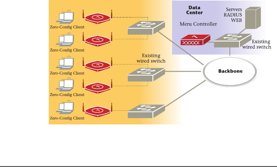
Meru Access Points and Radio Switches contain radio devices that communicate with
the Meru Controller and form the wireless LAN (WLAN). The Meru Controller, Radio
Switches, and Access Points connect to the site’s wired LAN through wired switches.
Wireless clients associate with the Radio Switches and Access Points as they roam
throughout the WLAN. As such, the Meru Wireless LAN System is an extension of the
wired LAN, providing the wireless benefits of client mobility, enhanced access, and
dynamic network configuration.
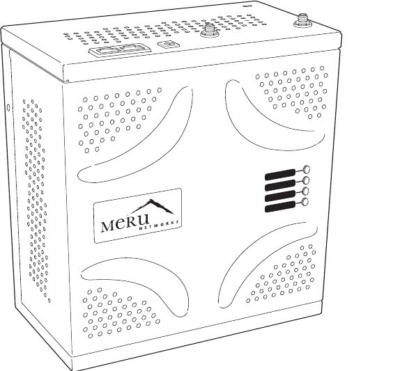
Introducing the Radio Switch RS4000
The Radio Switch RS4000 enables high-capacity enterprise-class wireless LAN connec-
tivity with full support of standard 802.11 security and network management
features. Each RS4000 contains four 802.11 radios (two 802.11b/g, two 802.11a) for
high data and voice throughput – an essential requirement for high user-density envi-
ronments with several simultaneous users. Classrooms and convention halls are
typical deployment applications of the Radio Switch. Deploying the Radio Switch is
Meru AP
© 2007 Meru Networks, Inc. Meru Access Points and Radio Switch 2
easy— as with wireless access points, the Radio Switch can be installed wherever
wireless coverage is needed. For large buildings with multiple rooms and floors, more
than one Radio Switch can be installed to cover the desired area. Wireless users can
seamlessly roam from one Radio Switch to another, getting high-capacity WLAN
access throughout the wireless enterprise enabled with multiple Radio Switches. The
RS4000 also balances radio traffic across its RF channels and resolves contention
within each RF channel such that users receive a switched wireless experience with
dedicated bandwidth to execute a variety of applications ranging from web browsing
and VoIP mobility to multimedia streaming.
The RS4000 ships with either a high-gain omni-directional indoor antenna or a 180-
degree directional indoor antenna that aggregates and layers radio transmissions
from each of the built-in radios. The antenna can broadcast every channel available
to blanket the area around the Radio Switch, yet avoid interference and contention.
This simplifies deployment efforts by eliminating the need for additional antennas
for each radio. More importantly, RF channel planning efforts are greatly simplified.
Using the RS4000, wireless users experience the benefits of switching technology on
Wi-Fi—dedicated bandwidth, traffic separation, and multi-service network support.
The RS4000 can be deployed with up to two 802.11b/g and two 802.11a channels
active on the radio interfaces. The 802.11b/g channels must be separated by a
minimum of 8 channels (for example, channels 1 and 9), so the recommended set is
channels 1 and 11, typically. The 802.11a channels must be separated by a minimum
of 80MHz/16 channels for best performance (for example, channels 36 and 52).
Figure 1: Radio Switch RS4000
POWER
RADIO I
RADIO II
ETHERNET
00178
© 2007 Meru Networks, Inc. Meru Access Points and Radio Switch 3
RS4000 Hardware Features and Specifications
The RS4000 has four 802.11 radios (two 802.11a and two 802.11bg) that transmit and
receive simultaneously on four different channels to increase the total available
wireless bandwidth at a given area. The RS4000 connects to the LAN using one 10/100
Mbps Ethernet connection for each radio pair. The RS4000 is powered using two IEEE
802.3af POE connections, each with 15W power.
.
The RS4000 works in conjunction with a wideband RF combination omni directional
(WRC/OD) indoor antenna or a 180-degree directional indoor antenna. Only one
antenna is needed for simultaneous operation of all radios of an RS4000 in both the
2.4GHz and 5GHz bands. The antenna must be connected to the Radio Switch using
any one of the low-loss antenna cables provided in the antenna packaging.
The following table lists the key hardware features of the RS4000.
Note:
PoE must be provided on the first Ethernet connector (ETH1); the antenna
cannot operate correctly without that power source. Power to the second
Ethernet connector (ETH2 ) is optional; if not connected, two of the
radios will not operate.
Table 1: RS4000 Hardware Features
Feature Description
802.11 Connectivity Two 802.11b/g radios (2.4GHz)
Two 802.11a radios (5 GHz)
Ethernet Connectivity Two auto-sensing 10/100 Mbps ports, one
for each radio pair
Power
Provided by two 802.3af POE connec-
tions, one for each radio pair (15W per
connector)
LEDs Power, Radio Activity, and Ethernet
Activity LEDs per radio
Dimensions 9.5" x 8.5" x 3.875"

© 2007 Meru Networks, Inc. Meru Access Points and Radio Switch 4
Mounting Options
RS4000 has mounting brackets available
for:
zCeiling Mount
zWall Mount
zInside NEMA Enclosures (Hoffman,
etc.)
Antenna
The RS4000 ships with either of these
antennas:
zWideband RF Combination/Omni-
Directional (WRC/OD) Antenna. 5dBi
gain. Indoor use.
z180-degree directional indoor antenna
Antenna Cables
3’ low-loss cables (default option)
6’ and plenum-rated cables (available
option)
Table 1: RS4000 Hardware Features
Feature Description

© 2007 Meru Networks, Inc. Meru Access Points and Radio Switch 5
Meru Access Point Features
Meru Access Points provide the following features:
zWi-Fi Certified Tri-mode Access Point Delivers Exceptional Performance
A key component of the Meru Wireless LAN System, Meru Access Points deliver
unsurpassed Wi-Fi performance in conjunction with Meru Controllers.
Representing a shift to the fourth generation WLAN architecture using
coordinated intelligent APs at the edge, the Meru Wireless LAN System delivers
toll quality voice over Wi-Fi, a ten-fold increase in client density, intelligent load
balancing, and lowest total cost of ownership.
zThe Only Solution to Deliver a Large Scale Voice and Data Wireless Access
Embedded Wi-Fi in laptops are almost ubiquitous and other mobile devices aren't
far behind. In addition, with emerging dual mode Wi-Fi/cellular phones the
number of clients in your enterprise is going to increase exponentially in only a
few short years. Deploy a system that is designed to deal with high densities of
voice and data clients, without sacrificing performance and that works with any
standard Wi-Fi certified client.
zTri-mode Access Point Provides Investment Protection
Enterprise applications and user density continue to increase. Tri-mode
802.11a/b/g clients are now commonplace in laptops. Ensure your network
supports the full breadth of wireless LAN clients with Meru Access Points.
—Dual 802.11b/g and 802.11a software programmable radios
—Simultaneously support 802.11b, 802.11g and 802.11a clients
Introducing the Meru Access Point AP200 Series
The Meru Access Point AP200 series provides two models that conform to the speci-
fications provided by the IEEE 802.11a and 802.11g protocols and provide backward
compatibility for the 802.11b protocol. An AP200 works with most standard Wi-Fi
clients.
zThe AP201 houses a single 802.11a/b/g radio device
zThe AP208 supports a maximum of two radio devices that can simultaneously run
two protocols (802.11b, g or b/g on interface 1 and 802.11a on interface 2).
Alternately the second radio can be configured to run as an RF monitor to the Meru
Controller, providing real-time status of RF activity to optimize the wireless
network.
The Meru Access Point AP200 series (referred hereafter as the AP200, unless specif-
ically referring to the AP201 or AP208) is housed in a metal case with a plastic remov-
able cover. As such, it can be used for plenum installations when the plastic cover is
removed.
© 2007 Meru Networks, Inc. Meru Access Points and Radio Switch 6
Figure 2: Access Point AP200
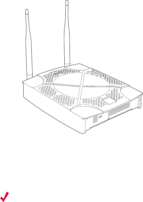
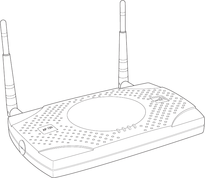
Introducing the Meru Access Point AP150 Series
The AP150 has two 802.11 radios for simultaneous 802.11a and 802.11b/g WLAN
access. It is an ideal option for enterprise-wide data-only WLAN implementations and
small-sized converged data and voice WLAN implementations. The AP150 works in
conjunction with Meru Controller products and can be easily integrated into existing
Layer 2 and Layer 3 wired network environments to provide enterprise-grade Wi-Fi
access with multi-layered security options, basic VoWLAN support, centralized
configuration, troubleshooting tools, remote management and RF visualization capa-
bilities.
The Meru Access Point AP150 supplies the following features:
zDual 802.11b/g and 802.11a radios
zSimultaneously support for 802.11b, 802.11g, and 802.11a clients
zContention Management for high density of data clients
zBasic VoWLAN QoS support for small density of voice clients
zMultiple ESSIDs with individual security policies to ensure separation of different
user groups or dynamic VLAN assignment per user based on RADIUS credentials
AP200
00109
Note:
Meru Access Point AP150 models may have different revisions, but function-
ally they are the same, and all are referred to as the AP150 series. Hereafter
in this document, all AP150 series models are referred to as the AP150.
© 2007 Meru Networks, Inc. Meru Access Points and Radio Switch 7
zZero configuration required at the access point; the installation procedure is a
simple plug-n-play
zAutomatic AP discovery, configuration
zIntelligent load balancing of clients
zLayer 2 or 3 connectivity for flexible deployment options
zLocking mechanism secures access point when mounted in public areas
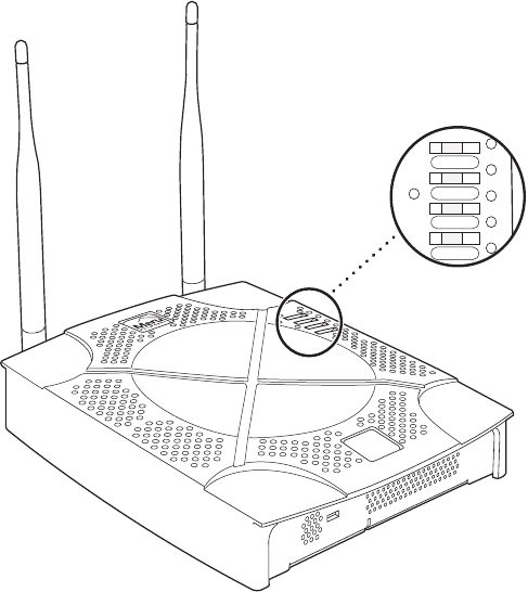
Figure 3: Access Point AP150
PWR
LAN
RADIO2
RADIO1
00175
© 2007 Meru Networks, Inc. Meru Access Points and Radio Switch 8

© 2007 Meru Networks, Inc. Installing the RS4000 9
Chapter 2
Installing the RS4000
This chapter describes how to physically install the Meru Radio Switch RS4000. It
contains the following sections:
zSafety Precautions
zUnpacking the RS4000
zInstallation Requirements
zInstalling the RS4000
zWhere to Go From Here
zChecking LED Activity
Safety Precautions
IMPORTANT—Read and follow the instructions in Appendix B, “Regulatory Informa-
tion” on page 63 before installing and operating this product.
Unpacking the RS4000
Confirm that the RS4000 shipping package contains the following items:
zRS4000
z180-degree directional antenna or omni-directional antenna
zTwo 3-foot antenna cables
zOne 3-inch mounting arm (includes wall mount base and ceiling rail base)
zMounting bracket
zAdditional options can be purchased, such as a NEMA box mounting bracket and
6-foot antenna cables
10 Meru Access Point and Radio Switch Installation Guide © 2007 Meru Networks, Inc.
Installation Requirements
Figure 4: RS4000 Package Contents
Installation Requirements
The following prerequisites and system requirements must be met:
z2 IEEE 802.3 PoE connections— one to each Ethernet port, yielding a maximum
power specification of 11W per port, 22W total for the RS4000
zNetwork switch for connecting all networking components
The RS4000 requires a location that meets the following:
zA location to mount the antenna within 6’ of the RS4000 and with relatively
unobstructed access to the client stations
zPower over Ethernet (PoE) connection to the network switch servicing the RS4000
POWER
RADIO I
RADIO II
ETHERNET
Wall mounting bracket 3-inch mounting arm with
wall mounting base
Ceiling rail
mounting
base
00193
RS4000Antenna

Installation Requirements
© 2007 Meru Networks, Inc. Installing the RS4000 11
The RS4000 obtains power from 802.3af standard Power over Ethernet (PoE)-compat-
ible network switch or PoE power injector installed between the switch and the
RS4000. At least one PoE connection must be connected.
Select a location with minimal physical obstructions between the RS4000 antenna
and the wireless stations. In many cases, mounting the RS4000 antenna on the wall
near the ceiling provides the least obstructed communications path.
Most installations receive the best coverage using the following guidelines:
zDo not install the antenna near metal objects, such as heating ducts, metal doors,
or electric service panels.
zRelative to the ground, orient the antenna up or down, not sideways.
The RS4000 is only intended for installation in Environment A as defined in IEEE
802.3af. All interconnected equipment must be contained within the same building,
including the interconnected equipment's associated LAN connection.
Note:
The previous guidelines are general guidelines. Each site has its own unique
environment. Place antenna accordingly.

12 Meru Access Point and Radio Switch Installation Guide © 2007 Meru Networks, Inc.
Installation Requirements
You need the tools listed in Tab le 2 .
Table 2: RS4000 Installation Tools
About an Hoffman/NEMA Enclosure Installation
The recommended RS4000 installation is a wall mount, but if necessary the RS4000
can be housed inside a protective NEMA or Hoffman box that is manufactured with
external corner tabs for standard wall mounting, above or below a ceiling. When
installing in the Hoffman/NEMA box, the RS4000 attaches to an optional
Hoffman/NEMA box mounting plate, which replaces the standard wall mount bracket.
Meru leaves the placement and orientation of the Hoffman/NEMA enclosure to the
customer. It will be necessary to drill holes through the plastic NEMA enclosure with
a Meru-provided template to enable the antenna and Ethernet cabling to exit the
enclosure. Instructions for performing this task are provided in the section “Creating
Installation Type Tools Required
Vertical mounting over a wall
stud
zDrill
z1/8"drill bit
zScrewdriver
z(Optional) Pliers
Vertical mounting on sheetrock
zDrill
z3/16" drill bit
zScrewdriver
z(Optional) Pliers
Horizontal mounting below a
hanging ceiling
zTwo caddy fasteners
zTwo plastic spacers
zTwo keps nuts (with attached lock washer)
zMounting bracket
Mounting above a ceiling tile
zTwo T-ra i l cl i p s
zOne T-box hanger
zOne bracket mounting clip
zMounting bracket
Caution!
This method of mounting has not been evaluated by Underwriters
Laboratories.
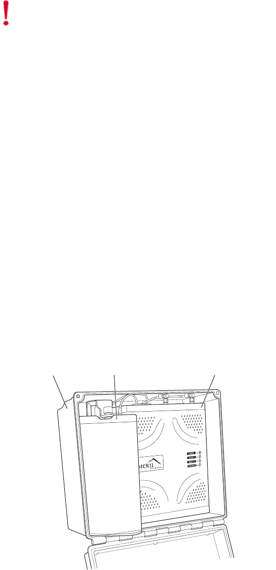
Installation Requirements
© 2007 Meru Networks, Inc. Installing the RS4000 13
Cable Pass-through Holes in the NEMA Enclosure” on page 25. To install in the
Hoffman/NEMA Enclosure, see the section “Hoffman/NEMA Enclosure RS4000 Instal-
lation” on page 25.
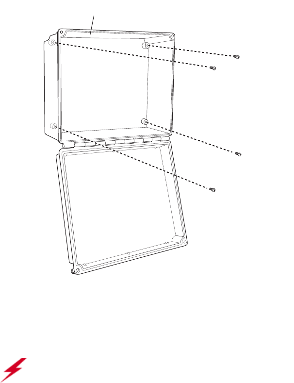
Figure 5: Open NEMA Box Showing Mounting Holes
Optimum Antenna Positioning and Placement
00187
NEMA box
Attach to wall with 4 screw
s
Warning!
Inside antennas must be positioned to observe minimum separation of 20
cm. (~ 8 in.) from all users and bystanders. For the protection of personnel working
in the vicinity of inside (downlink) antennas, the following guidelines for minimum
distances between the human body and the antenna must be observed.
The installation of the indoor antenna must be such that, under normal conditions,
all personnel cannot come within 20 cm. (~ 8.0 in.) from any inside antenna.
Exceeding this minimum separation will ensure that the employee or bystander does
not receive RF-exposure beyond the Maximum Permissible Exposure according to FCC
CFR 47, section 1.1310 i.e. limits for General Population/Uncontrolled Exposure.

14 Meru Access Point and Radio Switch Installation Guide © 2007 Meru Networks, Inc.
Installing the RS4000
Installing the RS4000
Mounting the RS4000
You can mount the RS400 in the following ways:
zWall Mounting the RS4000
zMounting Below a Suspended Ceiling
zMounting Above a Suspended Ceiling
zPlacing and Positioning the Antenna
zHoffman/NEMA Enclosure RS4000 Installation
Wall Mounting the RS4000
The RS4000 can be mounted to any type of solid wall (including ceiling walls) using
the supplied wall mount bracket. The bracket also allows for junction box mounting.
Note:
The RS4000 has a security cable slot so you can secure the RS4000 with a
standard security cable (for example, Kensington cable locks), such as are used to
secure laptop computers.
To wall mount an RS4000:
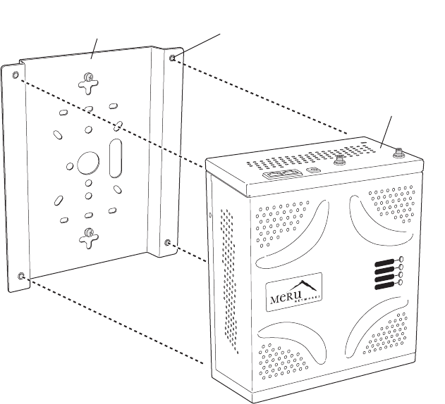
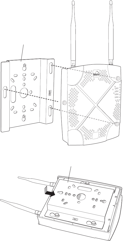
1. Remove the bracket from back side the RS4000, if it is attached, by unscrewing
each of the 4 knurled thumbscrews (see Figure 6).
Installing the RS4000
© 2007 Meru Networks, Inc. Installing the RS4000 15
Figure 6: Bracket Attached to RS4000
2. Choose the location on the wall where the RS4000 will be mounted. The RS4000
can be oriented in any direction, but it is probably more convenient if the SMA
antenna mounts are at the top. This orientation is more convenient for reading
LED status.
3. Using the bracket holes as a template, mark the location on the wall for the two
RS4000 bracket mounting screws. They are placed 5 25/32" (147mm) apart,
center-to-center, one above the other. If you are not using plastic wall anchors,
you must center the mounting screws on a wall stud.
4. Drill holes at the locations you marked:
—3/16-inch holes if you are using plastic anchors
—1/8-inch holes if you are using only the screws
5. If you are using plastic anchors, install them in the holes.
Note:
The RS4000 mounting bracket provides holes to accommodate many types of
common installations such as over a junction box, etc. This procedure describes only
the standard wall mount.
16 Meru Access Point and Radio Switch Installation Guide © 2007 Meru Networks, Inc.
Installing the RS4000
6. Screw in the screws most of the way, so that the screw head is about 1/16 of an
inch from the wall.
7. Mount the bracket on the screws, placing the circular portion of the keyhole
mounts over the screw heads and sliding the bracket down.
Figure 7: RS4000 Bracket Mounting
8. Tighten the bracket captive screws to secure the RS4000 to the bracket.
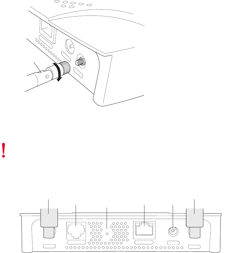
9. On the RS4000, attach the two antenna cables to the SMA antenna connectors
labeled ANT1 and ANT2 on the top panel of the RS4000 (see Figure 8) by turning
the cable ends clockwise until tight.
POWER
RADIO I
RADIO II
ETHERNET
00186
Wall mounting bracket
(attached to wall)
RS4000
Captive screws (4)

Installing the RS4000
© 2007 Meru Networks, Inc. Installing the RS4000 17
Figure 8: RS4000 with Antenna Attached
10. Attach at least one Ethernet cable to the Ethernet port labeled ETH1 and
optionally to ETH2 on the top panel of the RS4000. If just ETH1 is connected, only
two of the four radios will be active.
11. Align the RS4000 to the bracket (against the wall) and tighten the four knurled
thumbscrews until secure. If necessary, apply extra tightening with pliers.
12. Attach the antenna cables to the antenna, as described in “Placing and
Positioning the Antenna.”
13. Connect the two Ethernet cables to the PoE device.
14. Apply power to the PoE component and network switch to power up the RS4000.
15. Verify correct operating using the LEDs, as shown in “Checking LED Activity.”
K
00182
ANT1 ANT2
ETH1
ETH2
ANT1
ANT2
(Meru logo is upside down)
18 Meru Access Point and Radio Switch Installation Guide © 2007 Meru Networks, Inc.
Installing the RS4000
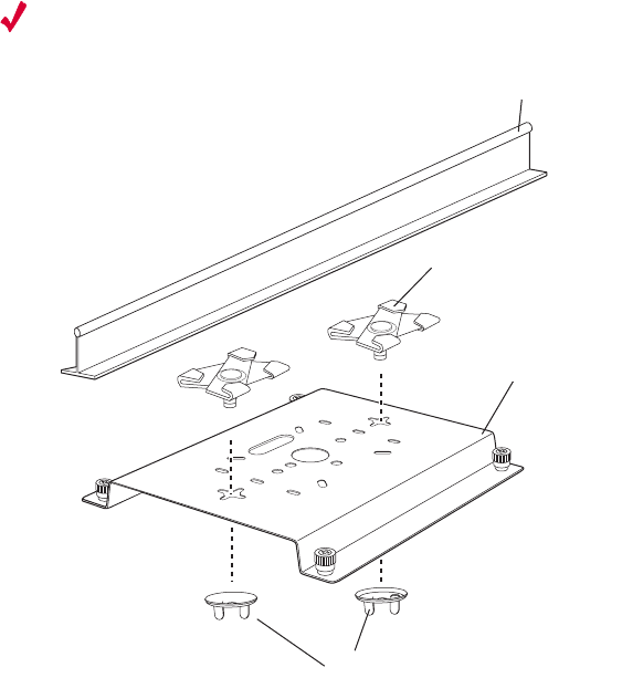
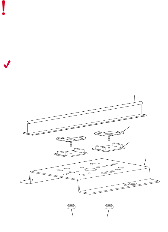
Mounting Below a Suspended Ceiling
The optional suspended ceiling mounting kit allows the RS4000 mounting bracket to
attach to suspended ceiling T-rails (see Figure 9).
Note:
To comply with NEC code, attach a grounding wire to any of the screws used
to attach the RS4000 to the mounting bracket.
Figure 9: Mounting the RS4000 Below a Suspended Ceiling Rail
To mount an RS4000 below a suspended ceiling:
1. Determine the location on the ceiling rail where the RS4000 will be mounted and
remove the ceiling tiles.
2. Place each of the two caddy fasteners on the ceiling T-rail and twist to attach to
the rail.
3. Adjust the distance between the caddy fasteners by using the mounting bracket
holes as a guide.
4. Tighten the caddy fasteners in place using a standard screwdriver. Do not
overtighten.
5. Place each spacer on the caddy fastener stud. The spacer legs should contact the
ceiling T-rail.
6. Align the mounting bracket keyholes with the caddy fastener studs and slide the
RS4000 to the narrow end of the hole.
00189
Mounting brack
et
Ceiling tile fastener
Washers

Installing the RS4000
© 2007 Meru Networks, Inc. Installing the RS4000 19
7. Attach a keps nut to each caddy fastener stud and hand tighten. Do not
overtighten.
8. On the RS4000, attach the two antenna cables to the SMA antenna connectors
labeled ANT1 and ANT2 on the top panel of the RS4000 (see Figure 8) by turning
the cable ends clockwise until tight.
Figure 10: RS4000 with Antenna Attached
9. Attach at least one Ethernet cable to the Ethernet port labeled ETH1 and
optionally to ETH2 on the top panel of the RS4000. If just ETH1 is connected, only
two of the four radios will be active.
10. Align the RS4000 to the bracket and tighten the four knurled thumbscrews until
secure. If necessary, apply extra tightening with pliers.
11. Attach the antenna cables to the antenna, as described in “Placing and
Positioning the Antenna.”
12. Connect the two Ethernet cables to the PoE device.
13. Apply power to the PoE component and network switch to power up the RS4000.
14. Verify correct operating using the LEDs, as shown in “Checking LED Activity.”
K
00182
ANT1 ANT2
ETH1
ETH2
ANT1
ANT2
(Meru logo is upside down)
20 Meru Access Point and Radio Switch Installation Guide © 2007 Meru Networks, Inc.
Installing the RS4000
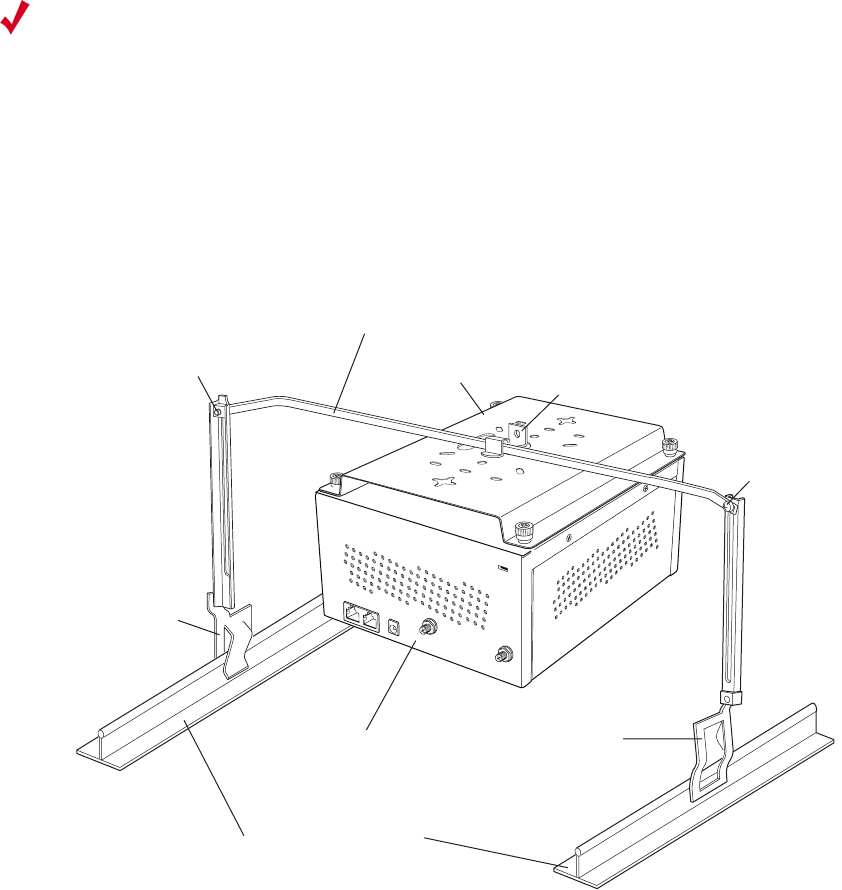
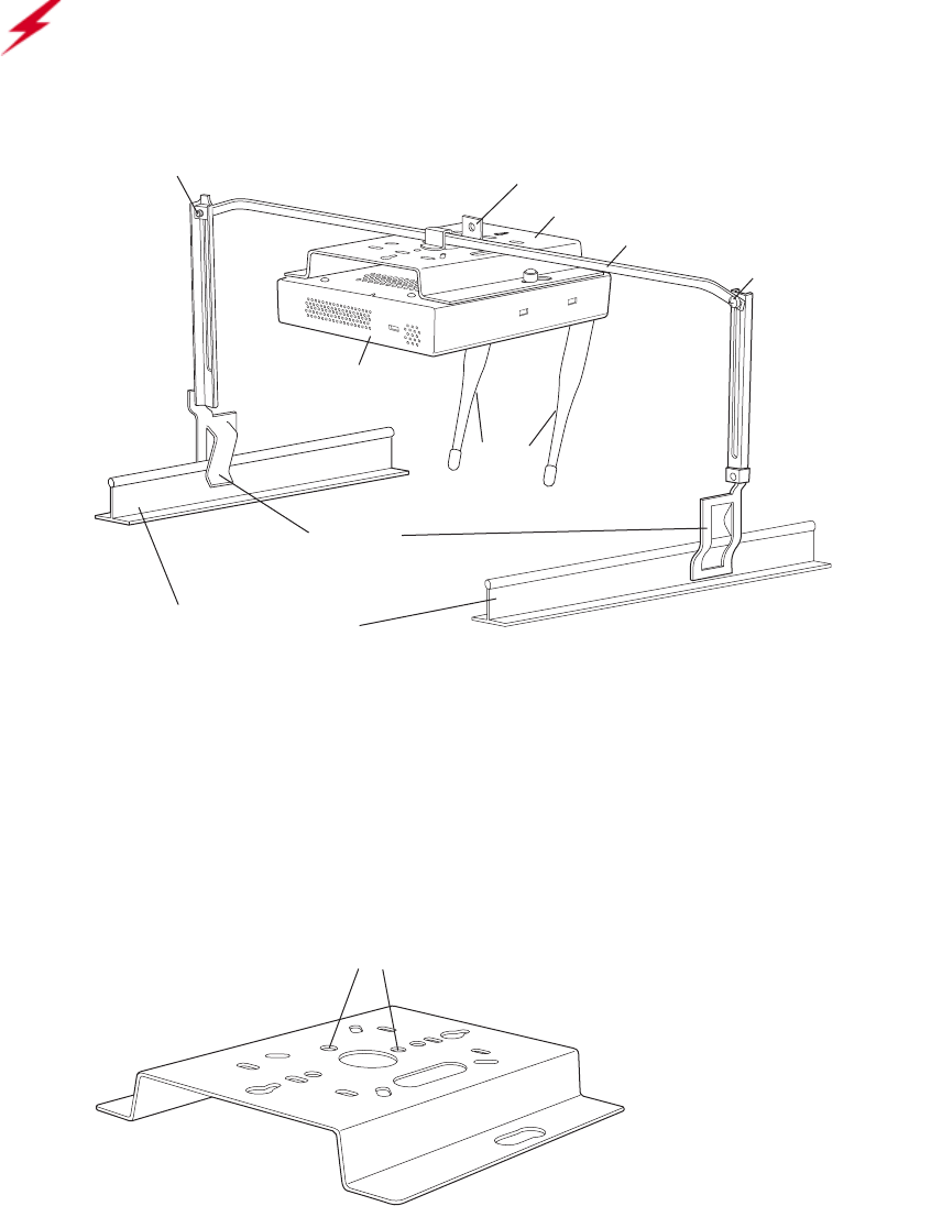
Mounting Above a Suspended Ceiling
The optional T-bar box hanger mounting kit allows the RS4000 to be mounted above
suspended ceiling T-rails (see Figure 11). The installation attaches the T-bar box
hanger to the ceiling rails using clips. The RS4000 attaches to the mounting bracket
that is attached to the T-bar box hanger.
Any Fast Ethernet (FE) cables installed in air-handling spaces should be suitable
under NEC Article 800.50 and marked accordingly for use in plenums and air-handling
spaces with regard to smoke propagation, such as CL2-P, CL3-P, MPP (Multi Purpose
Plenum), or CMP (Communications Plenum).
Figure 11: Mounting the RS4000 Above a Suspended Ceiling
To mount an RS4000 above suspended ceiling rails:
1. Determine the location on the ceiling rails where the RS4000 will be mounted and
remove the ceiling tile.
Note:
The RS4000 and its antenna meet the requirements for fire resistance and low
smoke-generating characteristics required by Section 300-22(C) of the National
Electrical Code (NEC) for installation in a building’s environmental air space.
Additonally, you must use Ethernet cable that meets the requirements for operating
in environmental air space (in accordance with Section 300-22(C) of the NEC).
00190
Bracket mounting clipMounting bracket
T-bar hanger
Height adjustment screw
Suspended ceiling T-rail
T-rail clip
T-rail clip
R
S
4000
Height
adjustment
screw
Installing the RS4000
© 2007 Meru Networks, Inc. Installing the RS4000 21
2. Unpack the T-bar hanger kit and unfold the legs of the T-bar hanger.
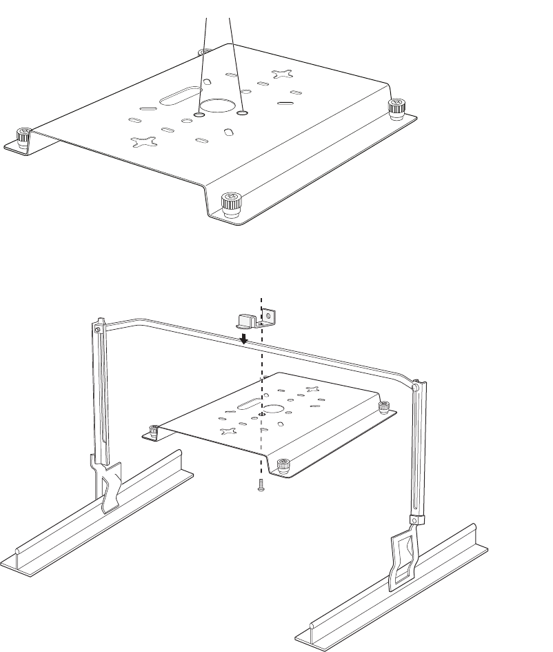
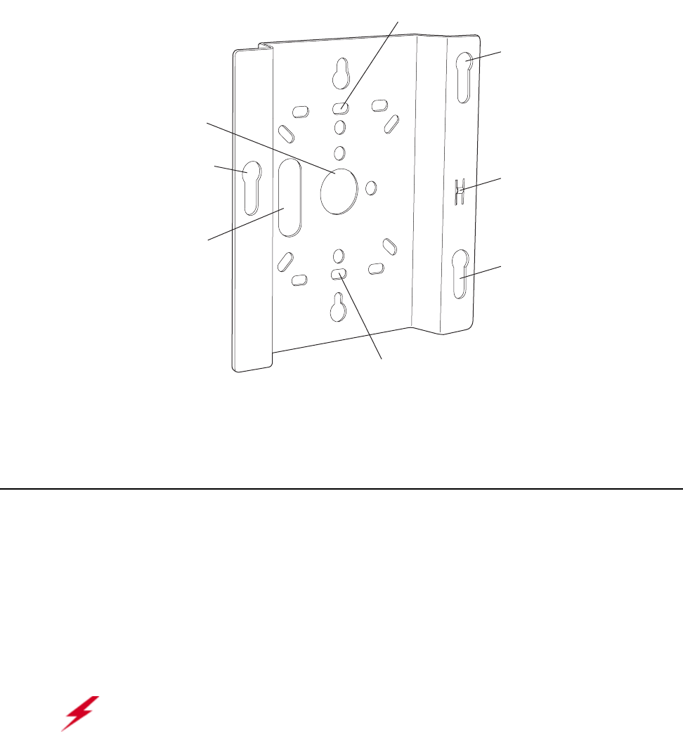
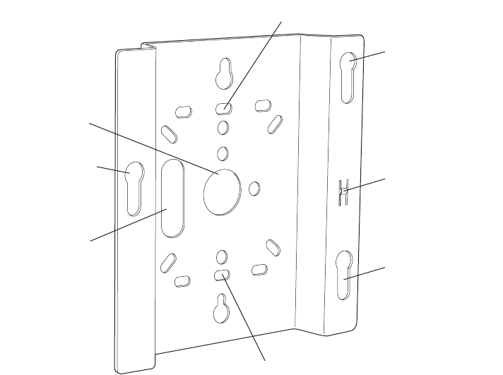
3. Locate the bracket mounting clip holes on the mounting bracket (see Figure 12).
One hole attaches the bracket perpendicular to the box hanger. The other mounts
the bracket parallel to the box hanger.
Figure 12: Box Hanger Mounting Bracket Holes
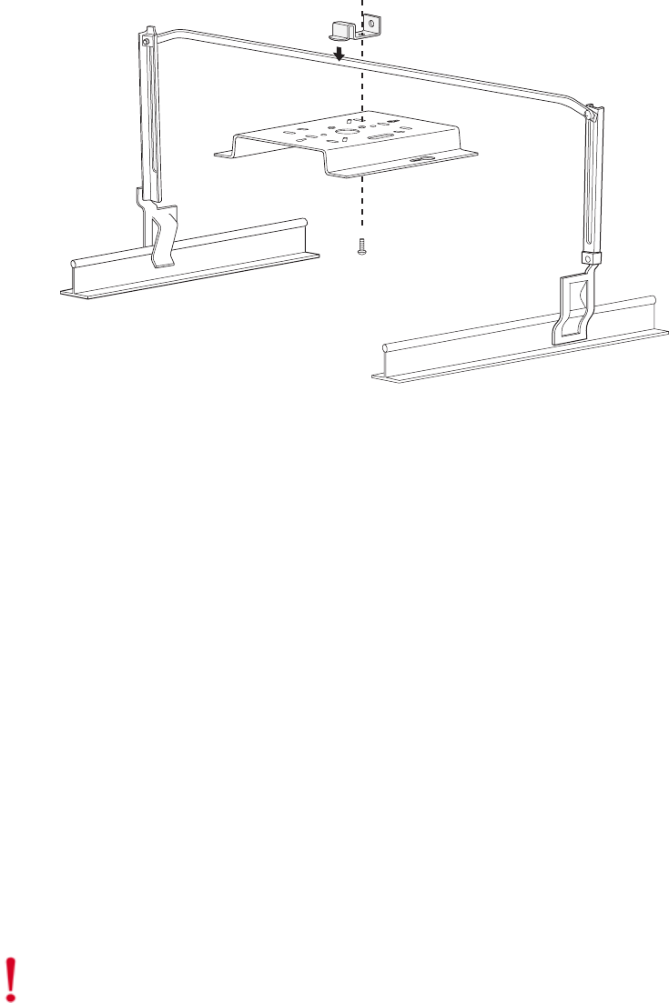
4. Attach the U-joint of the clip to the T-bar and snap in place (see Figure 13).
.
Figure 13: Attaching the Mounting Bracket to the Box Hanger
Mounting bracket holes
00191
00192
22 Meru Access Point and Radio Switch Installation Guide © 2007 Meru Networks, Inc.
Installing the RS4000
5. Pass the long end clip through the large center hole to the underside of the the
mounting bracket clip and then attach the bracket to the clip using the supplied
screw (see Figure 13 for orientation).
6. Hold the RS4000 next to the mounting bracket to estimate the height of the T-bar
box hanger to provide enough clearance between the RS4000 and the ceiling.
7. Adjust the height of the box hanger using the height adjusting screws (see
Figure 13).
8. Clip the box hanger T-rail clips to the ceiling rails, making sure they are securely
attached.
9. Connect a drop wire to a building structural element and through the hole
provided in the bracket mounting clip. The U.S. National Electrical Safety Code
requires this additional support.
10. Align the RS4000 to the bracket and tighten the four knurled thumbscrews until
secure. If necessary, apply extra tightening with pliers.
11. On the RS4000, attach the two antenna cables to the SMA antenna connectors
labeled ANT1 and ANT2 on the top panel of the RS4000 (see Figure 8) by turning
the cable ends clockwise until tight.
Figure 14: RS4000 with Antenna Attached
12. Attach at least one Ethernet cable to the Ethernet port labeled ETH1 and
optionally to ETH2 on the top panel of the RS4000. If just ETH1 is connected, only
two of the four radios will be active.
13. Attach the antenna cables to the antenna, as described in “Placing and
Positioning the Antenna.” The antenna can also be mounted within the plenum
space if need be.
14. Connect the Ethernet cables to the PoE device.
15. Apply power to the PoE component and network switch to power up the RS4000.
K
00182
ANT1 ANT2
ETH1
ETH2
ANT1
ANT2
(Meru logo is upside down)
Installing the RS4000
© 2007 Meru Networks, Inc. Installing the RS4000 23
16. Check that the RS4000 is operating correctly before replacing the ceiling tile to
the ceiling. Verify correct operating using the LEDs, as shown in “Checking LED
Activity.”
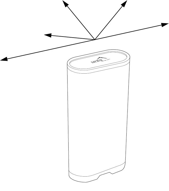
Placing and Positioning the Antenna
The RS4000 antenna should be mounted to the wall using the 3" mounting arm within
3' of the RS4000 when using the supplied 3-foot cables or 6' when using the optional
6-foot cables.
Figure 15: RS4000 180o Directional Antenna
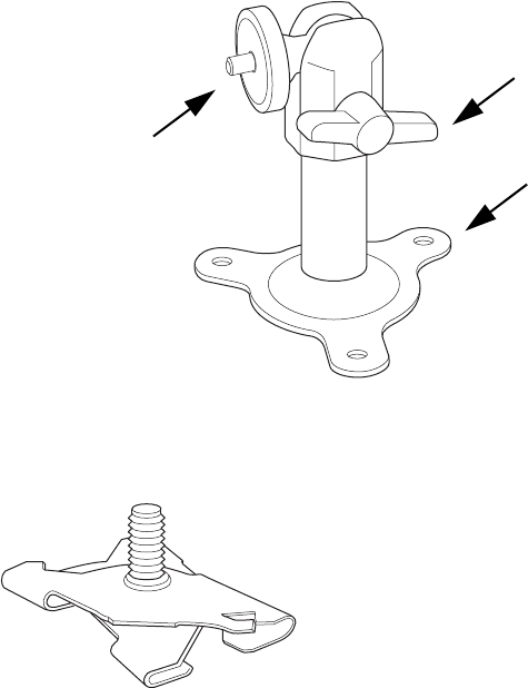
The antenna mount arm includes two screw-in base types to accommodate either
wall mounts (Figure 16) or ceiling tile rail mounts (Figure 17).
00179
ANT1
ANT2
Direction of Signal Coverage
24 Meru Access Point and Radio Switch Installation Guide © 2007 Meru Networks, Inc.
Installing the RS4000
Figure 16: Antenna Mounting Arm with Wall Bracket (shown attached)
Figure 17: Antenna Ceiling Tile Rail Base
The RS4000 antenna uses two RF cables (3-foot cables are supplied) to connect to the
SMA connectors on the top panel of the RS4000 (see Figure 8). The RF cables should
be attached to the RS4000 as a result of the procedures described in one of the
previous installation procedures.
Mount the antenna and connect the cables as described in the following:
1. Choose whether to hang the arm on a wall (including solid ceiling wall) or ceiling
tile rail.
—For wall or ceiling mount:
a. Using the screwholes in the mounting bracket as a template, mark and drill holes
into the wall.
b. Attach the bracket securely with three 1/4" diameter fasteners or one 5/16"
diameter and one 1/4" diameter fastener, if mounting to a wall stud (fasteners
are not supplied).
—For ceiling tile rail mount:
a. Pull apart the rail clamps so the ears can fit over the width of the ceiling rail.
b. Squeeze the rail clamp to attach to the ceiling rail.
00180
Wall bracket base
Angle adjusting lever
Antenna attachment
stud (threaded)
00183

Installing the RS4000
© 2007 Meru Networks, Inc. Installing the RS4000 25
c. Attach the rail mount base to the antenna arm by screwing the base into the
arm pole (you may have to unscrew and remove the wall mount base if it is
attached to the arm).
2. Connect the RF antenna wires from the RS4000 to the SMA connectors on the top
of the antenna, using Figure 8 or Figure 15 for orientation.
3. Attach the top of the antenna to the 1/4-20 threaded stud on the swivel head and
tighten against the antenna.
4. For a 180o directional antenna, position the antenna such that the logo on the top
of the antenna is pointing in the direction where reception is required.
5. Loosen the angle adjusting lever on the swivel assembly, if necessary, to adjust
the hanging angle.
6. Position the antenna to maximize the reception and tighten the adjusting lever.
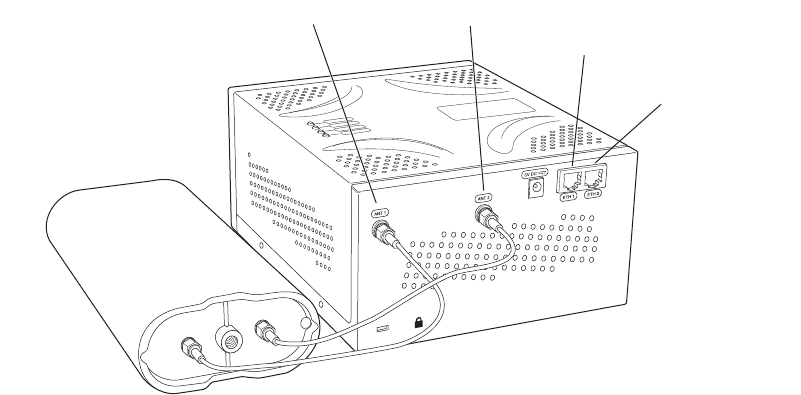
Hoffman/NEMA Enclosure RS4000 Installation
Use the procedures in this section to mount the RS4000 within the Hoffman or NEMA
enclosure. It will be necessary to modify the NEMA enclosure by drilling cable pass-
through holes before installing the RS4000.
Creating Cable Pass-through Holes in the NEMA Enclosure
To create cable pass-through holes in the NEMA enclosure, Meru supplies a template
with markings that coincide with the placement of the Ethernet and antenna cable
locations on the RS4000. Depending on the orientation of the RS4000 installation in
the NEMA enclosure, the template is to be used on the side of the enclosure adjacent
to the RS4000 top panel, where the cables connect.
1. Open the lid of the empty NEMA enclosure to provide unimpeded access to the
enclosure sides.
2. On the outside of the empty NEMA enclosure, locate the top center of the side
where the cables will exit.
3. Using the pattern on the supplied template, mark the center of the holes and drill
a 1/2" to 1" hole at each of the three locations specified by the template.
Note:
The recommended Meru installation is a vertical wall mount, which allows for
unimpeded air flow through the unit. The option to install the RS4000 within a
Hoffman/NEMA enclosure is left to the customer’s discretion, based on site-specific
factors such as protection and accessibility, etc. Installation in the Hoffman
enclosure requires drilling air vents and cable pass-through holes.
26 Meru Access Point and Radio Switch Installation Guide © 2007 Meru Networks, Inc.
Installing the RS4000
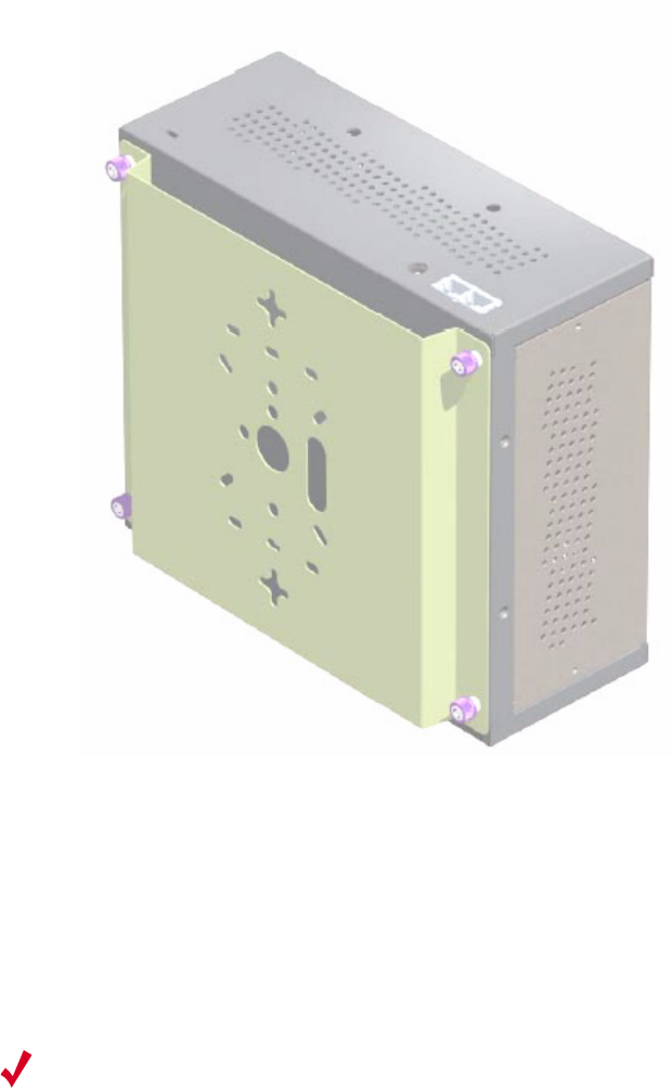
Mounting the RS4000 in the Hoffman/NEMA Enclosure
To mount the RS4000 in the Hoffman/NEMA enclosure, it is necessary to use the
optional mounting plate that is not supplied with the RS4000 packing items. This
procedure assumes the Hoffman/NEMA enclosure is already mounted at the site.
1. Remove the wall bracket from back of the RS4000, if attached, by unscrewing
each of the 4 knurled thumbscrews.
2. Attach the Hoffman/NEMA mounting plate to the back of the RS4000.
3. Attach the right-angle elbow joint to the antenna cable, if not already attached.
4. Attach the two antenna cables to the SMA antenna connectors labeled ANT1 and
ANT2 on the top panel of the RS4000 (see Figure 8) by turning the cable ends
clockwise until tight.
5. Attach two Ethernet cables to the Ethernet ports labeled ETH1 and ETH2 on the
top panel of the RS4000.
6. Place the RS4000 into the Hoffman/NEMA enclosure, and align the plate
screwholes with the holes in the Hoffman/NEMA enclosure.
7. Pass the Ethernet and antenna cables out of the Hoffman/NEMA enclosure through
the cable pass-through holes.
8. Tighten the captive screws on the mounting plate to the Hoffman/NEMA
enclosure.
9. Attach the antenna cables to the antenna (see Figure 15).
10. Position and align the bottom of the antenna over the threaded stud on the
antenna mount arm and tighten the threaded stud to the antenna.
Figure 18: RS4000 and Antenna Installed in NEMA Enclosure
Caution!
This method of mounting has not been evaluated by Underwriters
Laboratories.
00188
RS4000AntennaNEMA box

Where to Go From Here
© 2007 Meru Networks, Inc. Installing the RS4000 27
11. Connect the two Ethernet cables to the PoE device.
12. Apply power to the PoE component and network switch to power up the RS4000.
13. Test the reception for the antenna and then securely tighten the antenna.
14. Verify correct operating using the LEDs, as shown in “Checking LED Activity.”
15. Close the lid to the Hoffman/NEMA enclosure.
Where to Go From Here
Now that the RS4000 is installed, go to the Meru System Director Getting Started
Guide for instructions on initializing the controller and connecting the controller and
RS4000 to the Ethernet switch to form the WLAN. Return to this chapter to check the
status of the LEDs once the WLAN is operational.
28 Meru Access Point and Radio Switch Installation Guide © 2007 Meru Networks, Inc.
Checking LED Activity
Checking LED Activity
Radio switch status LEDs are provided on the face of the RS4000.
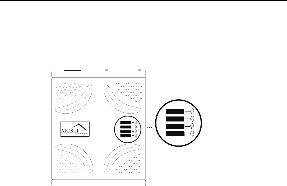
RS4000 Status LEDs
Status LEDs on the face of the RS4000 light, as shown in Figure 19.
. .
Figure 19: RS4000 Status LEDs
The RS4000 uses 4 LEDs. The functions of the status LEDs are described in Ta bl e 3 .
POWER
RADIO I
RADIO II
ETHERNET
POWER
RADIO I
RADIO II
ETHERNET
00185
Status LEDs

Checking LED Activity
© 2007 Meru Networks, Inc. Installing the RS4000 29
Table 3: RS4000 LED Descriptions
LED Function
Power
The Power status LED status is as follows:
zoff—power is off
zsolid red—when power is applied, system initializes for 40 sec-
onds and then the LED turns amber; after discovering the con-
troller the LED turns green. Otherwise, the system is in an
abnormal state (notify Customer Support).
zsolid amber—at any time, if this LED state persists longer than 40
seconds, notify Customer Support
zsolid green—system is fully operational
Radio I The Radio I LED is lit when radio packets are being transmitted and
when the radio is beaconing.
Radio II The Radio II LED is lit when radio packets are being transmitted and
when the radio is beaconing.
Ethernet
The Ethernet LED status is as follows:
zoff—no link
zsolid green—100Mbps connection
zblinking green—transmit or receive activity at 100Mbps
zsolid amber—10Mbps connection
zblinking amber—transmit or receive activity at 10Mbps
30 Meru Access Point and Radio Switch Installation Guide © 2007 Meru Networks, Inc.
Checking LED Activity

© 2007 Meru Networks, Inc. Installing the AP200 31
Chapter 3
Installing the AP200
This chapter describes how to physically install the AP200. It contains the following
sections:
zSafety Precautions
zUnpacking the AP200
zInstallation Requirements
zInstalling the Access Points
zWhere to Go From Here
zChecking LED Activity
Safety Precautions
IMPORTANT—Read and follow the instructions in “Regulatory Information” on page 63
before installing and operating this product.
Unpacking the AP200
As you unpack the AP200, confirm that the AP200 shipping package contains the items
listed on your packing list.
Shipments of the AP200 include a mounting bracket and mounting hardware for stan-
dard wall mounting. Optional mounting kits are available for mounting the AP200
above or below a hanging ceiling. The AP200 mounting studs are placed so they can
be used with brackets supplied by other vendors or to replace an AP100.
Note:
The AP200 has a security cable slot so you can secure the AP200 with a
standard security cable, such as those used to secure laptop computers.
32 Meru Access Point and Radio Switch Installation Guide © 2007 Meru Networks, Inc.
Installation Requirements
An array of holes on the mounting bracket (see Figure 20) allows it to be mounted on
the wall and over junction boxes or molly bolts. There are also holes for passing the
PoE Ethernet or external power supply cable through the bracket if the bracket is
mounted on a junction box or over the ceiling T-bar box hanger.
Figure 20: AP200 Mounting Bracket
Installation Requirements
The following recommended mounting locations provide the best reception for the
AP200:
zOn a horizontal surface, such as a table or a desk
zOn a vertical surface, usually a wall
zBelow a hanging ceiling
zAbove a hanging ceiling tiles (this installation is supported only for the AP200 with
the plastic enclosure removed)
Access point mount
Ceiling mount hole
Ceiling mount hole
A
ccess point mount
Access point mount
Locking detent
W
all cable access
S
uspended ceiling
c
able access
00100
Warning!
With plastic covers removed, this product is suitable for use in
environmental air space in accordance with the Section 300-22(c) of the National
Electric Code and Sections 2- 128.12 - 010 (3) and 12 - 100 of the Canadian Electrical
Code. Part 1. C22. 1. For other countries, consult local authorities for regulations.

Installation Requirements
© 2007 Meru Networks, Inc. Installing the AP200 33
To complete this installation, you need the items listed in Tab le 4 .
Table 4: AP200 Installation Items
Installation Type Consumable Items Required
Horizontal mounting None
Vertical mounting over a wall
stud
zTwo #6 x 2" wood screws for a wood stud; or
zTwo #6 x 1½" metal screws for a metal stud
zMounting bracket
Vertical mounting on sheetrock
zTwo #6 x 1" screws
zTwo #4-6 x 7/8" ribbed plastic wall anchors
zMounting bracket
Horizontal mounting below a
hanging ceiling
zTwo caddy fasteners
zTwo plastic spacers
zTwo keps nuts (with attached lock washer)
zMounting bracket
Mounting above a ceiling tile
(AP200 metal enclosure only)
zTwo T-ra i l cl i p s
zOne T-box hanger
zOne bracket mounting clip
zMounting bracket

34 Meru Access Point and Radio Switch Installation Guide © 2007 Meru Networks, Inc.
Installing the Access Points
You need the tools listed in Tab le 5 .
Table 5: AP200 Installation Tools
Installing the Access Points
Selecting a Location
The AP200 requires a location that meets the following:
zRelatively unobstructed access to the stations the AP serves
zPower over Ethernet (PoE) connection to the network switch servicing the
controller.
APs can obtain their power from 802.3af standard Power over Ethernet (PoE)-compat-
ible network switch or PoE power injector installed between the switch and the
AP200.
Select a location with minimal physical obstructions between the AP and the wireless
stations. In an office with cubicles, mounting the APs below a hanging ceiling or the
wall near the ceiling provides the least obstructed communications path. For an
external power supply connection, ensure the power source is near to where the
AP200 will be mounted.
Installation Type Tools Required
Horizontal mounting None
Vertical mounting over a wall stud
zDrill
z1/8"drill bit
zScrewdriver
Vertical mounting on sheetrock
zDrill
z3/16" drill bit
zScrewdriver
Horizontal mounting below a hanging ceiling zScrewdriver
zWrench or pliers
Mounting above a hanging ceiling (AP200
metal enclosure only)
zWrench or pliers
zScrewdriver

Installing the Access Points
© 2007 Meru Networks, Inc. Installing the AP200 35
Most installations receive the best coverage using the following guidelines:
Install APs toward the center of the building.
zDo not install APs near metal objects, such as heating ducts, metal doors, or
electric service panels.
zRelative to the ground, orient the antenna up or down, not sideways.
The AP200 is only intended for installation in Environment A as defined in IEEE
802.3af. All interconnected equipment must be contained within the same building,
including the interconnected equipment's associated LAN connection.
Attaching the AP200 Antennas
The AP200 is provided with external antenna ports. Make sure that all external
antennas and their associated wiring are located entirely indoors. The external
antennas are not suitable for outside use.
If the AP200 does not have external antennas, attach the antennas to the connectors
on the AP200 (see Figure 21). Rotate the knurled ring at the base of the antenna
clockwise to attach the antenna. The ring should be finger-tight.
Mounting the Access Point
You can mount an AP200 in the following ways:
zHorizontally, as described in the “Horizontal Mounting” section.
zVertically, as described in the “Vertical Mounting” section.
zBelow a hanging ceiling, as described in the “Mounting Below a Suspended
Ceiling” section.
zAbove a tiled hanging ceiling, as described in the “Mounting Above a Suspended
Ceiling” section.
Note:
The previous guidelines are general guidelines. Each site has its own unique
environment. Place access points accordingly.
Caution!
When changing the orientation of the antennas, be sure to slightly loosen
the knurled ring before moving the antenna. Retighten the ring afterward.
Otherwise, you might damage the internal cabling in the AP.
36 Meru Access Point and Radio Switch Installation Guide © 2007 Meru Networks, Inc.
Installing the Access Points
Horizontal Mounting
To horizontally mount an AP200:
1. Place the AP200 flat on the horizontal surface.
2. For each antenna, loosen the knurled ring at the base of the antenna (see
Figure 21), point the antenna straight up, then retighten the ring.
Figure 21: AP200 Antenna Connection
3. Connect one end of the PoE 100BaseT Ethernet cable to the 100/1000 Ethernet
connector, shown in Figure 22.
Figure 22: AP200 Connector Panel
Turn clockwise
to tighten
A
ntenna
ETHERNET
3.3 VDC ANT 2
00110
Caution!
Be sure to connect the Ethernet cable to the Ethernet port; the cable can
mistakenly be plugged into the Console port.
CONSOLE
ANT 1 ANT 2
3.3 VDC
ETHERNET
00108
100/1000
Ethernet
(Reserved)
Console
port
Antenna 1 Antenna 2
Power
inlet
Reset
(Push to restore
default settings)
(Currently
unsupported)
Installing the Access Points
© 2007 Meru Networks, Inc. Installing the AP200 37
Vertical Mounting
To vertically mount an AP:
1. Using the bracket holes as a template, mark the location on the wall for the two
AP bracket mounting screws. They are placed 4 ½ inches apart, center-to-center,
one above the other. If you are not using plastic wall anchors, you must center
the mounting screws on a wall stud. If you do not center the mounting screws on
a wall stud, you must use plastic wall anchors.
Figure 23: AP200 Bracket
2. Drill holes at the locations you marked:
—3/16-inch holes if you are using plastic anchors
—1/8-inch holes if you are using only the screws
3. If you are using plastic anchors, install them in the holes.
4. Screw in the screws most of the way, so that the screw head is about 1/16 of an
inch from the wall.
5. Mount the bracket on the screws, placing the circular portion of the keyhole
mounts over the screw heads and sliding the bracket down.
6. Tighten the screws to secure the bracket.
7. Align the AP200 mounting posts over the circular portion of the keyhole mounts,
push the AP in and slide the AP down until it engages with the locking detents.
You should hear it snap in place.
Access point mount
Ceiling mount hole
Ceiling mount hole
A
ccess point mount
Access point mount
Locking detent
W
all cable access
S
uspended ceiling
c
able access
00100
38 Meru Access Point and Radio Switch Installation Guide © 2007 Meru Networks, Inc.
Installing the Access Points
Figure 24: Aligning the AP200 with the Bracket
Figure 25: Sliding the AP200 into the Bracket
8. For external antennas, loosen the knurled ring at the base of each antenna (see
Figure 21), point the antenna straight up, then retighten the ring.
00115
Mounting bracket attached to wall
AP200
00112
Mounting bracket
Installing the Access Points
© 2007 Meru Networks, Inc. Installing the AP200 39
9. Connect one end of the PoE 100BaseT Ethernet cable to the 100/1000 Ethernet
connector, shown in Figure 22.
Mounting Below a Suspended Ceiling
The optional suspended ceiling mounting kit allows the AP200 mounting bracket to
attach to suspended ceiling T-rails (see Figure 26).
Note:
To comply with NEC code, attach a grounding wire to any of the screws used
to attach the AP200 to the mounting bracket.
Figure 26: Mounting the AP200 to a Suspended Ceiling Rail
To mount an AP200 below a suspended ceiling:
1. Determine the location on the ceiling rail where the AP will be mounted and
remove the ceiling tiles.
2. Place each of the two caddy fasteners on the ceiling T-rail and twist to attach to
the rail.
3. Adjust the distance between the caddy fasteners by using the mounting bracket
holes as a guide.
4. Tighten the caddy fasteners in place using a standard screwdriver. Do not
overtighten.
Caution!
Be sure to connect the Ethernet cable to the Ethernet port; the cable can
mistakenly be plugged into the Console port.
Suspended ceiling T-rail
Mounting bracke
t
Keps nuts with attached
locking washer
Caddy fastener(
s)
Plastic spacer(s
)
00102

40 Meru Access Point and Radio Switch Installation Guide © 2007 Meru Networks, Inc.
Installing the Access Points
5. Place each spacer on the caddy fastener stud. The spacer legs should contact the
ceiling
T-rail.
6. Align the mounting bracket keyholes with the caddy fastener studs and slide the
AP200 to the narrow end of the hole.
7. Attach a keps nut to each caddy fastener stud and hand tighten. Do not
overtighten.
8. Align the AP200 mounting posts over the circular portion of the keyhole mounts,
push the AP in and slide the AP down until it engages with the locking detents
(see Figure 25). You should hear it snap in place.
9. For each antenna, loosen the knurled ring at the base of the antenna (see
Figure 21), point the antenna straight down, then retighten the ring.
10. Connect one end of the PoE 100BaseT Ethernet cable to the 100/1000 Ethernet
connector, shown in (see Figure 22).
Mounting Above a Suspended Ceiling
The optional T-bar box hanger mounting kit allows the AP200 to be mounted above
suspended ceiling T-rails (see Figure 27). The installation attaches the T-bar box
hanger to the ceiling rails using clips. The AP200 attaches to the mounting bracket
that is attached to the T-bar box hanger.
The AP200 antennas should point straight down for this type of installation. You may
need to modify thicker tiles to support this installation.
Caution!
Be sure to connect the Ethernet cable to the Ethernet port; the cable can
mistakenly be plugged into the Console port.
Warning!
When installed in air-handling spaces, such as above a suspended ceiling,
the AP200 is to be powered via PoE only (PoE is required).
Warning!
The AP200 with the metal enclosure exposed meets the requirements for
fire resistance and low smoke-generating characteristics required by Section 300-
22(C) of the National Electrical Code (NEC) for installation in a building’s
environmental air space. You must remove the plastic enclosure to reveal the
plenum-rated AP200 metal case for installations above a suspended ceiling.
Additionally, you must use Ethernet cable that meets the requirements for operating
in plenums and environmental air space (in accordance with Section 300-22(C) of the
NEC).
Installing the Access Points
© 2007 Meru Networks, Inc. Installing the AP200 41
Figure 27: Mounting the AP200 Above a Suspended Ceiling
To mount an AP200 above suspended ceiling rails:
1. Determine the location on the ceiling rails where the AP will be mounted and
remove the ceiling tile.
2. Unpack the T-bar hanger kit and unfold the legs of the T-bar hanger.
3. Locate the bracket mounting clip holes on the mounting bracket (see Figure 28).
One hole attaches the bracket perpendicular to the box hanger; the other mounts
the bracket parallel to the box hanger.
Figure 28: Box Hanger Mounting Bracket Holes
Warning!
Any Fast Ethernet (FE) cables installed in air-handling spaces should be
suitable under NEC Article 800.50 and marked accordingly for use in plenums and air-
handling spaces with regard to smoke propagation, such as CL2-P, CL3-P, MPP (Multi
Purpose Plenum), or CMP (Communications Plenum).
Bracket mounting clip
Mounting bracket
T-bar hanger Height adjustment scre
w
Height adjustment screw
Suspended ceiling T-rail
T-rail clips
Antennas
Access Point 200
00103
Mounting bracket holes
00101
42 Meru Access Point and Radio Switch Installation Guide © 2007 Meru Networks, Inc.
Installing the Access Points
4. Attach the U-joint of the clip to the T-bar and snap in place (see Figure 29).
.
Figure 29: Attaching the Mounting Bracket to the Box Hanger
5. Pass the long end clip through the large center hole to the underside of the the
mounting bracket clip and then attach the bracket to the clip using the supplied
screw (see Figure 29 for orientation).
6. Hold the AP200 next to the mounting bracket to estimate the height of the T-bar
box hanger to provide enough clearance for the external antennas, which should
be pointing down.
7. Adjust the height of the box hanger using the height adjusting screws (see
Figure 26).
8. Clip the box hanger T-rail clips to the ceiling rails, making sure they are securely
attached.
9. Connect a drop wire to a building structural element and through the hole
provided in the bracket mounting clip. The U.S. National Electrical Safety Code
requires this additional support.
10. Connect the posts of the AP200 to the three keyholes of the mounting bracket and
slide into the keyhole (see Figure 25), ensuring the locking detent is engaged. You
will hear a click.
11. For each antenna, loosen the knurled ring at the base of the antenna (see
Figure 21), point the antenna down, then retighten the ring.
12. Connect one end of the PoE 100BaseT Ethernet cable to the 100/1000 Ethernet
connector, shown in Figure 22.
00104
Caution!
Be sure to connect the Ethernet cable to the Ethernet port; the cable can
mistakenly be plugged into the Console port.
Where to Go From Here
© 2007 Meru Networks, Inc. Installing the AP200 43
13. Check that the AP200 is operating correctly before replacing the ceiling tile to
the ceiling. Verify correct operating using the LEDs, as shown in Checking LED
Activity.
Where to Go From Here
Now that the AP200 is installed, go to the Meru System Director Getting Started
Guide for instructions on initializing the controller and connecting the controller and
APs to the Ethernet switch to form the WLAN. Return to this chapter to check the
status of the LEDs once the WLAN is operational.
Checking LED Activity
Access point status LEDs are provided on the Ethernet connector and on the face of
the AP200.
Ethernet Connector LEDs
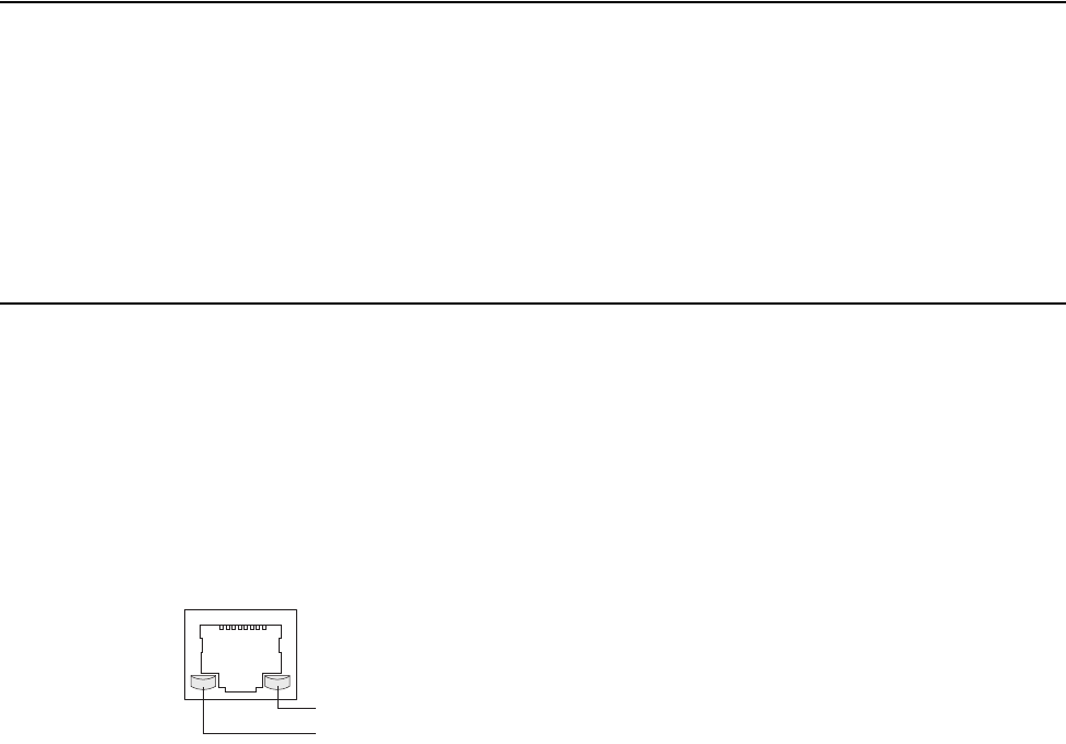
After the AP200 is connected, the LEDs near the RJ-45 connector should light, as
shown in Figure 30.
Figure 30: RJ-45 LEDs
The green LED on the left blinks if any Ethernet activity is taking place. If there is
no Ethernet activity, the LED is off. The LED on the right is solid green if an Ethernet
link is present. If no Ethernet link is present or connectivity is lost, the LED is off.
Ethernet activity
Link present
00129
44 Meru Access Point and Radio Switch Installation Guide © 2007 Meru Networks, Inc.
Checking LED Activity
AP200 Status LEDs
Four status LEDs on the face of the AP200 also light, as shown in Figure 31.
. .
Figure 31: AP200 Status LEDs
The functions of the status LEDs are described in Tab le 7.
When the AP200 is first connected to the controller and any time the access point is
rebooted thereafter, the AP initializes with and then is programmed by the
controller. When the AP is first powered up, all LEDs are green. Thereafter, the
Status LED (see Figure 31) color reflects the various operating states (Tabl e 7).
AP200
RF2
RF1
STATUS
POWER
00113

Checking LED Activity
© 2007 Meru Networks, Inc. Installing the AP200 45
Table 6: AP200 LED Descriptions
Table 7: AP200 Controller Status Information
LED Function
RF 2
The status LED for Radio 2 is a follows:
off—no radio present
yellow—radio initializing
red—radio failure
solid green—radio OK
blinking green—radio activity
RF 1
The status LED for Radio 1 is a follows:
off—no radio present
yellow—radio initializing
red—radio failure
solid green—radio OK
blinking green—radio activity
Status AP-Controller operational status (see Tabl e 7)
Power green—presence of power
State Interpretation AP200 LED Cycle
Attempting to dis-
cover Controller
In the process of discovering the con-
troller. The AP is connected but not
associated with the controller. If the
AP does not associate with the control-
ler after a period of time, verify that
the connection between the AP and the
switch or the switch and the controller
is unbroken.
Green/Red/Blue/R
ed
Connected Normal operation without security.
Blue/Blue/Blue/R
ed
Blue/Blue/Blue/R
ed, for 2 seconds.
Authenticated Normal operation with security. Blue blinka

46 Meru Access Point and Radio Switch Installation Guide © 2007 Meru Networks, Inc.
Checking LED Activity
Disconnected
Access point was once connected to a
controller and configured by the con-
troller, but can no longer find that con-
troller
Green/Purple/
Green/Purple
Standalone Access point is operating in a standal-
one mode Purple blink
Downloading Downloading image or configuration
from the controller
Green/Blue
Green/Blue
Error State Access point is in an error state.
Call Meru technical support
Red (blinking or
solid)
a. The AP200 LEDs cycle from bright to dim for each “blink.”
State Interpretation AP200 LED Cycle

© 2007 Meru Networks, Inc. Installing the AP150 47
Chapter 4
Installing the AP150
This chapter describes how to physically install the AP150. It contains the following
sections:
zSafety Precautions
zUnpacking the AP150
zInstallation Requirements
zInstalling the Access Points
zWhere to Go From Here
zChecking LED Activity
Safety Precautions
IMPORTANT—Read and follow the instructions in Appendix B, “Regulatory Informa-
tion” on page 63 before installing and operating this product.
This product is intended to be supplied by a UL Listed power supply, marked Class 2
or LPS, and rated minimum 5 Vdc, 3A.
Unpacking the AP150
Confirm that the AP150 shipping package contains the AP150 access point with
attached mounting bracket
Caution!
The AP150 is not certified for plenum installations, and should not be
installed in the plenum space.
48 Meru Access Point and Radio Switch Installation Guide © 2007 Meru Networks, Inc.
Installation Requirements
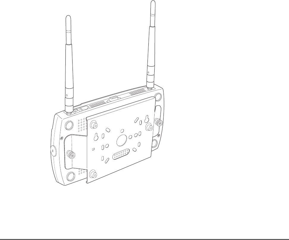
Figure 32: AP150 with Mounting Bracket
Installation Requirements
If you choose not to use the AP150 mounting bracket, the backside of the AP150
contains two keyholes to accommodate a simple wall mount.
A mounting bracket can be used for many wall mounting configurations. The AP150
bracket mounting studs are placed so they can be used with brackets supplied by
other vendors or to replace an AP100. An array of holes on the mounting bracket (see
Figure 32) allow it to be mounted on the wall and over junction boxes or molly bolts.
There are also holes for passing the PoE Ethernet or external power supply cable
through the bracket if the bracket is mounted on a junction box.
Additional optional mounting kits are available for mounting the AP150below a
hanging ceiling, using the mounting bracket.
00177

Installation Requirements
© 2007 Meru Networks, Inc. Installing the AP150 49
Note:
The AP150 has two security cable slots (one on each side of the AP150) so you
can secure the AP150 with a standard security cable, such as those used to secure
laptop computers.
The following recommended mounting locations provide the best reception for the
AP150:
zOn a horizontal surface, such as a table or a desk
zOn a vertical surface, usually a wall
zBelow a hanging ceiling
To complete this installation, you need the items listed in Tab le 8 .
Table 8: AP150 Installation Items
Caution!
The AP150 is not certified for plenum installations, and should not be
installed in the plenum space.
Installation Type Consumable Items Required
Horizontal mounting None
Vertical mounting over a wall
stud
zTwo #6 x 2" wood screws for a wood stud; or
zTwo #6 x 1½" metal screws for a metal stud
zMounting bracket
Vertical mounting on sheetrock
zTwo #6 x 1" screws
zTwo #4-6 x 7/8" ribbed plastic wall anchors
zMounting bracket
Horizontal mounting below a
hanging ceiling
zTwo caddy fasteners
zTwo plastic spacers
zTwo keps nuts (with attached lock washer)
zMounting bracket

50 Meru Access Point and Radio Switch Installation Guide © 2007 Meru Networks, Inc.
Installing the Access Points
You need the tools listed in Tab le 9 .
Table 9: AP150 Installation Tools
Installing the Access Points
Selecting a Location
The AP150 requires a location that meets the following:
zRelatively unobstructed access to the stations the AP serves
zPower over Ethernet (PoE) connection to the network switch servicing the
controller.
APs can obtain their power from 802.3af standard Power over Ethernet (PoE)-compat-
ible network switch or PoE power injector installed between the switch and the
AP150.
Select a location with minimal physical obstructions between the AP and the wireless
stations. In an office with cubicles, mounting the APs below a hanging ceiling or the
wall near the ceiling provides the least obstructed communications path.
Installation Type Tools Required
Horizontal mounting None
Vertical mounting over a wall
stud
zDrill
z1/8"drill bit
zScrewdriver
z1/8"Allen wrench
Vertical mounting on sheetrock
zDrill
z3/16" drill bit
zScrewdriver
z1/8"Allen wrench
Horizontal mounting below a
hanging ceiling
zScrewdriver
zWrench or pliers
z1/8"Allen wrench

Installing the Access Points
© 2007 Meru Networks, Inc. Installing the AP150 51
Most installations receive the best coverage using the following guidelines:
Install APs toward the center of the building.
zDo not install APs near metal objects, such as heating ducts, metal doors, or
electric service panels.
zRelative to the ground, orient the antenna up or down, not sideways.
The AP150 is only intended for installation in Environment A as defined in IEEE
802.3af. All interconnected equipment must be contained within the same building,
including the interconnected equipment's associated LAN connection.
Attaching the AP150 Antennas
The AP150 is provided with external antenna ports. Make sure that all external
antennas and their associated wiring are located entirely indoors. The external
antennas are not suitable for outside use.
If the AP150 does not have external antennas, attach the antennas to the connectors
on the AP150 (see Figure 33). Rotate the knurled ring at the base of the antenna
clockwise to attach the antenna. The ring should be finger-tight.
Mounting the Access Point
You can mount an AP150 in the following ways:
zHorizontally, as described in the “Horizontal Mounting” section.
zVertically, as described in the “Vertical Mounting with the Mounting Bracket”
section.
zBelow a hanging ceiling, as described in the “Mounting Below a Suspended
Ceiling” section.
Horizontal Mounting
To horizontally mount an AP150:
1. Place the AP150 flat on the horizontal surface.
2. For each antenna, loosen the knurled ring at the base of the antenna (see
Figure 33), point the antenna straight up, then retighten the ring.
Note:
The previous guidelines are general guidelines. Each site has its own unique
environment. Place access points accordingly.
Caution!
When changing the orientation of the antennas, be sure to slightly loosen
the knurled ring before moving the antenna. Retighten the ring afterward.
Otherwise, you might damage the internal cabling in the AP.
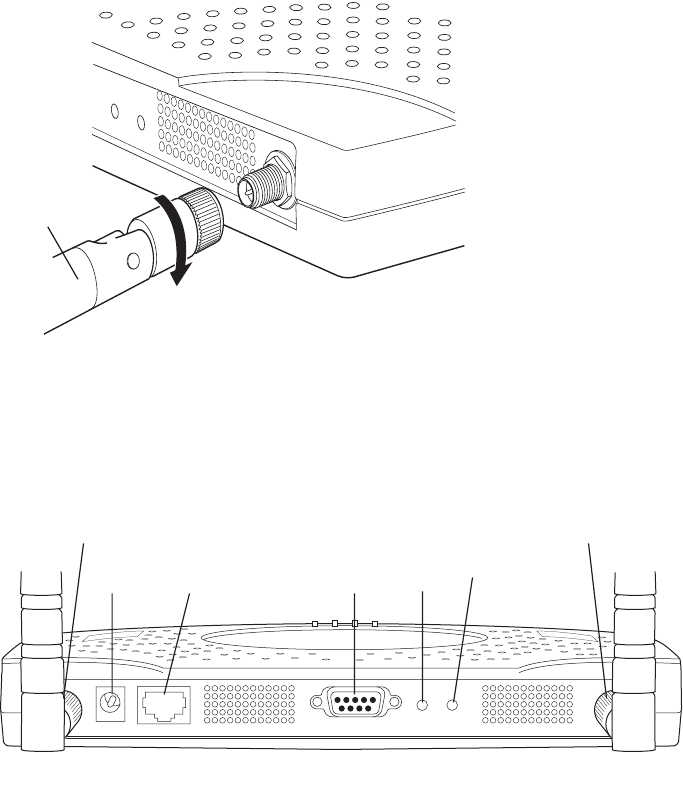
52 Meru Access Point and Radio Switch Installation Guide © 2007 Meru Networks, Inc.
Installing the Access Points
Figure 33: AP150 Antenna Connection
3. Connect one end of the PoE 100BaseT Ethernet cable to the 100/1000 Ethernet
connector, shown in Figure 34.
Figure 34: AP150 Connector Panel
Vertical Mounting the AP150
To perform a simple wall mount using the keyholes on the back of the AP150:
1. Remove the attached mounting bracket from the back of the AP150.
2. Mark the location on the wall for two mounting screws. They are placed 4.3"
apart, center-to-center, or one above the other. If you are not using plastic wall
anchors, you must either center the mounting screws on a wall stud or use plastic
wall anchors.
3. Drill holes at the locations you marked:
—3/16-inch holes if you are using plastic anchors
—1/8-inch holes if you are using only the screws
00172
ANT 2
RELOAD
RESET
Turn clockwise
to tighten
A
ntenna
ANT1 ANT2
LAN
DC 5V CONSOLE RESET RELOAD
00173
Power Ethernet
connection
Console
port Reset
button Reload
Antenna 1 Antenna 2
(reserved) (reserved)
Installing the Access Points
© 2007 Meru Networks, Inc. Installing the AP150 53
4. If you are using plastic anchors, install them in the holes.
5. Screw in the screws most of the way, so that the screw head is about 1/16 of an
inch from the wall.
6. Align the AP150 keyholes over the mounting screws and slightly pull down (or
across, if mounting sideways).
7. For external antennas, loosen the knurled ring at the base of each antenna (see
Figure 33), point the antenna straight up, then retighten the ring.
8. Connect one end of the PoE 100BaseT Ethernet cable to the 100/1000 Ethernet
connector, shown in Figure 34.
Vertical Mounting with the Mounting Bracket
The AP150 uses thumbscrews to attach to the mounting bracket or mounting plate
that allows the access point to be mounted on a vertical surface. Additionally, three
shoulder screws may be installed on the mounting bracket to allow the AP150 and
attached bracket to mount over a previously installed Cisco 1200 mounting bracket.
To vertically mount an AP:
1. If not mounting the AP150 to a previously third-party installed mounting bracket,
use a 1/8" Allen wrench to remove the shoulder screws from the mounting
bracket, if already attached.
2. Using the bracket holes as a template, remove the bracket from the AP150 (or use
the stencil in Appendix D, “Mounting Bracket Stencils”) to mark the location on
the wall for the two AP bracket mounting screws. They are placed 4.3 inches
apart, center-to-center. If you are not using plastic wall anchors, you must center
the mounting screws on a wall stud. If you do not center the mounting screws on
a wall stud, you must use plastic wall anchors.
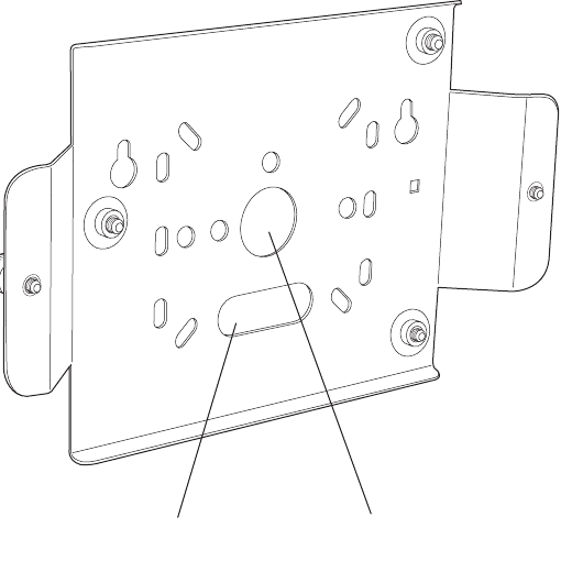
54 Meru Access Point and Radio Switch Installation Guide © 2007 Meru Networks, Inc.
Installing the Access Points
Figure 35: AP150 Bracket
3. Drill holes at the locations you marked:
—3/16-inch holes if you are using plastic anchors
—1/8-inch holes if you are using only the screws
4. If you are using plastic anchors, install them in the holes.
5. Screw in the screws most of the way, so that the screw head is about 1/16 of an
inch from the wall.
6. Mount the bracket on the screws, placing the circular portion of the keyhole
mounts over the screw heads and sliding the bracket down.
7. Tighten the screws to secure the bracket.
8. Align the AP150 with the bracket thumbscrews (see Figure 36) and tighten the
thumbscrews to attach the bracket.
00167
Suspended ceiling
cable access Wall cable access
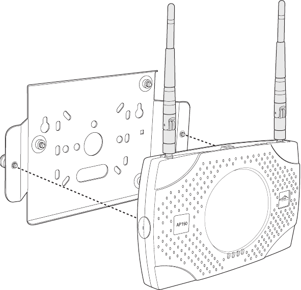
Installing the Access Points
© 2007 Meru Networks, Inc. Installing the AP150 55
Figure 36: Aligning the AP150 with the Bracket
9. For external antennas, loosen the knurled ring at the base of each antenna (see
Figure 33), point the antenna straight up, then retighten the ring.
10. Connect one end of the PoE 100BaseT Ethernet cable to the 100/1000 Ethernet
connector, shown in Figure 34.
00169
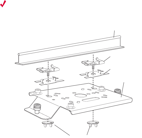
56 Meru Access Point and Radio Switch Installation Guide © 2007 Meru Networks, Inc.
Installing the Access Points
Mounting Below a Suspended Ceiling
The optional suspended ceiling mounting kit allows the AP150 mounting bracket to
attach to suspended ceiling T-rails (see Figure 37).
Note:
To comply with NEC code, attach a grounding wire to any of the screws used
to attach the AP150 to the mounting bracket.
Figure 37: Mounting the AP150 to a Suspended Ceiling Rail
To mount an AP150 below a suspended ceiling:
1. Using a 1/8" Allen wrench, remove the shoulder screws from the mounting
bracket, if already attached.
2. Determine the location on the ceiling rail where the AP will be mounted and
remove the ceiling tiles.
3. Place each of the two caddy fasteners on the ceiling T-rail and twist to attach to
the rail.
4. Adjust the distance between the caddy fasteners by using the mounting bracket
holes as a guide.
5. Tighten the caddy fasteners in place using a standard screwdriver. Do not
overtighten.
6. Place each spacer on the caddy fastener stud. The spacer legs should contact the
ceiling T-rail.
7. Align the mounting bracket keyholes with the caddy fastener studs and slide the
AP150 to the narrow end of the hole.
00170
Washers
Suspended ceiling T-rail
Mounting bracke
t
Caddy fastener(
s)
Spacer(s)

Where to Go From Here
© 2007 Meru Networks, Inc. Installing the AP150 57
8. Attach a keps nut to each caddy fastener stud and hand tighten. Do not
overtighten.
9. Align the AP150 with the bracket thumbscrews (see Figure 36) and tighten the
thumbscrews to attach the bracket.
10. For each antenna, loosen the knurled ring at the base of the antenna (see
Figure 33), point the antenna straight down, then retighten the ring.
11. Connect one end of the PoE 100BaseT Ethernet cable to the 100/1000 Ethernet
connector, shown in (see Figure 34).
Where to Go From Here
Now that the AP150 is installed, go to the Meru System Director Getting Started
Guide for instructions on initializing the controller and connecting the controller and
APs to the Ethernet switch to form the WLAN. Return to this chapter to check the
status of the LEDs once the WLAN is operational.
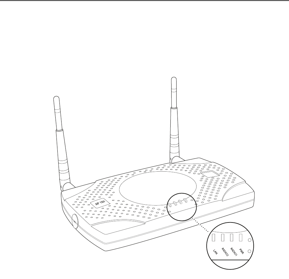
58 Meru Access Point and Radio Switch Installation Guide © 2007 Meru Networks, Inc.
Checking LED Activity
Checking LED Activity
Access point status LEDs are provided on the Ethernet connector and on the face of
the AP150.
AP150 Status LEDs
Four status LEDs on the face of the AP150 also light, as shown in Figure 38.
.
Figure 38: AP150 Status LEDs
When the AP150 is first connected to the controller and any time the access point is
rebooted thereafter, the AP initializes with and then is programmed by the
controller. The Status LED (see Figure 38) color reflects the various operating states
(Tab le 1 0).
PWR
LAN
RADIO2
RADIO1
Status LEDs
00166

Checking LED Activity
© 2007 Meru Networks, Inc. Installing the AP150 59
Table 10: AP150 LED Descriptions
LED Function
Power
The Power status LED status is as follows:
zoff—power is off
zsolid red—when power is applied, system initializes for 40 sec-
onds and then the LED turns amber; after discovering the con-
troller the LED turns green. Otherwise, the system is in an
abnormal state (notify Customer Support).
zsolid amber—at any time, if this LED state persists longer than 40
seconds, notify Customer Support
zsolid green—system is fully operational
Radio I The Radio I LED is lit when radio packets are being transmitted and
when the radio is beaconing.
Radio II The Radio II LED is lit when radio packets are being transmitted and
when the radio is beaconing.
Ethernet
The Ethernet LED status is as follows:
zoff—no link
zsolid green—100Mbps connection
zblinking green—transmit or receive activity at 100Mbps
zsolid amber—10Mbps connection
zblinking amber—transmit or receive activity at 10Mbps
60 Meru Access Point and Radio Switch Installation Guide © 2007 Meru Networks, Inc.
Checking LED Activity

© 2007 Meru Networks, Inc. Specifications 61
Appendix A
Specifications
This chapter provides specifications for Meru Access Points and contains the following
sections:
zWireless Interface
zEthernet Interface
zPhysical
Wireless Interface
Table 11: Wireless Interface Specifications
Feature Details
Wireless Standards z802.11a, 802.11b, 802.11g, 802.11n
Antennas zTwo to six external antennas. Omnidirectional and direc-
tional antennas for specific coverage requirements
Wireless Medium
Access
zWi-Fi Compliant 802.11 MAC standard
Power Management zPower-save mode for clients in both QoS mode and non-
QoS mode
Frame Size
zPeak frame size of > 2346 bytes
zFragmentation and reassembly of 802.11/Ethernet
frames
Client Activities Sup-
ported
zActive scanning and passive scanning
zPre-authentication
zPower-save mode supported
62 Meru Access Point and Radio Switch Installation Guide © 2007 Meru Networks, Inc.
Ethernet Interface
Ethernet Interface
Physical
Physical specifications for Meru Access Points are provided in the access point Data
Sheet. Contact your Meru sales engineer for a copy of the document.
Feature Detail
Wireline Standard
zOne Ethernet (IEEE 802.3) interface, supporting
half-duplex and full-duplex modes
zSupports the Power over Ethernet (PoE) IEEE
802.3af standard

© 2007 Meru Networks, Inc. Regulatory Information 63
Appendix B
Regulatory Information
The Meru Access Points (APs) must be installed and used in strict accordance with the
manufacturer’s instructions as described in the user documentation that comes with
the product. For country-specific approvals, see below. Meru Networks, Inc. is not
responsible for any radio or television interference caused by unauthorized modifi-
cation of APs, or the substitution or attachment of connecting cables and equipment
other than that specified by Meru Networks, Inc. The correction of interference
caused by such unauthorized modification, substitution or attachment is the respon-
sibility of the user. Meru Networks, Inc. and its authorized resellers or distributors
are not liable for any damage or violation of government regulations that may arise
from the user failing to comply with these guidelines.
USA
Underwriters Laboratories
For the AP150 series, the AP200 series, and the RS4000, the following statement and
notices are applicable:
Use only with Listed I.T.E. equipment.
Notices
The unit is intended for installation in Environment A as defined in IEEE 802.3.af. All
interconnected equipment must be contained within the same building, including the
interconnected equipment's associated LAN connection.
Suitable for use in environmental air space in accordance with Section 300-22(c) of
the National Electrical Code, and Sections 2-128, 12-010(3) and 12-100 of the Cana-
dian Electrical Code, Part 1, C22.1.

64 Meru Access Point and Radio Switch Installation Guide © 2007 Meru Networks, Inc.
USA
FCC Radiation Exposure Statement
Radio Frequency Interference Requirements
Interference Statement
These devices comply with Part 15 of the FCC Rules. Operation of the devices is
subject to the following two conditions: (1) The devices may not cause harmful inter-
ference, and (2) The devices must accept any interference that may cause undesired
operation.
This equipment has been tested and found to comply with the limits for a Class B
digital device, pursuant to Part 15 of the FCC Rules. These limits are designed to
provide reasonable protection against harmful interference in a residential installa-
tion. This equipment generates, uses, and can radiate radio frequency energy. If the
equipment is not installed and used in accordance with the instructions, the equip-
ment may cause harmful interference to radio communications. There is no guar-
antee, however, that such interference will not occur in a particular installation. If
this equipment does cause harmful interference to radio or television reception
(which can be determined by turning the equipment off and on), the user is encour-
aged to try to correct the interference by taking one or more of the following
measures:
zRelocate this device.
zIncrease the separation between the device and the receiver.
zConnect the device into an outlet on a circuit different from that of other
electronics.
zConsult the dealer or an experienced radio technician for help.
Caution!
The radiated output power of the Meru Networks devices is well below the
FCC radio frequency exposure limits. However, the Meru Access Points
should be used in such a manner that the potential for human contact dur-
ing normal operation is minimized. When installing and operating these
devices, keep a minimum distance of 20 cm (8 inches) between the anten-
nas and any persons/users in the vicinity.
Note:
Meru Access Point
These devices are restricted to indoor use because they operate in the
5.15 to 5.25 GHz frequency range. The FCC requires such products to be
used indoors for the frequency range 5.15 GHz to 5.25 GHz to reduce the
potential for harmful interference to co-channel Mobile Satellite systems.

Canada. Industry Canada (IC)
© 2007 Meru Networks, Inc. Regulatory Information 65
This device must not be co-located or operating in conjunction with any other
antenna or transmitter.
For products available in the USA and Canadian markets, only channels 1 through 11
can be operated. Selection of other channels is not authorized.
Canada. Industry Canada (IC)
The Class B digital portion of this apparatus complies with Canadian standard ICES-
003.
These devices comply with RSS210, Issue 5 of Industry Canada.
For products available in the USA and Canadian markets, only channels 1 through 11
can be operated. Selection of other channels is not authorized.
Operation is subject to the following two conditions: (1) this device may not cause
interference, and (2) this device must accept any interference, including interfer-
ence that may cause undesired operation of this device.
This device and its listed antenna(s) must not be co-located or operated in conjunc-
tion with any other antenna or transmitter
L’utilisation de ce dispositif est autorisée seulement aux conditions suivantes: (1) il
ne doit pas produire de brouillage et (2) l’utilisateur du dispositif doit étre prêt à
accepter tout brouillage radioélectrique reçu, même si ce brouillage est susceptible
de compromettre le fonctionnement du dispositif.
The term "IC" before the equipment certification number only signifies that the
Industry Canada technical specifications were met.
To reduce the potential radio interference to other users, the antenna type and gain
should be chosen so that the equivalent isotropically radiated power (EIRP) is not
more than that required for successful communication.
To prevent radio interference to the licensed service, this device is intended to be
operated indoors and away from windows to provide maximum shielding. Equipment
(or its transmit antenna) that is installed outdoors is subject to licensing.
Note:
The Meru Access Point must be installed and used in strict accordance
with the manufacturer’s instructions as described in the user documenta-
tion that comes with the product. Any other installation or use may violate
FCC Part 15 regulations. Modifications not expressly approved by Meru
Networks, Inc. could void your authority to operate the equipment.

66 Meru Access Point and Radio Switch Installation Guide © 2007 Meru Networks, Inc.
Canada. Industry Canada (IC)
Pour empecher que cet appareil cause du brouillage au service faisant l’objet d’une
licence, il doit etre utilze a l’interieur et devrait etre place lin des fenetres afin de
Fournier un ecram de blindage maximal. Si le matriel (ou son antenne d’emission) est
installe a l’exterieur, il doit faire l’objet d’une licence.
Access Points have been designed to operate with the antennas listed below.
Antennas not included in this list are strictly prohibited for use with these devices.
The required antenna impedance is 50 ohms.
Caution!
Exposure to Radio Frequency Radiation.
The installer of this radio equipment must ensure that the antenna is
located or pointed such that it does not emit an RF field in excess of
Health Canada limits for the general population; consult Safety Code 6,
obtainable from Health Canada’s website http://www.hc-sc.gc.ca/rpb.
This equipment complies with IC RSS-102 radiation exposure limits set
forth for an uncontrolled environment. This equipment should be installed
and operated with a minimum distance of 20cm between the antennas and
any persons/users in the vicinity.
Note:
Meru Access Points
These devices are restricted to indoor use because they operate in the
5.15 to 5.25 GHz frequency range. Industry Canada requires such products
to be used indoors for the frequency range 5.15 GHz to 5.25 GHz to reduce
the potential for harmful interference to co-channel Mobile Satellite sys-
tems.
AP Model Antenna Type Gain (2.4 GHz) Gain (5 GHz)
AP200 Dual-Band Omni-Directional
SAA04-220050 2 dBi 3 dBi
AP200 Dual-Band Omni-Directional
TWX-614XRSXX 4 dBi 5 dBi
AP150 Dual-Band Omni-Directional
MMO224580608 6 dBi 8 dBi
Europe—EU Declaration of Conformity and Restrictions
© 2007 Meru Networks, Inc. Regulatory Information 67
To reduce potential radio interference to other users, the antenna type and its gain
should be chosen so that the equivalent isotropically radiated power (e.i.r.p.) is not
more than that permitted for successful communication.
Europe—EU Declaration of Conformity and
Restrictions
EN 300 328. Electromagnetic Compatibility and Radio Spectrum Matters (ERM).
Wideband transmission systems, data transmission equipment operating in the 2.4
GHz ISM (Industrial, Scientific, and Medical frequency bands in the range of 902–928
MHz, 2.4–2.485 GHz, and
5.15–5.25 GHz) band and using spread spectrum modulation techniques, harmonized
EN standards covering essential requirements under article 3.2 of the R&TTE direc-
tive.
AP150 Single-Band Omni-Directional
SAA04-050280 8 dBi
AP150 Panel
MP24013 XFPTNF
13 dBi
AP150 Dual-Band Omni-Directional
SAA04-220050
2 dBi 3 dBi
RS4000 Dual-Band Multi-Channel Omni-
Directional
MN-ACC-ANTRSO
4 dBi 4.5 dBi
RS4000 Dual-Band Multi-Channel 180o
MN-ACC-ANTRSOH 5 dBi 5.5 dBi
This equipment is marked with either the CE Mark, the alert symbol, and the notified
body's number and can be used throughout the European Community. This mark indi-
cates compliance with the R&TTE Directive 1999/5/EC and the relevant parts of the
following technical specifications.

68 Meru Access Point and Radio Switch Installation Guide © 2007 Meru Networks, Inc.
Europe—EU Declaration of Conformity and Restrictions
EN 301 893. Broadband Radio Access Networks (BRAN). 5 GHz high-performance
RLAN, harmonized EN standards covering essential requirements of article 3.2 of the
R&TTE directive.
EN 301 489-17. Electromagnetic Compatibility and Radio Spectrum Matters (ERM).
Electromagnetic Compatibility (EMC) Standard for Radio Equipment and Services,
Part 17 Specific Conditions for Wideband Data and HIPERLAN Equipment.
EN 60950-1. Safety of Information Technology Equipment.
Meru Networks, Inc. declares that their Access Points comply with the essential
requirements and other relevant provisions of Directive 1999/5/EC.
Meru Networks, Inc. vakuuttaa täten että Access Points tyyppinen laite on direktiivin
1999/5/EY oleellisten vaatimusten ja sitä koskevien direktiivin muiden ehtojen
mukainen.
Hierbij verklaart Meru Networks, Inc. dat het toestel Access Points in overeenstem-
ming is met de essentiële eisen en de andere relevante bepalingen van richtlijn
1999/5/EG.
Bij deze verklaart Meru Networks, Inc. dat deze Access Points voldoet aan de essen-
tiële eisen en aan de overige relevante bepalingen van Richtlijn 1999/5/EC.
Par la présente, Meru Networks, Inc. déclare que l’appareil Access Points est
conforme aux exigences essentielles et aux autres dispositions pertinentes de la
directive 1999/5/CE.
Par la présente, Meru Networks, Inc. déclare que ce Access Points est conforme aux
exigences essentielles et aux autres dispositions de la directive 1999/5/CE qui lui
sont applicables.
Härmed intygar Meru Networks, Inc. att denna Access Points står I överensstämmelse
med de väsentliga egenskapskrav och övriga relevanta bestämmelser som framgår av
direktiv 1999/5/EG.
Undertegnede Meru Networks, Inc. erklærer herved, at følgende udstyr Access Points
overholder de væsentlige krav og øvrige relevante krav i direktiv 1999/5/EF.
Hiermit erklärt Meru Networks, Inc. dass sich dieser/diese/dieses Access Points in
Übereinstimmung mit den grundlegenden Anforderungen und den anderen relevanten
Vorschriften der Richtlinie 1999/5/EG befindet.
Hiermit erklärt Meru Networks, Inc. die Übereinstimmung des Gerätes Access Points
mit den grundlegenden Anforderungen und den anderen relevanten Festlegungen der
Richtlinie 1999/5/EG.
Marking by the alert symbol indicates that usage restrictions apply.

Europe—EU Declaration of Conformity and Restrictions
© 2007 Meru Networks, Inc. Regulatory Information 69
Con la presente Meru Networks, Inc. dichiara che questo Access Points è conforme ai
requisiti essenziali ed alle altre disposizioni pertinenti stabilite dalla direttiva
1999/5/CE.
Por medio de la presente Meru Networks, Inc. declara que el Access Points cumple
con los requisitos esenciales y cualesquiera otras disposiciones aplicables o exigibles
de la Directiva 1999/5/CE.
Meru Networks, Inc. declara que este Access Points está conforme com os requisitos
essenciais e outras disposições da Directiva 1999/5/CE.
Hawnhekk, Meru Networks, Inc. jiddikjara li dan Access Points jikkonforma mal-
htigijiet essenzjali u ma provvedimenti ohrajn relevanti li hemm fid-Dirrettiva
1999/5/EC.
Käesolevaga kinnitab Meru Networks, Inc. seadme Access Points vastavust direktiivi
1999/5/EÜ põhinõuetele ja nimetatud direktiivist tulenevatele teistele asjako-
hastele sätetele.
Alulírott, Meru Networks, Inc. nyilatkozom, hogy a Access Points megfelel a vonat-
kozó alapvetõ követelményeknek és az 1999/5/EC irányelv egyéb elõírásainak.
Meru Networks, Inc. týmto vyhlasuje, e Access Points splna základné poiadavky a
všetky príslušné ustanovenia Smernice 1999/5/ES.
Meru Networks, Inc. tímto prohlašuje, e tento Access Points je ve shode se základními
poadavky a dalšími príslušnými ustanoveními smernice 1999/5/ES.
Šiuo Meru Networks, Inc. deklaruoja, kad šis Access Points atitinka esminius reikala-
vimus ir kitas 1999/5/EB Direktyvos nuostatas.
Ar šo Meru Networks, Inc. deklare, ka Access Points atbilst Direktivas 1999/5/EK
butiskajam prasibam un citiem ar to saistitajiem noteikumiem.
Niniejszym, Meru Networks, Inc., deklaruje, ze Access Points spelnia wymagania
zasadnicze oraz stosowne postanowienia zawarte Dyrektywie 1999/5/EC.
These products are intended to be used in all countries of the European Economic
Area with the following restrictions:
IEEE 802.11a Restrictions
zThese products are for indoor use only (5150–5250 MHz).
zTo ensure compliance with local regulations, be sure to set your Access Point to
the country in which you are using the Access Point.
ΠΑΡΟΨΣΑ Meru Networks Inc. ∆ΗΛΩΝΕΙ ΟΤΙ Access Points
Ρ
ΦΩΝΕΤΑΙ ΠΡΟΣ ΤΙΣ ΟΥΣΙΩ∆ΕΙΣ ΑΠΑΙΤΗΣΙΣ ΚΑΙ ΤΙΣ ΛΟΙΠΕΣ ΣΧΕΤΙΚΕ
Σ
Ε
ΙΣ ΤΗΣ Ο∆ΗΓΙΑΣ 1999/5/ΕΚ.

70 Meru Access Point and Radio Switch Installation Guide © 2007 Meru Networks, Inc.
Japan
zThe Meru Networks, Inc. products can be used only indoors in the following
countries: Austria, Belgium, Bulgaria, Czech Republic, Germany, Cyprus,
Denmark, Estonia, Finland, France, Greece, Hungary, Iceland, Ireland, Italy,
Latvia, Lithuania, Luxembourg, Malta, The Netherlands, Norway, Portugal,
Poland, Romania, Spain, Slovak Republic, Slovenia, Sweden, Switzerland, Turkey,
and United Kingdom.
EEE 802.11b/g Restrictions
zFrance—In all Metropolitan départements, wireless LAN frequencies can be used
under the following conditions, either for public or private use:
Indoor use: maximum power (EIRP) of 100 mW for the entire 2400–2483.5 MHz
frequency band.
Japan
Model 208
Model 208 Rev 2 Module
Model AP208 Rev 2
Model 201
Model AP201 Rev 2
003NY06089 0000 003GZ06018 0000 003WY06035 0000
003NY07014 0000 003GZ07002 0000 003WY07004 0000
003NY07015 0000 003GZ07003 0000 003WY07005 0000
003NY06117 0000 003GZ06026 0000 003WY06043 0000
003NY07015 0000 003GZ07003 0000 003WY07005 0000

Manufacturing Information
© 2007 Meru Networks, Inc. Regulatory Information 71
Model AP150
Manufacturing Information
The AP150 and AP200 are built in Taiwan. Factory information is provided under NDA
and upon request.
003NY06122 0000 003GZ06030 0000 003WY06046 0000
72 Meru Access Point and Radio Switch Installation Guide © 2007 Meru Networks, Inc.
Manufacturing Information

© 2007 Meru Networks, Inc. Channels 73
Appendix C
Channels
B-1
This appendix provides the access point radio channels supported by the world’s
regulatory domains.
This appendix contains the following section:
zChannels
Channels
IEEE 802.11a
The channel identifiers, channel center frequencies, and regulatory domains of each
IEEE 802.11a 20-MHz-wide channel are listed in Tab le 1 2.
Note:
All channel sets are restricted to indoor usage except the Americas, which
allow for indoor and outdoor use on channels 52 through 64 in the United
States.
Table 12: IEEE 802.11a Channels
Channel
Number
Frequency in
MHz
Regulatory Domains
Americas Japan
34 5170 - X
36 5180 X -

74 Meru Access Point and Radio Switch Installation Guide © 2007 Meru Networks, Inc.
Channels
38 5190 - X
40 5200 X -
42 5210 - X
44 5220 X -
46 5230 - X
48 5240 X -
52 5260 X -
56 5280 X -
60 5300 X -
64 5320 X -
149 5745 X -
153 5765 X -
157 5785 X -
161 5805 X -
165 5825 X -
Table 12: IEEE 802.11a Channels (Continued)
Channel
Number
Frequency in
MHz
Regulatory Domains
Americas Japan

Channels
© 2007 Meru Networks, Inc. Channels 75
IEEE 802.11b/g
The channel identifiers, channel center frequencies, and regulatory domains of each
IEEE 802.11b/g 22-MHz-wide channel are listed in Ta bl e 13 .
Note:
Mexico is included in the Americas regulatory domain; however, channels 1
through 8 are for indoor use only while channels 9 through 11 can be used
indoors and outdoors. Users are responsible for ensuring that the channel
set configuration complies with the regulatory standards of Mexico.
Table 13: IEEE 802.11b/g Channels
Channel
Number
Frequency
in MHz
Regulatory Domains
Americas EMEA Israel China Japan
1 2412 X X - X X
2 2417 X X - X X
3 2422 X X X X X
4 2427 X X X X X
5 2432 X X X X X
6 2437 X X X X X
7 2442 X X X X X
8 2447 X X X X X
9 2452 X X X X X
10 2457 X X - X X
11 2462 X X - X X

76 Meru Access Point and Radio Switch Installation Guide © 2007 Meru Networks, Inc.
Channels
12 2467 - X - - X
13 2472 - X - - X
14 2484 - - - -
X
(for 802.11b
only)
Table 13: IEEE 802.11b/g Channels (Continued)
Channel
Number
Frequency
in MHz
Regulatory Domains
Americas EMEA Israel China Japan

© 2007 Meru Networks, Inc. Mounting Bracket Stencils 77
Appendix D
Mounting Bracket Stencils
B-1
This appendix provides drawings of the AP mounting brackets.
AP150 Mounting Bracket Stencil
The following page contains the stencil of the AP150 mounting bracket. It should be
printed at 100% scale to ensure correct dimensions.
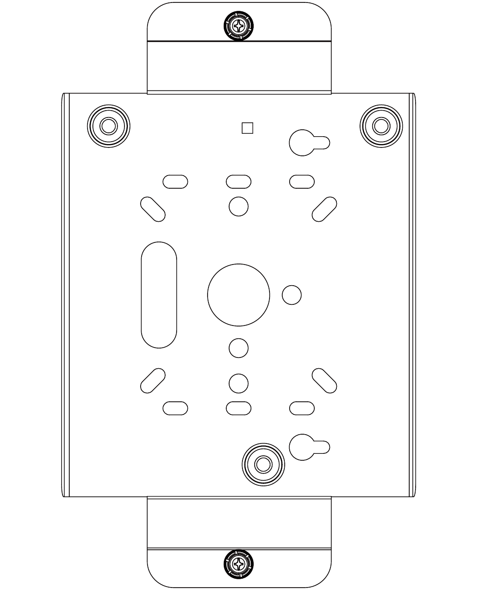
78 Meru Access Point and Radio Switch Installation Guide © 2007 Meru Networks, Inc.
AP150 Mounting Bracket Stencil

79
MERU NETWORKS, INC.
Limited Product Warranty
This Limited Product Warranty applies to the original end-user customer of the Meru product which you
purchased for your own use, and not for resale (“Product”), from Meru Networks, Inc. (“Meru”) or its
authorized reseller (“Reseller”).
Limited Warranties
—One-year limited hardware warranty: Meru warrants to you that Meru hardware (other than Third
Party Products as described below) will be free from defects in materials and workmanship for a
one-year period after the date of delivery of the applicable product to you from Meru or its
Reseller (the “Hardware Warranty Period”). If Meru receives written notice from you of such
defects during the Hardware Warranty Period, Meru will, at its option, either repair or replace
Meru hardware that Meru determines to be defective. Replacement products may be remanufac-
tured units, and will be warranted for the remainder of the original Hardware Warranty Period, or
if greater, for thirty days from delivery of such replacement. Should Meru be unable to repair or
replace the Meru hardware, Meru (or its Reseller, as applicable) will refund to you the purchase
price of the Product.
—90-Day Limited Software Warranty: Meru warrants to you that, for a 90-day period after the date
of delivery of the applicable product to you from Meru or its Reseller (the “Software Warranty
Period”), when properly installed and used, (a) the media on which the Meru software is provided
will be free from defects in materials or workmanship; and (b) the Meru software will substantially
conform to the functional specifications in the applicable documentation. If Meru receives written
notice from you of a breach of this warranty during the Software Warranty Period and is able to
reproduce the defect, Meru will, at its option, either repair or replace the defective Meru software.
Should Meru be unable to repair or replace the Meru software, Meru (or its Reseller, as applicable)
will refund to you the purchase price of the Product.
Exclusions
The warranty on the Product shall not apply to defects resulting from the following:
—Alteration or modification of the Product in any way, including without limitation configuration
with software or components other than those supplied by Meru or integration with parts other
than those supplied by Meru.
—Abuse, damage or otherwise being subjected to problems caused by negligence or misapplication
(including without limitation improper or inadequate maintenance or calibration), relocation of
the products (including without limitation damage caused by use of other than Meru shipping
containers), or use of the products other than as specified in the applicable Meru product docu-
mentation (including without limitation incompatible operating environments and systems), or
improper site preparation or maintenance.
—Damage as a result of accidents, extreme power surge, extreme electromagnetic field, acts of
nature or other causes beyond the control of Meru.
—Use of the Product with software, interfacing, parts or supplies not supplied by Meru.
The warranty on the Product does not apply if the Product is sold, or in the case of software, licensed,
for free for evaluation or demonstration purposes.
80 Meru Access Point and Radio Switch Installation Guide
Meru expressly disclaims any warranty or obligation to support the Product for all operating
environments – for example, as illustration and not limitation, Meru does not warrant or
ensure interoperability of the Product with future telecommunication systems or other future
software or hardware.
You understand and acknowledge that the Products may generate, use or radiate radio
frequency energy and may interfere with radio communications and/or radio and television
receptions if is not used and/or installed in accordance with the documentation for such
products. WHILE MERU USES COMMERCIALLY REASONABLE EFFORTS TO
ENSURE COMPLIANCE OF THE PRODUCTS WITH APPLICABLE UNITED STATES
FEDERAL COMMUNICATIONS COMMISSION AND PROTECT AGAINST HARMFUL
INTERFERENCES, YOU ACKNOWLEDGE AND AGREE THAT INTERFERENCES
WITH RADIO COMMUNICATIONS AND/OR RADIO AND TELEVISION
RECEPTIONS MAY OCCUR AND THAT MERU WILL NOT BE LIABLE FOR ANY
DAMAGES OR INCONVENIENCE BASED ON SUCH INTERFERENCES.
Third Party Products - The above Limited Warranties are exclusive of products
manufactured by third parties (“Third Party Products”). If such third party manufacturer
provides a separate warranty with respect to the Third Party Product, Meru will include such
warranty in the packaging of the Meru Product.
Return procedures
To obtain warranty service you must: (a) obtain a return materials authorization number
(“RMA#”) from Meru by contacting rmaadmin@merunetworks.com, and (b) deliver the
Product, in accordance with the instructions provided by Meru, along with proof of purchase
in the form of a copy of the bill of sale including the Product’s serial number, contact
information, RMA# and detailed description of the defect, in either its original package or
packaging providing the Product with a degree of protection equivalent to that of the original
packaging, to Meru at the address below. You agree to obtain adequate insurance to cover loss
or damage to the Product during shipment.
If you obtain an RMA# and return the defective Product as described above, Meru will pay
the cost of returning the Product to Meru. Otherwise, you agree to bear such cost, and prior
to receipt by Meru, you assume risk of any loss or damage to the Product. Meru is responsible
for the cost of return shipment to you if the Meru Product is defective.
Returned products which are found by Meru to be not defective, returned out-of-warranty or
otherwise ineligible for warranty service will be repaired or replaced at Meru’s standard
charges and shipped back to you at your expense.
At Meru’s sole option, Meru may perform repair service on the Product at your facility, and
you agree to provide Meru with all reasonable access to such facility and the Product, as
required by Meru. On-site repair service may be available and is governed by the specific
terms of your purchase.
All replaced parts, whether under warranty or not, are the property of Meru.
Warranty limitations
THE WARRANTIES SET FORTH ABOVE ARE EXCLUSIVE AND NO OTHER
WARRANTY, WHETHER WRITTEN OR ORAL, IS EXPRESSED OR IMPLIED BY
MERU, TO THE MAXIMUM EXTENT PERMITTED BY LAW. THERE ARE NO OTHER
81
WARRANTIES RESPECTING THE PRODUCT AND DOCUMENTATION AND
SERVICES PROVIDED UNDER THIS AGREEMENT, INCLUDING WITHOUT
LIMITATION ANY WARRANTY OF DESIGN, MERCHANTABILITY, FITNESS FOR A
PARTICULAR PURPOSE (EVEN IF MERU HAS BEEN INFORMED OF SUCH
PURPOSE), TITLE OR AGAINST INFRINGEMENT OF THIRD PARTY RIGHTS. IF
ANY IMPLIED WARRANTY CANNOT BE DISCLAIMED UNDER APPLICABLE LAW,
THEN SUCH IMPLIED WARRANTY SHALL BE LIMITED IN DURATION TO THE
HARDWARE AND SOFTWARE WARRANTY PERIODS DESCRIBED ABOVE.
NO AGENT OF MERU IS AUTHORIZED TO ALTER OR EXCEED THE WARRANTY
OBLIGATIONS OF MERU.
MERU SPECIFICALLY DOES NOT WARRANT THAT THE MERU SOFTWARE WILL
BE ERROR FREE OR OPERATE WITHOUT INTERRUPTION.
THE REMEDIES IN THIS LIMITED PRODUCT WARRANTY ARE YOUR SOLE AND
EXCLUSIVE REMEDIES, AND MERU’S SOLE AND EXCLUSIVE LIABILITY, FOR
BREACH OF THE HARDWARE OR SOFTWARE WARRANTY SET FORTH ABOVE.
Limitations of Liability
You acknowledge and agree that the consideration which you paid to Meru does not include
any consideration by Meru of the risk of consequential, indirect or incidental damages which
may arise in connection with your use of, or inability to use, the Product. THUS, MERU AND
ITS RESELLER WILL NOT BE LIABLE FOR ANY INDIRECT, INCIDENTAL,
SPECIAL, PUNITIVE OR CONSEQUENTIAL DAMAGES, INCLUDING WITHOUT
LIMITATION LOST PROFITS, LOST BUSINESS, LOST DATA, LOSS OF USE, OR
COST OF COVER INCURRED BY YOU ARISING OUT OF OR RELATED TO YOUR
PURCHASE OR USE OF, OR INABILITY TO USE, THIS PRODUCT OR THE
SERVICES, UNDER ANY THEORY OF LIABILITY, WHETHER IN AN ACTION IN
CONTRACT, STRICT LIABILITY, TORT (INCLUDING NEGLIGENCE) OR OTHER
LEGAL OR EQUITABLE THEORY, EVEN IF MERU OR ITS RESELLER KNEW OR
SHOULD HAVE KNOWN OF THE POSSIBILITY OF SUCH DAMAGES. IN ANY
EVENT, THE CUMULATIVE LIABILITY OF MERU OR ITS RESELLER FOR ALL
CLAIMS WHATSOEVER RELATED TO THE PRODUCT OR THE SERVICE WILL NOT
EXCEED THE PRICE YOU PAID FOR THE PRODUCT OR SERVICES GIVING RISE TO
SUCH CLAIMS.
THE LIMITATIONS SET FORTH HEREIN ARE INTENDED TO LIMIT THE LIABILITY
OF MERU AND ITS RESELLERS AND SHALL APPLY NOTWITHSTANDING ANY
FAILURE OF ESSENTIAL PURPOSE OF ANY LIMITED REMEDY.
The jurisdiction applicable to you may not allow the limitations of liability or damages set
forth above, in which case such limitation shall only apply to you to the extent permitted in
such jurisdiction.
Additional Information
This Limited Product Warranty shall be governed by and construed in accordance with the
laws of the State of California, U.S.A., exclusive of its conflict of laws principles. The U.N.
Convention on Contracts for the International Sale of Goods shall not apply.
82 Meru Access Point and Radio Switch Installation Guide
This Limited Product Warranty is the entire and exclusive agreement between you and Meru
with respect to its subject matter, and any modification or waiver of any provision of this
statement is not effective unless expressly set forth in writing by an authorized representative
of Meru.
All inquiries or claims made under this Limited Product Warranty must be sent to Meru at the
following address:
Meru Networks Inc.,
894 Ross Drive, CA 94087, USA
Tel: 408-215-5300
Fax: 408-215-5301
Email: support@merunetworks.com

Meru Networks, Inc.
894 Ross Drive
Sunnyvale, CA 94087
408-215-5300
www.merunetworks.com