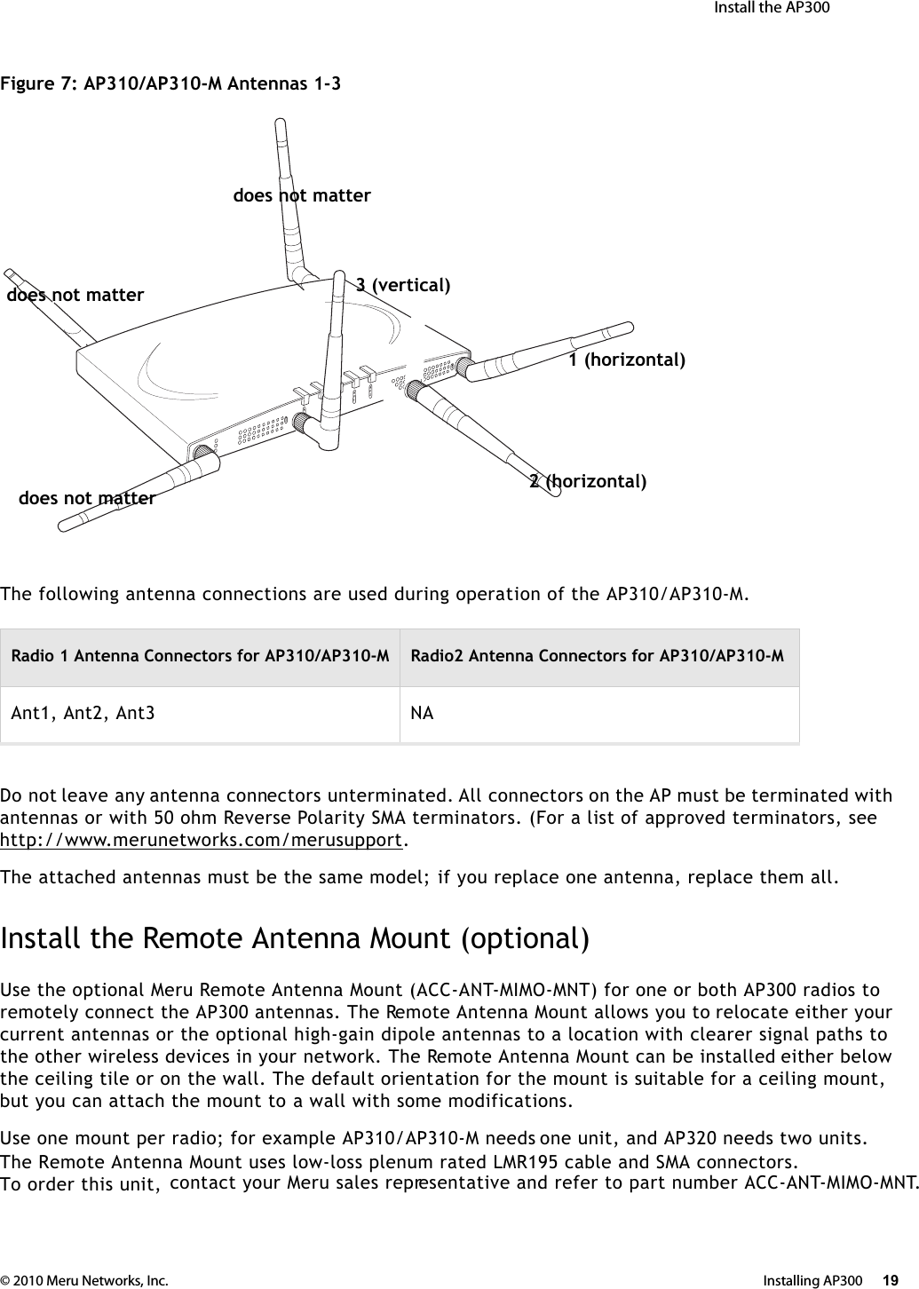
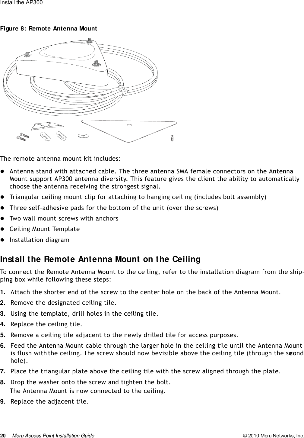
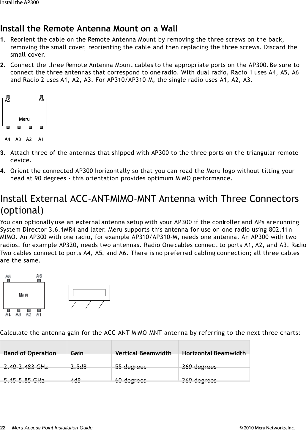
Meru Networks AP310M MULTI RADIO 802.11a/b/g/n WIRELESS LAN ACCESS POINT User Manual AP Install
Meru Networks Inc. MULTI RADIO 802.11a/b/g/n WIRELESS LAN ACCESS POINT AP Install
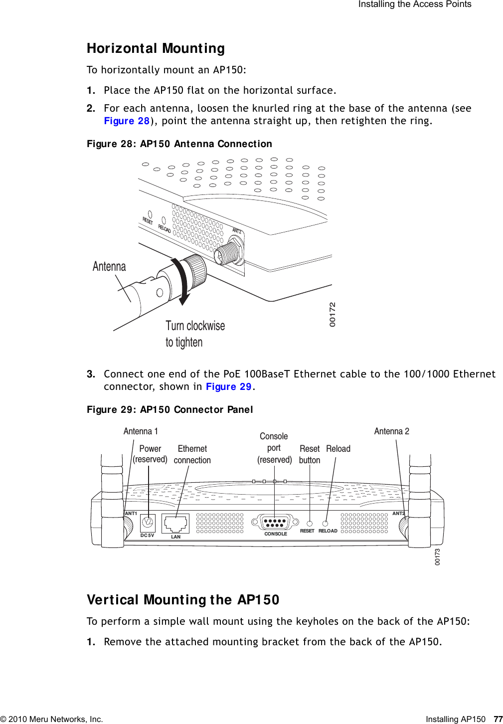
UserManual.wiki
>
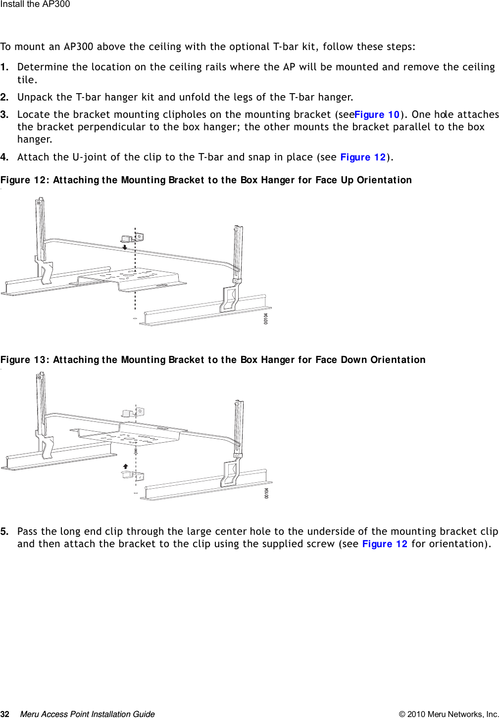
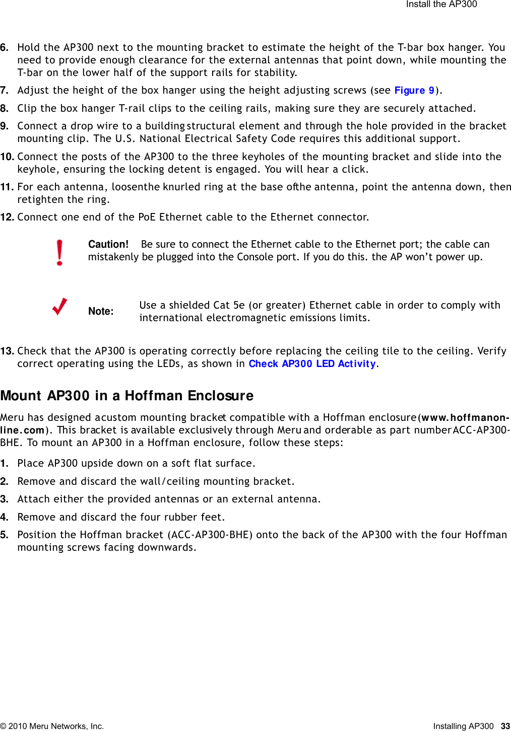
Meru Networks
>
AP310M User Manual
Users Manual
Navigation menu
Upload a User Manual
Namespaces
Wiki Guide
HTML
PDF
Info
Views
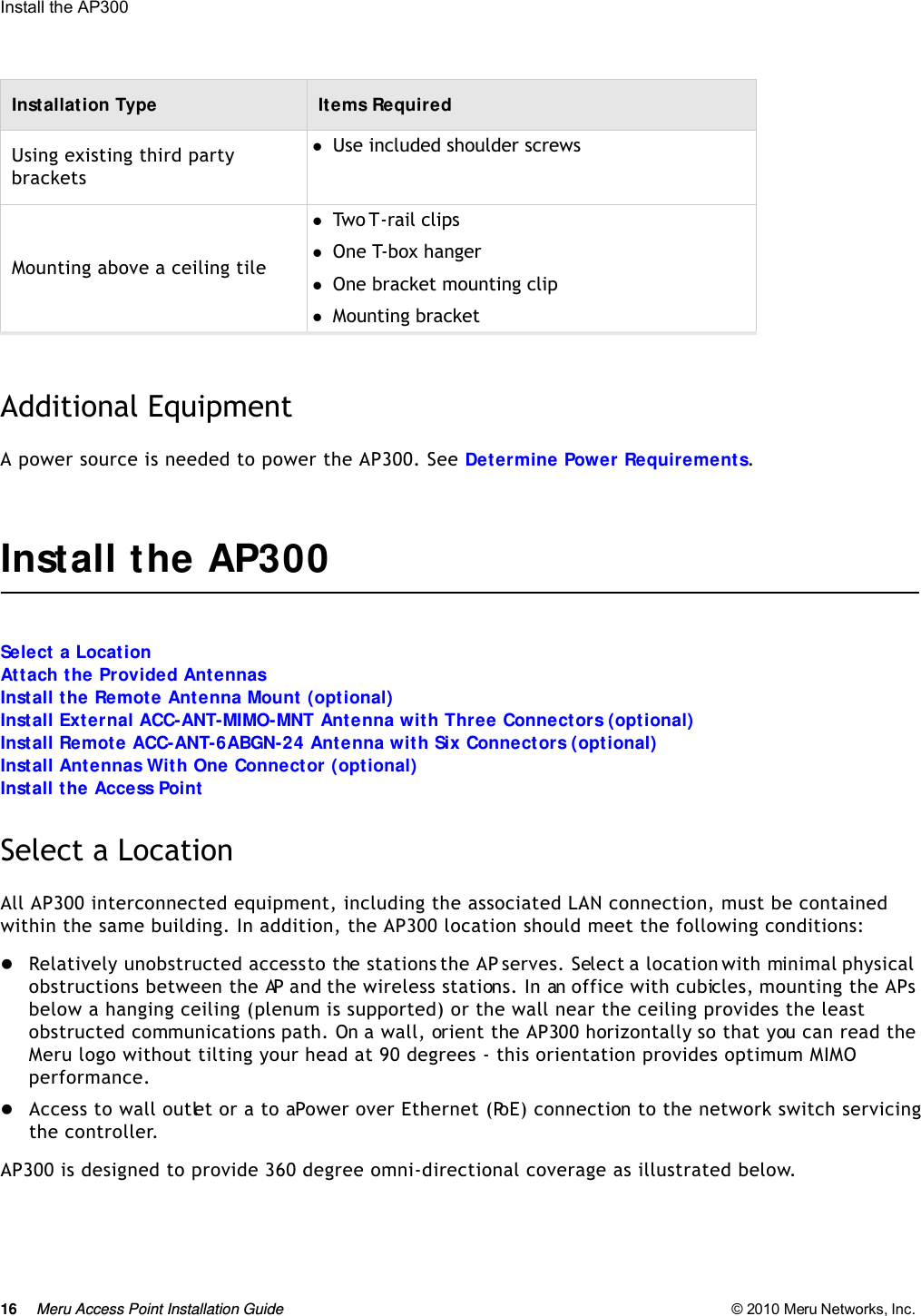
User Manual
Discussion / Help
Navigation