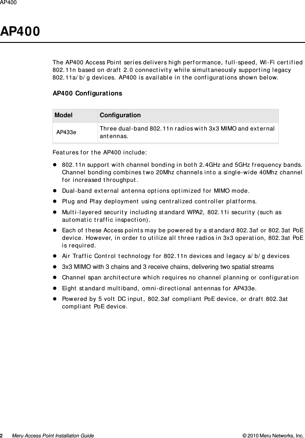
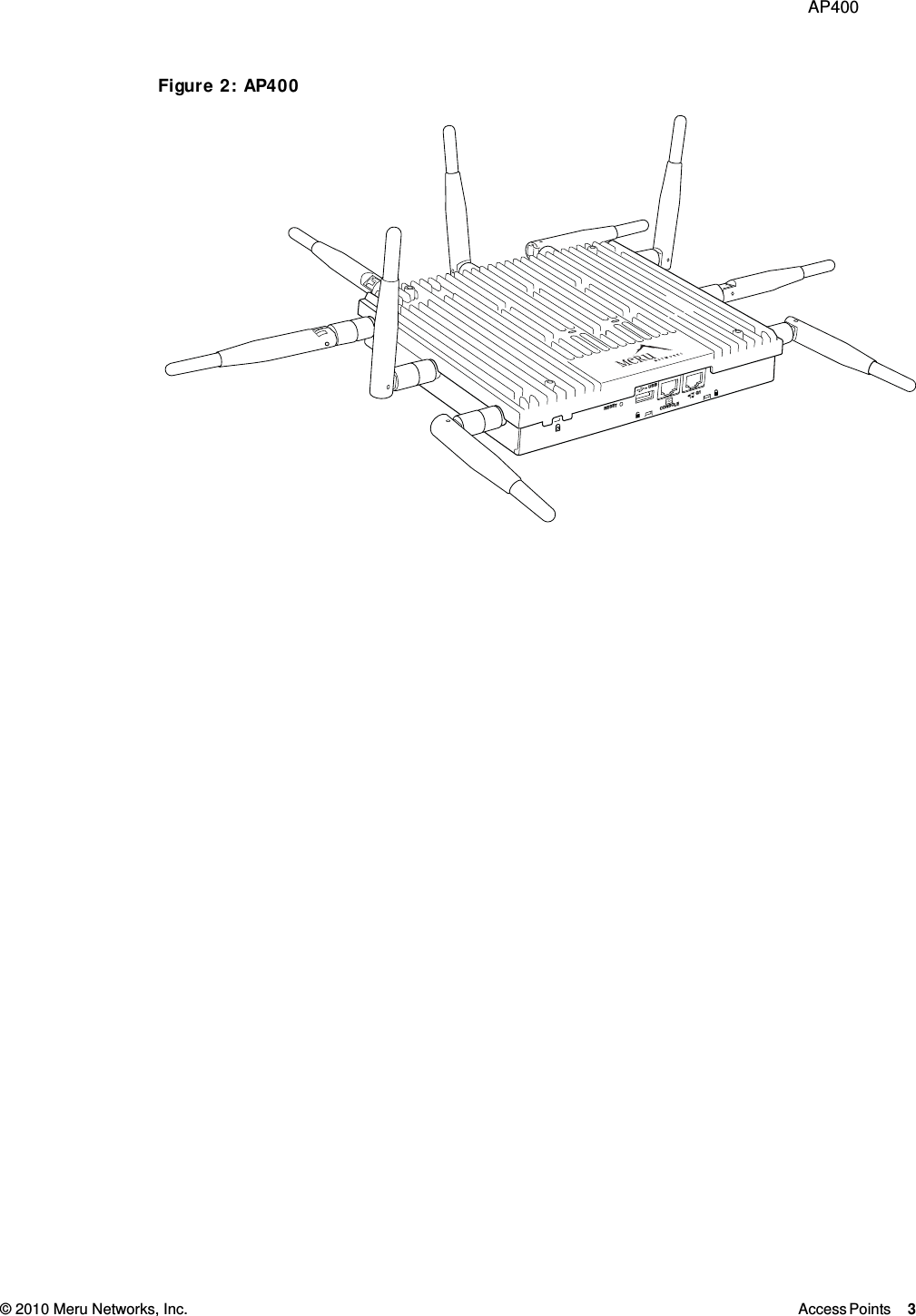
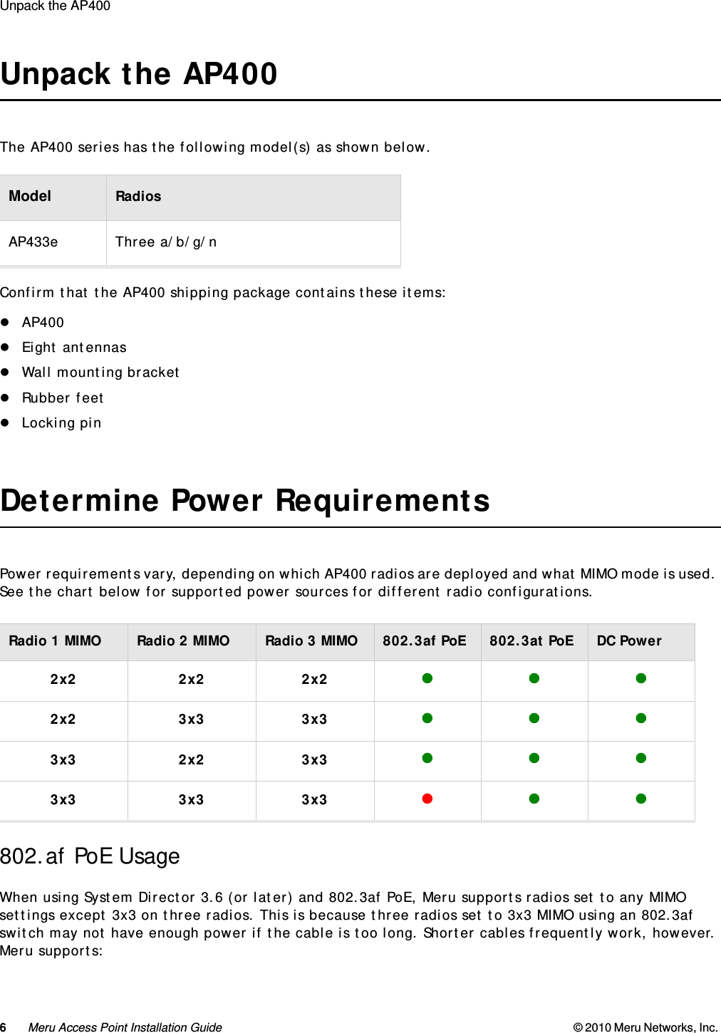
Meru Networks AP433E IEEE 802.11N ACCESS POINT User Manual AP400

Meru Networks Inc. IEEE 802.11N ACCESS POINT AP400

USERS MANUAL

Meru AP400Installation GuideCopyright © Meru Networks, Inc., 2003–2010. All rights reserved.Other names and brands may be claimed as the property of others.April 2011Document Number: 882-70016 Rev A Rel 4.1 Ver 1 AP400 Installation Guide
iii MERU NETWORKS, INC.Limited Product WarrantyThis Limited Product Warranty applies to the original end-user customer of the Meru product which you purchased for your own use, and not for resale (“Product”), from Meru Networks, Inc. (“Meru”) or its authorized reseller (“Reseller”).Limited Warranties—One-year limited hardware warranty:  Meru warrants to you that Meru hardware (other than Third Party Products as described below) will be free from defects in materials and workmanship for a one-year period after the date of delivery of the applicable product to you from Meru or its Reseller (the “Hardware Warranty Period”).  If Meru receives written notice from you of such defects during the Hardware Warranty Period, Meru will, at its option, either repair or replace Meru hardware that Meru determines to be defective.  Replacement products may be remanufactured units, and will be warranted for the remainder of the original Hardware Warranty Period, or if greater, for thirty days from delivery of such replacement.  Should Meru be unable to repair or replace the Meru hardware, Meru (or its Reseller, as applicable) will refund to you the purchase price of the Product.—90-Day Limited Software Warranty:  Meru warrants to you that, for a 90-day period after the date of delivery of the applicable product to you from Meru or its Reseller (the “Software Warranty Period”), when properly installed and used, (a) the media on which the Meru software is provided will be free from defects in materials or workmanship; and (b) the Meru software will substantially conform to the functional specifications in the applicable documentation.  If Meru receives written notice from you of a breach of this warranty during the Software Warranty Period and is able to reproduce the defect, Meru will, at its option, either repair or replace the defective Meru software.  Should Meru be unable to repair or replace the Meru software, Meru (or its Reseller, as applicable) will refund to you the purchase price of the Product.ExclusionsThe warranty on the Product shall not apply to defects resulting from the following:
iv Meru Access Point Installation Guide —Alteration or modification of the Product in any way, including without limitation configuration with software or components other than those supplied by Meru or integration with parts other than those supplied by Meru.—Abuse, damage or otherwise being subjected to problems caused by negligence or misapplication (including without limitation improper or inadequate maintenance or calibration), relocation of the products (including without limitation damage caused by use of other than Meru shipping containers), or use of the products other than as specified in the applicable Meru product documentation (including without limitation incompatible operating environments and systems), or improper site preparation or maintenance.—Damage as a result of accidents, extreme power surge, extreme electromagnetic field, acts of nature or other causes beyond the control of Meru.—Use of the Product with software, interfacing, parts or supplies not supplied by Meru.The warranty on the Product does not apply if the Product is sold, or in the case of software, licensed,  for free for evaluation or demonstration purposes.Meru expressly disclaims any warranty or obligation to support the Product for all operating environments – for example, as illustration and not limitation, Meru does not warrant or ensure interoperability of the Product with future telecommunica-tion systems or other future software or hardware.You understand and acknowledge that the Products may generate, use or radiate radio frequency energy and may interfere with radio communications and/or radio and television receptions if is not used and/or installed in accordance with the documentation for such products. WHILE MERU USES COMMERCIALLY REASONABLE EFFORTS TO ENSURE COMPLIANCE OF THE PRODUCTS WITH APPLICABLE UNITED STATES FEDERAL COMMUNICATIONS COMMISSION AND PROTECT AGAINST HARMFUL INTERFERENCES, YOU ACKNOWLEDGE AND AGREE THAT INTERFERENCES WITH RADIO COMMUNICATIONS AND/OR RADIO AND TELEVISION RECEPTIONS MAY OCCUR AND THAT MERU WILL NOT BE LIABLE FOR ANY DAMAGES OR INCONVENIENCE BASED ON SUCH INTERFERENCES. Third Party Products - The above Limited Warranties are exclusive of products manufactured by third parties (“Third Party Products”).  If such third party manu-facturer provides a separate warranty with respect to the Third Party Product, Meru will include such warranty in the packaging of the Meru Product.   Return proceduresTo obtain warranty service you must:  (a) obtain a return materials authorization number (“RMA#”) from Meru by contacting rmaadmin@merunetworks.com, and (b) deliver the Product, in accordance with the instructions provided by Meru, along with proof of purchase in the form of a copy of the bill of sale including the Product’s serial number, contact information, RMA# and detailed description of the defect, in either its original package or packaging providing the Product with a
v   degree of protection equivalent to that of the original packaging, to Meru at the address below.  You agree to obtain adequate insurance to cover loss or damage to the Product during shipment.   If you obtain an RMA# and return the defective Product as described above, Meru will pay the cost of returning the Product to Meru.  Otherwise, you agree to bear such cost, and prior to receipt by Meru, you assume risk of any loss or damage to the Product.  Meru is responsible for the cost of return shipment to you if the Meru Product is defective.Returned products which are found by Meru to be not defective, returned out-of-warranty or otherwise ineligible for warranty service will be repaired or replaced at Meru’s standard charges and shipped back to you at your expense.At Meru’s sole option, Meru may perform repair service on the Product at your facility, and you agree to provide Meru with all reasonable access to such facility and the Product, as required by Meru.  On-site repair service may be available and is governed by the specific terms of your purchase.All replaced parts, whether under warranty or not, are the property of Meru. Warranty limitationsTHE WARRANTIES SET FORTH ABOVE ARE EXCLUSIVE AND NO OTHER WARRANTY, WHETHER WRITTEN OR ORAL, IS EXPRESSED OR IMPLIED BY MERU, TO THE MAXIMUM EXTENT PERMITTED BY LAW.  THERE ARE NO OTHER WARRANTIES RESPECTING THE PRODUCT AND DOCUMENTATION AND SERVICES PROVIDED UNDER THIS AGREEMENT, INCLUDING WITHOUT LIMITATION ANY WARRANTY OF DESIGN, MERCHANTABILITY, FITNESS FOR A PARTICULAR PURPOSE (EVEN IF MERU HAS BEEN INFORMED OF SUCH PURPOSE), TITLE OR AGAINST INFRINGEMENT OF THIRD PARTY RIGHTS. IF ANY IMPLIED WARRANTY CANNOT BE DISCLAIMED UNDER APPLICABLE LAW, THEN SUCH IMPLIED WARRANTY SHALL BE LIMITED IN DURATION TO THE HARDWARE AND SOFT-WARE WARRANTY PERIODS DESCRIBED ABOVE. NO AGENT OF MERU IS AUTHORIZED TO ALTER OR EXCEED THE WARRANTY OBLIGA-TIONS OF MERU.MERU SPECIFICALLY DOES NOT WARRANT THAT THE MERU SOFTWARE WILL BE ERROR FREE OR OPERATE WITHOUT INTERRUPTION. THE REMEDIES IN THIS LIMITED PRODUCT WARRANTY ARE YOUR SOLE AND EXCLUSIVE REMEDIES, AND MERU’S SOLE AND EXCLUSIVE LIABILITY, FOR BREACH OF THE HARD-WARE OR SOFTWARE WARRANTY SET FORTH ABOVE.Limitations of LiabilityYou acknowledge and agree that the consideration which you paid to Meru does not include any consideration by Meru of the risk of consequential, indirect or inci-dental damages which may arise in connection with your use of, or inability to use, the Product.  THUS, MERU AND ITS RESELLER WILL NOT BE LIABLE FOR ANY INDI-RECT, INCIDENTAL, SPECIAL, PUNITIVE OR CONSEQUENTIAL DAMAGES, INCLUDING WITHOUT LIMITATION LOST PROFITS, LOST BUSINESS, LOST DATA, LOSS OF USE, OR
vi Meru Access Point Installation Guide COST OF COVER INCURRED BY YOU ARISING OUT OF OR RELATED TO YOUR PURCHASE OR USE OF, OR INABILITY TO USE, THIS PRODUCT OR THE SERVICES, UNDER ANY THEORY OF LIABILITY, WHETHER IN AN ACTION IN CONTRACT, STRICT LIABILITY, TORT (INCLUDING NEGLIGENCE) OR OTHER LEGAL OR EQUITABLE THEORY, EVEN IF MERU OR ITS RESELLER KNEW OR SHOULD HAVE KNOWN OF THE POSSIBILITY OF SUCH DAMAGES.  IN ANY EVENT, THE CUMULATIVE LIABILITY OF MERU OR ITS RESELLER FOR ALL CLAIMS WHATSOEVER RELATED TO THE PRODUCT OR THE SERVICE WILL NOT EXCEED THE PRICE YOU PAID FOR THE PRODUCT OR SERVICES GIVING RISE TO SUCH CLAIMS.THE LIMITATIONS SET FORTH HEREIN ARE INTENDED TO LIMIT THE LIABILITY OF MERU AND ITS RESELLERS AND SHALL APPLY NOTWITHSTANDING ANY FAILURE OF ESSEN-TIAL PURPOSE OF ANY LIMITED REMEDY.The jurisdiction applicable to you may not allow the limitations of liability or damages set forth above, in which case such limitation shall only apply to you to the extent permitted in such jurisdiction.Additional InformationThis Limited Product Warranty shall be governed by and construed in accordance with the laws of the State of California, U.S.A., exclusive of its conflict of laws prin-ciples.  The U.N. Convention on Contracts for the International Sale of Goods shall not apply.This Limited Product Warranty is the entire and exclusive agreement between you and Meru with respect to its subject matter, and any modification or waiver of any provision of this statement is not effective unless expressly set forth in writing by an authorized representative of Meru.All inquiries or claims made under this Limited Product Warranty must be sent to Meru at the following address:Meru Networks Inc.,894 Ross Drive, CA 94087, USATel:  408-215-5300Fax:  408-215-5301Email:  support@merunetworks.com
  © 2010 Meru Networks, Inc. Contents vii ContentsAbout This Guide .  .  .  .  .  .  .  .  .  .  .  .  .  .  .  .  .  .  .  .  .  .  .ixAudience  .   .   .   .   .   .   .   .   .   .   .   .   .   .   .   .   .   .   .   .   .   .   .   .   .   ixOther Sources of Information  .   .   .   .   .   .   .   .   .   .   .   .   .   .   .   .   .   .   ixMeru Publications .   .   .   .   .   .   .   .   .   .   .   .   .   .   .   .   .   .   .   .   .  ixWebsite Resources    .   .   .   .   .   .   .   .   .   .   .   .   .   .   .   .   .   .   .   .   ixExternal References  .   .   .   .   .   .   .   .   .   .   .   .   .   .   .   .   .   .   .   .   xTypographic Conventions    .   .   .   .   .   .   .   .   .   .   .   .   .   .   .   .   .   .   .   xContacting Meru    .   .   .   .   .   .   .   .   .   .   .   .   .   .   .   .   .   .   .   .   .   .  xiCustomer Services and Support  .   .   .   .   .   .   .   .   .   .   .   .   .   .   .   .  xiChapter 1Access Points.  .  .  .  .  .  .  .  .  .  .  .  .  .  .  .  .  .  .  .  .  .  .  .  . 1AP400  .   .   .   .   .   .   .   .   .   .   .   .   .   .   .   .   .   .   .   .   .   .   .   .   .   .   2Chapter 2Installing AP400   .  .  .  .  .  .  .  .  .  .  .  .  .  .  .  .  .  .  .  .  .  .  . 5Safety Precautions .   .   .   .   .   .   .   .   .   .   .   .   .   .   .   .   .   .   .   .   .   .   5Unpack the AP400 .   .   .   .   .   .   .   .   .   .   .   .   .   .   .   .   .   .   .   .   .   .   6Determine Power Requirements  .   .   .   .   .   .   .   .   .   .   .   .   .   .   .   .   .   6802.af PoE Usage  .   .   .   .   .   .   .   .   .   .   .   .   .   .   .   .   .   .   .   .   .   6802.3at PoE Usage.   .   .   .   .   .   .   .   .   .   .   .   .   .   .   .   .   .   .   .   .   7Installation Requirements   .   .   .   .   .   .   .   .   .   .   .   .   .   .   .   .   .   .   .   7Additional Equipment    .   .   .   .   .   .   .   .   .   .   .   .   .   .   .   .   .   .   .   8Install the AP400   .   .   .   .   .   .   .   .   .   .   .   .   .   .   .   .   .   .   .   .   .   .   8Select a Location  .   .   .   .   .   .   .   .   .   .   .   .   .   .   .   .   .   .   .   .   .   8Attach the Provided Antennas.   .   .   .   .   .   .   .   .   .   .   .   .   .   .   .   .   9Install the Access Point .   .   .   .   .   .   .   .   .   .   .   .   .   .   .   .   .   .   .  10Check AP400 LED Activity   .   .   .   .   .   .   .   .   .   .   .   .   .   .   .   .   .   .   .  14Where to Go From Here .   .   .   .   .   .   .   .   .   .   .   .   .   .   .   .   .   .   .   .  15Cautions and Warnings  .  .  .  .  .  .  .  .  .  .  .  .  .  .  .  .  .  .  .  17Cautions   .   .   .   .   .   .   .   .   .   .   .   .   .   .   .   .   .   .   .   .   .   .   .   .   .  17Warnings  .   .   .   .   .   .   .   .   .   .   .   .   .   .   .   .   .   .   .   .   .   .   .   .   .  19Regulatory Information .  .  .  .  .  .  .  .  .  .  .  .  .  .  .  .  .  .  .  23For AP400 .   .   .   .   .   .   .   .   .   .   .   .   .   .   .   .   .   .   .   .   .   .   .   .   .  23Radio  .   .   .   .   .   .   .   .   .   .   .   .   .   .   .   .   .   .   .   .   .   .   .   .   .  23EMC.   .   .   .   .   .   .   .   .   .   .   .   .   .   .   .   .   .   .   .   .   .   .   .   .   .  23Safety .   .   .   .   .   .   .   .   .   .   .   .   .   .   .   .   .   .   .   .   .   .   .   .   .  23USA .   .   .   .   .   .   .   .   .   .   .   .   .   .   .   .   .   .   .   .   .   .   .   .   .   .   .  25
viii Meru Access Point Installation Guide © 2010 Meru Networks, Inc. Underwriters Laboratories   .   .   .   .   .   .   .   .   .   .   .   .   .   .   .   .   .    25FCC Radiation Exposure Statement   .   .   .   .   .   .   .   .   .   .   .   .   .   .    25Radio Frequency Interference Requirements .   .   .   .   .   .   .   .   .   .   .    25Canada. Industry Canada (IC)    .   .   .   .   .   .   .   .   .   .   .   .   .   .   .   .   .    27Europe—EU Declaration of Conformity and Restrictions    .   .   .   .   .   .   .   .    29IEEE 802.11a Restrictions.   .   .   .   .   .   .   .   .   .   .   .   .   .   .   .   .   .    31EEE 802.11b/g Restrictions  .   .   .   .   .   .   .   .   .   .   .   .   .   .   .   .   .    31Japan.   .   .   .   .   .   .   .   .   .   .   .   .   .   .   .   .   .   .   .   .   .   .   .   .   .    32Singapore  .   .   .   .   .   .   .   .   .   .   .   .   .   .   .   .   .   .   .   .   .   .   .    32Manufacturing Information   .   .   .   .   .   .   .   .   .   .   .   .   .   .   .   .   .   .    32Supported PoEs  .  .  .  .  .  .  .  .  .  .  .  .  .  .  .  .  .  .  .  .  .  .  . 33Supported Power Over Ethernet Devices for Meru APs .   .   .   .   .   .   .   .   .    33
© 2010 Meru Networks, Inc.About This Guide About This Guide ix  About This GuideThis guide provides installation instructions for the Meru AP400s, which includes both the AP400 and the AP400i models. The term access point is used interchangeably throughout this document to apply to any model when there are no differences among the models.AudienceThis guide is intended for anyone installing Meru Wireless LAN System Access Points (APs).Other Sources of InformationAdditional information is available in the following Meru publications, Web site, and external references.Meru PublicationsMeru System Director Release NotesMeru System Director Getting Started GuideMeru Controller Installation GuideMeru System Director Command ReferenceMeru System Director Configuration GuideWebsite ResourcesFor the first 90 days after you buy a Meru controller, you have access to online support. If you have a support contract, you have access for the length of the contract. See this web site for information such as:Meru System Director Release NotesKnowledge Base (Q&A)
© 2010 Meru Networks, Inc.About This Guide About This Guide x  DownloadsOpen a ticket or check an existing oneCustomer Discussion ForumThe URL is: http://support.merunetworks.comMeru System Director Getting Started GuideMeru Controller Installation GuideMeru System Director Release NotesMeru System Director Configuration GuideMeru System Director Command ReferenceExternal ReferencesStevens, W. R. 1994. TCP/IP Illustrated, Volume 1, The Protocols. Addison-Wesley, Reading, Mass.Gast, M.S. 2002. 802.11 Wireless Networks, The Definitive Guide. O’Reilly and Associates, Sebastopol, Calif.Typographic ConventionsThis document uses the following typographic conventions to help you locate and identify information: Note:Provides extra information, tips, and hints regarding the topic.Caution!Identifies important information about actions that could result in damage to or loss of data, or could cause the application to behave in unexpected ways.Warning!   Identifies critical information about actions that could result in equipment failure or bodily harm.
© 2010 Meru Networks, Inc.About This Guide About This Guide xi  Contacting Meru You can visit Meru Networks, Inc. on the Internet at this URL:http://www.merunetworks.comCustomer Services and SupportFor assistance, contact Meru Customer Services and Support 24 hours a day at+1-888-637-8952 (+1-888-Meru-WLA(N)) or +1-408-215-5305. Email can be sent to support@merunetworks.com.Meru Networks, Inc. Customer Services and Support provide end users and channel partners with the following:Telephone technical supportSoftware update supportSpare parts and repair serviceRMA ProceduresContact Meru Customer Services and Support for a Return Material Authorization (RMA) for any Meru equipment.Please have the following available when making a call:Company and contact informationEquipment model and serial numbersMeru software release and revision numbers (for example, 3.0.0-35)A description of the symptoms the problem is manifestingNetwork configuration
© 2010 Meru Networks, Inc.About This Guide About This Guide xii
  © 2010 Meru Networks, Inc. Access Points 1  Chapter 1Access PointsAccess Points contain radio devices that communicate with the Meru Controller and form the wireless LAN (WLAN). The Meru Controller and Access Points connect to the site’s wired LAN through wired switches. Wireless clients associate with the Access Points as they roam throughout the WLAN. As such, they are an extension of the wired LAN, providing the wireless benefits of client mobility, enhanced access, and dynamic network configuration. Figure 1: Wireless LAN Connected to NetworkMeru AP
2Meru Access Point Installation Guide © 2010 Meru Networks, Inc. AP400  AP400The AP400 Access Point series delivers high performance, full-speed, Wi-Fi certified 802.11n based on draft 2.0 connectivity while simultaneously supporting legacy 802.11a/b/g devices. AP400 is available in the configurations shown below.AP400 ConfigurationsFeatures for the AP400 include:802.11n support with channel bonding in both 2.4GHz and 5GHz frequency bands. Channel bonding combines two 20Mhz channels into a single-wide 40Mhz channel for increased throughput.Dual-band external antenna options optimized for MIMO mode.Plug and Play deployment using centralized controller platforms.Multi-layered security including standard WPA2, 802.11i security (such as automatic traffic inspection).Each of these Access points may be powered by a standard 802.3af or 802.3at PoE device. However, in order to utilize all three radios in 3x3 operation, 802.3at PoE is required.Air Traffic Control technology for 802.11n devices and legacy a/b/g devices 3x3 MIMO with 3 chains and 3 receive chains, delivering two spatial streams Channel span architecture which requires no channel planning or configurationEight standard multiband, omni-directional antennas for AP433e.Powered by 5 volt DC input, 802.3af compliant PoE device, or draft 802.3at compliant PoE device.Model ConfigurationAP433e Three dual-band 802.11n radios with 3x3 MIMO and external antennas.
 AP400 © 2010 Meru Networks, Inc. Access Points 3  Figure 2: AP400RESETCONSOLEG1USB
4Meru Access Point Installation Guide © 2010 Meru Networks, Inc. AP400
 Safety Precautions © 2010 Meru Networks, Inc. Installing AP400 5 Chapter 2Installing AP400This chapter describes how to install and configure an AP400. It contains the following sections:Safety PrecautionsUnpack the AP400Determine Power RequirementsInstallation RequirementsInstall the AP400Check AP400 LED ActivityCheck AP400 LED ActivityWhere to Go From HereSafety PrecautionsIMPORTANT—Read and follow the regulatory instructions in Appendix B before installing and operating this product.If an optional power supply is used, it must be one supplied by Meru Networks.The AP400 is intended only for installation in Environment A as defined in IEEE 802.3af. All intercon-nected equipment must be contained within the same building, including the interconnected equip-ment's associated LAN connection.
6Meru Access Point Installation Guide © 2010 Meru Networks, Inc. Unpack the AP400  Unpack the AP400The AP400 series has the following model(s) as shown below.Confirm that the AP400 shipping package contains these items:AP400Eight antennasWall mounting bracketRubber feetLocking pinDetermine Power RequirementsPower requirements vary, depending on which AP400 radios are deployed and what MIMO mode is used. See the chart below for supported power sources for different radio configurations.802.af PoE UsageWhen using System Director 3.6 (or later) and 802.3af PoE, Meru supports radios set to any MIMO settings except 3x3 on three radios. This is because three radios set to 3x3 MIMO using an 802.3af switch may not have enough power if the cable is too long. Shorter cables frequently work, however. Meru supports:Model RadiosAP433e Three a/b/g/nRadio 1 MIMO Radio 2 MIMO Radio 3 MIMO 802.3af PoE 802.3at PoE DC Power2x2 2x2 2x2 2x2 3x3 3x3 3x3 2x2 3x3 3x3 3x3 3x3 
 Installation Requirements © 2010 Meru Networks, Inc. Installing AP400 7 Single or dual 3x3 radiosThree 2x2 radiosThree radios with one set to 2x2 and the other two set to 3x3 802.3at PoE UsageWhen using System Director 3.6 (or later) and 802.3at, all possible configurations are supported. For a list of supported PoEs, see the appendix Supported Power Over Ethernet Devices for Meru APsInstallation RequirementsAn array of holes on the mounting bracket allows the AP400 to be mounted on the wall and over junc-tion boxes or molly bolts. There are holes for passing the PoE Ethernet or external power supply cable through the bracket if the bracket is mounted on a junction box.The AP400 has a security cable slot so you can lock the AP400 with a standard security cable, such as those used to secure laptop computers.Purchase optional mounting kits to mount the AP400 either from the ceiling or inside an enclosure: Above Suspended Ceiling Mounting Kit (T-Bar Hanger): ACC-MNT-ASCMKITAbove hanging ceiling tiles. Suitable for use in environmental air space in accordance with the Section 300-22(c) of the National Electric Code and Sections 2- 128.12 - 010 (3) and 12 - 100 of the Canadian Electrical Code. Part 1. C22. 1. To complete AP400 installation, you need the items listed below.Installation Type Items RequiredHorizontal mounting NoneVertical mounting over a wall studTwo #6 x 2" wood screws for a wood stud; or Two #6 x 1½” metal screws for a metal studMounting bracketVertical mounting on sheetrockTwo #6 x 1" screwsTwo #4-6 x 7/8” ribbed plastic wall anchorsMounting bracket
8Meru Access Point Installation Guide © 2010 Meru Networks, Inc. Install the AP400  Additional EquipmentA power source is needed to power the AP400. See Determine Power Requirements.Install the AP400Select a LocationAttach the Provided AntennasInstall the Access PointSelect a LocationAll AP400 interconnected equipment, including the associated LAN connection, must be contained within the same building. In addition, the AP400 location should meet the following conditions:Relatively unobstructed access to the stations the AP serves. Select a location with minimal physical obstructions between the AP and the wireless stations. In an office with cubicles, mounting the APs below a hanging ceiling (plenum is supported) or the wall near the ceiling provides the least obstructed communications path. On a wall, orient the AP400 horizontally so that you can read the Meru logo without tilting your head at 90 degrees - this orientation provides optimum MIMO performance.Access to wall outlet or a to a Power over Ethernet (PoE) connection to the network switch servicing the controller.We recommend planning for about 50 clients per radio (or per interference region) if you plan to use Virtual Port and plan to have phones as clients. For a data-only installation, plan up to 128 clients per radio. Refer to the Meru Deployment Guides on the support site for more information.AP400 is designed to provide 360 degree omni-directional coverage as illustrated below. Plan place-ment with this pattern in mind.Horizontal mounting below a hanging ceilingTwo caddy fastenersTwo plastic spacersTwo keps nuts (with attached lock washer)Mounting bracketMounting above a ceiling tile Mounting bracket ACC-MNT-ASCMKITInstallation Type Items Required
 Install the AP400 © 2010 Meru Networks, Inc. Installing AP400 9 Figure 3: Coverage Pattern for AP400 When Ceiling MountedMost installations receive the best coverage using the following guidelines:Install APs toward the center of the building.Place APs about 80 feet apart.Do not install APs near metal objects, such as heating ducts, metal doors, or electric service panels.For best coverage, orient antennas as shown in Figure 6.Attach the Provided AntennasAll AP400s have eight external antenna ports, labeled A1 - A8. These units operate with eight antennas attached, even though some configurations don’t use all eight. Instead of attaching an antenna, you can cap unused antenna connectors with 50 ohm Reverse Polarity SMA terminators. (For a list of approved terminators, see http://support.merunetworks.com/.) Meru-supplied antennas are suitable only for indoor use. To achieve the best performance from your AP400, position antennas at a 90 degree angles relative to each other as shown in Figure 6. (The antennas do not have to be oriented exactly as shown in the figure, but it is important to maintain the relative angles.) If for some reason you are unable to maintain those angles, the network will still operate, but you may experience up to a 20% drop in throughput depending on the antenna orientation.ceilingfloor
10 Meru Access Point Installation Guide © 2010 Meru Networks, Inc. Install the AP400  Figure 6: AP400 Antennas in Ceiling and Wall Mount ConfigurationDo not leave any antenna connectors unterminated. All connectors on the AP must be terminated with antennas or with 50 ohm Reverse Polarity SMA terminators.The attached antennas must be the same model; if you replace one antenna with a different type, replace them all.Install the Access PointAP400 ships with a mounting bracket included in the box. This bracket is intended for installation as a wall-mount; for mounting on a ceiling, no mount is typically required. See the following sections for more specific details.Mount AP400 Horizontally on a ShelfMount AP400 Vertically on a WallMount AP400 Below a Suspended CeilingMount AP400 Above a Suspended Ceiling (Plenum)Mount AP400 Horizontally on a ShelfWhen mounting an AP400 horizontally, no mounting bracket is required. Be sure to position the antennas vertically when an AP400 sits on a surface. In order to ensure that the AP400 does not shift much, attach the rubber feet provided in the box to the bottom of the AP.Mount AP400 Vertically on a WallTo mount an AP400 on a wall:RESETCONSOLEG1USB
 Install the AP400 © 2010 Meru Networks, Inc. Installing AP400 11 1. Using the holes on the mounting bracket itself as a guide, mark the location on the wall for the AP bracket mounting screws. If possible, center the mounting screws on a wall stud. (If mounting on a wall stud is impossible, use plastic wall anchors on the remaining screws.)2. Orient the AP400 horizontally so that you can read the Meru logo without tilting your head at 90 degrees - this orientation provides optimum MIMO performance.3. Drill holes at the locations you marked:—3/16-inch holes if you are using plastic anchors—1/8-inch holes if you are using only the screws4. If you are using plastic anchors, install them in the holes.5. Screw in the screws most of the way.6. Mount the bracket on the screws, placing the circular portion of the keyhole mounts over the screw heads and sliding the bracket down.Figure 7: Mounting the AP to the Bracket7. Connect one end of the Ethernet cable to the switch and the other end to the AP400 Ethernet port.Figure 8: Ports and Unlock Mechanism for the AP4008. If you are not using a PoE device, connect an external power supply to the power connector and plug it into the wall.Caution!Be sure to connect the Ethernet cable to the Ethernet port; the cable can mistakenly be plugged into the Console port. If you do this, the AP won’t power up.RESETUSBCONSOLEG1ConsoleportEthernetportUSBport00260
12 Meru Access Point Installation Guide © 2010 Meru Networks, Inc. Install the AP400  Mount AP400 Below a Suspended CeilingThe brackets on the bottom of the AP400 allow it to be mounted directly to a ceiling T-bar (see Figure 8). Note that the AP lock must be disabled by sliding the locking key (provided in the box) into the unlock hole on the side of the AP shown in Figure 7 in order to clip the AP in place.Figure 9: Mounting AP400 to a Suspended Ceiling RailTo mount an AP400 below a suspended ceiling:1. Determine the location on the ceiling rail where the AP will be mounted and remove the ceiling tiles.2. Verify that the AP is unlocked using the locking key on the unlock mechanism (on the same side as the Ethernet ports).3. Press the AP400 against the T-bar at a slight angle and then rotate into place, as indicated in Figure 8. You should hear it snap in place.4. For each antenna, loosen the knurled ring at the base of the antenna, orient the antenna and then retighten the ring.5. Connect one end of the PoE Ethernet cable to the AP’s Ethernet port (see Figure 9).Caution!Be sure to connect the Ethernet cable to the Ethernet port; the cable can mistakenly be plugged into the Console port. If you do this. the AP won’t power up.T-bar(in ceiling)00261
 Install the AP400 © 2010 Meru Networks, Inc. Installing AP400 13 Figure 10: Ports and Unlock Mechanism for the AP400RESETUSBCONSOLEG1ConsoleportEthernetportUSBport00260
14 Meru Access Point Installation Guide © 2010 Meru Networks, Inc. Install the AP400  Mount AP400 Above a Suspended Ceiling (Plenum)Use the optional T-bar box hanger mounting kit to mount the AP400 above suspended ceiling T-rails (see Figure 10). The installation attaches the T-bar box hanger to the ceiling rails and then the AP400 attaches to the T-bar box hanger. Note that an AP400 mounted above the ceiling has about 2-3 dBm less RF coverage than an AP400 mounted under the ceiling.Figure 11: AP400 Mounted Above a Suspended Ceiling Face Down The AP400 with the metal enclosure exposed meets the requirements for fire resistance and low smoke-generating characteristics required by Section 300-22(C) of the National Electrical Code (NEC) for installation in a building’s environmental air space.You may need to modify thicker tiles to support this installation.To mount an AP400 above the ceiling with the optional T-bar kit, follow these steps:1. Determine the location on the ceiling rails where the AP will be mounted and remove the ceiling tile.2. Unpack the T-bar hanger kit and attach the legs to the main support.3. Attach the square bracket to the underside of the main support bar using the screws provided.Warning!   When installed in air-handling spaces, such as above a suspended ceiling, power the AP400 only with a PoE, not a power supply.Warning!   Any Fast Ethernet (FE) cables installed in air-handling spaces should be suitable under NEC Article 800.50 and marked accordingly for use in plenums and air-handling spaces with regard to smoke propagation, such as CL2-P, CL3-P, MPP (Multi Purpose Plenum), or CMP (Communications Plenum). Use Ethernet cable that meets the requirements for operating in plenums and environmental air space in accordance with Section 300-22(C) of the NEC.
 Check AP400 LED Activity © 2010 Meru Networks, Inc. Installing AP400 15 4. Verify that the AP400 is unlocked using the locking key.5. Brace your hand against the back of the main support bar and press the AP400 against the square bracket in a similar manner to that indicated in Figure 8.6. Twist until the AP400 clicks into place. If desired, you can now lock the AP using the locking key.7. Mount the bracket and AP in the desired location by sliding the support arms onto the ceiling T-bars.8. For each antenna, loosen the knurled ring at the base of the antenna, point the antenna down, then retighten the ring.9. Connect one end of the PoE Ethernet cable to the Ethernet connector.10. Check that the AP400 is operating correctly before replacing the ceiling tile. Verify correct operating using the LEDs, as shown in Check AP400 LED Activity.Check AP400 LED ActivityWhen AP400 first connects to the controller (and any time the access point is rebooted), the AP initial-izes and is then programmed by the controller. When the AP first powers up, all LEDs are green.Figure 12: AP400 Status LEDsAfter the AP400 is connected, check the status of the LEDs. The functions of the LEDs are described below.Caution!Be sure to connect the Ethernet cable to the Ethernet port; the cable can mistakenly be plugged into the Console port. If you do this. the AP won’t power up.Note:Use a shielded Cat 5e (or greater) Ethernet cable in order to comply with international electromagnetic emissions limits.RESETCONSOLEG1USBLEDs00259ActivityPower
16 Meru Access Point Installation Guide © 2010 Meru Networks, Inc. Where to Go From Here  AP400 LED DescriptionsChange LED Appearance If you want to change the appearance of the LEDS, follow these steps:1. From the controller, click Configuration > Devices > AP, and then select the AP.2. Select one of these settings for the LED Mode setting:—Normal: LEDs are as described above—Blink: Sets all LEDs flashing; this is useful to locate an AP—Dark: Turns off all LEDs3. Click OK.Where to Go From HereNow that the AP400 is installed, refer to the Meru System Director Getting Started Guide for instruc-tions on initializing the hardware. Return to this chapter to check the status of the LEDs once the WLAN is operational.LED Function TroubleshootingPower off—no powergreen—presence of powerStatusoff—no powergreen—booting stage 1blinking green and off—booting stage 2blinking green and white—discovering the controllerblinking green and blue—downloading a configuration from the controllerblinking blue and off—AP is online and enabled, working stateblinking red and yellow—failure; consult controller for alarm stateIf the status LED is blinking red and yellow, there is an alarm on the AP. Determine what the alarm is by clicking Monitor > Dashboard > Alarms and looking at the AP alarms. You can also use the CLI commands show alarm and show log.
 Cautions © 2010 Meru Networks, Inc. Cautions and Warnings  17Appendix ACautions and WarningsThe cautions and warnings that appear in this manual are listed below in English, German, French, and Spanish.CautionsA Caution calls your attention to a possible hazard that can damage equipment. "Vorsicht” weist auf die Gefahr einer möglichen Beschädigung des Gerätes in.Une mise en garde attire votre attention sur un risque possible d'endommagement de l'équipement. Ci-dessous, vous trouverez les mises en garde utilisées dans ce manuel.Un mensaje de precaución le advierte sobre un posible peligro que pueda dañar el equipo. Las siguientes son precauciones utilizadas en este manual.Caution!When changing the orientation of the antennas, be sure to slightly loosen the knurled ring before moving the antenna. Retighten the ring afterward. Otherwise, you might damage the internal cabling in the AP.Vorsicht!Bei einer Neuausrichtung der Antennen muss vor Bewegung der Antenne der Rändelring leicht gelockert werden. Anschließend den Ring wieder festziehen. Anderenfalls können die internen Kabel im AP beschädigt werden.Mise en gardeEn cas de modification d’orientation des antennes, veiller à desserrer légèrement la bague moletée avant de réorienter l’antenne. Resserrer ensuite la bague, faute de quoi le câblage interne du point d’accès pourrait être endommagé.Precaución!Al cambiar la orientación de las antenas, asegúrese de aflojar ligeramente el anillo estriado antes de mover la antena. Luego vuelva a apretar el anillo. De otro modo, podría dañar el cableado interno del punto de acceso.
18 Meru Access Point Installation Guide © 2010 Meru Networks, Inc. Cautions Caution!Be sure to connect the Ethernet cable to the Ethernet port; the cable can mistakenly be plugged into the Console port.Vorsicht!Darauf achten, dass das Ethernetkabel am Ethernetanschluss und nicht versehentlich am Konsolenanschluss angeschlossen wird.Mise en gardeVeiller à bien connecter le câble Ethernet au port Ethernet et non pas au port Console.Precaución!Asegúrese de conectar el cable Ethernet al puerto Ethernet, porque por error se puede enchufar en el puerto de la consola.Caution!The radiated output power of the access points is well below the FCC radio frequency exposure limits. However, the Meru Access Point should be used in such a manner that the potential for human contact during normal operation is minimized. To avoid the possibility of exceeding the FCC radio frequency exposure limits, you should keep a distance of at least 20 cm between you (or any other person in the vicinity) and the Access Point antennas.Vorsicht!Die abgestrahlte Ausgangsleistung von Geräten von Meru Networks, Inc. liegt weit unter den Hochfrequenz-Expositionsgrenzwerten der FCC. Die Meru Access Point Zugangspunkte von Meru Networks, Inc. sollten jedoch so verwendet werden, dass das Potenzial für Kontakt mit Menschen während des normalen Betriebs auf ein Mindestmaß beschränkt wird. Um die Möglichkeit einer Überschreitung der FCC-Hochfrequenz-Expositionsgrenzwerte zu vermeiden, ist ein Abstand von mindestens 20 cm zwischen Ihnen (bzw. einer anderen Person in der Nähe) und den Zugangspunkt-Antennen zu wahren.Mise en gardeLa puissance de rayonnement émise par les équipements Meru Networks, Inc. est très inférieure aux limites d'exposition aux fréquences radio définies par la FCC. Toutefois, les points d'accès de la série Meru Access Point de Meru Networks, Inc. doivent être utilisés de façon à éliminer tout risque de contact humain en fonctionnement normal. Pour éviter de dépasser les limites d'exposition aux fréquences radio définies par la FCC, il est impératif de préserver en permanence une distance supérieure ou égale à 20 cm entre l'utilisateur (ou toute personne se trouvant à proximité) et les antennes du point d'accès.Precaución!La potencia de radiación de los dispositivos de Meru Networks, Inc. está muy por debajo de los límites de exposición a radiofrecuencia estipulados por la FCC. No obstante, los puntos de acceso de la serie Meru Access Point de Meru Networks, Inc. deben usarse de tal manera que se minimice la posibilidad de contacto para el usuario durante la operación normal. Para evitar la posibilidad de exceder los límites de exposición a radiofrecuencia establecidos por la FCC, el usuario (o cualquier otra persona en torno) debe mantenerse a una distancia de al menos 20 cm respecto a las antenas del punto de acceso.
 Warnings © 2010 Meru Networks, Inc. Cautions and Warnings  19WarningsA warning calls your attention to a possible hazard that can cause injury or death. The following are the warnings used in this manual."Achtung" weist auf eine mögliche Gefährdung hin, die zu Verletzungen oder Tod führen können. Sie finden die folgenden Warnhinweise in diesem Handbuch:Un avertissement attire votre attention sur un risque possible de blessure ou de décès. Ci-dessous, vous trouverez les avertissements utilisés dans ce manuel.Una advertencia le llama la atención sobre cualquier posible peligro que pueda ocasionar daños personales o la muerte. A continuación se dan las advertencias utilizadas en este manual.Caution!Exposure to Radio Frequency Radiation.The installer of this radio equipment must ensure that the antenna is located or pointed such that it does not emit an RF field in excess of Health Canada limits for the general population; consult Safety Code 6, obtainable from Health Canada’s website http://www.hc-sc.gc.ca/rpb. Vorsicht!Exposure to Radio Frequency Radiation.The installer of this radio equipment must ensure that the antenna is located or pointed such that it does not emit an RF field in excess of Health Canada limits for the general population; consult Safety Code 6, obtainable from Health Canada's website http://www.hc-sc.gc.ca/rpb.Mise en gardeExposition aux rayonnements à fréquence radioélectriqueL'installateur de cet équipement radio doit veiller à positionner et orienter l'antenne de telle sorte qu'elle n'émette pas un champ radioélectrique supérieur aux limites définies par Santé Canada pour la population générale. Consulter le Code de sécurité n° 6, disponible sur le site Web de Santé Canada à l'adresse http://www.hc-sc.gc.ca/rpb. Precaución!Exposición a la radiación de radiofrecuencia.El instalador de este equipo de radio debe cerciorarse de que la antena está local-izada u orientada de tal manera que no emita un campo de radiofrecuencia superior a los límites estipulados por Health Canada para la población; consulte el Código de Seguridad 6 que podrá encontrar en el página web de Health Canada, http://www.hc-sc.gc.ca/rpb.
20 Meru Access Point Installation Guide © 2010 Meru Networks, Inc. Warnings Warning!   With plastic covers removed, this product is suitable for use in environmental air space in accordance with the Section 300-22(c) of the National Electric Code and Sections 2- 128.12 - 010 (3) and 12 - 100 of the Canadian Electrical Code. Part 1. C22. 1. For other countries, consult local authorities for regulations.Achtung!   Bei abgenommener Kunststoffabdeckung ist dieses Produkt zur Verwendung in einem Umgebungsluftraum gemäß Abschnitt 300-22(c) des National Electric Code und Abschnitt 2- 128.12 - 010 (3) und 12 - 100 des Canadian Electrical Code Teil 1. C22.1 geeignet. Die Vorschriften für andere Länder sind bei den örtlichen Behörden erhältlich.AvertissementSous réserve que ses couvercles de plastique soient déposés, cet appareil est adapté à une utilisation dans les vides de construction des bâtiments selon la section 300-22(c) du code NEC (National Electric Code) et les sections 2- 128.12 - 010 (3) et 12 - 100 du Code électrique du Canada, partie 1. C22. 1. Pour tous les autres pays, consulter les organismes de réglementation locaux.AdvertenciaUna vez desprendidas las cubiertas de plástico, este producto es adecuado para su uso en el espacio aéreo circundante en conformidad con la sección 300-22(c) del National Electric Code (Código Eléctrico Nacional de EE.UU.) y las secciones 2- 128.12 - 010 (3) y 12 - 100 del Código Eléctrico de Canadá. Parte 1. C22. 1. En otros países, consulte a las autoridades locales competentes para informarse acerca de las normativas vigentes.Warning!   Any Fast Ethernet (FE) cables installed in air-handling spaces should be suitable under NEC Article 800.50 and marked accordingly for use in plenums and air-handling spaces with regard to smoke propagation, such as CL2-P, CL3-P, MPP (Multi Purpose Plenum), or CMP (Communications Plenum).Achtung!   Alle Fast-Ethernet (FE)-Kabel, die in Lüftungsräumen installiert werden, sollten gemäß NEC Artikel 800.50 geeignet sein und entsprechend zur Verwendung in Hohlräumen (Plenum) und Lüftungsräumen im Hinblick auf Rauchausbreitung gekennzeichnet sein, z.B. CL2-P, CL3-P, MPP (Multi Purpose Plenum) oder CMP (Communications Plenum).AvertissementLes câbles Fast Ethernet (FE) installés dans un vide d’air doivent correspondre aux critères de l’article 800.50 du code NEC et identifiés en conséquence comme adaptés à une utilisation dans les vides de construction des bâtiments en matière de propagation de la fumée (marquages CL2-P, CL3-P, MPP (Multi Purpose Plenum) ou CMP (Communications Plenum)).AdvertenciaTodos los cables Fast Ethernet (FE) instalados en espacios aéreos deben cumplir con el artículo 800.50 del NEC y estar marcados adecuadamente para su uso en espacios aéreos y plenums en lo concerniente a la propagación de humo, tales como CL2-P, CL3-P, MPP (Plenum multifuncional), o CMP (Plenum de comunicaciones).
 Warnings © 2010 Meru Networks, Inc. Cautions and Warnings  21Warning!   Inside antennas must be positioned to observe minimum separation of 20 cm. (~ 8 in.) from all users and bystanders. For the protection of personnel working in the vicinity of inside (downlink) antennas, the following guidelines for minimum distances between the human body and the antenna must be observed. The installation of the indoor antenna must be such that, under normal conditions, all personnel cannot come within 20 cm. (~ 8.0 in.) from any inside antenna. Exceeding this minimum separation will ensure that the employee or bystander does not receive RF-exposure beyond the Maximum Permissible Exposure according to FCC CFR 47, section 1.1310 i.e. limits for General Population/Uncontrolled Exposure.Achtung!   Innenantennen müssen so positioniert werden, dass ein Mindestabstand von 20 cm (ca. 8 Zoll) zu allen Benutzern und anderen Personen gewahrt wird. Zum Schutz von Personal, das in der Nähe von Innenantennen (Downlink) arbeitet, sind die folgenden Richtlinien für Mindestabstand zwischen dem menschlichen Körper und der Antenne zu beachten. Die Innenantenne muss so installiert werden, dass sich unter normalen Bedingungen kein Personal bis auf weniger als 20 cm (ca. 8 Zoll) an eine Innenantenne annähern kann. Durch Überschreitung dieses Mindestabstands wird sichergestellt, dass Mitar-beiter oder andere Personen keiner RF-Exposition über die maximal zulässige Expo-sition (MPE; Maximum Permissible Exposure) gemäß FCC CFR 47, Abschnitt 1.1310 (Grenzwerte für die allgemeine Bevölkerung/unkontrollierte Exposition) ausgesetzt werden.AvertissementLes antennes intérieures doivent être positionnées de façon à respecter une distance minimum de 20 cm par rapport aux utilisateurs et aux tiers. Pour la protection du personnel travaillant à proximité des antennes intérieures (liaison descendante), respecter les directives suivantes pour assurer des distances minimales entre les êtres humains et les antennes. Toute antenne intérieure doit être installée de telle sorte que, dans des conditions normales, le personnel ne puisse s'en approcher à moins de 20 cm. Cette distance minimale est destinée à garantir qu'un employé ou un tiers ne sera pas exposé à un rayonnement radioélectrique supérieur à la valeur maximale autorisée, telle qu'elle est définie dans les limites d'exposition non contrôlées pour la population par la réglementation de la FCC CFR 47, section 1.1310.AdvertenciaLas antenas interiores deben colocarse de manera que se observe una separación mínima de 20 cm. (~ 8 pulg.) respecto a todos los usuarios y circunstantes. Para la protección del personal que trabaje en las inmediaciones de las antenas interiores (receptoras), deben observarse las siguientes directrices relativas a la distancia mínima entre el cuerpo humano y la antena. La instalación de la antena interior debe efectuarse de tal modo que, en condiciones normales, ningún miembro del personal pueda acercarse a menos de 20 cm. (~ 8,0 pulg.) de cualquier antena interior. El cumplimiento de este mínimo de separación asegura que el empleado o circunstante no recibirá exposición a radiofrecuencia por encima de la Exposición Máxima Permisible conforme a la normativa FCC CFR 47, sección 1.1310, es decir, los límites asignados a la Exposición Incontrolada/Población Civil.
22 Meru Access Point Installation Guide © 2010 Meru Networks, Inc. Warnings
 For AP400 © 2010 Meru Networks, Inc. Regulatory Information 23Appendix BRegulatory InformationThe Meru Access Point (APs) must be installed and used in strict accordance with the manufacturer’s instructions as described in the user documentation that comes with the product. For country-specific approvals, see below. Meru Networks, Inc. is not responsible for any radio or television interference caused by unauthorized modifi-cation of APs, or the substitution or attachment of connecting cables and equipment other than that specified by Meru Networks, Inc. The correction of interference caused by such unauthorized modification, substitution or attachment is the respon-sibility of the user. Meru Networks, Inc. and its authorized resellers or distributors are not liable for any damage or violation of government regulations that may arise from the user failing to comply with these guidelines.For AP400RadioFCC Part 15Canada RSS210EN 300 328 V1.6.1 (11/2004)EN 301 893 V1.3.1 (08/2005)Japan Technical RegulationsEMCFCC Part 15EN 301 489-17 V1.2.1 (08/2002)Japan VCCISafetyProlonged exposure to RF radiation can be hazardous. Switch off unit power before service or installation procedures.
24 Meru Access Point Installation Guide © 2010 Meru Networks, Inc. For AP400 Limits for Occupational/Controlled ExposureLimits for General Population/Uncontrolled ExposureFrequencies Blocked for Regulatory Compliance802.11a frequencies 5.25-5.35 GHz and 5.47-5.725 GHz have been blocked for DFS compliance.Frequency Range (MHz) Electric Field Strength (E) (V/m) Magnetic Field Strength (H) (A/m)Power Density (S) (mW/cm2)Averaging Time |E|2, |H|2 or S (minutes)1500-100,000 5 6Frequency Range (MHz) Electric Field Strength (E) (V/m) Magnetic Field Strength (H) (A/m)Power Density (S) (mW/cm2)Averaging Time |E|2, |H|2 or S (minutes)1500-100,000 1.0 30Note:Occupational/controlled limits apply in situations in which persons are exposed as a consequence of their employment provided those persons are fully aware of the potential for exposure and can exercise control over their exposure. Limits for occupational/controlled exposure also apply in situations when an individual is transient through a location where occupational/controlled limits apply provided he or she is made aware of the potential for exposure. Note:General population/uncontrolled exposures apply in situations in which the general public may be exposed, or in which persons that are exposed as a consequence of their employment may not be fully aware of the potential for exposure or can not exercise control over their exposure.
 USA © 2010 Meru Networks, Inc. Regulatory Information 25USAUnderwriters LaboratoriesFor the AP150, AP300, AP400, AP1000, and the OAP180 series, the following state-ment and notices are applicable:Use only with Listed I.T.E. equipment.NoticesThe unit is intended for installation in Environment A as defined in IEEE 802.3.af. All interconnected equipment must be contained within the same building, including the interconnected equipment's associated LAN connection.Suitable for use in environmental air space in accordance with Section 300-22(c) of the National Electrical Code, and Sections 2-128, 12-010(3) and 12-100 of the Cana-dian Electrical Code, Part 1, C22.1.FCC Radiation Exposure StatementRadio Frequency Interference RequirementsThe Interference Statement applies to the following APs:AP150OAP180AP1000AP300AP400Caution!The radiated output power of the Meru Networks devices is well below the FCC radio frequency exposure limits. However, the Access Point should be used in such a manner that the potential for human contact during normal operation is minimized. When installing and operating these devices, keep a minimum distance of 20 cm (8 inches) between the antennas and any persons/users in the vicinity.
26 Meru Access Point Installation Guide © 2010 Meru Networks, Inc. USA Interference StatementThis device complies with Part 15 of the FCC Rules. Operation is subject to the following two conditions: (1) This device may not cause harmful interference, and (2) this device must accept any interference received, including interference that may cause undesired operation.This equipment has been tested and found to comply with the limits for a Class B digital device, pursuant to Part 15 of the FCC Rules. These limits are designed to provide reasonable protection against harmful interference in a residential installa-tion. This equipment generates, uses, and can radiate radio frequency energy. If the equipment is not installed and used in accordance with the instructions, the equip-ment may cause harmful interference to radio communications. There is no guar-antee, however, that such interference will not occur in a particular installation. If this equipment does cause harmful interference to radio or television reception (which can be determined by turning the equipment off and on), the user is encour-aged to try to correct the interference by taking one or more of the following measures:Reorient or relocate the receiving antenna. Increase the separation between the equipment and receiver. Connect the equipment into an outlet on a circuit different from to which the receiver is connected. Consult the dealer or an experienced radio/TV technician for help. This device must not be co-located or operating in conjunction with any other antenna or transmitter.For products available in the USA and Canadian markets, only channels 1 through 11 can be operated. Selection of other channels is not authorized.Note:Meru Access PointsAll devices except the OAP180 are indoor devices. The FCC requires indoor use for the frequency range 5.15 GHz to 5.25 GHz to reduce the potential for harmful interference to co-channel Mobile Satellite systems. High-power radars are allocated as primary users of the 5.25 to 5.35 GHz and 5.65 to 5.85 GHz bands. These radar stations can cause interference with or damage to these devices, or both. Note:The Meru Access Point must be installed and used in strict accordance with the manufacturer’s instructions as described in the user documentation that comes with the product. Any other installation or use may violate FCC Part 15 regulations. Modifications not expressly approved by Meru Networks, Inc. could void your authority to operate the equipment.
 Canada. Industry Canada (IC) © 2010 Meru Networks, Inc. Regulatory Information 27Canada. Industry Canada (IC)The Class B digital portion of this apparatus complies with Canadian standard ICES-003.These devices comply with RSS210 of Industry Canada.Per RSS 210 A9.5 point 7: (i) the device for the band 5150-5250 MHz is only for indoor usage to reduce potential for harmful interference to co-channel mobile satellite systems; (ii) the maximum antenna gain permitted (for devices in the bands 5250-5350 MHz and 5470-5725 MHz) to comply with the e.i.r.p. limit; and (iii) the maximum antenna gain permitted (for devices in the band 5725-5825 MHz) to comply with the e.i.r.p. limits specified for point-to-point and non point-to-point operation as appropriate, as stated in section A9.2(3). In addition, users should also be cautioned to take note that high-power radars are allocated as primary users (meaning they have priority) of the bands 5250-5350 MHz and 5650-5850 MHz and these radars could cause interference and/or damage to LE-LAN devices.(iv) These devices are not permitted to operate in the 5600 - 5650 MHz band. For products available in the USA and Canadian markets, only channels 1 through 11 can be operated. Selection of other channels is not authorized.Operation is subject to the following two conditions: (1) this device may not cause interference, and (2) this device must accept any interference, including interfer-ence that may cause undesired operation of this device. This device and its listed antenna(s) must not be co-located or operated in conjunc-tion with any other antenna or transmitterL’utilisation de ce dispositif est autorisée seulement aux conditions suivantes: (1) il ne doit pas produire de brouillage et (2) l’utilisateur du dispositif doit étre prêt à accepter tout brouillage radioélectrique reçu, même si ce brouillage est susceptible de compromettre le fonctionnement du dispositif. The term "IC" before the equipment certification number only signifies that the Industry Canada technical specifications were met. To reduce the potential radio interference to other users, the antenna type and gain should be chosen so that the equivalent isotropically radiated power (EIRP) is not more than that required for successful communication. To prevent radio interference to the licensed service, this device is intended to be operated indoors and away from windows to provide maximum shielding. Equipment (or its transmit antenna) that is installed outdoors is subject to licensing. Pour empecher que cet appareil cause du brouillage au service faisant l’objet d’une licence, il doit etre utilze a l’interieur et devrait etre place lin des fenetres afin de Fournier un ecram de blindage maximal. Si le matriel (ou son antenne d’emission) est installe a l’exterieur, il doit faire l’objet d’une licence.
28 Meru Access Point Installation Guide © 2010 Meru Networks, Inc. Canada. Industry Canada (IC) Access Points have been designed to operate with the antennas listed below. Antennas not included in this list are strictly prohibited for use with these devices. The required antenna impedance is 50 ohms.AP Antennas with GainTo reduce potential radio interference to other users, the antenna type and its gain should be chosen so that the equivalent isotropically radiated power (e.i.r.p.) is not more than that permitted for successful communication.Caution!Exposure to Radio Frequency Radiation.The installer of this radio equipment must ensure that the antenna is located or pointed such that it does not emit an RF field in excess of Health Canada limits for the general population; consult Safety Code 6, obtainable from Health Canada’s website http://www.hc-sc.gc.ca/rpb. This equipment complies with IC RSS-102 radiation exposure limits set forth for an uncontrolled environment. This equipment should be installed and operated with a minimum distance of 20cm between the antennas and any persons/users in the vicinity.Note:Meru Access PointsThese devices are restricted to indoor use because they operate in the 5.15 to 5.25 GHz frequency range. Industry Canada requires such products to be used indoors for the frequency range 5.15 GHz to 5.25 GHz to reduce the potential for harmful interference to co-channel Mobile Satellite systems. AP Model Antenna Type Gain (2.4 GHz) Gain (5 GHz)AP300 Dual-Band Omni-Directional MN-ACC-ANTabg-W 2 dBi 3 dBiAP300 Dual-Band Omni-DirectionalACC-ANT-ABGN-23 2 dBi 3 dBiAP300 High-Gain Dipole Omni-DirectionalACC-ANT-ABGN47O 4.7dBi 4.7dBiAP150 Dual-Band Omni-Directional SAA04-220050 2 dBi 3 dBi
 Europe—EU Declaration of Conformity and Restrictions © 2010 Meru Networks, Inc. Regulatory Information 29Europe—EU Declaration of Conformity and RestrictionsEN 300 328. Electromagnetic Compatibility and Radio Spectrum Matters (ERM). Wideband transmission systems, data transmission equipment operating in the 2.4 GHz ISM (Industrial, Scientific, and Medical frequency bands in the range of 902–928 MHz, 2.4–2.485 GHz, and 5.15–5.25 GHz) band and using spread spectrum modulation techniques, harmonized EN standards covering essential requirements under article 3.2 of the R&TTE directive. EN 301 893. Broadband Radio Access Networks (BRAN). 5 GHz high-performance RLAN, harmonized EN standards covering essential requirements of article 3.2 of the R&TTE directive.EN 301 489-17. Electromagnetic Compatibility and Radio Spectrum Matters (ERM). Electromagnetic Compatibility (EMC) Standard for Radio Equipment and Services, Part 17 Specific Conditions for Wideband Data and HIPERLAN Equipment.EN 55022 Statement (applicable to AP201 Rev 2, AP208 Rev 2 only).This is to certify that the above models are shielded against the generation of radio interference in accordance with the application of Council Directive 2004/108/EC, Annex I, 1a. Conformity is declared by the application of EN 55 022 Class B (CISPR 22). Compliance is dependent upon the use of Cat 5e shielded data cables.EN 60950-1. Safety of Information Technology Equipment.EN 50385. Product standard to demonstrate the compliances of radio base stations and fixed terminal stations for wireless telecommunication systems with the basic restrictions or the reference levels related to human exposure to radio frequency electromagnetic fields.This equipment is marked with either the CE Mark, the alert symbol, and the notified body's number and can be used throughout the European Community. This mark indi-cates compliance with the R&TTE Directive 1999/5/EC and the relevant parts of the following technical specifications.This equipment is marked with either the CE Mark, the alert symbol, and the notified body's number and can be used throughout the European Community. This mark indi-cates compliance with the R&TTE Directive 1999/5/EC and the relevant parts of the following technical specifications.Marking by the alert symbol indicates that usage restrictions apply.
30 Meru Access Point Installation Guide © 2010 Meru Networks, Inc. Europe—EU Declaration of Conformity and Restrictions Meru Networks, Inc. declares that their Access Points comply with the essential requirements and other relevant provisions of Directive 1999/5/EC. Meru Networks, Inc. vakuuttaa täten että Access Points tyyppinen laite on direktiivin 1999/5/EY oleellisten vaatimusten ja sitä koskevien direktiivin muiden ehtojen mukainen. Hierbij verklaart Meru Networks, Inc. dat het toestel Access Points in overeenstem-ming is met de essentiële eisen en de andere relevante bepalingen van richtlijn 1999/5/EG. Bij deze verklaart Meru Networks, Inc. dat deze Access Points voldoet aan de essen-tiële eisen en aan de overige relevante bepalingen van Richtlijn 1999/5/EC.Par la présente, Meru Networks, Inc. déclare que l’appareil Access Points est conforme aux exigences essentielles et aux autres dispositions pertinentes de la directive 1999/5/CE. Par la présente, Meru Networks, Inc. déclare que ce Access Points est conforme aux exigences essentielles et aux autres dispositions de la directive 1999/5/CE qui lui sont applicables. Härmed intygar Meru Networks, Inc. att denna Access Points står I överensstämmelse med de väsentliga egenskapskrav och övriga relevanta bestämmelser som framgår av direktiv 1999/5/EG. Undertegnede Meru Networks, Inc. erklærer herved, at følgende udstyr Access Points overholder de væsentlige krav og øvrige relevante krav i direktiv 1999/5/EF. Hiermit erklärt Meru Networks, Inc. dass sich dieser/diese/dieses Access Points in Übereinstimmung mit den grundlegenden Anforderungen und den anderen relevanten Vorschriften der Richtlinie 1999/5/EG befindet. Hiermit erklärt Meru Networks, Inc. die Übereinstimmung des Gerätes Access Points mit den grundlegenden Anforderungen und den anderen relevanten Festlegungen der Richtlinie 1999/5/EG. Con la presente Meru Networks, Inc. dichiara che questo Access Points è conforme ai requisiti essenziali ed alle altre disposizioni pertinenti stabilite dalla direttiva 1999/5/CE. Por medio de la presente Meru Networks, Inc. declara que el Access Points cumple con los requisitos esenciales y cualesquiera otras disposiciones aplicables o exigibles de la Directiva 1999/5/CE. Marking by the alert symbol indicates that usage restrictions apply.
 Europe—EU Declaration of Conformity and Restrictions © 2010 Meru Networks, Inc. Regulatory Information 31Meru Networks, Inc. declara que este Access Points está conforme com os requisitos essenciais e outras disposições da Directiva 1999/5/CE. Hawnhekk, Meru Networks, Inc. jiddikjara li dan Access Points jikkonforma mal-htigi-jiet essenzjali u ma provvedimenti ohrajn relevanti li hemm fid-Dirrettiva 1999/5/EC. Käesolevaga kinnitab Meru Networks, Inc. seadme Access Points vastavust direktiivi 1999/5/EÜ põhinõuetele ja nimetatud direktiivist tulenevatele teistele asjako-hastele sätetele. Alulírott, Meru Networks, Inc. nyilatkozom, hogy a Access Points megfelel a vonat-kozó alapvetõ követelményeknek és az 1999/5/EC irányelv egyéb elõírásainak.Meru Networks, Inc. týmto vyhlasuje, e Access Points splna základné poiadavky a všetky príslušné ustanovenia Smernice 1999/5/ES. Meru Networks, Inc. tímto prohlašuje, e tento Access Points je ve shode se základními poadavky a dalšími príslušnými ustanoveními smernice 1999/5/ES. Šiuo Meru Networks, Inc. deklaruoja, kad šis Access Points atitinka esminius reikala-vimus ir kitas 1999/5/EB Direktyvos nuostatas. Ar šo Meru Networks, Inc. deklare, ka Access Points atbilst Direktivas 1999/5/EK butiskajam prasibam un citiem ar to saistitajiem noteikumiem. Niniejszym, Meru Networks, Inc., deklaruje, ze  Access Points spelnia wymagania zasadnicze oraz stosowne postanowienia zawarte Dyrektywie 1999/5/EC.These products are intended to be used in all countries of the European Economic Area with the following restrictions: IEEE 802.11a RestrictionsThese products are for indoor use only (5150–5250 MHz). To ensure compliance with local regulations, be sure to set your Access Point to the country in which you are using the Access Point.The Meru Access Point products can be used only indoors in the following countries: Austria, Belgium, Bulgaria, Czech Republic, Germany, Cyprus, Denmark, Estonia, Finland, France, Greece, Hungary, Iceland, Ireland, Italy, Latvia, Lithuania, Luxembourg, Malta, The Netherlands, Norway, Portugal, Poland, Romania, Spain, Slovak Republic, Slovenia, Sweden, Switzerland, Turkey, and United Kingdom. EEE 802.11b/g RestrictionsFrance—In all Metropolitan départements, wireless LAN frequencies can be used under the following conditions, either for public or private use: Indoor use: maximum power (EIRP) of 100 mW for the entire 2400–2483.5 MHz frequency band.
32 Meru Access Point Installation Guide © 2010 Meru Networks, Inc. Japan JapanEN 55022 Statement (applicable to AP201 Rev 2, AP208 Rev 2 only).This is to certify that the above models are shielded against the generation of radio interference in accordance with the application of Council Directive 2004/108/EC, Annex I, 1a. Conformity is declared by the application of EN 55022 Class B (CISPR 22). Compliance is dependent upon the use of shielded data cables.Model AP300Model AP150 SingaporeFor the AP201 Rev 2, AP208 Rev 2, and OAP180, the following approval information applies:For the AP300 series, the following approval information applies:Manufacturing InformationThe AP150, AP1000, AP300, and AP400 are built in Taiwan. Factory information is provided under NDA and upon request.Model AP300 module rev 1 003WWA080094 003GZA080095 003XWA080096003NY06122 0000      003GZ06030 0000      003WY06046 0000           DA103798        IDA Standards       Complies with           DB102245        IDA Standards       Complies with
 Supported Power Over Ethernet Devices for Meru APs © 2010 Meru Networks, Inc. Supported PoEs 33Appendix CSupported PoEsSupported Power Over Ethernet Devices for Meru APsPoE DescriptionACC-POE-AT-1AC Mid-Span High Power pre-802.3at PoE injector (1 Port, 110V/220V AC input). Ideal for Meru AP300, AP300i, or AP1000; backward compatible with 802.3af, also works with Meru AP150.ACC-POE-AT-12AC Mid-Span 802.3af+ High Power PoE injector (12 Port, 110V/220V AC input), 19" rack mountable, remote management capable. Ideal for Meru AP300, AP300i, or AP1000. ACC-POE1-24AC Mid-Span 802.3af PoE injector (24 Port, 110V/220V AC input)  - Ideal for Meru AP300, AP300i, or AP1000. ACC-POE1-24ACDC  Mid-Span 802.3af PoE injector (24 Port, 110V/220V AC or 48V DC input) - Note only supports 20 access points?? Ideal for Meru AP300, AP300i, or AP1000.
34 Meru Access Point Installation Guide © 2010 Meru Networks, Inc. Supported Power Over Ethernet Devices for Meru APs
Meru Networks, Inc.894 Ross DriveSunnyvale, CA 94087408-215-5300www.merunetworks.com

Navigation menu