Meru Networks RS4000 Wireless Radio Switch, Model RS4000 User Manual RS
Meru Networks Inc. Wireless Radio Switch, Model RS4000 RS
UserManual.wiki
>
Meru Networks
>
RS4000 User Manual
users manual
Navigation menu
Upload a User Manual
Namespaces
Wiki Guide
HTML
PDF
Info
Views
User Manual
Discussion / Help
Navigation

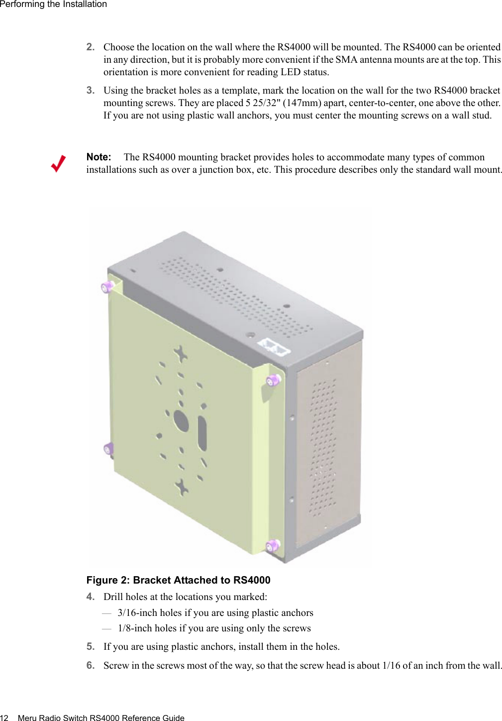
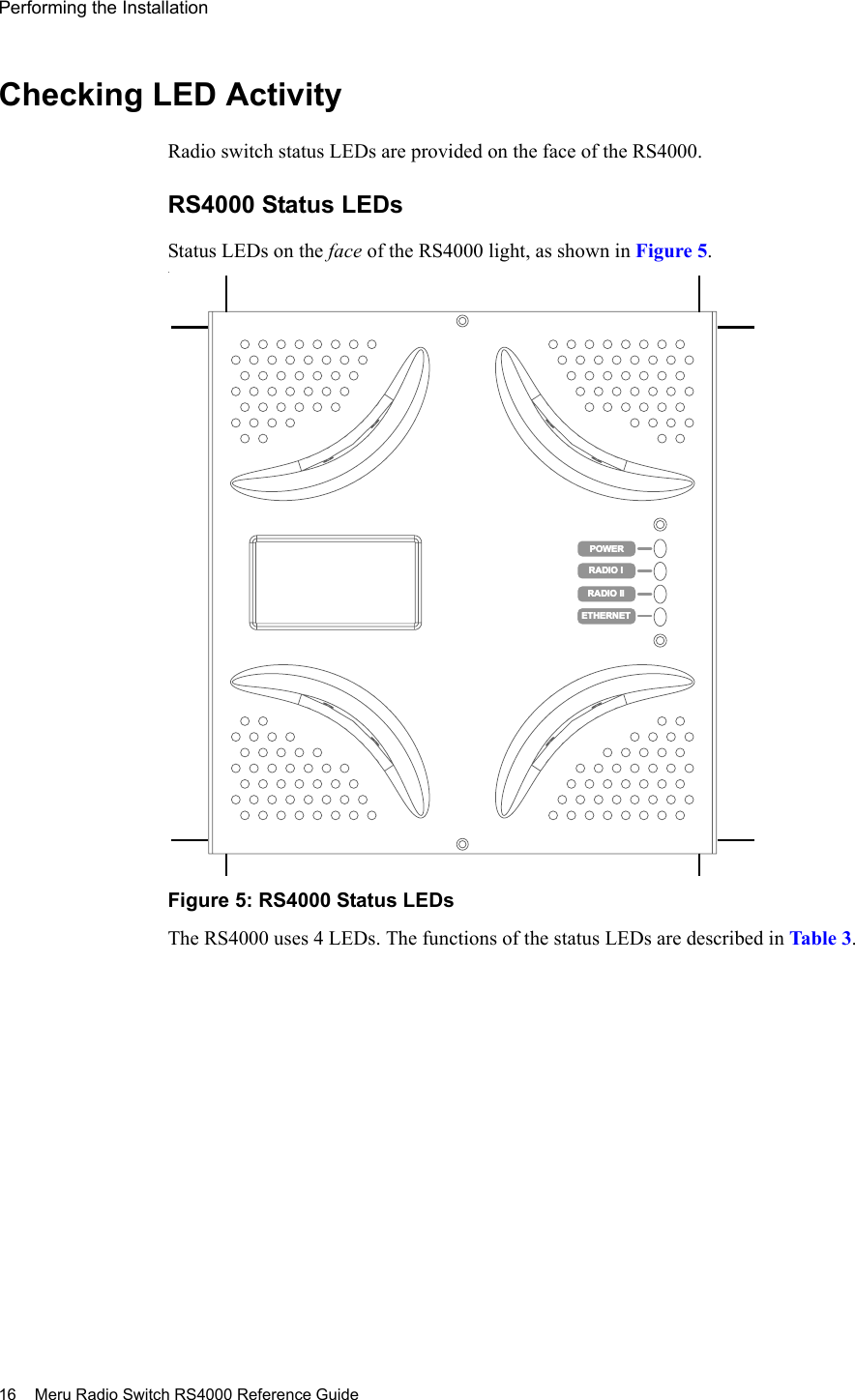
![Performing the Installation Installing the RS4000 11 Activating and Saving ChangesAfter making your configuration changes, it is necessary to activate them using the command activate-conf. Changes are then propagated and started on all radios and will continue running until the system is rebooted.To make sure changes are retained after a system reboot, you must save the active (running) configuration to a startup configuration file, using the command save-conf.Checking the Network ConfigurationBefore exiting network configuration session, check that the settings are correct and to your satisfaction:# show ip [ip] Boot Protocol : Static IP Address : 10.0.221.14 Network Mask : 255.0.0.0 Default Gateway : 10.0.0.20 Domain : merunetworks.com DNS1 : 10.0.0.10 DNS2 : 10.0.0.40 DNS3 : 65.182.161.201 DNS4 : 206.13.28.12If you configured DHCP, you have to use a third-party application to see the address that has been assigned to the RS4000.Exiting the Initial ConfigurationOnce you have confirmed the correct IP address, exit the RS4000 CLI by typing quit at the prompt. Disconnect the RS4000 and proceed to the physical installation instructions. Depending on the type of installation you will be performing, use the procedure:zWall Mounting the RS4000zHoffman Enclosure RS4000 InstallationWall Mounting the RS4000Note:The RS4000 has a security cable slot so you can secure the RS4000 with a standard security cable, such as those used to secure laptop computers (for example, Kensington cable locks).To wall mount an RS4000:1. Remove the bracket from back side the RS4000 if it is attached by unscrewing each of the 4 knurled thumbscrews (see Figure 2).](https://usermanual.wiki/Meru-Networks/RS4000/User-Guide-614624-Page-25.png)
![Configuring of the Radio Switch with the CLI Commands Configuring the Meru RS4000 21 # set snmpcommunity RWManagerIpAddress 192.168.300.100To allow all SNMP managers in the network to have read/write access, do not use the command set snmpcommunity ROManagerIpAddress. Instead, the default IP address setting 0.0.0.0 is used to allow all SNMP managers with the community string CatsCradle to get/set MIB objects.Configuring of the Radio Switch with the CLI CommandsThis section describes additional commands to configure the RS4000, as shown in following sections:zConfiguring the WLAN ParameterszConfiguring an ESSIDzConfiguring System SecurityzConfiguring Radio ParametersConfiguring the WLAN ParametersThe set wif command performs the configuration of the wireless and security properties for the interface. An interface must be specified in each of the commands and the radio interface determines the 802.11 operating mode and some associated features. For example, radio1-1 and radio1-2 operate in mode 802.11a and radio2-1 and radio2-2 operate in either 802.11bg or b mode.To see the default settings, use the show factoryconfig command. .meru_ap# show factoryconfig [system_config]host_name=meru_apsyslog_server=[network_config]boot_proto = staticip_addr = 192.168.1.1mask = 255.255.255.0def_gateway=domain=dns1=dns2=dns3=dns4=Note:If need be, the default IP address can be reset by using the 0.0.0.0 address as argument to the IP address command (snmpcommunity RWManagerIpAddress).](https://usermanual.wiki/Meru-Networks/RS4000/User-Guide-614624-Page-35.png)
![22 Meru Radio Switch RS4000 Reference GuideConfiguring of the Radio Switch with the CLI Commands [radio1-1]status = upessid = meru1-1mode = 11achannel = 36rate = autotx_power = 30rts_threshold = 2312dtim_period = 1publish_ssid = enablebeacon_interval = 100vlan_tag = 0[radio2-1]status = upessid = meru2-1mode = 11gchannel = 1rate = autotx_power = 30rts_threshold = 2312short_preamble = enabledtim_period = 1publish_ssid = enablebeacon_interval = 100vlan_tag = 0[radio1-2]status = upessid = meru1-2mode = 11achannel = 149rate = autotx_power = 30rts_threshold = 2312dtim_period = 1publish_ssid = enablebeacon_interval = 100vlan_tag = 0[radio2-2]status = upessid = meru2-2mode = 11gchannel = 11rate = autotx_power = 30rts_threshold = 2312short_preamble = enabledtim_period = 1publish_ssid = enablebeacon_interval = 100vlan_tag = 0[wifsec_radio1-1]](https://usermanual.wiki/Meru-Networks/RS4000/User-Guide-614624-Page-36.png)
![Configuring of the Radio Switch with the CLI Commands Configuring the Meru RS4000 23 security_mode = nonewep_security_mode = sharedwep_key_len = wep64tx_key_idx = 1rekey_period = 300reauth_period = 3600[wifsec_radio2-1]security_mode = nonewep_security_mode = sharedwep_key_len = wep64tx_key_idx = 1rekey_period = 300reauth_period = 3600[wifsec_radio1-2]security_mode = nonewep_security_mode = sharedwep_key_len = wep64tx_key_idx = 1rekey_period = 300reauth_period = 3600[wifsec_radio2-2]security_mode = nonewep_security_mode = sharedwep_key_len = wep64tx_key_idx = 1rekey_period = 300reauth_period = 3600[radius]primary_server_ip = 10.0.0.1primary_server_port = 1812secondary_server_ip = 10.0.0.2secondary_server_port = 1812[load_balancing]action = startinterval = 1000mode = strict[snmp_agent]sysContact = RSswitchApAgentsysName = meru_apsysLocation = meru_apread_com_str = publicread_mgr_ip = 0.0.0.0read_com_access = readwrite_com_str = test2write_mgr_ip = 0.0.0.0write_com_access = writetrap_com_str = test2trap_mgr_ip = 10.0.0.21uname = admin](https://usermanual.wiki/Meru-Networks/RS4000/User-Guide-614624-Page-37.png)
![Monitoring the RS4000 Managing and Monitoring the RS4000 29 [system] Description : Access Point Up Time(hh:mm:ss.ff) : 04:30:23.41 Contact : RSswitchApAgent Name : meru_ap Location : meru_ap Serial Number : 00:10:C6:AA:11:13 AP Type : RS4000 Boot Version : 1.0 Software Version : 1.1-131 Host Name : meru_ap Syslog Server : 0.0.0.0# show wif [radio1-1] ESSID : cwon-testap Operational Mode : 11a Rate : auto Channel : 36 Short Preamble : disable Tx Power : 30 ESS Vlan Tag : 0 DTIM Period : 1 Publish ESSID : enable Beacon Interval : 100 Rekey Period : 300 Re-authentication Period : 3600 Key Length : wep128 Security Mode : WEP Transmission Key Index : 1 Wep Security Mode : shared WEP Key1 : ************** WEP Key2 : ************** WEP Key3 : ************** WEP Key4 : **************(and so on, for each radio interface)Checking Syslog MessagesSyslog messages are generated and sent to the log file on the syslog server that is configured with the set system syslog_server IP_address command. These message are sent when critical events occur in the WLAN. A sample syslog message follows:03072005_RS_SYSLOG_10](https://usermanual.wiki/Meru-Networks/RS4000/User-Guide-614624-Page-43.png)
![30 Meru Radio Switch RS4000 Reference GuideMonitoring the RS4000 The list of syslog messages are as follows:Checking Security OptionsCheck the settings for the security options using the show wif and show radius commands. Check the example output of the show wif command above. Included are the Security Mode settings (WEP or 802.1X), and the various details that are determined by the mode selected. For example, the WEP Keys, Key Index position, and so forth.If 802.1X is selected, the RADIUS settings for the primary and secondary server can be checked with the show radius command:meru_ap# show radius [radius] IP Address Primary RADIUS Server : 10.0.0.1 Port of Primary RADIUS Server : 1812 Shared Secret of Primary RADIUS Server : ********* IP Address Secondary RADIUS Server : 10.0.0.2 Port of Secondary RADIUS Server : 1812 Shared Secret of Secondary RADIUS Server : *********Checking Network SettingsUse the show ip command to check the network settings:# show ip Network Configuration:03072005_RS_SYSLOG_10 Radio Switch has successfully booted. This message contains the IP address and MAC address of the Radio Switch and also Identifies the device type as RS4000.03072005_RS_SYSLOG_20 FLASH corruption has occurred. The software is then reset to factory defaults.03072005_RS_SYSLOG_30 An upgrade process has been initiated on the RS4000.03072005_RS_SYSLOG_40 An upgrade process has been successfully completed on the RS4000.03072005_RS_SYSLOG_50 An upgrade process has failed on the RS4000. 03072005_RS_SYSLOG_60 The admin user has logged into the RS4000.03072005_RS_SYSLOG_70 The admin user has logged out of the RS4000.03072005_RS_SYSLOG_80 The admin user is unable to log into the RS4000.03072005_RS_SYSLOG_90 The RADIUS server has switched from Primary to Secondary or vice versa. The IP address of the RADIUS Server to which the switch is made is included.](https://usermanual.wiki/Meru-Networks/RS4000/User-Guide-614624-Page-44.png)
![Monitoring the RS4000 Managing and Monitoring the RS4000 31 ----------------------Boot Protocol : dhcpIP Address : 172.16.0.74Network Mask : 255.255.0.0Default Gateway : 172.16.0.1Domain : merunetworks.comDNS1 :DNS2 :DNS3 :DNS4 :Checking whether you have connectivity with the network can be checked with the ping command, once you see the IP address of the RS4000:ping 172.16.0.74Checking Wireless StatisticsTo check the wireless statistics for the entire Radio Switch, use the show dot11counters command (see the command reference page, “show dot11counters” on page 69 for descriptions of the various statistics).You can also check statistics for a particular interface by specifying that interface (radio1-1, for example), as shown in the following example:# show dot11counters radio1-1[radio1-1] Transmitted Fragment Count : 0 Multicast Transmitted Frame Count : 0 Failed Count : 26688 Retry Count : 296975 Multiple Retry Count : 0 Frame Duplicate Count : 217 RTS Success Count : 0 RTS Failure Count : 0 ACK Failure Count : 0 Received Fragment Count : 0 Multicast Received Frame Count : 0 FCS Error Count : 2861434 Transmitted Frame Count : 433603 WEP Undecryptable Count : 0](https://usermanual.wiki/Meru-Networks/RS4000/User-Guide-614624-Page-45.png)
![34 Meru Radio Switch RS4000 Reference Guide ?Displays help for the CLI.Syntax ?Usage Use the ? to display online help for all commands or for a single command to show the available keywords and parameters. The ? can be used at any point on the command line to receive help at that point. Examples Use the following command to display all available commands: # ? help -> Display this message show -> Display system state and configuration information set -> Issue a single configuration command format -> Set output display format to CLI Table, CLI Pretty or CLI Plain history -> Display list of previous commands setenv -> Set CLI session environment variables quit -> Exit the CLI upgrade -> Upgrade system image upldconf -> Upload system configuration dldconf -> Download system configuration save-conf -> Save Running(Active) configuration in flash activate-conf -> Activate(Apply) unsaved configuration reset-to-default -> Reset system configuration to factory default reboot -> Reboot system passwd -> Changes passwordUse the TAB key for unique command completion, the ? key for help,the up/down arrow keys to cycle through previous commands, andCtrl-U to kill the current line.Use the following command to display help for the set system command:#set system ?system [Contact <value>] [Name <value>] [Location <value>] [hostname <value>] [syslog_server <value>] Related Commandshelp](https://usermanual.wiki/Meru-Networks/RS4000/User-Guide-614624-Page-48.png)
![38 Meru Radio Switch RS4000 Reference Guide formatFormats the output of the show command.Syntax format {clipretty | cliplain | clitable}Usage Use this command to format the output of the show command. Each of the keywords formats the output differently and are used to accommodate how the output is used.Typically, the clitable keyword is used for the standard table view of output information. The keywords cliplain and clipretty may be used if the output will be used as input to another process.Examples The following shows how the same output is presented using the three keywords:meru-ap# format clitablemeru_ap# show wif [radio1-1] ESSID : cwon-testap Operational Mode : 11a Rate : auto Channel : 36 Short Preamble : disable Tx Power : 30 ESS Vlan Tag : 0 DTIM Period : 1 Publish ESSID : disable Beacon Interval : 100 Rekey Period : 300 Re-authentication Period : 3600 Key Length : wep128 Security Mode : WEP Transmission Key Index : 1 Wep Security Mode : shared WEP Key1 : ************** WEP Key2 : ************** WEP Key3 : ************** WEP Key4 : **************clipretty Formats output with some amount of white space separation. cliplain Formats output with very little white space separation. clitable Formats output with white space separation that facilitates readability.](https://usermanual.wiki/Meru-Networks/RS4000/User-Guide-614624-Page-52.png)
![Command Reference 39 meru_ap# format cliprettymeru_ap# show wifwif { row[3] { essid "cwon-testap" mode 11a rate auto channel 36 short_preamble disable tx_power 30 ess_vlantag 0 dtim_period 1 publish_essid disable beacon_interval 100 rekey_period 300 reauth_period 3600 key_len wep128 security_mode WEP key_index 1 wep_auth_mode shared key1 "**************" key2 "**************" key3 "**************" key4 "**************" }meru_ap# format cliplainmeru_ap# show wifwif 3 essid "cwon-testap"wif 3 mode 11awif 3 rate autowif 3 channel 36wif 3 short_preamble disablewif 3 tx_power 30wif 3 ess_vlantag 0wif 3 dtim_period 1wif 3 publish_essid disablewif 3 beacon_interval 100wif 3 rekey_period 300wif 3 reauth_period 3600wif 3 key_len wep128wif 3 security_mode WEPwif 3 key_index 1wif 3 wep_auth_mode sharedwif 3 key1 "**************"wif 3 key2 "**************"wif 3 key3 "**************"wif 3 key4 "**************"](https://usermanual.wiki/Meru-Networks/RS4000/User-Guide-614624-Page-53.png)
![Command Reference 49 set ipSets network configuration settings.Syntax set ip boot_protocol {dhcp | static addr IP_address netmask subnet_address} set ip gateway IP_addressset ip domain domain_nameset ip dns[1-4] IP_addressUsage The set ip commands set basic networking parameters that the Radio Switch uses to connect to the network. First enter the command set ip boot_protocol static addr IP_address netmask subnet_address or set ip dhcp to establish how the Radio Switch receives its IP address after booting up. By default, the RS4000 is configured with the IP address/netmask 192.168.1.1/255.255.255.0. With the setting dhcp, the switch automatically receives its IP address and associated network mask settings, as well as the gateway IP address from the DHCP server. If the static keyword is used , the additional keywords and values for addr and netmask must be given, as well as the set ip gateway command. The set ip domain command sets the domain name for the network. The set ip dns1through set ip dns4 commands allow setting up to 4 Domain Name Server IP addresses, where dns1 is the primary server, dns2 is the secondary server, and so forth. dhcp Specifies that the Radio Switch boots with DHCP. The default setting is static addressing. static addr IP_address netmask subnet_addressSpecifies that the Radio Switch boots with the static IP address specified by IP_address and the netmask specified by subnet_address . By default, the IP address is set to 192.168.1.1 and the netmask is set to 255.255.255.0.gateway IP_address Specifies the gateway IP address that the Radio Switch uses.domain domain_name Specifies the domain name of the domain where the Radio Switch resides. The domain name can be a maximum of 32 characters.dns1 IP_addressdns2 IP_addressdns3 IP_addressdns4 IP_addressSpecifies up to four different DNS IP addresses.](https://usermanual.wiki/Meru-Networks/RS4000/User-Guide-614624-Page-63.png)

![Command Reference 61 set wif Configures wireless interface settings.Syntax set wif if essid essid_nameset wif if mode {11a | 11g}set wif if rate {1 | 2 | 5.5 | 6 | 9 | 11 | 12 | 18 | 24 | 36 | 48 | 54 | auto}set wif if channel {1-11 | 36 | 40 | 44 | 48 | 52 | 56 | 60 | 64 | 149 | 153 | 157 | 161 | 165}set wif if short_preamble {enable | disable}set wif if tx_power 1-30set wif if ess_vlantag 0-4094set wif if dtim_period 0-255set wif if publish_essid {enable | disable}set wif if beacon_interval 0-65535set wif if security_mode {none | 8021x | wep}set wif if reauth_period 0-65535set wif if rekey_period 0-65535set wif if key_len {wep64 | wep128}set wif if key_index {1 | 2 | 3 | 4 }set wif if wep_auth_mode {shared | open}set wif if key[1-4] key if Specifies the radio interface (if) to configure (radio1-1 | radio2-1| radio1-2 | radio2-2).Two interfaces (radio1-1 and radio1-2) operate in mode 802.11a and two interfaces (radio2-1 and radio2-2) operate in either 802.11bg, or b mode.The interface designation is a mandatory parameter in all wireless interface commands and is shown as if in the related command syntaxes.essid essid_name Specifies the ESSID (Extended Service Set Identifier) name associated with the radio interface. By default, ESSID meru1-1 is specified for radio1-1 and meru1-2 for radio1-2; ESSID meru2-1 is specified for radio2-1 and meru2-2 for radio2-2. The essid_name must be a maximum of 32 characters and must not contain special characters or spaces. An ESSID must not mix modes (see below) or load balancing cannot be performed.](https://usermanual.wiki/Meru-Networks/RS4000/User-Guide-614624-Page-75.png)
![Command Reference 63 dtim_period 0-255 Specifies the number of beacon intervals that elapse before broadcast frames are sent. Value must be between 0 and 255. Setting the DTIM period to a higher value decreases the frequency of broadcasts sent by the RS4000. If power save is enabled on clients that are connected to the RS4000, clients “wake up” less if fewer broadcasts are sent, which conserves battery life for the clients. The default beacon DTIM period is 1.publish_essid {enable | disable} Specifies whether the RS4000 broadcasts the ESSID (enabled) or not (disabled). By default, an ESSID is broadcast. When an ESSID is broadcast, it is included in the beacon that gets advertised. Clients using passive scanning listen for beacons transmitted by access points. If broadcasting an ESSID is disabled, clients listening for beacons cannot receive ESSID information.beacon_interval {25-500} Specifies the interval in milliseconds between beacon broadcasts. Setting the beacon interval to a higher value decreases the frequency of unicasts and broadcasts sent by the RS4000. If the power-save feature is enabled on clients that are connected to the RS4000, clients “wake up” less if fewer unicasts and broadcasts are sent, which conserves the battery life for the clients. The default interval is 100.security_mode {none | 8021x | wep}Specifies the mode that will be used to enforce WLAN security. The default setting is none.If 8021x is selected, the 802.1X protocol is used and the set radius command must also be invoked to set the RADIUS server configuration parameters. If wep is selected, the following commands must also be used to set the WEP parameters:zset wif if key_lenzset wif if key_indexzset wif if wep_auth_modezset wif if key[1-4]reauth_period 0, 3600-65535 Period in seconds after which 802.1X authenticated wireless clients will be reauthenticated. By default, the period is set to 3600 seconds. A value of 0 means reauthentication is disabled.](https://usermanual.wiki/Meru-Networks/RS4000/User-Guide-614624-Page-77.png)
![Command Reference 67 show assocStationsDisplays the associated stations.Syntax show assocStationsUsage This command lists the number of stations that are associated to the RS4000.Examples The following command shows the number of associated stations:meru_ap# show assocStations [radio1-1] MAC Address : 00:40:96:A9:B0:8D Received bytes : 1481074 Transmitted bytes : 1402598 RSSI : 21](https://usermanual.wiki/Meru-Networks/RS4000/User-Guide-614624-Page-81.png)
![68 Meru Radio Switch RS4000 Reference Guide show configsnmpDisplays the SNMP trap collection status.Syntax show configsnmpUsage Displays whether SNMP trap collection is enabled for the radio interface. Enabling or disabling SNMP trap collection is performed with the command set configsnmp. Configuring trap community is performed with the set trapcommunity command.Examples The following command shows the SNMP status is enabled:meru_ap# show configsnmp [configsnmp] Snmp Trap : enabled(1)Related Commandsset configsnmpset trapcommunity](https://usermanual.wiki/Meru-Networks/RS4000/User-Guide-614624-Page-82.png)
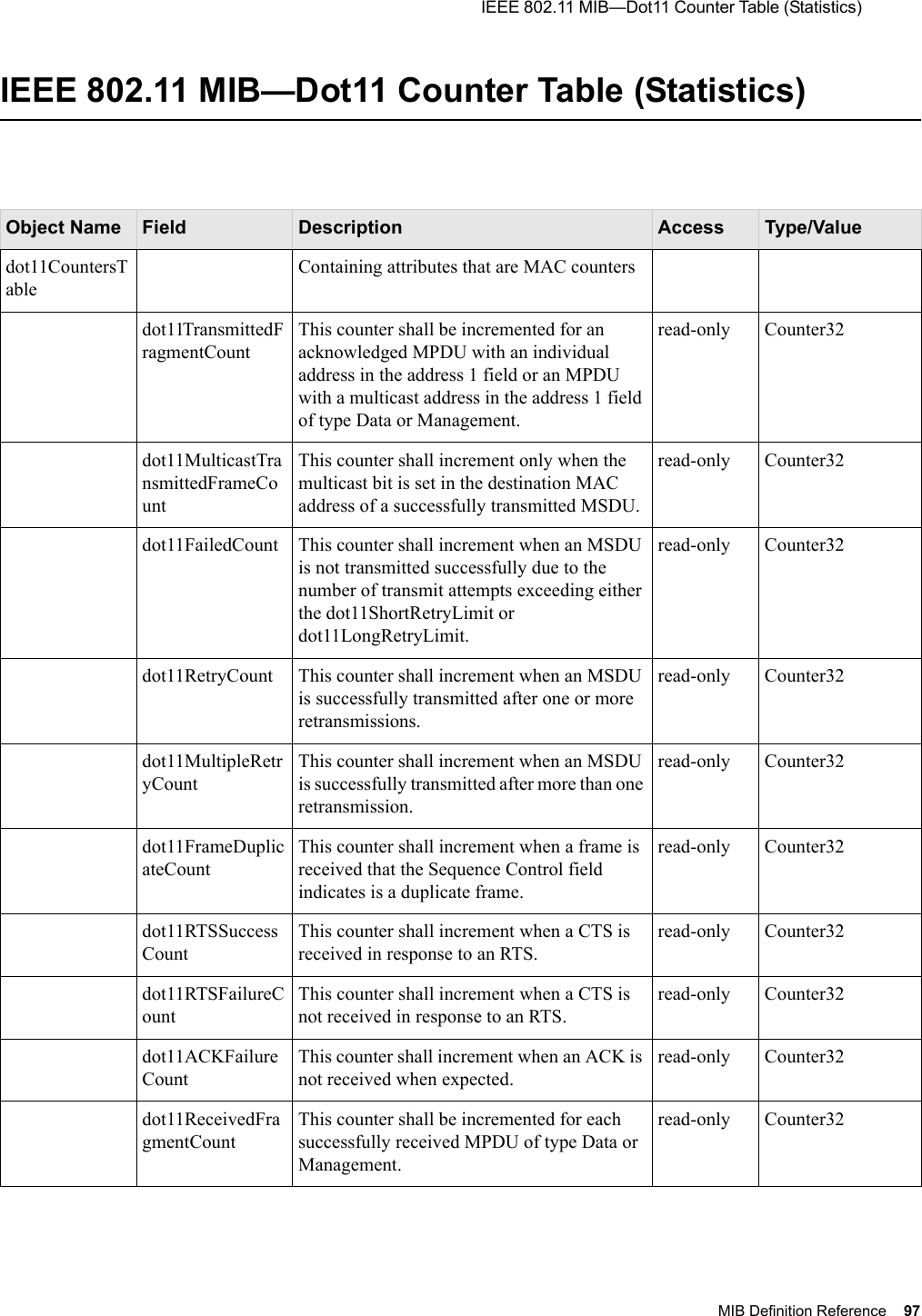
![Command Reference 69 show dot11countersDisplays Dot11counter statistics.Syntax show dot11counters [if] Usage Displays the Dot11radio counter statistics for all wireless interfaces, or with optional argument, displays statistics for specified interface. Examples The following shows the wireless interface configuration for radio1-1:#show dot11counters radio1-1 [radio1-1]if Optional. Specifies the radio interface to show (radio1-1 | radio2-1| radio1-2 | radio2-2).Table 4: Field Descriptions for show dot11coutersStatistic Description[Interface Index] Unique identification number of the wireless interface.Failed Count Total number of failed transmissions.Retry Count Total number of frames that are retransmitted at least once.Frame Duplicate CountTotal number of frames received more than once.RTS Success Count Total number of RTS frames that are successfully transmitted.Received Fragment CountTotal number of frames received that has the fragment bit set.FCS Error Count Total number of packets received which failed Frame Check Sequence validation due to packet corruption.Transmit Frame Count Total number of whole frames transmitted, including unicast, broadcast, and multicast frames.WEP Undecryptable Count Total number of frames received with undecryptable WEP keys ACKs were not received.](https://usermanual.wiki/Meru-Networks/RS4000/User-Guide-614624-Page-83.png)
![Command Reference 71 show factoryconfigDisplays the factory-set configuration.Syntax show factoryconfigUsage Shows factory-set configuration settings. This command shows the initial settings of all configuration parameters, and may be helpful to refer to if some user-initiated configuration changes are not working and you would like to selectively revert to the default settings.Examples The following shows an except of the factory-set configuration file output:meru_ap# show factoryconfig [system_config]host_name=meru_apsyslog_server=[network_config]boot_proto = staticip_addr = 192.168.1.1mask = 255.255.255.0def_gateway=domain=dns1=dns2=dns3=dns4=[radio1-1]Related Commandsshow runningconfig](https://usermanual.wiki/Meru-Networks/RS4000/User-Guide-614624-Page-85.png)
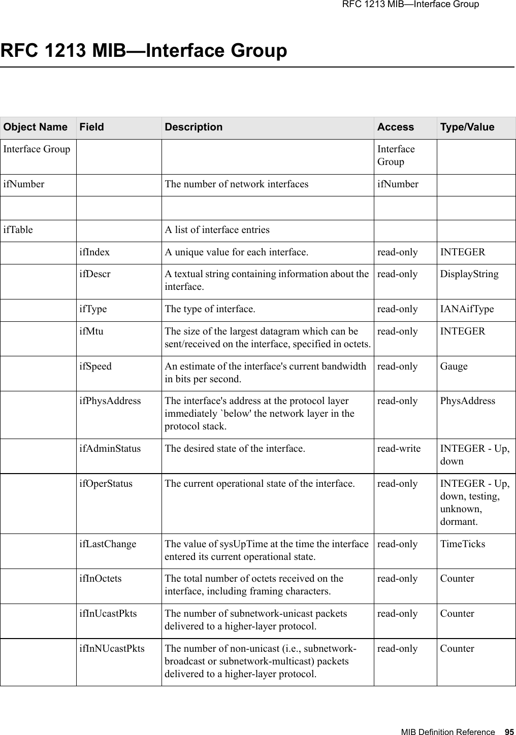
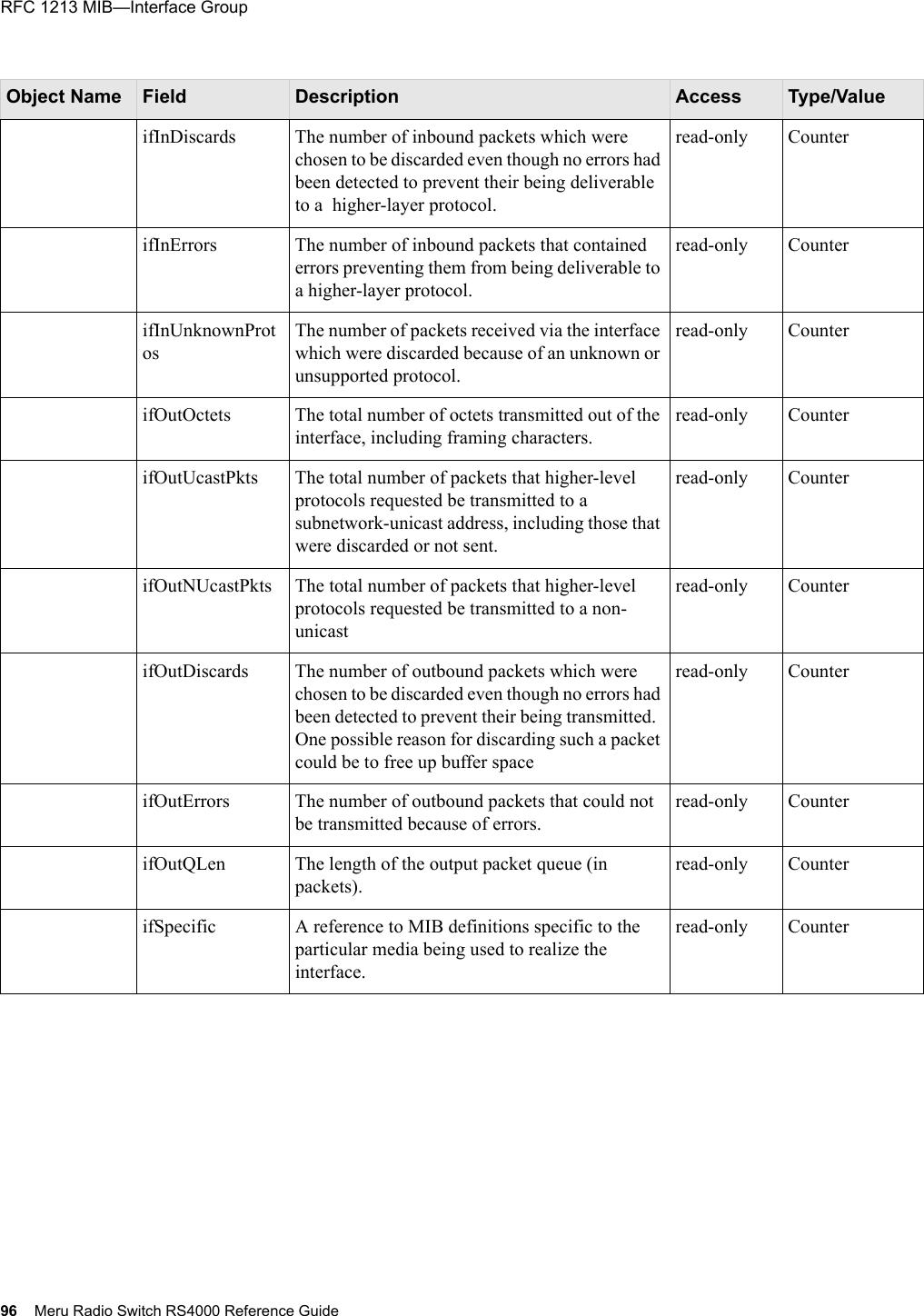
![Command Reference 73 show interfaces Displays the current network interface settings.Syntax show interfaces if Usage Use this command to see the Ethernet (eth1 and eth2) and RF interfaces (radio1-1, radio2-1, radio1-2, and radio2-2) for the RS4000. Alternately, an interface can be specified by a number (for example, 3 for radio1-1) if Optional. Specifies the interface to show (eth1| eth2 | radio1-1 | radio2-1| radio1-2 | radio2-2) or 1, 2, 3, 4, 5, 6, respectively).Table 5: Field Descriptions for show interfacesParameter Description[Interface Name] The name of the interface, for example, eth1, radio1-1.Index The index for identifying this interface.Description Shows a description of the interface.Type Type descriptor.Mtu The Maximum Transmission Unit (MTU) for the interface.Speed (Mbits/sec) The configured speed for the interface.PhysAddress The MAC address of the interface.AdminStatus Indicates whether the wireless interface has been enabled (Up) or taken out of service (Down). OperStatus Indicates whether the interface is operational (up) or unavailable (down) Last Change The date the interface was changed last.InOctets The number of octets received by this interface.InUCastPkts The number of unicast packets received by this interface.InNUCastPkts The number of non-unicast packets received by this interface.](https://usermanual.wiki/Meru-Networks/RS4000/User-Guide-614624-Page-87.png)
![74 Meru Radio Switch RS4000 Reference Guide Examples Use the following command to display the network interface settings:# show interfaces [eth1] Index : 1 Descr : eth1 Type : 802.3 Ethernet Mtu : 1500 Speed : 100 Mbps PhysAddress : 00:10:C6:AA:11:13 AdminStatus : up(1) OperStatus : up(1) LastChange : 00:00:00.00 InOctets : 44426679 InUcastPkts : 44426679 InNUcastPkts : 0 InDiscards : 0 InErrors : 2 InUnknownProtos : 0 OutOctets : 0 OutUcastPkts : 0 OutNUcastPkts : 0 OutDiscards : 0 OutErrors : 0 OutQLen : 0 Specific : 0.0 [eth2] Index : 2 Descr : eth2InDiscards The number of incoming packets discarded by this interface.InErrors The number of incoming packets with errors on this interface.InUnknown Protos The number of packets with an unknown protocol received by this interface.OutOctets The number of octets sent by this interface.OutUcastPkts The number of unicast packets sent by this interface.OutNUcast Pkts The number of non-unicast packets sent by this interface.OutDiscards The number of outgoing packets discarded by this interface.OutErrors The number of outgoing packets with errors on this interface.OutQLen The number of packets in the outgoing packet queue.Table 5: Field Descriptions for show interfacesParameter Description](https://usermanual.wiki/Meru-Networks/RS4000/User-Guide-614624-Page-88.png)
![Command Reference 75 Type : 802.3 Ethernet Mtu : 1500 Speed : 100 Mbps PhysAddress : 00:10:C6:E0:5F:AB AdminStatus : up(1) OperStatus : up(1) LastChange : 00:00:00.00 InOctets : 124770237 InUcastPkts : 124770237 InNUcastPkts : 0 InDiscards : 0 InErrors : 2 InUnknownProtos : 0 OutOctets : 0 OutUcastPkts : 0 OutNUcastPkts : 0 OutDiscards : 0 OutErrors : 0 OutQLen : 0 Specific : 0.0 [radio1-1] Index : 3 Descr : radio1-1 Type : 802.11 Wireless Mtu : 2290 Speed : up to 54 Mbps PhysAddress : 00:10:C6:AA:11:11 AdminStatus : up(1) OperStatus : up(1) LastChange : 00:00:00.00 InOctets : 35377531 InUcastPkts : 35377531 InNUcastPkts : 0 InDiscards : 0 InErrors : 1762 InUnknownProtos : 0 OutOctets : 35148684 OutUcastPkts : 0 OutNUcastPkts : 0 OutDiscards : 0 OutErrors : 14 OutQLen : 0 Specific : 0.0 [radio1-2] Index : 4 Descr : radio1-2 Type : 802.11 Wireless Mtu : 2290 Speed : up to 54 Mbps PhysAddress : 00:10:C6:1D:12:88 AdminStatus : up(1) OperStatus : up(1) LastChange : 00:00:00.00](https://usermanual.wiki/Meru-Networks/RS4000/User-Guide-614624-Page-89.png)
![76 Meru Radio Switch RS4000 Reference Guide InOctets : 1820 InUcastPkts : 1820 InNUcastPkts : 0 InDiscards : 0 InErrors : 21057 InUnknownProtos : 0 OutOctets : 32772009 OutUcastPkts : 0 OutNUcastPkts : 0 OutDiscards : 0 OutErrors : 707 OutQLen : 0 Specific : 0.0 [radio2-1] Index : 5 Descr : radio2-1 Type : 802.11 Wireless Mtu : 2290 Speed : up to 54 Mbps PhysAddress : 00:10:C6:AA:11:12 AdminStatus : up(1) OperStatus : up(1) LastChange : 00:00:00.00 InOctets : 0 InUcastPkts : 0 InNUcastPkts : 0 InDiscards : 0 InErrors : 229402 InUnknownProtos : 0 OutOctets : 3234900 OutUcastPkts : 0 OutNUcastPkts : 0 OutDiscards : 0 OutErrors : 1340 OutQLen : 0 Specific : 0.0 [radio2-2] Index : 6 Descr : radio2-2 Type : 802.11 Wireless Mtu : 2290 Speed : up to 54 Mbps PhysAddress : 00:10:C6:1D:12:89 AdminStatus : up(1) OperStatus : up(1) LastChange : 00:00:00.00 InOctets : 0 InUcastPkts : 0 InNUcastPkts : 0 InDiscards : 0 InErrors : 936447 InUnknownProtos : 0 OutOctets : 32724557](https://usermanual.wiki/Meru-Networks/RS4000/User-Guide-614624-Page-90.png)
![78 Meru Radio Switch RS4000 Reference Guide show ip Displays the current network configuration settings.Syntax show ipUsage Use this command to see the stored RS4000 IP settings. The IP settings are set with the command set ip.Examples Use the following command to display the network addresses settings:# show ip [ip] Boot Protocol : DHCP IP Address : 10.0.221.14 Network Mask : 255.0.0.0 Default Gateway : 10.0.0.20 Domain : merunetworks.com DNS1 : 10.0.0.10 DNS2 : 10.0.0.40 DNS3 : 65.182.161.201 DNS4 : 206.13.28.12Table 6: Field Descriptions for show ipParameter DescriptionBoot Protocol The boot protocol that determines whether the Radio Switch boots with a static IP address or one assigned using DHCP. IP Address The IP address for the RS4000. By default, the IP address is set to 192.168.1.1.Network Mask The subnet mask for the RS4000 IP address. By default, the netmask is set to 255.255.0.0Default Gateway The gateway IP address that the RS4000 uses.Domain The domain name of the domain where the Radio Switch resides.DNS1-DNS4 The addresses for up to four different DNS IP addresses.](https://usermanual.wiki/Meru-Networks/RS4000/User-Guide-614624-Page-92.png)
![Command Reference 81 show loadbalanceDisplays the configuration for the Load Balancer.Syntax show loadbalance Usage Use this command to display the stored settings for the load balancer feature. Load balancer settings that display with this command are set with the set loadbalance command.Examples Use the following command to display stored settings for the load balancer feature.meru_ap# show loadbalance [loadbalance] Action : start Interval : 1000 Operational Mode : strictRelated Commandsset loadbalance](https://usermanual.wiki/Meru-Networks/RS4000/User-Guide-614624-Page-95.png)
![82 Meru Radio Switch RS4000 Reference Guide show radius Displays running configuration for RADIUS server.Syntax show radius Usage Use this command to display the stored RADIUS server settings. Settings that display with this command are set with the command set radius.Examples Use the following command to display the RADIUS server settings:# show radius [radius] IP Address Primary RADIUS Server : 10.0.0.1 Port of Primary RADIUS Server : 1812 Shared Secret of Primary RADIUS Server : ********* IP Address Secondary RADIUS Server : 10.0.0.2 Port of Secondary RADIUS Server : 1812 Shared Secret of Secondary RADIUS Server : *********Related Commandsset radiusset wif](https://usermanual.wiki/Meru-Networks/RS4000/User-Guide-614624-Page-96.png)
![Command Reference 83 show runningconfigShow configuration of running system.Syntax show runningconfigUsage The configuration shown by this command is stored in "running nms.conf" file and NOT the actual running configuration of each components. For this configuration to take effect, the user must use the command save-conf.Examples The following shows an except of the running configuration:meru_ap# show runningconfig [system_config]host_name=meru_apsyslog_server=[network_config]boot_proto = dhcp[radio1-1]status = upessid = cwon-testapmode = 11achannel = 36rate = autotx_power = 30rts_threshold = 2312dtim_period = 1publish_ssid = enablebeacon_interval = 100vlan_tag = 0[radio2-1]status = upessid = cwon-testap2-1mode = 11bchannel = 3rate = autotx_power = 30----More----Related Commandssave-conf](https://usermanual.wiki/Meru-Networks/RS4000/User-Guide-614624-Page-97.png)
![84 Meru Radio Switch RS4000 Reference Guide show snmpcommunityDisplays the SNMP community configuration.Syntax show snmpommunityUsage Displays the SNMP community information for the radio interface. The display shows the community string and IP address settings for configured SNMP managers with the ReadOnly and ReadWrite privilege.Configuring an SNMP community string and IP address of the SNMP manager is performed with the set snmpcommunity command. Enabling or disabling SNMP is performed with the command set configsnmp. Configuring trap community and IP address of the SNMP manager that the traps are sent to is performed with the set trapcommunity command.Examples The following command shows the SNMP trap collection information; that is, that test2 is the string used as the password and the traps are being sent to the manager at 10.0.0.21:meru_ap# show snmpcommunity [snmpcommunity] Read Privilege : snmpRo(1) Read Community String : public Read Manager IP Address : 0.0.0.0 Read Write Privilege : snmpRw(2) Read Write Community String : test2 Read Write Manager IP Address : 0.0.0.0Related Commandsset configsnmpset snmpcommunityset trapcommunity](https://usermanual.wiki/Meru-Networks/RS4000/User-Guide-614624-Page-98.png)
![Command Reference 85 show startupconfigShow starting configuration of system.Syntax show startupconfigUsage The configuration shown by this command is stored in nms.conf file on "flash" and is the configuration that is used at system boot. However, if the user has executed CLI commands after system start-up and activated them with the command activate-conf, the executed command configuration can be viewed by the command show runningconfig. If the system is rebooted without saving the running configuration, this configuration (the startupconfig) will again take effect.Examples The following shows an except of the startup configuration file:meru_ap# show startupconfig [system_config]host_name=meru_apsyslog_server=[network_config]boot_proto = dhcp[radio1-1]status = upessid = cwon-testapmode = 11achannel = 36rate = autotx_power = 30rts_threshold = 2312dtim_period = 1publish_ssid = enablebeacon_interval = 100vlan_tag = 0Related Commandsactivate-confrebootsave-conf](https://usermanual.wiki/Meru-Networks/RS4000/User-Guide-614624-Page-99.png)
![86 Meru Radio Switch RS4000 Reference Guide show systemDisplays the stored system settings.Syntax show system Usage Use this command to see the stored RS4000 system settings. Information such as Description, Contact, Name, Location, Host Name, and Syslog Server are entered with the command set system. Other entries such as Serial Number, and AP Type are hardware-specific and cannot be changed. The Up Time, Boot Version, and Software Version are software-specific and cannot be changed.Examples Use the following command to display the system settings:#show system [system] Description : Access Point Up Time(hh:mm:ss.ff) : 00:00:10.74 Contact : meru_ap Name : meru_ap Location : meru_ap Serial Number : 00:10:C6:AA:11:13 AP Type : RS4000 Boot Version : 1.0 Software Version : 1.1-131 Host Name : meru_ap Syslog Server : 0.0.0.0Related Commandsset system](https://usermanual.wiki/Meru-Networks/RS4000/User-Guide-614624-Page-100.png)
![Command Reference 87 show trapcommunityDisplays the SNMP trap community configuration.Syntax show trapcommunityUsage Displays the SNMP trap collection and forwarding information for the radio interface. Configuring an SNMP trap community string and IP address of the SNMP manager to which the traps are sent to is performed with the set trapcommunity command. Enabling or disabling SNMP is performed with the command set configsnmp. Examples The following command shows the SNMP trap collection information; that is, that test2 is the string used as the password and the traps are being sent to the manager at 10.0.0.21:meru_ap# show trapcommunity [trapcommunity] Trap Community String : test2 Trap Community Manager IP Address : 10.0.0.21Related Commandsset configsnmpset trapcommunity](https://usermanual.wiki/Meru-Networks/RS4000/User-Guide-614624-Page-101.png)
![88 Meru Radio Switch RS4000 Reference Guide show unsavedconfigShow unsaved configuration changes.Syntax show unsavedconfigUsage This command lists the commands that have been executed since the last saved version of the configuration. For the commands listed in this command’s output to take effect, the user must use the command save-conf. If there have been no commands executed since the last saved configuration, the output “No Un-saved Configuration!!” is displayed.Examples meru_ap# show unsavedconfig NOTE: Running configuration is displayed inside brackets"()"[snmp_agent] sysContact = merunetworks (meru_ap)Related Commandssave-conf](https://usermanual.wiki/Meru-Networks/RS4000/User-Guide-614624-Page-102.png)
![Command Reference 89 show wifDisplays wireless radio interface configuration.Syntax show wif [if] [object] Usage Displays the current configuration for all wireless interfaces, or with optional arguments, displays configuration for specified interface, or particular statistic (object) for specified interface. The setting that are displayed for this command are set with the set wif command.Examples The following shows the wireless interface configuration for radio1-1:#show wif radio1-1 [radio1-1] ESSID : cwon-testap Operational Mode : 11a Rate : auto Channel : 36 Short Preamble : disable Tx Power : 30 ESS Vlan Tag : 0 DTIM Period : 1 Publish ESSID : disable Beacon Interval : 100 Rekey Period : 300 Re-authentication Period : 3600 Key Length : wep128 Security Mode : WEP Transmission Key Index : 1 Wep Security Mode : shared WEP Key1 : ************** WEP Key2 : ************** WEP Key3 : ************** WEP Key4 : **************To show information for an object, channel, on radio1-1, use the following example command:meru_ap# show wif radio1-1 channel if Optional. Specifies the radio interface to show (radio1-1 | radio2-1| radio1-2 | radio2-2).object Optional. Show specific object information (for example, channel) on the specified interface.](https://usermanual.wiki/Meru-Networks/RS4000/User-Guide-614624-Page-103.png)
![90 Meru Radio Switch RS4000 Reference Guide [radio1-1] Channel : 36Related Commandsset wif](https://usermanual.wiki/Meru-Networks/RS4000/User-Guide-614624-Page-104.png)