Meru Networks RS4000 Wireless Radio Switch, Model RS4000 User Manual RS
Meru Networks Inc. Wireless Radio Switch, Model RS4000 RS
users manual

Meru Radio Switch RS4000
Reference Guide
Copyright © Meru Networks, Inc., 2003–2005. All rights reserved.
Other names and brands may be claimed as the property of others.
Document Number: 882-80000 Rev A
Contents iii
Contents
About This Guide . . . . . . . . . . . . . . . . . . . . . . . . . . . . . . xi
Audience . . . . . . . . . . . . . . . . . . . . . . . . . . . . . . . . xi
In This Guide . . . . . . . . . . . . . . . . . . . . . . . . . . . . . . xi
Other Sources of Information . . . . . . . . . . . . . . . . . . . . . . . . xi
Typographic Conventions . . . . . . . . . . . . . . . . . . . . . . . . . xii
Contacting Meru . . . . . . . . . . . . . . . . . . . . . . . . . . . . . xii
Customer Services and Support . . . . . . . . . . . . . . . . . . . . . . xii
Chapter 1
About the Radio Switch RS4000 . . . . . . . . . . . . . . . . . . . . . . 1
Hardware Features and Specifications . . . . . . . . . . . . . . . . . . . 2
WLAN Features and Specifications . . . . . . . . . . . . . . . . . . . . 4
Management and Monitoring . . . . . . . . . . . . . . . . . . . . . . . 4
Chapter 2
Installing the RS4000 . . . . . . . . . . . . . . . . . . . . . . . . . . . . 5
Planning the Installation . . . . . . . . . . . . . . . . . . . . . . . . . . 5
Prerequisites and System Requirements. . . . . . . . . . . . . . . . . . . 5
Check Product Package Contents . . . . . . . . . . . . . . . . . . . . . 5
Safety Precautions . . . . . . . . . . . . . . . . . . . . . . . . . . . 6
Installation Guidelines . . . . . . . . . . . . . . . . . . . . . . . . . 7
Performing the Installation . . . . . . . . . . . . . . . . . . . . . . . . . 9
Installation Summary . . . . . . . . . . . . . . . . . . . . . . . . . . 9
Initial Configuration of the RS4000 . . . . . . . . . . . . . . . . . . . . 9
Wall Mounting the RS4000 . . . . . . . . . . . . . . . . . . . . . . . 11
Hoffman Enclosure RS4000 Installation . . . . . . . . . . . . . . . . . . 14
Power On Components . . . . . . . . . . . . . . . . . . . . . . . . . 15
Checking LED Activity . . . . . . . . . . . . . . . . . . . . . . . . . 16
Chapter 3
Configuring the Meru RS4000 . . . . . . . . . . . . . . . . . . . . . . 19
Determine How the RS4000 Is To Be Managed . . . . . . . . . . . . . . . . . 19
Using the CLI with a Telnet/SSH Connection . . . . . . . . . . . . . . . . 19
Using SNMP . . . . . . . . . . . . . . . . . . . . . . . . . . . . . 19
Configuring of the Radio Switch with the CLI Commands . . . . . . . . . . . . . 21
Configuring the WLAN Parameters . . . . . . . . . . . . . . . . . . . . 21
Configuring an ESSID . . . . . . . . . . . . . . . . . . . . . . . . . 24
Configuring System Security . . . . . . . . . . . . . . . . . . . . . . . 24
Configuring Radio Parameters . . . . . . . . . . . . . . . . . . . . . . 24
Activating and Saving Changes . . . . . . . . . . . . . . . . . . . . . . . 25
iv Meru Radio Switch RS4000 Reference Guide
Chapter 4
Managing and Monitoring the RS4000 . . . . . . . . . . . . . . . . . 27
Managing the RS4000 . . . . . . . . . . . . . . . . . . . . . . . . . . . 27
Saving the Configuration to a Remote Server . . . . . . . . . . . . . . . . 27
Upgrading the System Software . . . . . . . . . . . . . . . . . . . . . 27
Monitoring the RS4000 . . . . . . . . . . . . . . . . . . . . . . . . . . 28
Checking System Details . . . . . . . . . . . . . . . . . . . . . . . . 28
Checking Syslog Messages . . . . . . . . . . . . . . . . . . . . . . . 29
Checking Security Options . . . . . . . . . . . . . . . . . . . . . . . 30
Checking Network Settings . . . . . . . . . . . . . . . . . . . . . . . 30
Checking Wireless Statistics . . . . . . . . . . . . . . . . . . . . . . . 31
Appendix A
Command Reference . . . . . . . . . . . . . . . . . . . . . . . . . . . 33
Appendix B
MIB Definition Reference . . . . . . . . . . . . . . . . . . . . . . . . 93
RFC 1212 MIB—System Group . . . . . . . . . . . . . . . . . . . . . . . 93
RFC 1213 MIB—Interface Group . . . . . . . . . . . . . . . . . . . . . . 95
IEEE 802.11 MIB—Dot11 Counter Table (Statistics) . . . . . . . . . . . . . . 97
Meru Enterprise MIB—AP System Entry . . . . . . . . . . . . . . . . . . . 98
Meru Enterprise MIB—Network Configuration MIB. . . . . . . . . . . . . . . 99
Meru Enterprise MIB—Load Balancing MIB. . . . . . . . . . . . . . . . . . 100
Meru Enterprise MIB—Global Radius Profile Configuration MIB . . . . . . . . . 100
Meru Enterprise MIB—Meru Interface Table. . . . . . . . . . . . . . . . . . 101
Meru Enterprise MIB—Trap Community Interface . . . . . . . . . . . . . . . 104
Meru Enterprise MIB—SNMP Community Interface . . . . . . . . . . . . . . 104
Meru Enterprise MIB—SNMP Traps Flag . . . . . . . . . . . . . . . . . . . 105
Meru Enterprise MIB—Global Entry. . . . . . . . . . . . . . . . . . . . . 105
Meru Enterprise MIB—Syslog Table . . . . . . . . . . . . . . . . . . . . . 106
Meru Enterprise MIB—File Transfer Table . . . . . . . . . . . . . . . . . . 107
Meru Enterprise MIB—Upgrade Flag. . . . . . . . . . . . . . . . . . . . . 109
Meru Enterprise MIB—Upgrade Status Flag . . . . . . . . . . . . . . . . . . 109
Appendix C
Specifications . . . . . . . . . . . . . . . . . . . . . . . . . . . . . . . 111
FCC Compliance . . . . . . . . . . . . . . . . . . . . . . . . . . . . . 111
Wireless Interface . . . . . . . . . . . . . . . . . . . . . . . . . . . . 112
Ethernet Interface . . . . . . . . . . . . . . . . . . . . . . . . . . . . 112
Physical . . . . . . . . . . . . . . . . . . . . . . . . . . . . . . . . 112
Appendix D
Regulatory Information . . . . . . . . . . . . . . . . . . . . . . . . . 113
Federal Communications Commission (FCC) Declaration of Conformity (DoC)
and Instructions . . . . . . . . . . . . . . . . . . . . . . . . 113
Declaration of Conformity. . . . . . . . . . . . . . . . . . . . . . . . 113
Instructions . . . . . . . . . . . . . . . . . . . . . . . . . . . . . 114
List of Regulatory Compliance Certifications Summary by Country . . . . . . . . . 115
Contents v
Appendix E
Channels . . . . . . . . . . . . . . . . . . . . . . . . . . . . . . . . . . 117
Channels . . . . . . . . . . . . . . . . . . . . . . . . . . . . . . . 117
IEEE 802.11a . . . . . . . . . . . . . . . . . . . . . . . . . . . . 117
IEEE 802.11bg . . . . . . . . . . . . . . . . . . . . . . . . . . . 118
Appendix F
Translated Safety Warnings . . . . . . . . . . . . . . . . . . . . . . . 121
Dipole Antenna Installation Warning . . . . . . . . . . . . . . . . . . . . 122
Explosive Device Proximity Warning . . . . . . . . . . . . . . . . . . . . 123
Installation Warning . . . . . . . . . . . . . . . . . . . . . . . . . . . 124
Circuit Breaker (15A) Warning . . . . . . . . . . . . . . . . . . . . . . 125
vi Meru Radio Switch RS4000 Reference Guide
List of Figures vii
List of Figures
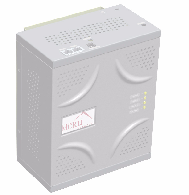
Figure 1 Meru Radio Switch RS4000 .....................................................................................2
Figure 2 Bracket Attached to RS4000 ....................................................................................12
Figure 3 Antenna Mounting Bracket ......................................................................................13
Figure 4 RS4000 Top Panel ....................................................................................................15
Figure 5 RS4000 Status LEDs ................................................................................................16
viii Meru Radio Switch RS4000 Reference Guide
List of Tables ix
List of Tables
Table 1 RS4000 Hardware Features ..................................................................................... 3
Table 2 RS4000 Installation Tools........................................................................................ 8
Table 3 RS4000 LED Descriptions....................................................................................... 17
Table 4 Field Descriptions for show dot11couters ............................................................... 69
Table 5 Field Descriptions for show interfaces .................................................................... 73
Table 6 Field Descriptions for show ip................................................................................. 78
Table 7 802.11abg Wireless Interface Specifications........................................................... 112
Table 8 IEEE 802.11a Channels ........................................................................................... 117
Table 9 IEEE 802.11bg Channels......................................................................................... 119
xMeru Radio Switch RS4000 Reference Guide

About This Guide xi
About This Guide
This guide describes the features, installation, configuration, and maintenance of the Meru Radio
Switch, RS4000.
Audience
This guide is intended for system integrators, installers and network operators who are responsible for
the installation and operation of the the Meru Radio Switch.
In This Guide
This guide includes the following chapters:
zChapter 1, “About the Radio Switch RS4000”
zChapter 2, “Installing the RS4000”
zChapter 3, “Configuring the Meru RS4000”
zChapter 4, “Managing and Monitoring the RS4000”
zAppendix A, “Command Reference”
zAppendix B, “MIB Definition Reference”
zAppendix C, “Specifications”
zAppendix E, “Channels”
zAppendix F, “Translated Safety Warnings”
Other Sources of Information
Additional information about wireless LAN networking is available in the following about external
sources.
zStevens, W. R. 1994. TCP/IP Illustrated, Volume 1, The Protocols. Addison-Wesley, Reading,
Mass.

xii Meru Radio Switch RS4000 Reference Guide
Typographic Conventions
zGast, M.S. 2002. 802.11 Wireless Networks, The Definitive Guide. O’Reilly and Associates,
Sebastopol, Calif.
Typographic Conventions
This document uses the following typographic conventions to help you locate and identify
information:
Contacting Meru
You can visit Meru Networks on the Internet at this URL:
http://www.merunetworks.com
Click the Support menu button to view Meru Customer Services and Support information.
Customer Services and Support
For assistance, contact Meru Customer Services and Support 24 hours a day at 1-888-637-8952
(1-888-Meru-WLA(N)) or 1-408-215-5305. Email can be sent to support@merunetworks.com.
Meru Customer Services and Support provide end users and channel partners with the following:
zTelephone technical support
zSoftware update support
zSpare parts and repair service
RMA Procedures
Contact Meru Customer Services and Support for a Return Material Authorization (RMA) for any
Meru equipment.
Note:
Provides extra information, tips, and hints regarding the topic.
Caution!
Identifies important information about actions that could result in damage to or
loss of data, or could cause the application to behave in unexpected ways.
Warning!
Identifies critical information about actions that could result in equipment failure
or bodily harm.
Contacting Meru
About This Guide xiii
Please have the following available when making a call:
zCompany and contact information
zEquipment model and serial numbers
zMeru software release and revision numbers (for example, 3.0.0-35)
zA description of the symptoms the problem is manifesting
zNetwork configuration
xiv Meru Radio Switch RS4000 Reference Guide
Contacting Meru
About the Radio Switch RS4000 1
Chapter 1
About the Radio Switch RS4000
The Meru Networks Radio Switch RS4000 enables high-capacity enterprise-class wireless LAN
connectivity with full support of standard 802.11 security and network management features. Each
RS4000 contains four built-in 802.11a/bg radios for high data and voice throughput – an essential
requirement for high user-density environments with several simultaneous users. Classrooms and
convention halls are typical deployment applications of the Radio Switch. Deploying the Radio
Switch is easy—just like wireless access points, the Radio Switch can be installed wherever wireless
coverage is needed. For large buildings with multiple rooms and floors, more than one Radio Switch
can be installed to cover the desired area. Wireless users can seamlessly roam from one Radio Switch
to another, getting high-capacity WLAN access throughout the wireless enterprise enabled with
multiple Radio Switches. The RS4000 also balances radio traffic across its RF channels and resolves
contention within each RF channel such that users receive a switched wireless experience with
dedicated bandwidth to execute a variety of applications ranging from web browsing and VoIP
mobility to multimedia streaming.
The RS4000 comes with one high-gain omni-directional indoor antenna that aggregates and layers
radio transmissions from each of the built-in radios. The antenna can broadcast every channel
available to blanket the area around the Radio Switch, yet avoid interference and contention issues.
This simplifies deployment efforts by eliminating the need for additional antennas for each radio.
More importantly, RF channel planning efforts are greatly simplified.
Using the RS4000, wireless users experience the benefits of switching technology, now on Wi-Fi—
dedicated bandwidth, traffic separation, and the ability to run multi-service networks.
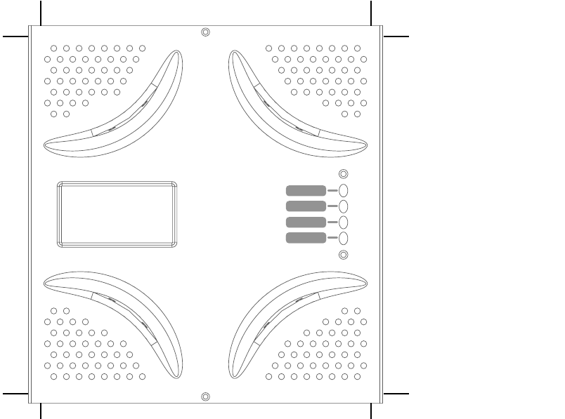
2Meru Radio Switch RS4000 Reference Guide
Figure 1: Meru Radio Switch RS4000
Hardware Features and Specifications
Meru’s Radio Switch, RS4000 contains four 802.11 (two 802.11a and two 802.11bg) radios that can
transmit and receive simultaneously on four different channels to increase the total available wireless
bandwidth at a given area. The RS4000 must be connected to the LAN using one or two 10/100 Mbps
Ethernet connections and can also be powered over Ethernet—using two IEEE 802.3af POE
connections, with 15W power on each connector.

About the Radio Switch RS4000 3
The RS4000 works in conjunction with an external wideband RF combination omni directional
(WRC/OD) antenna. Only one antenna is needed for simultaneous operation of all radios of an
RS4000 in both the 2.4GHz and 5GHz bands. The antenna must be connected to the Radio Switch
using any one of the low-loss antenna cables provided in the antenna packaging.
The RS4000 is a blade-server-type modular design for field-upgrades. By replacing the radio blade
inside the RS4000, a higher number of 802.11a/bg radios and/or 802.11n can be supported.
The following table lists the key hardware features of the RS4000.
Table 1: RS4000 Hardware Features
Feature Description
802.11 Connectivity Two 802.11bg radios (2.4GHz)
Two 802.11a radios (5 GHz)
Ethernet Connectivity Two auto-sensing 10/100 Mbps ports
Power Provided by two 802.3af Power Over Ethernet
connections (11W per connector)
LEDs Power, Radio Activity, and Ethernet Activity
LEDs per radio
Dimensions 9.5" x 8.5" x 3.875"
Mounting Options RS4000 has mounting brackets for:
zCeiling Mount
zWall Mount
zInside NEMA Enclosures (Hoffman, etc)
Antenna Wideband RF Combination/Omni-Directional
(WRC/OD) Antenna. 5dBi gain. Indoor use.
Antenna Cables 3’ low-loss cables (default option)
6’ and plenum-rated cables (available option)
Field-Upgradability Modular radio blade for upgrades
4Meru Radio Switch RS4000 Reference Guide
WLAN Features and Specifications
z802.11a and 802.11b/g client connectivity
zFour ESSIDs and four BSSID support
zL2 Security
—WEP-64 and WEP-128
—802.1X PEAP
—Dynamic load balancing
—VLAN tagging support
Management and Monitoring
Connect to the switch for management and monitoring is provided with the following:
zAllows a maximum of two connections via SSH and Telnet (including two simultaneous SSH
sessions or two Telnet sessions; or one of each ) For SSH sessions, the SecureCRT and SSH
Sessions applications are verified for inter operability.
zConsole over Ethernet support for local administration
zSNMP v1 & v2c support for remote management
zIOS-like Command Line Interface (CLI)
zSyslog for remote logging

Installing the RS4000 5
Chapter 2
Installing the RS4000
This chapter describes how to physically install the Meru RS4000. It contains the following sections:
zPlanning the Installation
zPerforming the Installation
Planning the Installation
Before performing the installation, be sure that you understand and have read the following sections:
zPrerequisites and System Requirements
zCheck Product Package Contents
zSafety Precautions
zInstallation Guidelines
Prerequisites and System Requirements
The following prerequisites and system requirements must be met:
zLayer 2 connection to RS4000 from PC or Laptop for configuring initial network management
settings
z2 IEEE 802.3 PoE connections— one to each Ethernet port, yielding a maximum power
specification of 15W per port
zNetwork switch for connecting all networking components
zTelnet or SSH application
Check Product Package Contents
Confirm that the RS4000 shipping package contains the following items:
zOmni-directional antenna with 2 antenna cables and mounting bracket
zRS4000 with mounting bracket and mounting plate
zCD-ROM containing RS4000 software and documentation

6 Meru Radio Switch RS4000 Reference Guide
Planning the Installation
zRS4000 Release Notes
Safety Precautions
Follow the guidelines in this section to ensure proper operation and safe use of the Radio Switch.
FCC Safety Compliance Statement
The FCC with its action in ET Docket 96-8 has adopted a safety standard for human exposure to radio
frequency (RF) electromagnetic energy emitted by FCC certified equipment. When used with
approved Meru Radio Switch antennas, Meru RS4000 product meets the uncontrolled environmental
limits found in OET-65 and ANSI C95.1, 1991. Proper installation of this radio according to the
instructions found in this manual will result in user exposure that is substantially below the FCC
recommended limits.
General Safety Guidelines
zDo not touch or move antenna(s) while the unit is transmitting or receiving.
zDo not hold any component containing a radio so that the antenna is very close to or touching any
exposed parts of the body, especially the face or eyes, while transmitting.
zThe use of wireless devices in hazardous locations is limited to the constraints posed by the local
codes, the national codes, and the safety directors of such environments.
Warnings
Translated versions of the following safety warnings are provided in Appendix F.
Warning!
In order to comply with FCC radio frequency (RF) exposure limits, dipole antennas
should be located at a minimum of 7.9 inches (20 cm) or more from the body of all persons.
Warning!
Do not operate your wireless network device near unshielded blasting caps or in an
explosive environment unless the device has been modified to be especially qualified for such use.
Warning!
Do not work on the system or connect or disconnect cables during periods of lightning
activity.
Warning!
Read the installation instructions before you connect the system to its power source.
Warning!
This product relies on the building's installation for short-circuit (overcurrent) protection.
Ensure that a fuse or circuit breaker no larger than 120 VAC, 15A U.S. (240 VAC, 10A international)
is used on the phase conductors (all current-carrying conductors).

Planning the Installation
Installing the RS4000 7
Installation Guidelines
The RS4000 requires a location that meets the following:
zA location to mount the antenna within 3’ of the RS4000 and with relatively unobstructed access
to the client stations
zPower over Ethernet (PoE) connection to the network switch servicing the RS4000.
The RS4000 obtains power from 802.3af standard Power over Ethernet (PoE) compatible network
switch or PoE power injector installed between the switch and the RS4000.
Select a location with minimal physical obstructions between the RS4000 antenna and the wireless
stations. In a classroom, mounting the RS4000 on the wall near the ceiling provides the least
obstructed communications path.
Most installations receive the best coverage using the following guidelines:
zDo not install the antenna near metal objects, such as heating ducts, metal doors, or electric service
panels.
zRelative to the ground, orient the antenna up or down, not sideways.
The RS4000 is only intended for installation in Environment A as defined in IEEE 802.3af. All
interconnected equipment must be contained within the same building, including the interconnected
equipment's associated LAN connection.
Note:
The previous guidelines are general guidelines. Each site has its own unique environment.
Place antenna accordingly.

8 Meru Radio Switch RS4000 Reference Guide
Planning the Installation
You need the tools listed in Ta b l e 2.
Table 2: RS4000 Installation Tools
About an Hoffman Enclosure Installation
The recommended RS4000 installation is a wall mount, but if necessary the RS4000 can be housed
inside a protective (NEMA) box made by Hoffman that is manufactured with external corner tabs for
standard wall mounting, above or below a ceiling.
Meru leaves the placement and orientation of the Hoffman enclosure to the customer. It will be
necessary to drill holes through the plastic enclosure with a Meru-provided template to enable the
antenna and Ethernet cabling to exit the enclosure. Instructions for performing this task are provided
in the section “Creating Cable Pass-through Holes in the Hoffman Enclosure” on page 14.
Optimum Antenna Positioning and Placement
Installation Type Tools Required
Vertical mounting over a wall stud zDrill
z1/8"drill bit
zScrewdriver
z(Optional) Pliers
Vertical mounting on sheetrock zDrill
z3/16" drill bit
zScrewdriver
z(Optional) Pliers
Warning!
Inside antennas must be positioned to observe minimum separation of 20 cm. (~ 8 in.)
from all users and bystanders. For the protection of personnel working in the vicinity of inside
(downlink) antennas, the following guidelines for minimum distances between the human body and
the antenna must be observed.
The installation of the indoor antenna must be such that, under normal conditions, all personnel cannot
come within 20 cm. (~ 8.0 in.) from any inside antenna. Exceeding this minimum separation will
ensure that the employee or bystander does not receive RF-exposure beyond the Maximum
Permissible Exposure according to FCC CFR 47, section 1.1310 i.e. limits for General
Population/Uncontrolled Exposure.

Performing the Installation
Installing the RS4000 9
Performing the Installation
Installation Summary
The summary of the steps to install the RS4000 are as follows:
zInitial Configuration of the RS4000
zWall Mounting the RS4000
or
zHoffman Enclosure RS4000 Installation
zPower On Components
zChecking LED Activity
Initial Configuration of the RS4000
Before the RS4000 is installed in its permanent location, perform an initial RS4000 configuration to
assign its IP addressing.
For this configuration, place the RS4000 on a Layer 2 subnet (192.168.1.x/24) with a PC or laptop so
a Telnet or SSH connection to the RS4000 can be made using the default IP address 192.168.1.1. This
address is used to initially connect to the RS4000 so you can set networking addresses before the
RS4000 is deployed in its permanent location.
Once the Telnet/SSH conection is made to the RS4000, you will be prompted to log on. Use the default
admin login name with the default password, admin.
Changing the Default System Password and SNMP Community Strings
To change the admin password:
# passwd new_password
Changing password for admin
Re-enter new password: new_password
Password changed.
Caution!
As shipped, the system is set with a default password and default SNMP community
strings that allow documented access to the management interfaces. It is strongly recommended that
you change these default settings as soon as possible to prevent unauthorized access to your system.
The commands to perform these changes follow.

10 Meru Radio Switch RS4000 Reference Guide
Performing the Installation
Once the password is changed, it takes effect immediately (usually the command activate-conf must
be used to activate a change). However, the password is active only for the current session. To save
the password so it remains in affect after a reboot, it must followed with the commands activate-conf
and save-conf.
To change the SNMP community strings:
# set snmpcommunity ROCommunityString new_string
# set snmpcommunity RWCommunityString new_string
# set trapcommunity TrapCommunityStr new_string
Configuring the RS4000 Networking Parameters
Determine whether to allow DHCP to assign IP addressing for the RS4000 or whether a static IP
address will be used. Confer with your network administrator to ensure conformance with your site’s
network configuration strategy.
Configuring DHCP-assigned Addressing
By default, static IP addressing is set for the RS4000. To allow a DHCP server to assign an IP address,
use the following command:
# set ip boot_protocol dhcp
Configuring Static IP Addressing
To change the default static IP address of 192.168.1.1 to another static IP address and netmask, use
the following commands. You should also configure the default gateway IP address:
# set ip boot_protocol static addr ip_address netmask netmask
# set ip gateway ip_address
Configuring Domain Name
To set the domain name, use the command:
# set ip domain domain_name
Configuring DNS Servers
You can configure up to four DNS servers to be used with the RS4000. In the following command,
replace the DNS server number (1 for this example) with the number that you are currently
configuring:
# set ip dns1 ip_address
Note:
The system checks for passwords that are too simple or similar.

Performing the Installation
Installing the RS4000 11
Activating and Saving Changes
After making your configuration changes, it is necessary to activate them using the command
activate-conf. Changes are then propagated and started on all radios and will continue running until
the system is rebooted.
To make sure changes are retained after a system reboot, you must save the active (running)
configuration to a startup configuration file, using the command save-conf.
Checking the Network Configuration
Before exiting network configuration session, check that the settings are correct and to your
satisfaction:
# show ip
[ip]
Boot Protocol : Static
IP Address : 10.0.221.14
Network Mask : 255.0.0.0
Default Gateway : 10.0.0.20
Domain : merunetworks.com
DNS1 : 10.0.0.10
DNS2 : 10.0.0.40
DNS3 : 65.182.161.201
DNS4 : 206.13.28.12
If you configured DHCP, you have to use a third-party application to see the address that has been
assigned to the RS4000.
Exiting the Initial Configuration
Once you have confirmed the correct IP address, exit the RS4000 CLI by typing quit at the prompt.
Disconnect the RS4000 and proceed to the physical installation instructions. Depending on the type
of installation you will be performing, use the procedure:
zWall Mounting the RS4000
zHoffman Enclosure RS4000 Installation
Wall Mounting the RS4000
Note:
The RS4000 has a security cable slot so you can secure the RS4000 with a standard security
cable, such as those used to secure laptop computers (for example, Kensington cable locks).
To wall mount an RS4000:
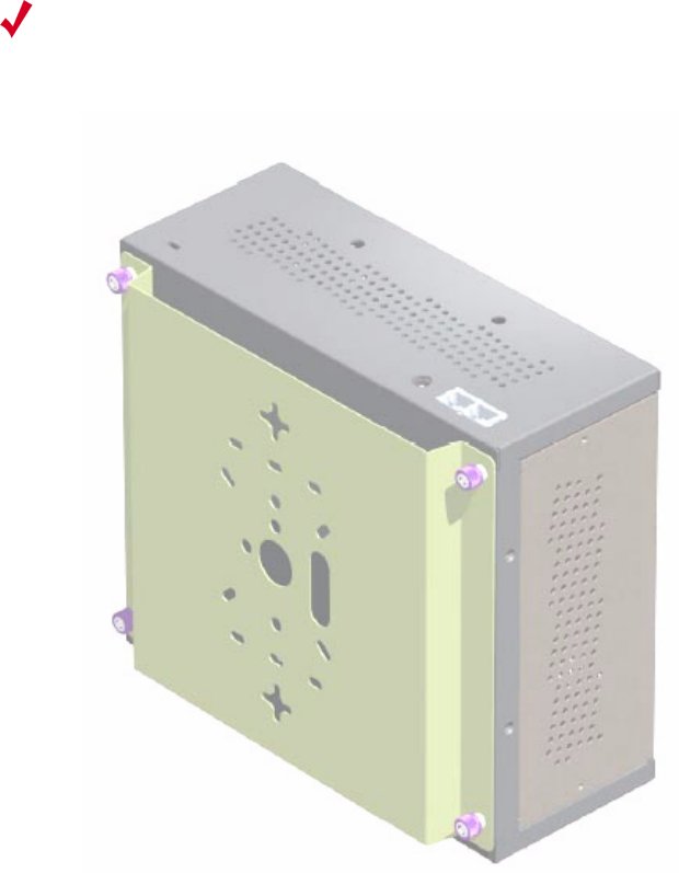
1. Remove the bracket from back side the RS4000 if it is attached by unscrewing each of the 4
knurled thumbscrews (see Figure 2).
12 Meru Radio Switch RS4000 Reference Guide
Performing the Installation
2. Choose the location on the wall where the RS4000 will be mounted. The RS4000 can be oriented
in any direction, but it is probably more convenient if the SMA antenna mounts are at the top. This
orientation is more convenient for reading LED status.
3. Using the bracket holes as a template, mark the location on the wall for the two RS4000 bracket
mounting screws. They are placed 5 25/32" (147mm) apart, center-to-center, one above the other.
If you are not using plastic wall anchors, you must center the mounting screws on a wall stud.
Figure 2: Bracket Attached to RS4000
4. Drill holes at the locations you marked:
—3/16-inch holes if you are using plastic anchors
—1/8-inch holes if you are using only the screws
5. If you are using plastic anchors, install them in the holes.
6. Screw in the screws most of the way, so that the screw head is about 1/16 of an inch from the wall.
Note:
The RS4000 mounting bracket provides holes to accommodate many types of common
installations such as over a junction box, etc. This procedure describes only the standard wall mount.
Performing the Installation
Installing the RS4000 13
7. Mount the bracket on the screws, placing the circular portion of the keyhole mounts over the
screw heads and sliding the bracket down.
8. Tighten the screws to secure the bracket.
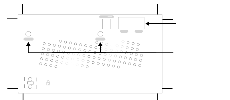
9. On the RS4000, attach the two antenna cables to the SMA antenna connectors labeled ANT 1 and
ANT 2 on the top panel of the RS4000 (see Figure 4) by turning the cable ends clockwise until
tight.
10. Attach two Ethernet cables to the Ethernet ports labeled ETH 1 and ETH 2 on the top panel of the
RS4000.
11. Align the RS4000 to the bracket (against the wall) and tighten the four knurled thumbscrews until
secure. If necessary, apply extra tightening with pliers.
12. Attach the antenna cables to the antenna, as described in “Placing and Positioning the
Antenna.”
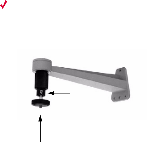
13. Connect the two Ethernet cables to the PoE device.
Placing and Positioning the Antenna
The RS4000 antenna should be mounted to the wall within 6’ of the RS4000 using a standard camera
bracket with 1/4-20 mounting screw. The optional Light-Duty Camera Mount bracket (part number
MN-ACC-RS4000-WCM) is available from Meru Networks. The recommended orientation is shown
in Figure 3.
Figure 3: Antenna Mounting Bracket
The RS4000 antenna uses two 6’ RF cables to connect to the SMA connectors on the top panel of the
RS4000 (see Figure 4). The RF cables should be attached to the RS4000 as a result of the procedures
described in “Wall Mounting the RS4000.”
Mount the antenna and connect the cables as described in the following:
1. Using the screwholes in the mounting bracket as a template, mark and drill holes into the wall.
2. Attach the bracket securely with three 1/4" diameter fasteners or one 5/16" diameter and one 1/4"
diameter fastener if mounting to a wall stud (fasteners are not supplied).
3. Connect the RF antenna wires from the RS4000 to the SMA connectors on the top of the antenna.
Set screw on swivel head
1/4-20 Threaded stud

14 Meru Radio Switch RS4000 Reference Guide
Performing the Installation
4. Attach the top of the antenna to the 1/4-20 threaded stud on the swivel head and tighten the nut
against the antenna.
5. Loosen the set screw on the swivel assembly, if necessary, with the Allen wrench that is provided.
6. Position the antenna to maximize the reception and tighten the set screw.
Hoffman Enclosure RS4000 Installation
Use the procedures in this section to mount the RS4000 within the Hoffman enclosure. It will be
necessary to modify the Hoffman enclosure by drilling cable pass-through holes before installing the
RS4000.
Creating Cable Pass-through Holes in the Hoffman Enclosure
To create cable pass-through holes in the Hoffman enclosure, Meru supplies a template with markings
that coincide with the placement of the Ethernet and antenna cable locations on the RS4000.
Depending on the orientation of the RS4000 installation in the Hoffman enclosure, the template is to
be used on the side of the enclosure adjacent to the RS4000 top panel, where the cables connect.
1. Open the lid of the empty Hoffman enclosure to provide unimpeded access to the enclosure sides.
2. On the outside of the empty Hoffman enclosure, locate the top center of the side where the cables
will exit.
3. Using the pattern on the supplied template, mark the center of the holes and drill a 1/2" to 1" hole
at each of the three locations specified by the template.
Mounting the RS4000 in the Hoffman Enclosure
To mount the RS4000 in the Hoffman enclosure, it is necessary to use the mounting plate that is
supplied with the RS4000 packing items. This procedure assumes the Hoffman enclosure is already
mounted at the site.
1. Remove the bracket from back side the RS4000 if it is attached by unscrewing each of the 4
knurled thumbscrews.
2. Attach the mounting plate to the back of the RS4000 with four 6-36 screws. The plate is larger
than the RS4000, and the overlap portion has screw holes that match up with the screwholes in
the Hoffman enclosure.
3. Attach the two antenna cables to the SMA antenna connectors labeled ANT 1 and ANT 2 on the
top panel of the RS4000 (see Figure 4) by turning the cable ends clockwise until tight.
Note:
The recommended Meru installation is a vertical wall mount, which allows for unimpeded
air flow through the unit. The option to install the RS4000 within a Hoffman enclosure is left to the
customer’s discretion, based on site-specific factors such as protection and accessibility, etc.
Installation in the Hoffman enclosure requires drilling air vents and cable pass-through holes.
Performing the Installation
Installing the RS4000 15
Figure 4: RS4000 Top Panel
4. Attach two Ethernet cables to the Ethernet ports labeled ETH 1 and ETH 2 on the top panel of the
RS4000.
5. Place the RS4000 into the Hoffman enclosure, and align the plate screwholes with the holes in the
Hoffman enclosure.
6. Pass the Ethernet and antenna cables out of the Hoffman enclosure through the cable pass-through
holes, if necessary.
7. Tighten the captive screws on the mounting plate to the Hoffman enclosure.
8. Attach the antenna cables to the antenna.
9. Position and align the bottom of the antenna over the threaded stud on the antenna mount arm and
tighten the threaded stud to the antenna.
10. Test the reception for the antenna and then securely tighten the antenna.
11. Close the lid to the Hoffman enclosure and secure the lock.
12. Connect the two Ethernet cables to the PoE device.
Power On Components
Apply power to the PoE component and network switch to power up the RS4000. Continue with the
software configuration in the next chapter.
ETH 1ETH 1
5V DC
ETH 2ETH 2
ANT 2ANT 2ANT 1ANT 1
ETH 1 and ETH 2
ANT 1 and ANT 2
16 Meru Radio Switch RS4000 Reference Guide
Performing the Installation
Checking LED Activity
Radio switch status LEDs are provided on the face of the RS4000.
RS4000 Status LEDs
Status LEDs on the face of the RS4000 light, as shown in Figure 5.
.
Figure 5: RS4000 Status LEDs
The RS4000 uses 4 LEDs. The functions of the status LEDs are described in Table 3.
RADIO II
ETHERNET
POWER
RADIO II
ETHERNET
POWER
RADIO IRADIO I

Performing the Installation
Installing the RS4000 17
Table 3: RS4000 LED Descriptions
LED Function
Power The Power status LED status is as follows:
zoff—power is off
zsolid red—when power is applied, system initializes for 40 seconds and then
LED turns green; otherwise, system is in an abnormal state (notify Customer
Support)
zsolid amber—at any time, if this LED state persists longer than 40 seconds,
notify Customer Support
zsolid green—system is fully operational
Radio I The Radio I LED is lit when radio packets are being transmitted and when the
radio is beaconing.
Radio II The Radio II LED is lit when radio packets are being transmitted and when the
radio is beaconing.
Ethernet The Ethernet LED status is as follows:
zoff—no link
zsolid green—100Mbps connection
zblinking green—transmit or receive activity at 100Mbps
zsolid amber—10Mbps connection
zblinking amber—transmit or receive activity at 10Mbps
18 Meru Radio Switch RS4000 Reference Guide
Performing the Installation

Configuring the Meru RS4000 19
Chapter 3
Configuring the Meru RS4000
The configuration of the RS4000 includes the following procedures:
zDetermine How the RS4000 Is To Be Managed
zConfiguring of the Radio Switch with the CLI Commands
zActivating and Saving Changes
Determine How the RS4000 Is To Be Managed
The RS4000 can be managed remotely with third-party SNMP Manager software or directly with the
CLI via a Telnet or SSH connection.
Using the CLI with a Telnet/SSH Connection
Using the IP address configured in Initial Configuration of the RS4000, start a Telnet or SSH session
using the newly configured IP address for your RS4000.
After the session is established, you will be prompted to log on. Use the default admin login name
with the newly assigned password, or the default admin password, admin, if you did not change the
password.
Once you have successfully logged in with the admin user ID, you have a full privilege to all CLI
commands. A complete listing of the CLI commands, their keywords and arguments, can be found in
Appendix A, “Command Reference.”
Using SNMP
The RS4000 contains SNMP agent software that can be utilized by a standard SNMP manager to
communicate with and manage the RS4000. The complete set of Meru Enterprise MIB Tables are
listed in Appendix B, “MIB Definition Reference.” By default SNMP access is enabled.
Note:
A maximum of two Telnet/SSH connections are allowed to the RS4000 at any time.

20 Meru Radio Switch RS4000 Reference Guide
Determine How the RS4000 Is To Be Managed
To start using SNMP, the following needs to be established:
zThe IP address and community string of the server running the SNMP manager that can establish
Read Only sessions.
zThe IP address and community string of the server running the SNMP manager that can establish
Read Write sessions.
When configuring the SNMP manager access, you can allow specific managers SNMP access by
defining the IP address of that manager, or allow all SNMP managers access, by using the default IP
address 0.0.0.0.
Configuring the SNMP Manager Settings
The commands to allow the SNMP Manager to communicate with the agent that resides in the RS4000
establish the type of SNMP operations the manager can perform. The SNMP manager can be
configured for ReadOnly operations, which allow SNMP get operations, or ReadWrite, which allow
SNMP get/set operations. Using the ReadWrite access allows remote configuration of the RS4000,
when used with the writable MIB objects.
Configuring ReadOnly Managers
The following commands enable ReadOnly communication (1), and set the IP address and community
string (used as a password) for an SNMP manager at IP address 192.168.200.100:
# set snmpcommunity ROPrivilege 1
# set snmpcommunity ROCommunityString CatsCradle
# set snmpcommunity ROManagerIpAddress 192.168.200.100
To allow all SNMP managers in the network to have read access, do not use the command set
snmpcommunity ROManagerIpAddress. Instead, the default setting 0.0.0.0 is used to allow all
SNMP managers with the community string CatsCradle.
Configuring ReadWrite Managers
The following commands enable ReadWrite communication (1), and set the IP address and
community string (used as a password) for an SNMP manager at IP address 192.168.300.100:
# set snmpcommunity RWPrivilege 1
# set snmpcommunity RWCommunityString CatsCradle
Caution!
As shipped, the system is set with a default password and default SNMP community
strings that allow documented access to the management interfaces. It is strongly recommended that
you change these default settings as soon as possible to prevent unauthorized access to your system.
The commands to perform these changes follow.
Note:
If need be, the default IP address can be reset by using the 0.0.0.0 address as argument to
the IP address command (snmpcommunity ROManagerIpAddress).

Configuring of the Radio Switch with the CLI Commands
Configuring the Meru RS4000 21
# set snmpcommunity RWManagerIpAddress 192.168.300.100
To allow all SNMP managers in the network to have read/write access, do not use the command set
snmpcommunity ROManagerIpAddress. Instead, the default IP address setting 0.0.0.0 is used to
allow all SNMP managers with the community string CatsCradle to get/set MIB objects.
Configuring of the Radio Switch with the CLI Commands
This section describes additional commands to configure the RS4000, as shown in following sections:
zConfiguring the WLAN Parameters
zConfiguring an ESSID
zConfiguring System Security
zConfiguring Radio Parameters
Configuring the WLAN Parameters
The set wif command performs the configuration of the wireless and security properties for the
interface. An interface must be specified in each of the commands and the radio interface determines
the 802.11 operating mode and some associated features. For example, radio1-1 and radio1-2 operate
in mode 802.11a and radio2-1 and radio2-2 operate in either 802.11bg or b mode.
To see the default settings, use the show factoryconfig command. .
meru_ap# show factoryconfig
[system_config]
host_name=meru_ap
syslog_server=
[network_config]
boot_proto = static
ip_addr = 192.168.1.1
mask = 255.255.255.0
def_gateway=
domain=
dns1=
dns2=
dns3=
dns4=
Note:
If need be, the default IP address can be reset by using the 0.0.0.0 address as argument to
the IP address command (snmpcommunity RWManagerIpAddress).
22 Meru Radio Switch RS4000 Reference Guide
Configuring of the Radio Switch with the CLI Commands
[radio1-1]
status = up
essid = meru1-1
mode = 11a
channel = 36
rate = auto
tx_power = 30
rts_threshold = 2312
dtim_period = 1
publish_ssid = enable
beacon_interval = 100
vlan_tag = 0
[radio2-1]
status = up
essid = meru2-1
mode = 11g
channel = 1
rate = auto
tx_power = 30
rts_threshold = 2312
short_preamble = enable
dtim_period = 1
publish_ssid = enable
beacon_interval = 100
vlan_tag = 0
[radio1-2]
status = up
essid = meru1-2
mode = 11a
channel = 149
rate = auto
tx_power = 30
rts_threshold = 2312
dtim_period = 1
publish_ssid = enable
beacon_interval = 100
vlan_tag = 0
[radio2-2]
status = up
essid = meru2-2
mode = 11g
channel = 11
rate = auto
tx_power = 30
rts_threshold = 2312
short_preamble = enable
dtim_period = 1
publish_ssid = enable
beacon_interval = 100
vlan_tag = 0
[wifsec_radio1-1]
Configuring of the Radio Switch with the CLI Commands
Configuring the Meru RS4000 23
security_mode = none
wep_security_mode = shared
wep_key_len = wep64
tx_key_idx = 1
rekey_period = 300
reauth_period = 3600
[wifsec_radio2-1]
security_mode = none
wep_security_mode = shared
wep_key_len = wep64
tx_key_idx = 1
rekey_period = 300
reauth_period = 3600
[wifsec_radio1-2]
security_mode = none
wep_security_mode = shared
wep_key_len = wep64
tx_key_idx = 1
rekey_period = 300
reauth_period = 3600
[wifsec_radio2-2]
security_mode = none
wep_security_mode = shared
wep_key_len = wep64
tx_key_idx = 1
rekey_period = 300
reauth_period = 3600
[radius]
primary_server_ip = 10.0.0.1
primary_server_port = 1812
secondary_server_ip = 10.0.0.2
secondary_server_port = 1812
[load_balancing]
action = start
interval = 1000
mode = strict
[snmp_agent]
sysContact = RSswitchApAgent
sysName = meru_ap
sysLocation = meru_ap
read_com_str = public
read_mgr_ip = 0.0.0.0
read_com_access = read
write_com_str = test2
write_mgr_ip = 0.0.0.0
write_com_access = write
trap_com_str = test2
trap_mgr_ip = 10.0.0.21
uname = admin
24 Meru Radio Switch RS4000 Reference Guide
Configuring of the Radio Switch with the CLI Commands
upasswd = admin
Configuring an ESSID
The RS4000 allows each of the interfaces to have a separate ESSID. By default, meru1-1 is specified
for radio1-1 and meru1-2 for radio1-2; meru2-1 is specified for radio2-1 and meru2-2 for radio2-2.
To change the ESSID, for example to chemestry_lab, use the following commands:
# set wif radio2-1 essid chemestry_lab
# set wif radio2-2 essid chemestry_lab
Configuring System Security
The RS4000 security options include WEP-128 and WEP-64 encryption and 802.1X authentication
and encryption with PEAP. Procedures to configure these features are described in the following
sections.
Setting WEP Parameters
To configure radio2-1 for WEP128, with key index 2 and the hex key 135792468011:
# set wif radio2-1 security_mode wep
# set wif radio2-1 key_index 2
# set wif radio2-1 key1 0x1357924680111
Setting 802.1X Interoperability
The following commands set the primary RADIUS server IP address to 10.0.0.30, with a shared secret
of 2for10is, and port 1812.
# set radius primary_ip 10.0.0.30
# set radius primary_secret 2for10is
# set radius primary_port 1812
To configure radio1-1for 802.1X security:
# set wif radio1-1 security_mode 8021x
The default settings of 3600 seconds for a reauthentication period and 300 seconds for a rekey interval
are used.
Configuring Radio Parameters
Operating parameters for radio settings such as the channel, rate, transmit power, and short preamble
can be changed for each radio interface. The available settings are determined by the radio band
present on the interface, for example, 802.11bg interfaces have channels 1-11 and 802.11a have
channels 36, 40, 44, 48, 52, 56, 60, 64, 149, 153, 157, 161, 165.
For this release of product, following channel usage is recommended:

Activating and Saving Changes
Configuring the Meru RS4000 25
For 802.11bg radios:
zChannel 1 and Channel 11
For 802.11a radios, use any of the following combinations:
zChannel 36 and Channel 48
zChannel 40 and Channel 52
zChannel 44 and Channel 56
zChannel 48 and Channel 60
zChannel 52 and Channel 64
# set wif radio1-1 channel 36
# set wif radio1-2 channel 48
# set wif radio2-1 channel 1
# set wif radio2-2 channel 11
The following commands set rates for 802.11bg interfaces and 802.11a
interfaces:
# set wif radio1-1 rate 24
# set wif radio1-2 rate 36
# set wif radio2-1 rate 6
# set wif radio2-2 rate 11
The following commands set power for 802.11bg interfaces and 802.11a interfaces:
# set wif radio1-1 tx_power 15
# set wif radio1-2 tx_power 15
# set wif radio2-1 tx_power 15
# set wif radio2-2 tx_power 15
The following commands set long preamble for 802.11bg interfaces:
# set wif radio2-1 short_preamble disable
# set wif radio2-2 short_preamble disable
Activating and Saving Changes
After making your configuration changes, it is necessary to activate them using the command
activate-conf. Changes are then propagated and started on all radios and will continue running until
the system is rebooted.
To make sure changes are retained after a system reboot, you must save the active (running)
configuration to a startup configuration file, using the command save-conf.
26 Meru Radio Switch RS4000 Reference Guide
Activating and Saving Changes

Managing and Monitoring the RS4000 27
Chapter 4
Managing and Monitoring the RS4000
This chapter describes tasks to maintain optimal operating conditions and monitor the performance of
the RS4000.
Managing the RS4000
An important part of maintaining optimal performance for the RS4000 is performing image upgrades
as they become available from Meru. This section describes the steps to obtain an upgrade image from
the Meru FTP site and then apply the image to upgrade the RS4000.
Another helpful procedure is to keep a copy of the working configuration at another site for
safekeeping. The procedure to upload the configuration file to a remote server is also described.
Saving the Configuration to a Remote Server
Best practice recommendations include saving a copy of the configuration to a remote server to
safeguard against accidental removal or destruction of a valid working configuration. To send a
configuration to a remote server (for example 10.0.220.58), use the following command:
# upldconf tftp_ip 10.0.220.58
Upload of nms.conf complete
Upgrading the System Software
Upgrading the system software is recommended when new images are released from Meru that
include additional features or fixes. The images are usually located on the Meru Networks FTP site.
The steps to perform an upgrade to the RS4000 software follow:
1. Be sure to save your running configuration (if you want to keep any changes you made to this
point):
Note:
Configuration files that are saved off-box should not be edited with a text editor. The only
changes to the configuration file should result from changes made on the RS4000, using
the CLI commands.

28 Meru Radio Switch RS4000 Reference Guide
Monitoring the RS4000
# save-conf
Configuration Saved Successfully!
2. As a best practice, ensure that your configuration is backed up to a remote server:
# upldconf tftp_ip 10.0.220.58
Upload of nms.conf complete
3. Use the download command to download a new new software image file into the RS4000 flash
memory. In the following example, the image RS4000_pkg_11_0_06.tar resides on the server at
10.0.220.58
# download ip 10.0.220.58 image RS4000_pkg_11_0_06.tar
Download Complete
4. Use the upgrade local command to upgrade the current image to the newly downloaded image:
# upgrade local image RS4000_pkg_11_0_06.tar
Upgrade Complete
5. The RS4000 automatically reboots as part of the upgrade procedure. Wait 2-3 minutes and
reconnect via telnet or SSH and log in as admin.
Meru RS4000 (00:01:02)
(c) 2004 Meru Networks, Inc.
All Rights Reserved
Unauthorized access or use of this system is strictly prohibited.
meru_ap login: admin
Password:
RS4000 v1.00-pre10 (2005.06.20-15:40+0000) Built-in shell (ash)
Enter 'help' for a list of built-in commands.
6. Check RS4000 configuration after reboot.
# show running-conf
Monitoring the RS4000
Various show commands allow you to check the system configuration and statistics to monitor the
system performance.
Checking System Details
To check the basic system details, use the commands show system and show wif:
# show system
Monitoring the RS4000
Managing and Monitoring the RS4000 29
[system]
Description : Access Point
Up Time(hh:mm:ss.ff) : 04:30:23.41
Contact : RSswitchApAgent
Name : meru_ap
Location : meru_ap
Serial Number : 00:10:C6:AA:11:13
AP Type : RS4000
Boot Version : 1.0
Software Version : 1.1-131
Host Name : meru_ap
Syslog Server : 0.0.0.0
# show wif
[radio1-1]
ESSID : cwon-testap
Operational Mode : 11a
Rate : auto
Channel : 36
Short Preamble : disable
Tx Power : 30
ESS Vlan Tag : 0
DTIM Period : 1
Publish ESSID : enable
Beacon Interval : 100
Rekey Period : 300
Re-authentication Period : 3600
Key Length : wep128
Security Mode : WEP
Transmission Key Index : 1
Wep Security Mode : shared
WEP Key1 : **************
WEP Key2 : **************
WEP Key3 : **************
WEP Key4 : **************
(and so on, for each radio interface)
Checking Syslog Messages
Syslog messages are generated and sent to the log file on the syslog server that is configured with the
set system syslog_server IP_address command. These message are sent when critical events occur
in the WLAN. A sample syslog message follows:
03072005_RS_SYSLOG_10

30 Meru Radio Switch RS4000 Reference Guide
Monitoring the RS4000
The list of syslog messages are as follows:
Checking Security Options
Check the settings for the security options using the show wif and show radius commands. Check the
example output of the show wif command above. Included are the Security Mode settings (WEP or
802.1X), and the various details that are determined by the mode selected. For example, the WEP
Keys, Key Index position, and so forth.
If 802.1X is selected, the RADIUS settings for the primary and secondary server can be checked with
the show radius command:
meru_ap# show radius
[radius]
IP Address Primary RADIUS Server : 10.0.0.1
Port of Primary RADIUS Server : 1812
Shared Secret of Primary RADIUS Server : *********
IP Address Secondary RADIUS Server : 10.0.0.2
Port of Secondary RADIUS Server : 1812
Shared Secret of Secondary RADIUS Server : *********
Checking Network Settings
Use the show ip command to check the network settings:
# show ip
Network Configuration:
03072005_RS_SYSLOG_10 Radio Switch has successfully booted. This message contains
the IP address and MAC address of the Radio Switch and also
Identifies the device type as RS4000.
03072005_RS_SYSLOG_20 FLASH corruption has occurred. The software is then reset to
factory defaults.
03072005_RS_SYSLOG_30 An upgrade process has been initiated on the RS4000.
03072005_RS_SYSLOG_40 An upgrade process has been successfully completed on the
RS4000.
03072005_RS_SYSLOG_50 An upgrade process has failed on the RS4000.
03072005_RS_SYSLOG_60 The admin user has logged into the RS4000.
03072005_RS_SYSLOG_70 The admin user has logged out of the RS4000.
03072005_RS_SYSLOG_80 The admin user is unable to log into the RS4000.
03072005_RS_SYSLOG_90 The RADIUS server has switched from Primary to Secondary
or vice versa. The IP address of the RADIUS Server to which
the switch is made is included.
Monitoring the RS4000
Managing and Monitoring the RS4000 31
----------------------
Boot Protocol : dhcp
IP Address : 172.16.0.74
Network Mask : 255.255.0.0
Default Gateway : 172.16.0.1
Domain : merunetworks.com
DNS1 :
DNS2 :
DNS3 :
DNS4 :
Checking whether you have connectivity with the network can be checked with the ping command,
once you see the IP address of the RS4000:
ping 172.16.0.74
Checking Wireless Statistics
To check the wireless statistics for the entire Radio Switch, use the show dot11counters command
(see the command reference page, “show dot11counters” on page 69 for descriptions of the various
statistics).
You can also check statistics for a particular interface by specifying that interface (radio1-1, for
example), as shown in the following example:
# show dot11counters radio1-1
[radio1-1]
Transmitted Fragment Count : 0
Multicast Transmitted Frame Count : 0
Failed Count : 26688
Retry Count : 296975
Multiple Retry Count : 0
Frame Duplicate Count : 217
RTS Success Count : 0
RTS Failure Count : 0
ACK Failure Count : 0
Received Fragment Count : 0
Multicast Received Frame Count : 0
FCS Error Count : 2861434
Transmitted Frame Count : 433603
WEP Undecryptable Count : 0
32 Meru Radio Switch RS4000 Reference Guide
Monitoring the RS4000
Command Reference 33
Appendix A
Command Reference
This appendix provides complete descriptions of the commands that are available from the
CLI prompt. The following alphabetically lists the available commands:
z?
zactivate-conf
zdldconf
zdownload
zformat
zhistory
zhelp
zpasswd
zquit
zreboot
zreset-to-default
zsave-conf
zset configsnmp
zset interfaces
zset ip
zset loadbalance
zset radius
zset snmpcommunity
zset system
zset wif
zsetenv
zshow assocStations
zshow configsnmp
zshow dot11counters
zshow factoryconfig
zshow history
zshow interfaces
zshow ip
zshow led
zshow loadbalance
zshow radius
zshow runningconfig
zshow snmpcommunity
zshow startupconfig
zshow system
zshow unsavedconfig
zshow wif
zupgrade
zupdldconf

34 Meru Radio Switch RS4000 Reference Guide
?
Displays help for the CLI.
Syntax ?
Usage Use the ? to display online help for all commands or for a single command to show the
available keywords and parameters. The ? can be used at any point on the command line to
receive help at that point.
Examples Use the following command to display all available commands:
# ?
help -> Display this message
show -> Display system state and configuration information
set -> Issue a single configuration command
format -> Set output display format to CLI Table, CLI Pretty or
CLI Plain
history -> Display list of previous commands
setenv -> Set CLI session environment variables
quit -> Exit the CLI
upgrade -> Upgrade system image
upldconf -> Upload system configuration
dldconf -> Download system configuration
save-conf -> Save Running(Active) configuration in flash
activate-conf -> Activate(Apply) unsaved configuration
reset-to-default -> Reset system configuration to factory
default
reboot -> Reboot system
passwd -> Changes password
Use the TAB key for unique command completion, the ? key for help,
the up/down arrow keys to cycle through previous commands, and
Ctrl-U to kill the current line.
Use the following command to display help for the set system command:
#set system ?
system [Contact <value>] [Name <value>] [Location <value>] [hostname
<value>] [syslog_server <value>]
Related
Commands
help

Command Reference 35
activate-conf
Activates the changes made to the current configuration.
Syntax activate-conf
Usage Use this command to activate recently configured parameter changes that have been made to
the system. Once activated with this command, the configuration changes are active but are
temporary and only valid for the current session. Changes must be saved with the command
save-conf if the system is to retain these changes after a system is reboot.
To see the configuration once it has been activated, use the command show running-conf. To
see unsaved configuration changes, use the command show unsaved-conf. To see the saved
configuration, use the command show start-conf.
Examples Use the following command to activate the current configuration:
# activate-conf
Related
Commands
save-conf
reboot
show runningconfig
show startupconfig

36 Meru Radio Switch RS4000 Reference Guide
dldconf
Downloads a configuration file.
Syntax dldconf tftp_ip ip_address
Usage Use this command to retrieve and download a configuration file that is located on a remote
TFTP server, specified by the ip-address argument.
To successfully complete the download, before this command is invoked, the configuration
file, nms.conf, should be copied to the /tftpboot directory on the TFTP server, which is the
default file access location used by the TFTP protocol.
Once the download is complete, the configuration file is stored on the RS4000 but is not used
until it is activated with the activate-conf command. As with all running configurations, to
ensure the configuration is saved and started with the next reboot, use the save-conf
command.
Examples Use the following command to download the configuration file from the TFTP server at
192.168.10.220:
# dldconf tftp_ip 192.168.10.220
Related
Commands
activate-conf
save-conf
ltftp_ip ip_address Specifies the IP address of the TFTP server where the
configuration file is located.
Note:
Configuration files that are saved off-box should not be edited with a text
editor. The only changes to the configuration file should result from
changes made on the RS4000, using the CLI commands.

Command Reference 37
download
Downloads a software image.
Syntax download ip tftp_ip_address image file
Usage The download command downloads a system image file from a remote TFTP server,
specified by its IP address. The file is downloaded to the RS4000 flash memory for use for a
future system upgrade, using the upgrade command.
Examples The following example downloads an upgrade image (RS4000_pkg_11_0_06.tar) from the
TFTP server at 10.0.220.58:
download ip 10.0.220.58 image RS4000_pkg_11_0_06.tar
Related
Commands
upgrade
ip tftp_ip_address Specifies the IP address of the TFTP server where the
image file is obtained.
image file Package (file) name to be used as the upgrade image.

38 Meru Radio Switch RS4000 Reference Guide
format
Formats the output of the show command.
Syntax format {clipretty | cliplain | clitable}
Usage Use this command to format the output of the show command. Each of the keywords formats
the output differently and are used to accommodate how the output is used.
Typically, the clitable keyword is used for the standard table view of output information. The
keywords cliplain and clipretty may be used if the output will be used as input to another
process.
Examples The following shows how the same output is presented using the three keywords:
meru-ap# format clitable
meru_ap# show wif
[radio1-1]
ESSID : cwon-testap
Operational Mode : 11a
Rate : auto
Channel : 36
Short Preamble : disable
Tx Power : 30
ESS Vlan Tag : 0
DTIM Period : 1
Publish ESSID : disable
Beacon Interval : 100
Rekey Period : 300
Re-authentication Period : 3600
Key Length : wep128
Security Mode : WEP
Transmission Key Index : 1
Wep Security Mode : shared
WEP Key1 : **************
WEP Key2 : **************
WEP Key3 : **************
WEP Key4 : **************
clipretty Formats output with some amount of white space separation.
cliplain Formats output with very little white space separation.
clitable Formats output with white space separation that facilitates
readability.
Command Reference 39
meru_ap# format clipretty
meru_ap# show wif
wif {
row[3] {
essid "cwon-testap"
mode 11a rate auto
channel 36 short_preamble disable tx_power 30
ess_vlantag 0 dtim_period 1 publish_essid disable
beacon_interval 100 rekey_period 300 reauth_period
3600 key_len wep128 security_mode WEP
key_index 1 wep_auth_mode shared key1
"**************"
key2 "**************"
key3 "**************"
key4 "**************"
}
meru_ap# format cliplain
meru_ap# show wif
wif 3 essid "cwon-testap"
wif 3 mode 11awif 3 rate auto
wif 3 channel 36wif 3 short_preamble disablewif 3 tx_power 30wif 3
ess_vlantag 0wif 3 dtim_period 1wif 3 publish_essid disablewif 3
beacon_interval 100wif 3 rekey_period 300wif 3 reauth_period
3600wif 3 key_len wep128wif 3 security_mode WEPwif 3 key_index
1wif 3 wep_auth_mode sharedwif 3 key1 "**************"
wif 3 key2 "**************"
wif 3 key3 "**************"
wif 3 key4 "**************"

40 Meru Radio Switch RS4000 Reference Guide
history
Displays a history of commands entered.
Syntax history
Usage Shows the 12 most recent commands. Use the up arrow to scroll through the previous
comments, starting with the most recent. While scrolling, use the down arrow to move back.
The history buffer contains the last 12 commands entered at the command line.
Examples The following shows the history of commands entered at the command line:
meru_ap# history
show snmpcommunity
history
setenv
history
Related
Commands
show history

Command Reference 41
help
Displays help for the CLI.
Syntax help
Usage Use the help command to display a list of commands that are available at the prompt. For
example, show all commands at the top level, show all the set commands, or all show
commands.
Examples Use the following command to display all available commands:
# help
help -> Display this message
show -> Display system state and configuration information
set -> Issue a single configuration command
format -> Set output display format to CLI Table, CLI Pretty or
CLI Plain
history -> Display list of previous commands
setenv -> Set CLI session environment variables
quit -> Exit the CLI
upgrade -> Upgrade system image
upldconf -> Upload system configuration
dldconf -> Download system configuration
save-conf -> Save Running(Active) configuration in flash
activate-conf -> Activate(Apply) unsaved configuration
reset-to-default -> Reset system configuration to factory
default
reboot -> Reboot system
Use the TAB key for unique command completion, the ? key for help,
the up/down arrow keys to cycle through previous commands, and
Ctrl-U to kill the current line.
Related
Commands
?

42 Meru Radio Switch RS4000 Reference Guide
passwd
Changes the system password.
Syntax passwd new-password
Usage Use this command to change the current password. Initially, the system password is set to
admin. This should be changed immediately to prevent unauthorized access to the system.
Once the password is changed, it takes effect immediately (usually the command activate-
conf must be used to activate a change). However, the password is active only for the current
session. To save the password so it remains in affect after a reboot, it must followed with the
commands activate-conf and save-conf.
Examples Use the following command to change the current password, the default password admin, in
this case:
# passwd new_password
Changing password for admin
Old password: admin
Re-enter new password: new_password
Password changed.
Related
Commands
activate-conf
save-conf
Note:
The system checks for passwords that are too simple or similar.

Command Reference 43
quit
Exits the CLI.
Syntax quit
Usage Use the quit command to exit the CLI session.
Examples The following command gracefully exits from the CLI session:
# quit

44 Meru Radio Switch RS4000 Reference Guide
reboot
Reboots the system.
Syntax reboot
Usage Use this command to reboot the system and restart the system with the configuration that was
last saved with the command save-conf.
Examples Use the following command to reboot the system:
# reboot
Related
Commands
save-conf

Command Reference 45
reset-to-default
Reboots the system to the factory default settings.
Syntax reset-to-default
Usage Use this command to reboot the system and restart the system with the factory-set default
settings. It may be helpful to use this command when an ill-advised configuration puts the
system in an unrecoverable situation.
Examples Use the following command to reset the system to default settings:
# reset-to-default

46 Meru Radio Switch RS4000 Reference Guide
save-conf
Saves the current configuration.
Syntax save-conf
Usage Use this command to save the current running configuration to permanent system memory.
After the configuration is saved with this command, the next time the system boots, the system
starts running with the just-saved configuration. The system configuration is stored in the
system file nms.conf.
Examples Use the following command to save the current configuration:
# save-conf

Command Reference 47
set configsnmp
Enables or disables the SNMP trap collection activity.
Syntax set configsnmp SnmpTrapEnable {1 | 2}
Usage Use this command to enable or disable the collection of SNMP traps. Using this command
requires that the SNMP community settings are configured with the set snmpcommunity
command
Examples Use the following command to enable SNMP trap collection:
# set configsnmp SnmpTrapEnable 1
Related
Commands
set snmpcommunity
set trapcommunity
SnmpTrapEnable 1 | 2 Specifies whether SNMP traps are being collected:
z1—Enabled; Traps are being collected.
z2—Disabled; Traps are not being collected.

48 Meru Radio Switch RS4000 Reference Guide
set interfaces
Activates and deactivates interfaces.
Syntax set interfaces if AdminStatus {1 | 2}
Usage Use this command to set a radio interface (for example, radio1-1) status up or down. When
the status is set to 1 (up), the interface is allowed to be brought online. When the status is set
to 2 (down), the interface is unavailable.
Examples Use the following command to enable the interface radio1-1:
# set interfaces radio1-1 AdminStatus 1
Related
Commands
show interfaces
if Specifies the radio interface (if) to configure (radio1-1
| radio2-1| radio1-2 | radio2-2).
Two interfaces (radio1-1 and radio1-2) operate in
mode 802.11a and two interfaces (radio2-1 and
radio2-2) operate in either 802.11bg, b, or g mode.
AdminStatus 1 | 2 Specifies the status mode for the interface. By default,
the interfaces are up.
1—Up; Interface is active and can be brought up
2—down; Interface is inactive and is unavailable

Command Reference 49
set ip
Sets network configuration settings.
Syntax set ip boot_protocol {dhcp | static addr IP_address netmask subnet_address}
set ip gateway IP_address
set ip domain domain_name
set ip dns[1-4] IP_address
Usage The set ip commands set basic networking parameters that the Radio Switch uses to connect
to the network.
First enter the command set ip boot_protocol static addr IP_address netmask
subnet_address or set ip dhcp to establish how the Radio Switch receives its IP address after
booting up. By default, the RS4000 is configured with the IP address/netmask
192.168.1.1/255.255.255.0. With the setting dhcp, the switch automatically receives its IP
address and associated network mask settings, as well as the gateway IP address from the
DHCP server.
If the static keyword is used , the additional keywords and values for addr and netmask must
be given, as well as the set ip gateway command.
The set ip domain command sets the domain name for the network. The set ip dns1through
set ip dns4 commands allow setting up to 4 Domain Name Server IP addresses, where dns1
is the primary server, dns2 is the secondary server, and so forth.
dhcp Specifies that the Radio Switch boots with DHCP. The
default setting is static addressing.
static addr IP_address netmask
subnet_address
Specifies that the Radio Switch boots with the static IP
address specified by IP_address and the netmask
specified by subnet_address . By default, the IP
address is set to 192.168.1.1 and the netmask is set to
255.255.255.0.
gateway IP_address Specifies the gateway IP address that the Radio Switch
uses.
domain domain_name Specifies the domain name of the domain where the
Radio Switch resides. The domain name can be a
maximum of 32 characters.
dns1 IP_address
dns2 IP_address
dns3 IP_address
dns4 IP_address
Specifies up to four different DNS IP addresses.
50 Meru Radio Switch RS4000 Reference Guide
Examples To manually set the Radio Switch IP addressing, use the following example commands:
set ip boot_protocol static addr 10.0.1.100 netmask 255.0.0.0
set ip gateway 10.0.0.20
set ip domain merunetworks
set ip dns1 65.182.161.201
set ip dns2 24.221.161.5
Related
Commands
show ip

Command Reference 51
set loadbalance
Sets the load balancing configuration.
Syntax set loadbalance action {stop | start}
set loadbalance interval milliseconds
set loadbalance mode {strict | smooth}
Usage The load balancing feature evenly distributes clients that attempt to associate with a Radio
Switch, ensuring a fair balance of clients among radios on the same band, and within the same
ESSID. By default, load balancing is active to assure both radios are being used equally. The
balancing is determined by the number of clients assigned to each radio band and ESSID, not
the amount of packets being transferred by each client. Load balancing is performed between
the two radios on the same band and ESSID (that is, between both A radios and between both
BG radios on the same RS4000).
As a client begins to associate, an inventory of the currently associated clients for the
requested band is taken, and based on the type of balancing mode selected (strict or smooth)
the client is assigned to the radio that is next in line to receive a client.
The different load balancing modes, strict and smooth, allocate clients based on a calculation
of the radio that has a lesser number of clients that are associated. The calculation for smooth
uses more of an averaging method than that used for the strict method. By default, the strict
calculation is set.
action 1 | 2 Sets the operational status for load balancing. Available
settings are:
z1 (or stop)—stop load balancing
z 2 (or start)—start load balancing
interval milliseconds Sets the interval in milliseconds for load balancing. The
minimum interval is 10 milliseconds and the default
interval is 1000 milliseconds.
mode {{1|strict}| {2|smooth}} Sets the load balancing mode. Available settings are:
z1 (or strict)—strict load balancing (default setting)
z 2 (or smooth)—smooth load balancing
Note:
By default, four ESSIDs are factory set, meru1-1, meru1-2, meru2-1, and meru-2-
2. These should be removed and two ESSIDs created: each that combine the two
radios per band. See set wif to create ESSIDs.
52 Meru Radio Switch RS4000 Reference Guide
Examples To disable Load balancing:
# set loadbalance action 1
To create two ESSIDs:
# set wif radio1-1 essid bandA
# set wif radio1-2 essid bandA
# set wif radio2-1 essid bandG
# set wif radio2-2 essid bandG
To start the load balancing:
# set loadbalance action 2
Related
Commands
set wif

Command Reference 53
set radius
Specifies the RADIUS server configuration.
Syntax set radius primary_ip ip_addr
set radius primary_port port_number
set radius primary_secret secret
set radius secondary_ip ip_addr
set radius secondary_port port_number
set radius secondary_secret secret
Usage The radius commands configure parameters used to communicate with an existing network
RADIUS server. The RADIUS server is a key component of 802.1X WLAN security, as it
provides access management by checking an access list to authenticate a user that attempts to
join the WLAN. Many sites configure a primary and secondary RADIUS server to ensure the
continued availability of the authentication service, should the primary server become
unavailable.
The RADIUS server IP address must be specified, as well as a shared secret and port number.
Other configuration parameters set with command determine the amount of time a key is valid
before it is automatically changed, and the amount of time clients are allowed to connect to
the Radio Switch before they must reauthenticate themselves.
Examples The following commands set the primary RADIUS server IP address to 10.0.0.30, with a
shared secret of 2for10is, and port 1812.
# set radius primary_ip 10.0.0.30
# set radius primary_secret 2for10is
# set radius primary_port 1812
primary_ip ip_addr
secondary_ip ip_addr
Sets the primary (primary_ip ip_addr) and
secondary (secondary_ip ip_addr) RADIUS server
IP address. By default, 10.0.0.1 is set as the primary
IP address and 10.0.0.2 is set as the secondary.
primary_port port_number
secondary_port port_number
Sets the primary (primary_port port_number) and
secondary (secondary_port port_number)
RADIUS server IP port number. By default, 1812 is
set for both primary and secondary port numbers.
primary_secret secret
secondary_secret secret
Sets the primary (primary_secret secret) and
secondary (secondary_secret secret) RADIUS
server shared secret. A maximum of 32 characters
can be used for secret. By default, meru123 is set
for the primary secret and secondary secret.

Command Reference 55
set snmpcommunity
Sets the SNMP community values.
Syntax set snmpcommunity ROPrivilege {1| 2}
set snmpcommunity ROCommunityString string
set snmpcommunity ROManagerIpAddress IP_address
set snmpcommunity RWPrivilege {1| 2}
set snmpcommunity RWCommunityString string
set snmpcommunity RWManagerIpAddress IP_address
ROPrivilege 1| 2 Specifies whether Read Only privilege to the agent by
authorized managers is enabled or disabled:
z1—Enabled
z2—Disabled
ROCommunityString string Sets the name of the ReadOnly community string,
which is used for authorization and access, similar to a
password. By default, public is set, but any user-
defined 32-character string can be used.
ROManagerIpAddress IP_address Sets the IP address for a ReadOnly SNMP Management
Station. By default, the address is set to 0.0.0.0, which
allows all managers read/get access to the agent. If a
unique IP address is set, only that management station
has access to the agent.
RWPrivilege 1| 2 Specifies whether Read Write privilege is enabled to
the agent:
z1—Enabled
z2—Disabled
RWCommunityString string Sets the name of the ReadWrite community string,
which is used for authorization and access, similar to a
password. By default, test2 is set, but any user-defined
32-character string can be used.
RWManagerIpAddress
IP_address
Sets the IP address for a ReadWrite SNMP
Management Station. By default, the address is set to
0.0.0.0, which allows all managers get/set access to the
agent. If a unique IP address is set, only that
management station has access to the agent.

56 Meru Radio Switch RS4000 Reference Guide
Usage Use this command to define the SNMP community settings. The SNMP application-layer
protocol supports message-oriented communication between SNMP management stations
and the SNMP agent located on the RS4000.
As a prerequisite, SNMP must be enabled using the command set configsnmp. Then use this
command and the privilege, community string, and manager IP address keywords to configure
the SNMP community. There are two types of SNMP communities:
zReadOnly (RO)—allows the manager to read/get the SNMP MIB object values on the
RS4000. This allows an SNMP Management Station to view the status of the RS4000.
zReadWrite (RW)—allows the manager to read and also set SNMP object values on the
RS4000 (except for the community string). Setting object values allows the RS4000 to be
configured remotely from the SNMP Management Station.
The SNMP community string is similar to a password and is used for authentication, privacy,
and authorization services to the SNMP agent.
Examples The following commands enable SNMP ReadOnly permission for the management station at
IP address 192.168.200.100, and uses CatsCradle as the access code:
# set snmpcommunity ROPrivilege 1
# set snmpcommunity ROCommunityString CatsCradle
# set snmpcommunity ROManagerIpAddress 192.168.200.100
Related
Commands
set configsnmp
set trapcommunity
Caution!
As shipped, the system is set with default SNMP community strings (public) that
allow documented access to the management interfaces. It is strongly recommended that you
change these default strings as soon as possible to prevent unauthorized access to your system.

Command Reference 57
set system
Sets system level configuration settings.
Syntax set system Contact name
set system Name RS4000_name
set system Location description
set system hostname hostname
set system syslog_server IP_address
Usage The set system command configure basic system parameters for identifying the RS4000 and
providing its Regulatory Domain setup. Identification text provides labels for a Contact,
Location description, Name of unit, and Hostname assigned to the Radio Switch. It also allows
you to designate the IP address for the system that is to be used as the syslog server.
Examples To configure the hostname of the Radio Switch to library_RS, use the command:
# set system hostname library_RS
To designate the IP address (192.168.220.1 for example) of the system that is to be used as the
syslog server, use the command:
# set system syslog_server 192.168.220.1
Contact name Specifies an identifying name to be used as the contact
reference.
Name RS4000_name Specifies an identifying name for the RS4000.
Location description Specifies descriptive text for where the RS4000 is
located.
hostname hostname Specifies the hostname for the Meru Radio Switch. A
maximum of 32 characters can be used. By default, the
host name is set to meru_ap.
syslog_server IP_address IP address of the system to be used as the syslog server.
The syslog server is the location where the system log
file resides. See “Checking Syslog Messages” on
page 29 for a complete list of messages.
Note:
A complete list of the syslog messages can be found in “Checking Syslog
Messages” on page 29.

Command Reference 59
set trapcommunity
Configures the SNMP trap manager station.
Syntax set trapcommunity TrapCommunityStr string
set trapcommunity TrapCommunityManagerIpAddress IP_address
Usage Use this command to set an SNMP management station IP address and the community string
that serves as a password to protect access to the SNMP management station. The SNMP
management station can receive SNMP traps from the RS4000 SNMP agent.
An SNMP trap is an unsolicited SNMP message that is sent to a management station. Traps
are sent to convey the data immediately, instead of waiting for the station to poll at some future
time.
Examples Use the following command to set the community string that authenticates and authorizes the
SNMP trap manager:
# set trapcommunity TrapCommunityStr alabast0r
Use the following command to set the IP address of the SNMP trap manager:
# set trapcommunity TrapCommunityManagerIpAddress 192.168.100.1
TrapCommunityStr string Sets the name of the trap community string, which
is used for authorization and access, similar to a
password. By default, test2 is set, but any user-
defined 32-character string can be used.
TrapCommunityManagerIpAddress
IP_address
Sets the IP address for a SNMP trap Management
Station. By default, the address is set to 0.0.0.0,
which allows all managers to receive traps from
the agent. If a unique IP address is set, only that
management station can receive traps from the
agent.
Caution!
As shipped, the system is set with documented SNMP trapcommunity strings that
allow access to the management interfaces. It is strongly recommended that you change these
default strings as soon as possible to prevent unauthorized access to your system.

Command Reference 61
set wif
Configures wireless interface settings.
Syntax set wif if essid essid_name
set wif if mode {11a | 11g}
set wif if rate {1 | 2 | 5.5 | 6 | 9 | 11 | 12 | 18 | 24 | 36 | 48 | 54 | auto}
set wif if channel {1-11 | 36 | 40 | 44 | 48 | 52 | 56 | 60 | 64 | 149 | 153 | 157 | 161 | 165}
set wif if short_preamble {enable | disable}
set wif if tx_power 1-30
set wif if ess_vlantag 0-4094
set wif if dtim_period 0-255
set wif if publish_essid {enable | disable}
set wif if beacon_interval 0-65535
set wif if security_mode {none | 8021x | wep}
set wif if reauth_period 0-65535
set wif if rekey_period 0-65535
set wif if key_len {wep64 | wep128}
set wif if key_index {1 | 2 | 3 | 4 }
set wif if wep_auth_mode {shared | open}
set wif if key[1-4] key
if Specifies the radio interface (if) to configure (radio1-1
| radio2-1| radio1-2 | radio2-2).
Two interfaces (radio1-1 and radio1-2) operate in
mode 802.11a and two interfaces (radio2-1 and radio2-
2) operate in either 802.11bg, or b mode.
The interface designation is a mandatory parameter in
all wireless interface commands and is shown as if in
the related command syntaxes.
essid essid_name Specifies the ESSID (Extended Service Set Identifier)
name associated with the radio interface. By default,
ESSID meru1-1 is specified for radio1-1 and meru1-2
for radio1-2; ESSID meru2-1 is specified for radio2-1
and meru2-2 for radio2-2.
The essid_name must be a maximum of 32 characters
and must not contain special characters or spaces. An
ESSID must not mix modes (see below) or load
balancing cannot be performed.
62 Meru Radio Switch RS4000 Reference Guide
mode {11a | 11g} Specifies the operational mode of wireless interface
(11a | 11g). By default, 11a is specified for 802.11a
interfaces (radio1-1 and radio1-2) and 11g is specified
for 802.11bg interfaces (radio2-1 and radio2-2).
When changing the mode, be sure to also change the
rate to correspond.
rate {1 | 2 | 5.5 | 6 | 9 | 11 | 12 | 18 |
24 | 36 | 48 | 54 | auto}
Specifies the transmit data rate (Mbps) of the interface.
By default, auto is set to allow the rate to be set by the
interface mode. Specifically:
z802.11a supports 6 | 9 | 12 | 18 | 24 | 36 | 48 | 54 | auto
z802.11b supports 1 | 2 | 5.5 | 11 | auto
z802.11bg supports 1 | 2 | 5.5 | 6 | 9 | 11 | 12 | 18 | 24 |
36 | 48 | 54 | auto
channel {1-11 | 36 | 40 | 44 | 48 | 52
| 56 | 60 | 64 | 149 | 153 | 157 | 161 |
165}
Specifies the channel (frequency) on which wireless
interface is operating. By default, channel 36 is set for
radio1-1 and 149 for radio1-2 (11a interfaces), and
channel 1 is set for radio2-1 and 11 for radio2-2
(11b/11bg interfaces).
For this release of product, following channel usage is
recommended:
For 802.11bg radios:
zChannel 1 and Channel 11
For 802.11a radios, use any of the following
combinations:
zChannel 36 and Channel 48
zChannel 40 and Channel 52
zChannel 44 and Channel 56
zChannel 48 and Channel 60
zChannel 52 and Channel 64
short_preamble {enable | disable} Specifies whether to enable or disable short preamble.
By default, short preamble can only be enabled if mode
is set to 11g. If short preamble is disabled, long
preamble is used, which may be necessary to ensure
compatibility between the RS and some older WLAN
cards. Using short preamble improves throughput.
stx_power 1-30 Specifies the transmit power level in dBm for the
interface. By default, the power level is set to 30 dBm.
ess_vlantag 0-4094 Specifies the VLAN identification tag to assign to the
interface. Valid tags can be from 0 to 4094. The default
setting is 0.
Command Reference 63
dtim_period 0-255 Specifies the number of beacon intervals that elapse
before broadcast frames are sent. Value must be
between 0 and 255. Setting the DTIM period to a higher
value decreases the frequency of broadcasts sent by the
RS4000. If power save is enabled on clients that are
connected to the RS4000, clients “wake up” less if
fewer broadcasts are sent, which conserves battery life
for the clients. The default beacon DTIM period is 1.
publish_essid {enable | disable} Specifies whether the RS4000 broadcasts the ESSID
(enabled) or not (disabled). By default, an ESSID is
broadcast. When an ESSID is broadcast, it is included
in the beacon that gets advertised. Clients using passive
scanning listen for beacons transmitted by access
points. If broadcasting an ESSID is disabled, clients
listening for beacons cannot receive ESSID
information.
beacon_interval {25-500} Specifies the interval in milliseconds between beacon
broadcasts. Setting the beacon interval to a higher value
decreases the frequency of unicasts and broadcasts sent
by the RS4000. If the power-save feature is enabled on
clients that are connected to the RS4000, clients “wake
up” less if fewer unicasts and broadcasts are sent, which
conserves the battery life for the clients. The default
interval is 100.
security_mode {none | 8021x |
wep}
Specifies the mode that will be used to enforce WLAN
security. The default setting is none.
If 8021x is selected, the 802.1X protocol is used and the
set radius command must also be invoked to set the
RADIUS server configuration parameters.
If wep is selected, the following commands must also
be used to set the WEP parameters:
zset wif if key_len
zset wif if key_index
zset wif if wep_auth_mode
zset wif if key[1-4]
reauth_period 0, 3600-65535 Period in seconds after which 802.1X authenticated
wireless clients will be reauthenticated. By default, the
period is set to 3600 seconds. A value of 0 means
reauthentication is disabled.
64 Meru Radio Switch RS4000 Reference Guide
Usage These commands perform the configuration of the WiFi properties for the interface. The
interface must be specified in each of the commands and the radio interface determines the
802.11 operating mode and some associated features. For example, radio1-1 and radio1-2
operate in mode 802.11a and radio2-1 and radio2-2 operate in either 802.11bg or b modes.
A summary of the default settings for the wireless interface are as follows:
zESSID: meru1-1 is specified for radio1-1 and meru1-2 is specified for radio1-2; meru2-
1 is specified for radio2-1 and meru2-2 is specified radio2-2
zmode: radio1-1 and radio1-2—802.11a; radio2-1 and radio2-2—802.11g
zrate: auto
zchannel: 36 is set for radio1-1 and 149 radio1-2, and channel 1 is set for radio2-1 and 11
radio2-2
zshort preamble: enable
zDTIM period : 1
rekey_period 0, 300-65535 Sets the interval that an 802.1X key is valid. After the
amount of time specified by seconds has elapsed, a new
key is automatically generated. Frequently changing the
key is recommended to prevent security breaches. The
default interval is 300 seconds.
When 0 is specified, rekeying is disabled and the key is
valid for the entire session, regardless of the duration.
key_len wep64 | wep128 Specifies the WEP flavor in use. If wep64 is selected,
the WEP64 protocol is used. If wep128 is selected, the
WEP128 protocol is used. By default, If wep64 is
selected.
key_index {1 | 2 | 3 | 4 } Specifies the WEP key transmit index number. Most
station WEP key configurations allow 4 keys. By
default, 1 is set.
wep_auth_mode {shared | open} Sets the WEP security mode for the interface to shared
or open. By default, shared is set. When configured to
shared, unencrypted packets are dropped at phy (before
the packet reaches the driver); when configured to
open, unencrypted packets reach the driver; but
authentication of the station fails.
key1 key
key2 key
key3 key
key4 key
Specifies up to four WEP keys. Keys can be specified in
ASCII or Hex.
zWEP64— 5 ASCII characters or 10 Hex characters
zWEP128—13 ASCII characters or 26 Hex characters
By default, meru1 is set for all four keys.
If a Hex key is to be specified, the key must be prefaced
with the 0x character string.

66 Meru Radio Switch RS4000 Reference Guide
setenv
Sets the CLI display environment.
Syntax setenv maxlines lines
setenv scrolling {true | false}
Usage Sets the characteristics of the CLI display environment. maxlines determines the number of
lines that are displayed per window. scrolling determines whether displays with more text
than fits in one window scrolls without pressing a key to display more text.
Examples The following sets the maximum lines to 100:
meru_ap# setenv maxlines 100
maxlines lines Sets the maximum number of lines of the CLI display
to lines. By default, lines is set to 24 and can be 1 and
255.
scrolling true | false Specifies whether display scrolling is enabled:
true—scrolling is enabled (sometimes useful when
interfacing with scripts).
false—scrolling is disabled (default).

Command Reference 67
show assocStations
Displays the associated stations.
Syntax show assocStations
Usage This command lists the number of stations that are associated to the RS4000.
Examples The following command shows the number of associated stations:
meru_ap# show assocStations
[radio1-1]
MAC Address : 00:40:96:A9:B0:8D
Received bytes : 1481074
Transmitted bytes : 1402598
RSSI : 21

68 Meru Radio Switch RS4000 Reference Guide
show configsnmp
Displays the SNMP trap collection status.
Syntax show configsnmp
Usage Displays whether SNMP trap collection is enabled for the radio interface. Enabling or
disabling SNMP trap collection is performed with the command set configsnmp. Configuring
trap community is performed with the set trapcommunity command.
Examples The following command shows the SNMP status is enabled:
meru_ap# show configsnmp
[configsnmp]
Snmp Trap : enabled(1)
Related
Commands
set configsnmp
set trapcommunity

Command Reference 69
show dot11counters
Displays Dot11counter statistics.
Syntax show dot11counters [if]
Usage Displays the Dot11radio counter statistics for all wireless interfaces, or with optional
argument, displays statistics for specified interface.
Examples The following shows the wireless interface configuration for radio1-1:
#show dot11counters radio1-1
[radio1-1]
if Optional. Specifies the radio interface to show (radio1-1 | radio2-1|
radio1-2 | radio2-2).
Table 4: Field Descriptions for show dot11couters
Statistic Description
[Interface Index] Unique identification number of the wireless interface.
Failed Count Total number of failed transmissions.
Retry Count Total number of frames that are retransmitted at least once.
Frame Duplicate
Count
Total number of frames received more than once.
RTS Success Count Total number of RTS frames that are successfully transmitted.
Received Fragment
Count
Total number of frames received that has the fragment bit set.
FCS Error Count Total number of packets received which failed Frame Check
Sequence validation due to packet corruption.
Transmit Frame Count Total number of whole frames transmitted, including unicast,
broadcast, and multicast frames.
WEP Undecryptable
Count
Total number of frames received with undecryptable WEP keys
ACKs were not received.
70 Meru Radio Switch RS4000 Reference Guide
Failed Count : 211
Retry Count : 2679
Frame Duplicate Count : 0
RTS Success Count : 0
Received Fragment Count : 0
FCS Error Count : 55982
Transmitted Frame Count : 3501
WEP Undecryptable Count : 0

Command Reference 71
show factoryconfig
Displays the factory-set configuration.
Syntax show factoryconfig
Usage Shows factory-set configuration settings. This command shows the initial settings of all
configuration parameters, and may be helpful to refer to if some user-initiated configuration
changes are not working and you would like to selectively revert to the default settings.
Examples The following shows an except of the factory-set configuration file output:
meru_ap# show factoryconfig
[system_config]
host_name=meru_ap
syslog_server=
[network_config]
boot_proto = static
ip_addr = 192.168.1.1
mask = 255.255.255.0
def_gateway=
domain=
dns1=
dns2=
dns3=
dns4=
[radio1-1]
Related
Commands
show runningconfig

72 Meru Radio Switch RS4000 Reference Guide
show history
Displays a history of commands entered.
Syntax show history
Usage Shows the 12 most recent commands.
Examples The following shows the history of commands entered at the command line:
meru_ap# show history
show snmpcommunity
history
setenv
history
Related
Commands
history

Command Reference 73
show interfaces
Displays the current network interface settings.
Syntax show interfaces if
Usage Use this command to see the Ethernet (eth1 and eth2) and RF interfaces (radio1-1, radio2-
1, radio1-2, and radio2-2) for the RS4000. Alternately, an interface can be specified by a
number (for example, 3 for radio1-1)
if Optional. Specifies the interface to show (eth1| eth2 | radio1-1 |
radio2-1| radio1-2 | radio2-2) or 1, 2, 3, 4, 5, 6, respectively).
Table 5: Field Descriptions for show interfaces
Parameter Description
[Interface Name] The name of the interface, for example, eth1, radio1-1.
Index The index for identifying this interface.
Description Shows a description of the interface.
Type Type descriptor.
Mtu The Maximum Transmission Unit (MTU) for the interface.
Speed (Mbits/sec) The configured speed for the interface.
PhysAddress The MAC address of the interface.
AdminStatus Indicates whether the wireless interface has been enabled
(Up) or taken out of service (Down).
OperStatus Indicates whether the interface is operational (up) or
unavailable (down)
Last Change The date the interface was changed last.
InOctets The number of octets received by this interface.
InUCastPkts The number of unicast packets received by this interface.
InNUCastPkts The number of non-unicast packets received by this interface.

74 Meru Radio Switch RS4000 Reference Guide
Examples Use the following command to display the network interface settings:
# show interfaces
[eth1]
Index : 1
Descr : eth1
Type : 802.3 Ethernet
Mtu : 1500
Speed : 100 Mbps
PhysAddress : 00:10:C6:AA:11:13
AdminStatus : up(1)
OperStatus : up(1)
LastChange : 00:00:00.00
InOctets : 44426679
InUcastPkts : 44426679
InNUcastPkts : 0
InDiscards : 0
InErrors : 2
InUnknownProtos : 0
OutOctets : 0
OutUcastPkts : 0
OutNUcastPkts : 0
OutDiscards : 0
OutErrors : 0
OutQLen : 0
Specific : 0.0
[eth2]
Index : 2
Descr : eth2
InDiscards The number of incoming packets discarded by this interface.
InErrors The number of incoming packets with errors on this interface.
InUnknown Protos The number of packets with an unknown protocol received
by this interface.
OutOctets The number of octets sent by this interface.
OutUcastPkts The number of unicast packets sent by this interface.
OutNUcast Pkts The number of non-unicast packets sent by this interface.
OutDiscards The number of outgoing packets discarded by this interface.
OutErrors The number of outgoing packets with errors on this interface.
OutQLen The number of packets in the outgoing packet queue.
Table 5: Field Descriptions for show interfaces
Parameter Description
Command Reference 75
Type : 802.3 Ethernet
Mtu : 1500
Speed : 100 Mbps
PhysAddress : 00:10:C6:E0:5F:AB
AdminStatus : up(1)
OperStatus : up(1)
LastChange : 00:00:00.00
InOctets : 124770237
InUcastPkts : 124770237
InNUcastPkts : 0
InDiscards : 0
InErrors : 2
InUnknownProtos : 0
OutOctets : 0
OutUcastPkts : 0
OutNUcastPkts : 0
OutDiscards : 0
OutErrors : 0
OutQLen : 0
Specific : 0.0
[radio1-1]
Index : 3
Descr : radio1-1
Type : 802.11 Wireless
Mtu : 2290
Speed : up to 54 Mbps
PhysAddress : 00:10:C6:AA:11:11
AdminStatus : up(1)
OperStatus : up(1)
LastChange : 00:00:00.00
InOctets : 35377531
InUcastPkts : 35377531
InNUcastPkts : 0
InDiscards : 0
InErrors : 1762
InUnknownProtos : 0
OutOctets : 35148684
OutUcastPkts : 0
OutNUcastPkts : 0
OutDiscards : 0
OutErrors : 14
OutQLen : 0
Specific : 0.0
[radio1-2]
Index : 4
Descr : radio1-2
Type : 802.11 Wireless
Mtu : 2290
Speed : up to 54 Mbps
PhysAddress : 00:10:C6:1D:12:88
AdminStatus : up(1)
OperStatus : up(1)
LastChange : 00:00:00.00
76 Meru Radio Switch RS4000 Reference Guide
InOctets : 1820
InUcastPkts : 1820
InNUcastPkts : 0
InDiscards : 0
InErrors : 21057
InUnknownProtos : 0
OutOctets : 32772009
OutUcastPkts : 0
OutNUcastPkts : 0
OutDiscards : 0
OutErrors : 707
OutQLen : 0
Specific : 0.0
[radio2-1]
Index : 5
Descr : radio2-1
Type : 802.11 Wireless
Mtu : 2290
Speed : up to 54 Mbps
PhysAddress : 00:10:C6:AA:11:12
AdminStatus : up(1)
OperStatus : up(1)
LastChange : 00:00:00.00
InOctets : 0
InUcastPkts : 0
InNUcastPkts : 0
InDiscards : 0
InErrors : 229402
InUnknownProtos : 0
OutOctets : 3234900
OutUcastPkts : 0
OutNUcastPkts : 0
OutDiscards : 0
OutErrors : 1340
OutQLen : 0
Specific : 0.0
[radio2-2]
Index : 6
Descr : radio2-2
Type : 802.11 Wireless
Mtu : 2290
Speed : up to 54 Mbps
PhysAddress : 00:10:C6:1D:12:89
AdminStatus : up(1)
OperStatus : up(1)
LastChange : 00:00:00.00
InOctets : 0
InUcastPkts : 0
InNUcastPkts : 0
InDiscards : 0
InErrors : 936447
InUnknownProtos : 0
OutOctets : 32724557

78 Meru Radio Switch RS4000 Reference Guide
show ip
Displays the current network configuration settings.
Syntax show ip
Usage Use this command to see the stored RS4000 IP settings. The IP settings are set with the
command set ip.
Examples Use the following command to display the network addresses settings:
# show ip
[ip]
Boot Protocol : DHCP
IP Address : 10.0.221.14
Network Mask : 255.0.0.0
Default Gateway : 10.0.0.20
Domain : merunetworks.com
DNS1 : 10.0.0.10
DNS2 : 10.0.0.40
DNS3 : 65.182.161.201
DNS4 : 206.13.28.12
Table 6: Field Descriptions for show ip
Parameter Description
Boot Protocol The boot protocol that determines whether the Radio Switch
boots with a static IP address or one assigned using DHCP.
IP Address The IP address for the RS4000. By default, the IP address is
set to 192.168.1.1.
Network Mask The subnet mask for the RS4000 IP address. By default, the
netmask is set to 255.255.0.0
Default Gateway The gateway IP address that the RS4000 uses.
Domain The domain name of the domain where the Radio Switch
resides.
DNS1-DNS4 The addresses for up to four different DNS IP addresses.

80 Meru Radio Switch RS4000 Reference Guide
show led
Displays the current status of the LEDs.
Syntax show led
Usage Use this command to see the current connection status of the RS4000 IP via LEDs. The LED
status can be:
zGreen—The RS4000 is working properly and is enabled.
zAmber—There is a network connectivity problem.
Examples The following example shows the RS4000 LED status:
meru-ap# show led
LED state is Green

Command Reference 81
show loadbalance
Displays the configuration for the Load Balancer.
Syntax show loadbalance
Usage Use this command to display the stored settings for the load balancer feature. Load balancer
settings that display with this command are set with the set loadbalance command.
Examples Use the following command to display stored settings for the load balancer feature.
meru_ap# show loadbalance
[loadbalance]
Action : start
Interval : 1000
Operational Mode : strict
Related
Commands
set loadbalance

82 Meru Radio Switch RS4000 Reference Guide
show radius
Displays running configuration for RADIUS server.
Syntax show radius
Usage Use this command to display the stored RADIUS server settings. Settings that display with
this command are set with the command set radius.
Examples Use the following command to display the RADIUS server settings:
# show radius
[radius]
IP Address Primary RADIUS Server : 10.0.0.1
Port of Primary RADIUS Server : 1812
Shared Secret of Primary RADIUS Server : *********
IP Address Secondary RADIUS Server : 10.0.0.2
Port of Secondary RADIUS Server : 1812
Shared Secret of Secondary RADIUS Server : *********
Related
Commands
set radius
set wif

Command Reference 83
show runningconfig
Show configuration of running system.
Syntax show runningconfig
Usage The configuration shown by this command is stored in "running nms.conf" file and NOT the
actual running configuration of each components. For this configuration to take effect, the
user must use the command save-conf.
Examples The following shows an except of the running configuration:
meru_ap# show runningconfig
[system_config]
host_name=meru_ap
syslog_server=
[network_config]
boot_proto = dhcp
[radio1-1]
status = up
essid = cwon-testap
mode = 11a
channel = 36
rate = auto
tx_power = 30
rts_threshold = 2312
dtim_period = 1
publish_ssid = enable
beacon_interval = 100
vlan_tag = 0
[radio2-1]
status = up
essid = cwon-testap2-1
mode = 11b
channel = 3
rate = auto
tx_power = 30
----More----
Related
Commands
save-conf

84 Meru Radio Switch RS4000 Reference Guide
show snmpcommunity
Displays the SNMP community configuration.
Syntax show snmpommunity
Usage Displays the SNMP community information for the radio interface. The display shows the
community string and IP address settings for configured SNMP managers with the ReadOnly
and ReadWrite privilege.
Configuring an SNMP community string and IP address of the SNMP manager is performed
with the set snmpcommunity command.
Enabling or disabling SNMP is performed with the command set configsnmp.
Configuring trap community and IP address of the SNMP manager that the traps are sent to is
performed with the set trapcommunity command.
Examples The following command shows the SNMP trap collection information; that is, that test2 is the
string used as the password and the traps are being sent to the manager at 10.0.0.21:
meru_ap# show snmpcommunity
[snmpcommunity]
Read Privilege : snmpRo(1)
Read Community String : public
Read Manager IP Address : 0.0.0.0
Read Write Privilege : snmpRw(2)
Read Write Community String : test2
Read Write Manager IP Address : 0.0.0.0
Related
Commands
set configsnmp
set snmpcommunity
set trapcommunity

Command Reference 85
show startupconfig
Show starting configuration of system.
Syntax show startupconfig
Usage The configuration shown by this command is stored in nms.conf file on "flash" and is the
configuration that is used at system boot. However, if the user has executed CLI commands
after system start-up and activated them with the command activate-conf, the executed
command configuration can be viewed by the command show runningconfig.
If the system is rebooted without saving the running configuration, this configuration (the
startupconfig) will again take effect.
Examples The following shows an except of the startup configuration file:
meru_ap# show startupconfig
[system_config]
host_name=meru_ap
syslog_server=
[network_config]
boot_proto = dhcp
[radio1-1]
status = up
essid = cwon-testap
mode = 11a
channel = 36
rate = auto
tx_power = 30
rts_threshold = 2312
dtim_period = 1
publish_ssid = enable
beacon_interval = 100
vlan_tag = 0
Related
Commands
activate-conf
reboot
save-conf

86 Meru Radio Switch RS4000 Reference Guide
show system
Displays the stored system settings.
Syntax show system
Usage Use this command to see the stored RS4000 system settings.
Information such as Description, Contact, Name, Location, Host Name, and Syslog Server are
entered with the command set system. Other entries such as Serial Number, and AP Type are
hardware-specific and cannot be changed. The Up Time, Boot Version, and Software Version
are software-specific and cannot be changed.
Examples Use the following command to display the system settings:
#show system
[system]
Description : Access Point
Up Time(hh:mm:ss.ff) : 00:00:10.74
Contact : meru_ap
Name : meru_ap
Location : meru_ap
Serial Number : 00:10:C6:AA:11:13
AP Type : RS4000
Boot Version : 1.0
Software Version : 1.1-131
Host Name : meru_ap
Syslog Server : 0.0.0.0
Related
Commands
set system

Command Reference 87
show trapcommunity
Displays the SNMP trap community configuration.
Syntax show trapcommunity
Usage Displays the SNMP trap collection and forwarding information for the radio interface.
Configuring an SNMP trap community string and IP address of the SNMP manager to which
the traps are sent to is performed with the set trapcommunity command.
Enabling or disabling SNMP is performed with the command set configsnmp.
Examples The following command shows the SNMP trap collection information; that is, that test2 is the
string used as the password and the traps are being sent to the manager at 10.0.0.21:
meru_ap# show trapcommunity
[trapcommunity]
Trap Community String : test2
Trap Community Manager IP Address : 10.0.0.21
Related
Commands
set configsnmp
set trapcommunity

88 Meru Radio Switch RS4000 Reference Guide
show unsavedconfig
Show unsaved configuration changes.
Syntax show unsavedconfig
Usage This command lists the commands that have been executed since the last saved version of the
configuration. For the commands listed in this command’s output to take effect, the user must
use the command save-conf. If there have been no commands executed since the last saved
configuration, the output “No Un-saved Configuration!!” is displayed.
Examples meru_ap# show unsavedconfig
NOTE: Running configuration is
displayed inside brackets"()"
[snmp_agent]
sysContact = merunetworks (meru_ap)
Related
Commands
save-conf

Command Reference 89
show wif
Displays wireless radio interface configuration.
Syntax show wif [if] [object]
Usage Displays the current configuration for all wireless interfaces, or with optional arguments,
displays configuration for specified interface, or particular statistic (object) for specified
interface. The setting that are displayed for this command are set with the set wif command.
Examples The following shows the wireless interface configuration for radio1-1:
#show wif radio1-1
[radio1-1]
ESSID : cwon-testap
Operational Mode : 11a
Rate : auto
Channel : 36
Short Preamble : disable
Tx Power : 30
ESS Vlan Tag : 0
DTIM Period : 1
Publish ESSID : disable
Beacon Interval : 100
Rekey Period : 300
Re-authentication Period : 3600
Key Length : wep128
Security Mode : WEP
Transmission Key Index : 1
Wep Security Mode : shared
WEP Key1 : **************
WEP Key2 : **************
WEP Key3 : **************
WEP Key4 : **************
To show information for an object, channel, on radio1-1, use the following example
command:
meru_ap# show wif radio1-1 channel
if Optional. Specifies the radio interface to show (radio1-1 |
radio2-1| radio1-2 | radio2-2).
object Optional. Show specific object information (for example,
channel) on the specified interface.

Command Reference 91
upgrade
Upgrades software image.
Syntax upgrade {local | remote tftp_ip_address} image file
Usage The upgrade command allows downloading and upgrading the system image file from a
remote TFTP server, specified by its IP address, or from a previously downloaded image that
currently resides on the RS4000 flash. An image on the RS4000 flash was downloaded
previously with the download command.
The upgrade remote command allows you to download an upgrade image from the specified
TFTP server and upgrade in one command, for example:
upgrade remote 10.0.220.58 image RS4000_pkg_11_0_06.tar
Examples The upgrade remote command allows you to download an upgrade image from the specified
TFTP server and upgrade in one command, for example:
upgrade remote 10.0.220.58 image RS4000_pkg_11_0_06.tar
Upgrade Complete
Related
Commands
download
local Specifies the image file is obtained from the local flash
memory.
remote tftp_ip_address Specifies the image file is obtained from the IP address
of the TFTP server. This is a Mandatory parameter
except when using the local keyword.
image file Package (file) name to be used as the upgrade image.
This is a Mandatory parameter.

92 Meru Radio Switch RS4000 Reference Guide
updldconf
Uploads a configuration file.
Syntax upldconf tftp_ip ip_address
Usage Use this command to upload the configuration file to a remote TFTP server, specified by the
ip-address argument. The configuration file is automatically selected and uploaded to the
/tftpboot directory on the TFTP server.
Uploading the configuration file to a TFTP server can be a precaution against file loss. The
uploaded file serves as a backup copy, and can be downloaded later with the dldconf
command, or may be downloaded when the same configuration is needed on several RS4000
radio switches.
Examples Use the following command to upload the configuration file to the TFTP server at
192.168.10.220:
# upldconf tftp_ip 192.168.10.220
Related
Commands
dldconf
ltftp_ip ip_address Specifies the IP address of the TFTP server where the
configuration file should be uploaded to.

MIB Definition Reference 93
Appendix B
MIB Definition Reference
This appendix contains tables that describe the Management Information Base (MIB) supported by
the RS4000. The MIB definition tables are:
zRFC 1212 MIB—System Group
zRFC 1213 MIB—Interface Group
zIEEE 802.11 MIB—Dot11 Counter Table (Statistics)
zMeru Enterprise MIB—AP System Entry
zMeru Enterprise MIB—Network Configuration MIB
zMeru Enterprise MIB—Load Balancing MIB
zMeru Enterprise MIB—Global Radius Profile Configuration MIB
zMeru Enterprise MIB—Meru Interface Table
zMeru Enterprise MIB—Trap Community Interface
zMeru Enterprise MIB—SNMP Community Interface
zMeru Enterprise MIB—SNMP Traps Flag
zMeru Enterprise MIB—Global Entry
zMeru Enterprise MIB—Syslog Table
zMeru Enterprise MIB—File Transfer Table
zMeru Enterprise MIB—Upgrade Flag
zMeru Enterprise MIB—Upgrade Status Flag
RFC 1212 MIB—System Group
Object Name Field Description Access Type/Value
System Group Station Configuration attributes
sysDescr A textual description of the entity read-only DisplayString

94 Meru Radio Switch RS4000 Reference Guide
RFC 1212 MIB—System Group
sysObjectID The vendor's authoritative identification of the
network management subsystem contained in the
entity.
read-only OID
sysUpTime The time (in hundredths of a second) since the
system was last initialized.
read-only TimeTicks
sysContact The textual identification of the contact person
for this managed node, including information on
how to contact this person.
read-write DisplayString
sysName An administratively-assigned name for this
managed node.
read-write DisplayString
sysLocation The physical location of this node. read-write DisplayString
sysServices A value indicating the set of services that this
entity primarily offers.
read-only Integer
Object Name Field Description Access Type/Value

RFC 1213 MIB—Interface Group
MIB Definition Reference 95
RFC 1213 MIB—Interface Group
Object Name Field Description Access Type/Value
Interface Group Interface
Group
ifNumber The number of network interfaces ifNumber
ifTable A list of interface entries
ifIndex A unique value for each interface. read-only INTEGER
ifDescr A textual string containing information about the
interface.
read-only DisplayString
ifType The type of interface. read-only IANAifType
ifMtu The size of the largest datagram which can be
sent/received on the interface, specified in octets.
read-only INTEGER
ifSpeed An estimate of the interface's current bandwidth
in bits per second.
read-only Gauge
ifPhysAddress The interface's address at the protocol layer
immediately `below' the network layer in the
protocol stack.
read-only PhysAddress
ifAdminStatus The desired state of the interface. read-write INTEGER - Up,
down
ifOperStatus The current operational state of the interface. read-only INTEGER - Up,
down, testing,
unknown,
dormant.
ifLastChange The value of sysUpTime at the time the interface
entered its current operational state.
read-only TimeTicks
ifInOctets The total number of octets received on the
interface, including framing characters.
read-only Counter
ifInUcastPkts The number of subnetwork-unicast packets
delivered to a higher-layer protocol.
read-only Counter
ifInNUcastPkts The number of non-unicast (i.e., subnetwork-
broadcast or subnetwork-multicast) packets
delivered to a higher-layer protocol.
read-only Counter

96 Meru Radio Switch RS4000 Reference Guide
RFC 1213 MIB—Interface Group
ifInDiscards The number of inbound packets which were
chosen to be discarded even though no errors had
been detected to prevent their being deliverable
to a higher-layer protocol.
read-only Counter
ifInErrors The number of inbound packets that contained
errors preventing them from being deliverable to
a higher-layer protocol.
read-only Counter
ifInUnknownProt
os
The number of packets received via the interface
which were discarded because of an unknown or
unsupported protocol.
read-only Counter
ifOutOctets The total number of octets transmitted out of the
interface, including framing characters.
read-only Counter
ifOutUcastPkts The total number of packets that higher-level
protocols requested be transmitted to a
subnetwork-unicast address, including those that
were discarded or not sent.
read-only Counter
ifOutNUcastPkts The total number of packets that higher-level
protocols requested be transmitted to a non-
unicast
read-only Counter
ifOutDiscards The number of outbound packets which were
chosen to be discarded even though no errors had
been detected to prevent their being transmitted.
One possible reason for discarding such a packet
could be to free up buffer space
read-only Counter
ifOutErrors The number of outbound packets that could not
be transmitted because of errors.
read-only Counter
ifOutQLen The length of the output packet queue (in
packets).
read-only Counter
ifSpecific A reference to MIB definitions specific to the
particular media being used to realize the
interface.
read-only Counter
Object Name Field Description Access Type/Value

IEEE 802.11 MIB—Dot11 Counter Table (Statistics)
MIB Definition Reference 97
IEEE 802.11 MIB—Dot11 Counter Table (Statistics)
Object Name Field Description Access Type/Value
dot11CountersT
able
Containing attributes that are MAC counters
dot11TransmittedF
ragmentCount
This counter shall be incremented for an
acknowledged MPDU with an individual
address in the address 1 field or an MPDU
with a multicast address in the address 1 field
of type Data or Management.
read-only Counter32
dot11MulticastTra
nsmittedFrameCo
unt
This counter shall increment only when the
multicast bit is set in the destination MAC
address of a successfully transmitted MSDU.
read-only Counter32
dot11FailedCount This counter shall increment when an MSDU
is not transmitted successfully due to the
number of transmit attempts exceeding either
the dot11ShortRetryLimit or
dot11LongRetryLimit.
read-only Counter32
dot11RetryCount This counter shall increment when an MSDU
is successfully transmitted after one or more
retransmissions.
read-only Counter32
dot11MultipleRetr
yCount
This counter shall increment when an MSDU
is successfully transmitted after more than one
retransmission.
read-only Counter32
dot11FrameDuplic
ateCount
This counter shall increment when a frame is
received that the Sequence Control field
indicates is a duplicate frame.
read-only Counter32
dot11RTSSuccess
Count
This counter shall increment when a CTS is
received in response to an RTS.
read-only Counter32
dot11RTSFailureC
ount
This counter shall increment when a CTS is
not received in response to an RTS.
read-only Counter32
dot11ACKFailure
Count
This counter shall increment when an ACK is
not received when expected.
read-only Counter32
dot11ReceivedFra
gmentCount
This counter shall be incremented for each
successfully received MPDU of type Data or
Management.
read-only Counter32

98 Meru Radio Switch RS4000 Reference Guide
Meru Enterprise MIB—AP System Entry
Meru Enterprise MIB—AP System Entry
dot11MulticastRec
eivedFrameCount
This counter shall increment when a MSDU is
received with the multicast bit set in the
destination MAC address.
read-only Counter32
dot11FCSErrorCo
unt
This counter shall increment when an FCS
error is detected in a received MPDU.
read-only Counter32
dot11TransmittedF
rameCount
This counter shall increment for each
successfully transmitted MSDU.
read-only Counter32
dot11WEPUndecr
yptableCount
This counter shall increment when a frame is
received with the WEP subfield of the Frame
Control field set to one and the WEPOn value
for the key mapped to the TA's MAC address,
indicating that the frame should not have been
encrypted or that frame is discarded due to the
receiving STA not implementing the privacy
option.
read-only Counter32
Object Name Field Description Access Type/Value
mwApSysEntry RS4000 AP Configuration Entries
mwApNodeId AP Node ID read-write Integer32
mwApSerialNumb
er
Serial Number read-only MacAddress
mwRegulatoryDo
main
There are different operational requirements,
depending on the regulatory domain. This
attribute list describes the regulatory domains
the PLCP and PMD support in this
implementation.
read-write Integer32 - fcc(16),
doc(32), etsi(48),
spain (49), france
(50), mkk (64)
mwApType AP Model/Type read-only DisplayString
mwUserName User Name read-write DisplayString
mwPassword Password read-write Octet String
mwTimeZone TimeZone read-write DisplayString
Object Name Field Description Access Type/Value

Meru Enterprise MIB—Network Configuration MIB
MIB Definition Reference 99
Meru Enterprise MIB—Network Configuration MIB
mwApAlarmState Alarm State read-only MwlAlarmState:
No Alarm, Minor,
Major, Critical
mwApBootVersio
n
Boot Version read-only DisplayString
mwbootprotocol Boot Protocol Information read-write DisplayString
mwApRuntimeVer
sion
Runtime Version read-only DisplayString
Object
Name
Field Description Access Type/Value
Meru Network Configuration MIB
mwApIPAddress IP Address read-write IpAddress
mwApSubnetMask Subnet Mask read-write IpAddress
mwApGateway Gateway Address read-write IpAddress
mwAphostname AP Host Name read-write DisplayString
mwApDomain Domain Name read-write DisplayString
mwDNSaddr1 DNS server Address read-write IpAddress
mwDNSaddr2 DNS server Address read-write IpAddress
mwDNSaddr3 DNS server Address read-write IpAddress
mwDNSaddr4 DNS server Address read-write IpAddress
mwSyslogServeraddr Syslog Server Address read-write IpAddress
Object Name Field Description Access Type/Value

100 Meru Radio Switch RS4000 Reference Guide
Meru Enterprise MIB—Load Balancing MIB
Meru Enterprise MIB—Load Balancing MIB
Meru Enterprise MIB—Global Radius Profile
Configuration MIB
Object
Name
Field Description Access Type/Value
Meru Load Balancing MIB
mwLoadBalAction Load Balancing Command Action read-write Integer {stop(1),--
stop load balancing
start(2)-- start load
balancing}
mwLoadBalInterval Load Balancing Interval read-write Integer32 –in
milliseconds,
minimum 10 msec
mwLoadBalMode Load Balancing Command mode read-write Integer {strict(1),--
load balancing
strict mode
smooth(2)-- load
balancing smooth
mode}
Object Name Field Description Access Type/Value
Global Radius Profile Configuration
MIB
mwRadiusProfilePr
i R a d i u s I p
Primary RADIUS Server IP read-create IpAddress
mwRadiusProfilePr
i R a d i u s P o r t
Primary RADIUS Server Port read-create Integer32 (1 to
65535)
mwRadiusProfilePr
i R a d i u s S e c r e t
Primary RADIUS Server Secret read-write DisplayString
(Size (1 to 64))

Meru Enterprise MIB—Meru Interface Table
MIB Definition Reference 101
Meru Enterprise MIB—Meru Interface Table
mwRadiusProfileS
e c R a d i u s I p
Secondary RADIUS Server IP read-create IpAddress
mwRadiusProfileS
e c R a d i u s P o r t
Secondary RADIUS Server Port read-create Integer32 (1 to
65535)
mwRadiusProfileS
e c R a d i u s S e c r e t
Secondary RADIUS Server Secret read-write DisplayString
(Size (1 to 64))
Object Name Field Description Access Type/Value
MwIfTable Meru Interface Table: to supplement the IF
table defined in RFC1213 MIB
mwIfIndex Radio Interface index – referencing the
IfTable.
Not-
accessible
Integer
mwEssSsId ESS SSID read-create DisplayString
mwIfEssId ESSID read-write DisplayString
mwIfMode AP Interface Type read-write MwlApIfMode
Type:802.11b,
802.11a,
802.11g,
802.11bg,
802.11abg
mwIfBaseTxRates Base Tx Rates read-write MwlTransmitR
ateBGBits:
1,2,5.5,11, 6, 9,
12, 18, 24, 36,
48, 54
mwIfSupportedTx
Rate
Supported Tx Rates read-write MwlTransmitR
ateBGBits:
Auto,
1,2,5.5,11, 6, 9,
12, 18, 24, 36,
48, 54
m w I f C h a n n e l R a d i o C h a n n e l r e a d - w r i t e I n t e g e r 3 2
Object Name Field Description Access Type/Value

102 Meru Radio Switch RS4000 Reference Guide
Meru Enterprise MIB—Meru Interface Table
mwIfShortPreamb
leF lag
Short Preamble Flag read-write MwlOnOffSwit
ch - On, Off
mwIfRTSThreshol
d
RTS Threshold read-write Integer32 – the
range is 0 to
2347 where
2347 is
“disabled”
mwIfCurrentTxPo
wer
The TxPower currently being used to transmit
data, e.g.
2.4-GHz radio: 1, 5, 20, 30, 50, 100 (mW)
5-GHz radio: 5, 10, 20, 40 (mW)
Should be defined in your regulatory domain.
read-write Integer
m w E s s V l a n T a g V L A N I D r e a d - c r e a t e I n t e g e r
mwEssDTIMPerio
d
DTIM Period (number of beacons) read-create Integer32 (0 to
255)
mwPublishEssId SSID Broadcast read-create MwlOnOffSwit
ch
mwEssBBaseTxR
ates
B Base Transmit Rates (Mbps) read-create MwlTransmitR
ateBits
mwEssABaseTxR
ates
A Base Transmit Rates (Mbps) read-create MwlTransmitR
ateAGBits
mwEssGBaseTxR
ates
G Base Transmit Rates (Mbps) read-create MwlTransmitR
ateAGBits
mwEssBGBaseTx
Rates
BG Base Transmit Rates (Mbps) read-create MwlTransmitR
ateBGBits
mwEssBSupporte
dTxRates
B Supported Transmit Rates (Mbps) read-create MwlTransmitR
ateBits
mwEssASupporte
dTxRates
A Supported Transmit Rates (Mbps) read-create MwlTransmitR
ateAGBits
mwEssGSupporte
dTxRates
G Supported Transmit Rates (Mbps) read-create MwlTransmitR
ateAGBits
mwEssBGSupport
edTxRates
BG Supported Transmit Rates (Mbps) read-create MwlTransmitR
ateBGBits
mwEssBeaconInte
rval
Beacon Interval (msec) read-create Integer32 (0 to
65535)
Object Name Field Description Access Type/Value

Meru Enterprise MIB—Meru Interface Table
MIB Definition Reference 103
mwSecurityProfile
PrivacyBit
Privacy Bit read-create MwlPrivacyBit
mwSecurityProfile
ReKeyPeriod
Re-Key Period (seconds) read-create Integer32 (0 to
65535)
mwSecurityProfile
ReAuthPeriod
The value, in seconds, of the reAuthPeriod
constant currently in use by the
Reauthentication Timer state machine.
read-create Integer32 (0 to
65535)
mwSecurityProfile
CypherSuites
Data Encrypt read-create Integer {
mwwep64(1),
mwwep128(2)}
mwSecurityProfile
SecurityMode
Security Mode read-create Integer {
l2SecurityMode
Open (1), --
Clear
l2SecurityMode
8021x (2), --
802.1x
l2SecurityMode
Swk (3) --
Static WEP
keys }
mwSecurityProfile
StaticWepKeyPos
Static WEP Key Index read-create Integer32 (1 to
4)
mwSecurityProfile
GroupKeyInterval
Group Keying Interval read-create Integer32 (0 to
65535)
mwSecurityProfile
SharedAuthEnable
d
Enable Shared Key Authentication read-create MwlOnOffSwit
ch
mwSecurityProfile
NetworkInitiation
8021x
802.1X Network Initiation read-create MwlOnOffSwit
ch
mwSecurityProfile
S t a t i c W e p K e y 1
A WEP default secret key value read-write WEPKeytype
mwSecurityProfile
S t a t i c W e p K e y 2
A WEP default secret key value read-write WEPKeytype
mwSecurityProfile
S t a t i c W e p K e y 3
A WEP default secret key value read-write WEPKeytype
Object Name Field Description Access Type/Value

104 Meru Radio Switch RS4000 Reference Guide
Meru Enterprise MIB—Trap Community Interface
Meru Enterprise MIB—Trap Community Interface
Meru Enterprise MIB—SNMP Community Interface
mwSecurityProfile
S t a t i c W e p K e y 4
A WEP default secret key value read-write WEPKeytype
mwIfRowStatus This object is used to create and delete rows in
this table. The radio interface table has 8
entries, all with the current value of
notInService. The agent accepts only the
desired states of noInService and active.
read-write RowStatus –
noInService or
active.
Object Name Field Description Access Type/Value
mwTrapCommunity SNMP Trap Management
mwTrapCommunit
ypCommunityStr
Trap Community String read-write DisplayString
mwTrapCommunit
yManagerIpAddre
ss
Trap Destination IP read-write IpAddress
Object Name Field Description Access Type/Value
mwSnmpCommunity
MwSnmpCommu
nityRead-
Priviledge
Community Privilege read-write read-only,
MwSnmpCommu
nityWrite-
Priviledge
Community Privilege read-write read-write
Object Name Field Description Access Type/Value

Meru Enterprise MIB—SNMP Traps Flag
MIB Definition Reference 105
Meru Enterprise MIB—SNMP Traps Flag
Meru Enterprise MIB—Global Entry
MwSnmpCommu
nityReadCommuni
tyStr
SNMP Community String read-write DisplayString
MwSnmpCommu
nityReadWriteCo
mmunityStr
SNMP Community String read-write DisplayString
mwSnmpCommun
ityReadManagerIp
Address
Client IP Address read-write IpAddress
mwSnmpCommun
ityReadWriteMana
gerIpAddress
Client IP Address read-write IpAddress
Object Name Field Description Access Type/Value
MwSnmpTrapsEna
ble
SNMP Traps Enable read-write Integer {
enabled(1),
disabled(2) }
Object Name Field Description Access Type/Value
mwGlobalReboot Setting this variable with the value 'start'
triggers a reboot.
read-write MwlActionStat
us
mwActiveConf Setting this variable with the value 'start'
triggers the Activate conf.
read-write MwlActionStat
us
Object Name Field Description Access Type/Value

106 Meru Radio Switch RS4000 Reference Guide
Meru Enterprise MIB—Syslog Table
Meru Enterprise MIB—Syslog Table
mwSaveConf Setting this variable with the value 'start'
triggers the Save config.
read-write MwlActionStat
us
mwResetToDefault Setting this variable with the value 'start'
triggers the Reset to Default config.
read-write MwlActionStat
us
Object Name Field Description Access Type/Value
MwAPSyslogTable Syslog table
mwAPSyslogInde
x
The index value of the table. not-
accessible
Integer32
mwFacility Name of the facility that generated this
message. For example, 'SYS'.
read-only DisplayString
mwSeverity The severity of the message. read-only MwlLogSeverit
y
mwMsgName A textual identification for the message type.
A facility name in conjunction with a message
name uniquely identifies a message type
read-only DisplayString
mwSyslogtimesta
mp
Date and Time read-only DateAndTime
mwMsgText The text of the message. If the text of the
message exceeds 255 bytes, the message will
be truncated to 254 bytes and a '*' character
will be appended - indicating that the message
has been truncated.
read-only DisplayString
Object Name Field Description Access Type/Value

Meru Enterprise MIB—File Transfer Table
MIB Definition Reference 107
Meru Enterprise MIB—File Transfer Table
Object Name Field Description Access Type/Value
mwFileXferTable
mwFileXferIndex A unique index used to identify this entry. read-only Integer
mwFileXferDirect
ion
Specifies the direction of the file transfer. read-write mwFileXferLocalT
oRemote(1),
mwFileXferRemot
eToLocal(2)
mwFileXferhostad
dress
Host name/IP Address read-write DisplayString
mwFileXferhostpo
rtid
Host port ID read-write Integer
mwFileXferFileTy
pe
Specifies the file type of the file transfer. read-write mwFileXferSoftwa
reRelease(1),
mwFileXferRunnin
gConfig(2),
mwFileXferSystem
Log(3)
mwFileXferRemot
eFileName
The full path name of the source/destination
file on the remote system.
read-write DisplayString
mwFileXferRemot
eUserName
The user name to use when requesting the file
transfer to/from the remote system.
read-write DisplayString
mwFileXferRemot
eUserPassword
The password to use when requesting the file
transfer to/from the remote system. When
read, this object returns a zero string. Note
that, for security reasons, some ftp servers
may insist on a non-zero length user password.
read-write Octet String
mwFileXferFileNa
me
The local file name to transfer or to create as a
result of an incoming transfer.
read-write DisplayString
mwFileXferProtoc
ol
Specifies the file transfer protocol type. read-write mwFileXferFtp(1),
mwFileXferTftp(2)

108 Meru Radio Switch RS4000 Reference Guide
Meru Enterprise MIB—File Transfer Table
mwFileXferStatus The status of the file transfer read-only mwFileXferSucces
sfulCompletion(1),
mwFileXferInProgr
ess(2),
mwFileXferRemot
eUnreachable(3),
mwFileXferUserA
uthFailed(4),
mwFileXferFileNot
Found(5),
mwFileXferFileTo
oBig(6),
mwFileXferFileInc
ompatible(7),
mwFileXferPended
(8)
mwFileXferTimeS
tamp
The file transfer time stamp. read-only DateAndTime
mwFileXferRowSt
atus
The row status object controls the
creation/deletion of rows in this table. Its
semantics are the same as those for the
RowStatus textual convention specified for
SNMPv2. This object is used to create and
delete rows in this table. Setting this object to
createAndGo(4) is allowed. If required
objects are missing, the agent creates the row
and set its status to notReady(3). If all of the
required objects are present and valid, the
agent creates the row, sets it to active, and
starts the file xfer. Upon completion of the file
xfer, the agent sets the rowStatus to
notInService(2), indicating that the row is
valid and useable by a management client.
read-write RowStatus –
createAndGo(4)
Object Name Field Description Access Type/Value

Meru Enterprise MIB—Upgrade Flag
MIB Definition Reference 109
Meru Enterprise MIB—Upgrade Flag
Meru Enterprise MIB—Upgrade Status Flag
Object Name Field Description Access Type/Value
mwUpgradeImage
Enabled
Perform software upgrade if the
mwFileXferRowStatus entry in the
mwFileXferTable is notInService.
read-write true(1), false(2)
Default Value:
true
mwUpgradeConfFi
leEnabled
Perform Conf file (nms.cnf) upgrade if the
mwFileXferRowStatus entry in the
mwFileXferTable is notInService.
read-write true(1), false(2)
Default Value:
true
Object Name Field Description Access Type/Value
mwSwUpgradestat
us
Software Upgrade Status read-only mwSwUpgrade
SuccessfulCom
pletion(1),
mwSwUpgrade
InProgress(2),
mwSwUpgrade
Failed(3),
mwConfUpgradeIs
tatus
Configuration Upgrade Status read-only mwConfigUpgr
adeSuccessfulC
ompletion(1),
mwConfigUpgr
adeInProgress(
2),
mwConfigUpgr
adeFailed(3),
110 Meru Radio Switch RS4000 Reference Guide
Meru Enterprise MIB—Upgrade Status Flag

Specifications 111
Appendix C
Specifications
This chapter provides specifications for the Meru Access Points and contains the following sections:
zFCC Compliance
zWireless Interface
zEthernet Interface
zPhysical
FCC Compliance
This device complies with part 15 of the FCC Rules. Operation is subject to the following two
conditions: (1) This device may not cause harmful interference, and (2) this device must accept any
interference received, including interference that may cause undesired operation.
Caution!
Changes or modifications to the Meru RS4000 that are not expressly approved by Meru
Networks will void your warranty and could void your authority to operate this equipment.
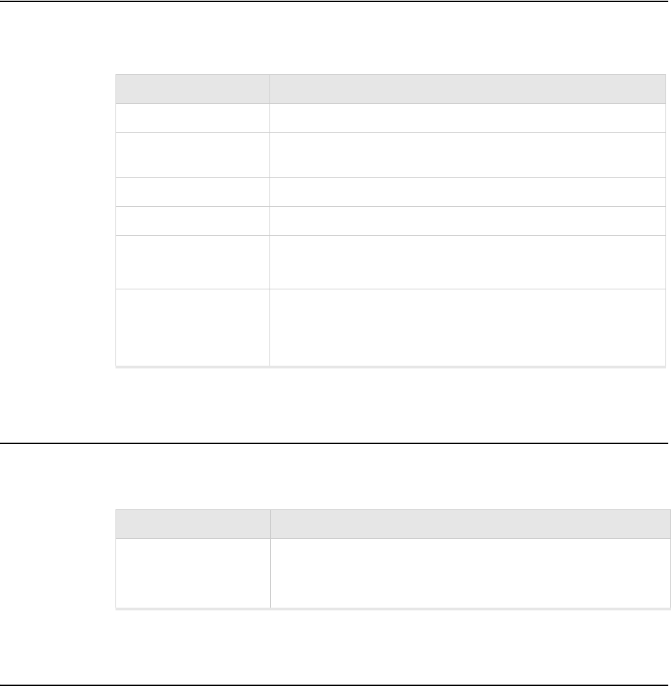
112 Meru Radio Switch RS4000 Reference Guide
Wireless Interface
Wireless Interface
Table 7: 802.11abg Wireless Interface Specifications
Ethernet Interface
Physical
Physical specifications for the Meru RS4000 are provided in the Radio Switch Data Sheet. Contact
your Meru sales engineer for a copy of the document.
Feature Details
Wireless Standards z802.11a, 802.11b, 802.11g
Antennas zTwo external antennas. Omnidirectional and directional antennas for
specific coverage requirements
Wireless Medium Access zWiFi Compliant 802.11 MAC standard
Power Management zPower-save mode for clients in both QoS mode and non-QoS mode
Frame Size zPeak frame size of > 2346 bytes
zFragmentation and reassembly of 802.11/Ethernet frames
Client Activities
Supported
zActive scanning and passive scanning
zPre-authentication
zPower-save mode supported
Feature Detail
Wireline Standard zOne 10/100 Mbps Ethernet (IEEE 802.3) interface, supporting half-
duplex and full-duplex modes
zSupports the Power over Ethernet (PoE) IEEE 802.3af standard
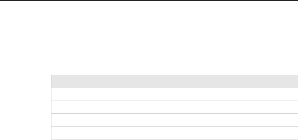
Regulatory Information 113
Appendix D
Regulatory Information
B-1
This appendix has important regulatory compliance information for the following products:
zMulti mode Multi radio Radio Switch—Model RS4000
Please read this appendix first before installing and operating your product, and follow all instructions
provided in the installation chapter. Periodic updates to this document will be posted at
www.merunetworks.com.
This appendix contains the following sections:
zFederal Communications Commission (FCC) Declaration of Conformity (DoC) and Instructions
zList of Regulatory Compliance Certifications Summary by Country
Federal Communications Commission (FCC) Declaration
of Conformity (DoC) and Instructions
Declaration of Conformity
This device is in conformance with Part 15 of the FCC Rules and Regulations for Information
Technology Equipment. Operation of this product is subject to the following two conditions: (1) this
device may not cause harmful interference, and (2) this device must accept any interference received,
including interference that may cause undesired operation.
Company Information
Trade Name Meru
Product Description Multi-mode Multi-radio Radio Switch
Model Nos. RS4000
Responsible Party Meru Networks Inc.

114 Meru Radio Swtich RS4000 Reference Guide
Federal Communications Commission (FCC) Declaration of Conformity (DoC) and Instructions
We, the responsible party, Meru Networks Inc., declare that the above-listed product, Multi-mode
Multi-radio Radio Switch Model No. RS4000, was tested to conform to the applicable FCC Rules
and regulations. The method of testing was in accordance to the most accurate measurement
standards possible, and that all necessary steps have been enforced to assure that all production units
of the same equipment will continue to comply with the Federal Communications Commission’s
requirements.
Issue Date: December 8, 2005
Srinath Sarang
VP, Product Management
Instructions
Warnings
This equipment generates, uses, and can radiate radio frequency energy. If not installed and used in
accordance with the instructions, these products may cause harmful interference to radio
communications. However, there is no guarantee that interference will not occur in a particular
installation. If this equipment does cause harmful interference to radio or television reception, which
can be determined by turning the equipment off and on, the user is encouraged to try and correct the
interference by one or more of the following measures:
1. Reorient or relocate the receiving antenna.
2. Increase the distance between the equipment and the receiver.
3. Connect the equipment to an AC outlet on a circuit different from that to which the receiver is
connected.
4. Consult the dealer or an experienced radio/TV technician for help.
Address 1309 S. Mary Ave.
Sunnyvale, CA 94087
Contact Person/Title Mohammad Sa-id
Senior Regulatory Compliance Manager
Phone - (408) 215-5300
Fax - (408) 215-5301
EUT Certification Summary
Equipment Class Class B
Report References R0510271
Issue Date 11/1/2005
Tested by Bay Area Compliance Lab
Company Information
List of Regulatory Compliance Certifications Summary by Country
Regulatory Information 115
In some situations or environments, the use of wireless devices may be restricted by the proprietor of
the building or responsible representatives of the organization. These situations may, for example,
include the use of wireless equipment on board airplanes, or in any other environment where the risk
of interference to other devices or services is perceived or identified as harmful.
If you are uncertain of the policy that applies on the use of wireless equipment in a specific
organization or environment (such as airports), you are encouraged to ask for authorization to use this
device prior to turning on the equipment.
Caution—Exposure to radio frequency radiation
To comply with the FCC radio frequency exposure requirements, the following antenna installation
and device operating configurations must be satisfied:
zFor client devices using an integral antenna, the separation distance between the antenna(s) and
any person’s body (including hands, wrists, feet and ankles) must be at least 2.5 cm (1 inch).
zFor Base Stations and configurations using an approved external antenna, the separation distance
between the antenna and any person’s body (including hands, wrists, feet and ankles) must be at
least 20 cm (8 inch).
zThe transmitter shall not be collocated with other transmitters or antennas.
Modifications
The FCC requires the user to be notified that any changes or modifications to this device that are not
expressly approved by the manufacturer may void the user’s authority to operate the equipment. The
correction of interference caused by unauthorized modification, substitution or attachment will be the
responsibility of the user. The manufacturer and its authorized resellers or distributors are not liable
for any damage or violation of government regulations that may arise from failing to comply with
these guidelines.
List of Regulatory Compliance Certifications Summary by
Country
Safety approvals—US & Canada In progress
USA/FCC ID RE7-RS4000
116 Meru Radio Swtich RS4000 Reference Guide
List of Regulatory Compliance Certifications Summary by Country
Channels 117
Appendix E
Channels
B-1
This appendix provides the Radio Switch radio channels supported by the world’s regulatory
domains.
This appendix contains the following section:
zChannels
Channels
IEEE 802.11a
The channel identifiers, channel center frequencies, and regulatory domains of each IEEE 802.11a
20-MHz-wide channel are listed in Table 8.
Note:
All channel sets are restricted to indoor usage except the Americas, which allow for indoor
and outdoor use on channels 52 through 64 in the United States.
Table 8: IEEE 802.11a Channels
Channel
Number
Frequency in
MHz
Regulatory Domains
Americas Japan
34 5170 - X
36 5180 X -
38 5190 - X
40 5200 X -

118 Meru Radio Switch RS4000 Reference Guide
Channels
IEEE 802.11bg
The channel identifiers, channel center frequencies, and regulatory domains of each IEEE 802.11bg
22-MHz-wide channel are listed in Table 9.
42 5210 - X
44 5220 X -
46 5230 - X
48 5240 X -
52 5260 X -
56 5280 X -
60 5300 X -
64 5320 X -
149 5745 X -
153 5765 X -
157 5785 X -
161 5805 X -
165 5825 X -
Table 8: IEEE 802.11a Channels (Continued)
Channel
Number
Frequency in
MHz
Regulatory Domains
Americas Japan
Note:
Mexico is included in the Americas regulatory domain; however, channels 1 through 8
are for indoor use only while channels 9 through 11 can be used indoors and outdoors.
Users are responsible for ensuring that the channel set configuration complies with the
regulatory standards of Mexico.

Channels
Channels 119
Table 9: IEEE 802.11bg Channels
Channel
Number
Frequency in
MHz
Regulatory Domains
Americas EMEA Israel China Japan
1 2412 X X - X X
2 2417 X X - X X
3 2422 X X X X X
4 2427 X X X X X
5 2432 X X X X X
6 2437 X X X X X
7 2442 X X X X X
8 2447 X X X X X
9 2452 X X X X X
10 2457 X X - X X
11 2462 X X - X X
12 2467 - X - - X
13 2472 - X - - X
14 2484 - - - - X
(for 802.11b only)
120 Meru Radio Switch RS4000 Reference Guide
Channels
Translated Safety Warnings 121
Appendix F
Translated Safety Warnings
B-1
This appendix provides translations of the safety warnings that appear in this publication. These
translated warnings apply to other documents in which they appear in English. The following safety
warnings appear in this appendix:
zDipole Antenna Installation Warning
zExplosive Device Proximity Warning
zInstallation Warning
zCircuit Breaker (15A) Warning
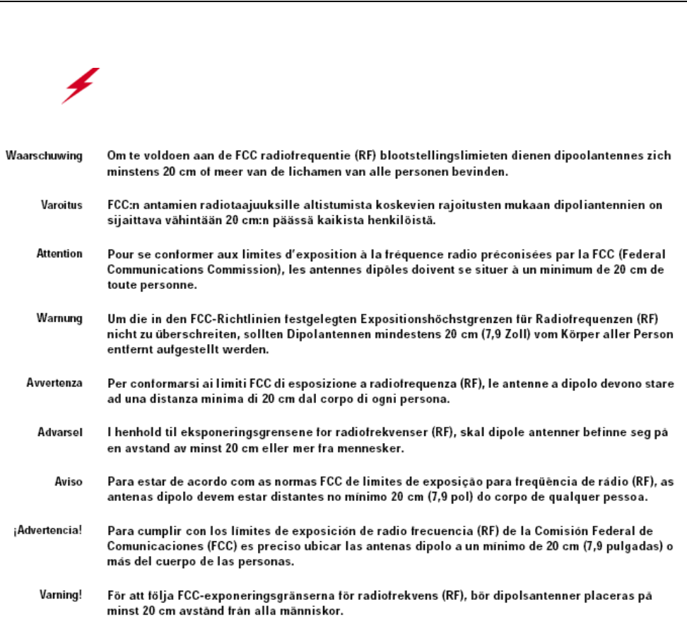
122 Meru Radio Switch RS4000 Reference Guide
Dipole Antenna Installation Warning
Dipole Antenna Installation Warning
Warning!
In order to comply with FCC radio frequency (RF) exposure limits, dipole
antennas should be located at a minimum of 7.9 inches (20 cm) or more from the body of
all persons.
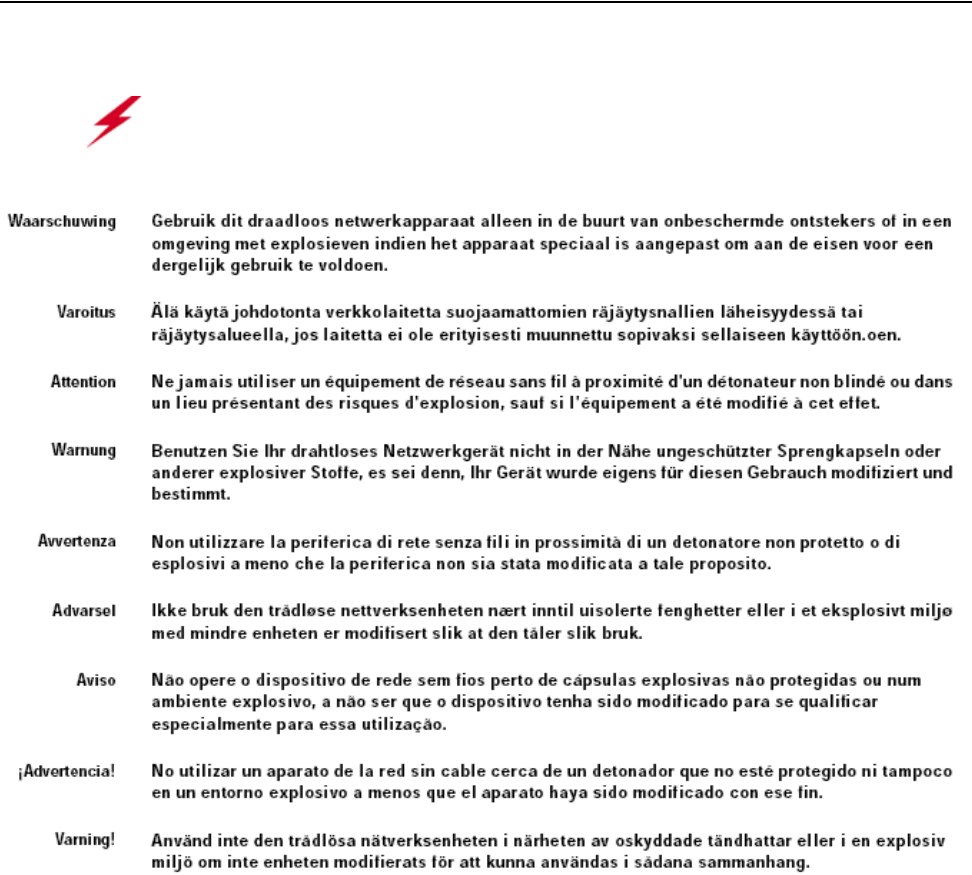
Explosive Device Proximity Warning
Translated Safety Warnings 123
Explosive Device Proximity Warning
Warning!
Do not operate your wireless network device near unshielded blasting caps or
in an explosive environment unless the device has been modified to be especially qualified
for such use.
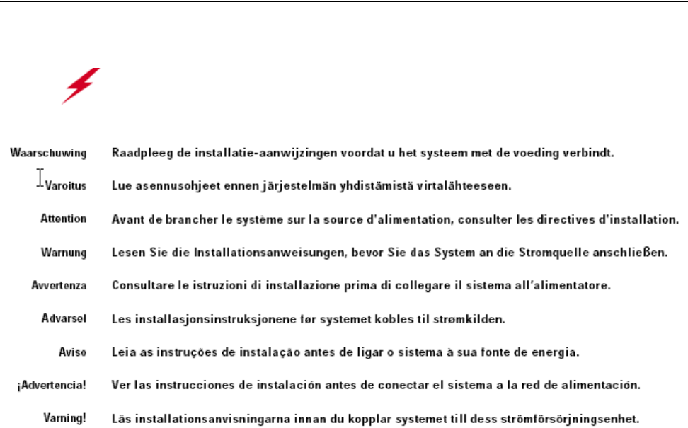
124 Meru Radio Switch RS4000 Reference Guide
Installation Warning
Installation Warning
Warning!
Read the installation instructions before you connect the system to its power
source.
Circuit Breaker (15A) Warning
Translated Safety Warnings 125
Circuit Breaker (15A) Warning
Warning!
This product relies on the building’s installation for short-circuit (overcurrent)
protection. Ensure that a fuse or circuit breaker no larger than 120 VAC, 15A U.S. (240
VAC, 10A international) is used on the phase conductors (all current-carrying conductors).
126 Meru Radio Switch RS4000 Reference Guide
Circuit Breaker (15A) Warning

127
MERU NETWORKS, INC.
Limited Product Warranty
This Limited Product Warranty applies to the original end-user customer of the Meru product which you purchased for your
own use, and not for resale (“Product”), from Meru Networks, Inc. (“Meru”) or its authorized reseller (“Reseller”).
Limited Warranties
—One-year limited hardware warranty: Meru warrants to you that Meru hardware (other than Third Party Products as
described below) will be free from defects in materials and workmanship for a one-year period after the date of delivery
of the applicable product to you from Meru or its Reseller (the “Hardware Warranty Period”). If Meru receives written
notice from you of such defects during the Hardware Warranty Period, Meru will, at its option, either repair or replace
Meru hardware that Meru determines to be defective. Replacement products may be remanufactured units, and will be
warranted for the remainder of the original Hardware Warranty Period, or if greater, for thirty days from delivery of such
replacement. Should Meru be unable to repair or replace the Meru hardware, Meru (or its Reseller, as applicable) will
refund to you the purchase price of the Product.
—90-Day Limited Software Warranty: Meru warrants to you that, for a 90-day period after the date of delivery of the
applicable product to you from Meru or its Reseller (the “Software Warranty Period”), when properly installed and used,
(a) the media on which the Meru software is provided will be free from defects in materials or workmanship; and (b)
the Meru software will substantially conform to the functional specifications in the applicable documentation. If Meru
receives written notice from you of a breach of this warranty during the Software Warranty Period and is able to repro-
duce the defect, Meru will, at its option, either repair or replace the defective Meru software. Should Meru be unable
to repair or replace the Meru software, Meru (or its Reseller, as applicable) will refund to you the purchase price of the
Product.
Exclusions
The warranty on the Product shall not apply to defects resulting from the following:
—Alteration or modification of the Product in any way, including without limitation configuration with software or
components other than those supplied by Meru or integration with parts other than those supplied by Meru.
—Abuse, damage or otherwise being subjected to problems caused by negligence or misapplication (including without
limitation improper or inadequate maintenance or calibration), relocation of the products (including without limitation
damage caused by use of other than Meru shipping containers), or use of the products other than as specified in the appli-
cable Meru product documentation (including without limitation incompatible operating environments and systems), or
improper site preparation or maintenance.
—Damage as a result of accidents, extreme power surge, extreme electromagnetic field, acts of nature or other causes
beyond the control of Meru.
—Use of the Product with software, interfacing, parts or supplies not supplied by Meru.
The warranty on the Product does not apply if the Product is sold, or in the case of software, licensed, for free for evaluation
or demonstration purposes.
Meru expressly disclaims any warranty or obligation to support the Product for all operating environments – for example, as
illustration and not limitation, Meru does not warrant or ensure interoperability of the Product with future telecommunication
systems or other future software or hardware.
You understand and acknowledge that the Products may generate, use or radiate radio frequency energy and may interfere with
radio communications and/or radio and television receptions if is not used and/or installed in accordance with the
documentation for such products. WHILE MERU USES COMMERCIALLY REASONABLE EFFORTS TO ENSURE
COMPLIANCE OF THE PRODUCTS WITH APPLICABLE UNITED STATES FEDERAL COMMUNICATIONS
128 Meru Radio Switch RS4000 Reference Guide
COMMISSION AND PROTECT AGAINST HARMFUL INTERFERENCES, YOU ACKNOWLEDGE AND
AGREE THAT INTERFERENCES WITH RADIO COMMUNICATIONS AND/OR RADIO AND TELEVISION
RECEPTIONS MAY OCCUR AND THAT MERU WILL NOT BE LIABLE FOR ANY DAMAGES OR
INCONVENIENCE BASED ON SUCH INTERFERENCES.
Third Party Products - The above Limited Warranties are exclusive of products manufactured by third parties
(“Third Party Products”). If such third party manufacturer provides a separate warranty with respect to the Third
Party Product, Meru will include such warranty in the packaging of the Meru Product.
Return procedures
To obtain warranty service you must: (a) obtain a return materials authorization number (“RMA#”) from Meru by
contacting support@merunetworks.com, and (b) deliver the Product, in accordance with the instructions provided
by Meru, along with proof of purchase in the form of a copy of the bill of sale including the Product’s serial number,
contact information, RMA# and detailed description of the defect, in either its original package or packaging
providing the Product with a degree of protection equivalent to that of the original packaging, to Meru at the address
below. You agree to obtain adequate insurance to cover loss or damage to the Product during shipment.
If you obtain an RMA# and return the defective Product as described above, Meru will pay the cost of returning the
Product to Meru. Otherwise, you agree to bear such cost, and prior to receipt by Meru, you assume risk of any loss
or damage to the Product. Meru is responsible for the cost of return shipment to you if the Meru Product is defective.
Returned products which are found by Meru to be not defective, returned out-of-warranty or otherwise ineligible
for warranty service will be repaired or replaced at Meru’s standard charges and shipped back to you at your
expense.
At Meru’s sole option, Meru may perform repair service on the Product at your facility, and you agree to provide
Meru with all reasonable access to such facility and the Product, as required by Meru. On-site repair service may
be available and is governed by the specific terms of your purchase.
All replaced parts, whether under warranty or not, are the property of Meru.
Warranty limitations
THE WARRANTIES SET FORTH ABOVE ARE EXCLUSIVE AND NO OTHER WARRANTY, WHETHER
WRITTEN OR ORAL, IS EXPRESSED OR IMPLIED BY MERU, TO THE MAXIMUM EXTENT PERMITTED
BY LAW. THERE ARE NO OTHER WARRANTIES RESPECTING THE PRODUCT AND
DOCUMENTATION AND SERVICES PROVIDED UNDER THIS AGREEMENT, INCLUDING WITHOUT
LIMITATION ANY WARRANTY OF DESIGN, MERCHANTABILITY, FITNESS FOR A PARTICULAR
PURPOSE (EVEN IF MERU HAS BEEN INFORMED OF SUCH PURPOSE), TITLE OR AGAINST
INFRINGEMENT OF THIRD PARTY RIGHTS. IF ANY IMPLIED WARRANTY CANNOT BE DISCLAIMED
UNDER APPLICABLE LAW, THEN SUCH IMPLIED WARRANTY SHALL BE LIMITED IN DURATION TO
THE HARDWARE AND SOFTWARE WARRANTY PERIODS DESCRIBED ABOVE.
NO AGENT OF MERU IS AUTHORIZED TO ALTER OR EXCEED THE WARRANTY OBLIGATIONS OF
MERU.
MERU SPECIFICALLY DOES NOT WARRANT THAT THE MERU SOFTWARE WILL BE ERROR FREE OR
OPERATE WITHOUT INTERRUPTION.
129
THE REMEDIES IN THIS LIMITED PRODUCT WARRANTY ARE YOUR SOLE AND EXCLUSIVE REME-
DIES, AND MERU’S SOLE AND EXCLUSIVE LIABILITY, FOR BREACH OF THE HARDWARE OR SOFT-
WARE WARRANTY SET FORTH ABOVE.
Limitations of Liability
You acknowledge and agree that the consideration which you paid to Meru does not include any consideration by
Meru of the risk of consequential, indirect or incidental damages which may arise in connection with your use of,
or inability to use, the Product. THUS, MERU AND ITS RESELLER WILL NOT BE LIABLE FOR ANY
INDIRECT, INCIDENTAL, SPECIAL, PUNITIVE OR CONSEQUENTIAL DAMAGES, INCLUDING
WITHOUT LIMITATION LOST PROFITS, LOST BUSINESS, LOST DATA, LOSS OF USE, OR COST OF
COVER INCURRED BY YOU ARISING OUT OF OR RELATED TO YOUR PURCHASE OR USE OF, OR
INABILITY TO USE, THIS PRODUCT OR THE SERVICES, UNDER ANY THEORY OF LIABILITY,
WHETHER IN AN ACTION IN CONTRACT, STRICT LIABILITY, TORT (INCLUDING NEGLIGENCE) OR
OTHER LEGAL OR EQUITABLE THEORY, EVEN IF MERU OR ITS RESELLER KNEW OR SHOULD HAVE
KNOWN OF THE POSSIBILITY OF SUCH DAMAGES. IN ANY EVENT, THE CUMULATIVE LIABILITY
OF MERU OR ITS RESELLER FOR ALL CLAIMS WHATSOEVER RELATED TO THE PRODUCT OR THE
SERVICE WILL NOT EXCEED THE PRICE YOU PAID FOR THE PRODUCT OR SERVICES GIVING RISE
TO SUCH CLAIMS.
THE LIMITATIONS SET FORTH HEREIN ARE INTENDED TO LIMIT THE LIABILITY OF MERU AND ITS
RESELLERS AND SHALL APPLY NOTWITHSTANDING ANY FAILURE OF ESSENTIAL PURPOSE OF
ANY LIMITED REMEDY.
The jurisdiction applicable to you may not allow the limitations of liability or damages set forth above, in which
case such limitation shall only apply to you to the extent permitted in such jurisdiction.
Additional Information
This Limited Product Warranty shall be governed by and construed in accordance with the laws of the State of
California, U.S.A., exclusive of its conflict of laws principles. The U.N. Convention on Contracts for the
International Sale of Goods shall not apply.
This Limited Product Warranty is the entire and exclusive agreement between you and Meru with respect to its
subject matter, and any modification or waiver of any provision of this statement is not effective unless expressly
set forth in writing by an authorized representative of Meru.
All inquiries or claims made under this Limited Product Warranty must be sent to Meru at the following address:
Meru Networks Inc.,
1309 South Mary Avenue, Sunnyvale, CA 94087, USA
Tel: 408-215-5300
Fax: 408-215-5301
Email: support@merunetworks.com
130 Meru Radio Switch RS4000 Reference Guide

Meru Networks, Inc.
1309 South Mary Avenue
Sunnyvale, CA 94087
408-215-5300
www.merunetworks.com