Mesa Laboratories 90-0143-001 SCHNEIDER TEMPERATURE SENSOR User Manual 1
Freshloc Technologies SCHNEIDER TEMPERATURE SENSOR 1
UserManual.wiki
>
Mesa Laboratories
>
90 0143 001 User Manual
User Manual
Navigation menu
Upload a User Manual
Namespaces
Wiki Guide
HTML
PDF
Info
Views
User Manual
Discussion / Help
Navigation
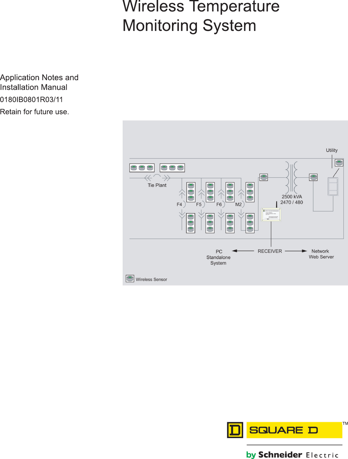
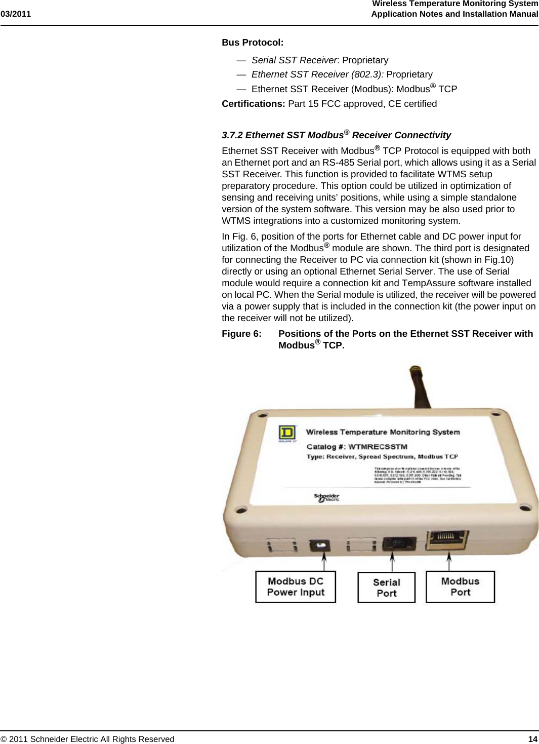
![Wireless Temperature Monitoring System03/2011 Application Notes and Installation Manual© 2011 Schneider Electric All Rights Reserved 6SECTION 3APPLICATION NOTES AND SPECIFICATIONS 3.1. System DescriptionThe Wireless Temperature Monitoring System (WTMS) monitors tempera-tures of the surfaces of energized electrical equipment (see Section 6, Ref [1], Product Specifications 16090-10).The system consists of three components:•Sensors (wireless transmitters)•Receivers (signal receiving units)•Software (processing, alarming and reporting software)Square D High Temperature Sensors are designed to actively measure the temperature of the strategically important points on metal or insulating sur-faces of current carrying parts. The Sensor design allows measuring the tem-perature in wide range, from 0 to 150o C. The Receiver receives the RF signals from the Sensors with temperature, time stamp and identification in-formation from the Sensors and relays this information to PC.Software processes the sensor information and records it into a textual log file. Two versions of software are available: one providing the system working in standalone mode (TempAssure), another in conjunction with power moni-toring system. A version of the Receiver is also available for integration into SCADA and BMS systems.3.2. How WTMS WorksWTMS is quickly and easily installed in any facility by deploying multiple Sen-sors in positions throughout energized equipment to continuously monitor surface temperature. The Sensors transmit a packet every twelve minutes, or, if the temperature is increasing fast, every six minutes.The packet is picked up by a near Receiver/Receiver. Receivers have a typ-ical indoor range of 100 feet with sensors mounted in equipment. The Re-ceiver (antenna) is centrally installed in the control room (a single Receiver can receive information from 100 sensors). However, it is recommended to utilize at least 2 Receivers for a given area to maximize reception of the RF signals from the Sensors.Depending on number of the Sensors in the system and the size of facility, a series of the Receivers can be connected in daisy chain. Once the data is picked up by the Receiver the data is placed on the Receiver network. The Receiver network uses standard category 5 Ethernet Cable to daisy chain the Receivers supplying power and a way to communicate back to the PC. Another option is to transfer the data to PC via multiple ethernet ports.A PC installed at the facility or the existing facility network is used. In standa-lone mode of WTMS the TempAssure Software is installed on local PC and sensing parameters are set (WTMS allows adjusting alert conditions to Cus-tomer specific needs). Temperature information may be reviewed by the Cus-tomer or by Square D Engineering Support (see Section 6, Ref [2], Product Specifications 16090-11- WTMS Consulting Services) via modem or Internet. Alerts or reports can be sent to the customer in numerous ways such as by cell phone, two-way pager, or email. Web monitoring is also an option.](https://usermanual.wiki/Mesa-Laboratories/90-0143-001/User-Guide-1851484-Page-6.png)

![Wireless Temperature Monitoring System03/2011 Application Notes and Installation Manual© 2011 Schneider Electric All Rights Reserved 30SECTION 6 REFERENCES 1. “Technical Specification for Wireless Temperature Monitoring System,” Square D Technical Library, Specification Number: 16090-10 (26 01 20.14). Product Name: Wireless Temperature Monitoring System [On-Line]. Avail-able:http://ecatalog.squared.com/pubs/Electri-cal%20Distribution/26%2001%2020.14.doc2. “Technical Specification for Wireless Temperature Monitoring System - Consulting Services,” Square D Technical Library, Specification Number: 16090-11 (26 01 20.15). Product Name:WTMS - Consulting Services [On-Line]. Available:http://ecatalog.squared.com/pubs/Electrical%20Distribution/26%2001%2020.15.doc SECTION 7 FCC NOTE 1. This device complies with Part 15 of the FCC Rules. Operation is subject to the following two conditions: (1) this device may not cause harmful interference, and (2) this device must accept any interference received, including interference that may cause undesired operation. 2. THE MANUFACTURER IS NOT RESPONSIBLE FOR ANY RADIO OR TV INTERFERENCE CAUSED BY UNAUTHORIZED MODIFICATIONS TO THIS EQUIPMENT. SUCH MODIFICATIONS COULD VOID THE USER'S AUTHORITY TO OPERATE THE EQUIPMENT.](https://usermanual.wiki/Mesa-Laboratories/90-0143-001/User-Guide-1851484-Page-30.png)