Mesa Laboratories 90-0143-001 SCHNEIDER TEMPERATURE SENSOR User Manual 1
Freshloc Technologies SCHNEIDER TEMPERATURE SENSOR 1
User Manual

Application Notes and
Installation Manual
0180IB0801R03/11
Retain for future use.
Wireless Temperature
Monitoring System
TM
HAZARD CATEGORIES AND SPECIAL
SYMBOLS Read these instructions carefully and look at the equipment to become familiar with the
device before trying to install, operate, service or maintain it. The following special
messages may appear throughout this bulletin or on the equipment to warn of potential
hazards or to call attention to information that clarifies or simplifies a procedure.
The addition of either symbol to a “Danger” or “Warning” safety label indicates that an
electrical hazard exists which will result in personal injury if the instructions are not
followed.
This is the safety alert symbol. It is used to alert you to potential personal injury hazards.
Obey all safety messages that follow this symbol to avoid possible injury or death.
PLEASE NOTE Electrical equipment should be installed, operated, serviced, and maintained only by
qualified personnel. No responsibility is assumed by Schneider Electric for any
consequences arising out of the use of this material.
FCC NOTICE This equipment has been tested and found to comply with the limits for a Class A digital
device, pursuant to part 15 of the FCC Rules. These limits are designed to provide
reasonable protection against harmful interference when the equipment generates, uses
and can radiate radio frequency energy and, if not installed and used in accordance with
the instruction manual, may cause harmful interference to radio communications.
Operation of this equipment in a residential area is likely to cause harmful interference in
which case the user will be required to correct the interference at his own expense. This
Class A digital apparatus complies with Canadian ICES-003.
FCC RADIO FREQUENCY
INTERFERENCE STATEMENT This equipment has been tested and found to comply with the limits for a Class B
digital device, pursuant to Part 15 of the FCC Rules. These limits are designed to
provide reasonable protection against harmful interference in a residential
installation. This equipment generates, uses and can radiate radio frequency energy
and, if not installed and used in accordance with the instructions, may cause harmful
interference to radio communications. However, there is no guarantee that
interference will not occur in a particular installation. If this equipment does cause
harmful interference to radio or television reception, which can be determined by
turning the equipment off and on, the user is encouraged to try to correct the
interference by one or more of the following measures:
•Reorient or relocate the receiving antenna;
•Increase the separation between the equipment and receiver;
•Connect the equipment into an outlet on a circuit different from that to which the
receiver is connected.
NOTE: Consult the dealer or an experienced radio/TV technician for help.
DANGER
cDANGER indicates an imminently hazardous situation which, if not
avoided, will result in death or serious injury.
WARNING
WARNING indicates a potentially hazardous situation which, if not
avoided, can result in death or serious injury.
CAUTION
CAUTION, used without the safety alert symbol, indicates a potentially
hazardous situation which, if not avoided, can result in property damage.
Provides additional information to clarify or simplify a procedure.

Wireless Temperature Monitoring System
03/2011 Application Notes and Installation Manual
© 2011 Schneider Electric All Rights Reserved 3
TABLE OF CONTENTS
SECTION 1 SAFETY PRECAUTIONS
SECTION 2 RECEIVING, HANDLING AND STORAGE
SECTION 3 APPLICATION NOTES AND SPECIFICATION
SECTION 4 WTMS INSTALLATION
SECTION 5 VALIDATION TESTS FOR WTMS PARTS AND PERFORMANCE
SECTION 6 REFERENCES
SECTION 7 FCC NOTE

Wireless Temperature Monitoring System
03/2011 Application Notes and Installation Manual
© 2011 Schneider Electric All Rights Reserved 4
SECTION 1
SAFETY PRECAUTIONS In this section:
This section contains important safety precautions that must be followed
before attempting to install, service, or maintain electrical equipment.
Carefully read and follow the safety precautions outlined below
DANGER
HAZARD OF ELECTRIC SHOCK, EXPLOSION, OR ARC FLASH
• The hardware of Wireless Temperature Monitoring System, the
sensors, may be installed only on completely de-energized and
removed out-of-service electrical equipment, such as circuit breakers or
switches. To de-energize apply appropriate personal protective
equipment (PPE) and follow safe electrical work practices. See NFPA
70E
• Only qualified personnel familiar with electrical equipment are to
perform work described in this set of instructions.
• Perform such work only after reading and understanding all of the
instructions contained in this manual.
• The circuit breaker must be in the open (O) position.
• All circuit breaker springs must be discharged.
• Switchgear primary conductors should be grounded.
• Handle this equipment carefully and install, operate and maintain it
correctly in order for it to function properly. Neglecting fundamental
installation and maintenance requirements may lead to personal injury
as well as damage to electrical or other property.
• Carefully inspect your work area and remove any tools and objects left
inside the equipment.
• All instructions in this manual are written with the assumption that the
customer has taken these measures before performing the installation
of wireless sensors inside electrical equipment.
Failure to follow this instruction will result in death or serious injury.

Wireless Temperature Monitoring System
03/2011 Application Notes and Installation Manual
© 2011 Schneider Electric All Rights Reserved 5
SECTION 2
RECEIVING Upon receipt, check the packing list against the equipment received to
ensure the order and shipment are complete. Claims for shortages or errors
must be made in writing to Schneider Electric within 60 days after delivery.
Failure to give such notice will constitute unqualified acceptance and a
waiver of all such claims by the purchaser.
Immediately inspect the equipment for any damage which may have
occurred in transit. If damage is found or suspected, file a claim with the
carrier immediately and notify Schneider Electric. Delivery of equipment to a
carrier at any of the Schneider Electric plants or other shipping points
constitutes delivery to the purchaser regardless of freight payment and title.
All risk of loss or damage pass to purchaser at that time.
For details concerning claims for equipment shortages and other errors,
refer to Schneider Electric “Terms and Conditions of Sale.”
HANDLING Use care when handling the wireless temperature monitoring hardware.
STORAGE When the parts are not in use keep them in a clean, dry, heated corrosion-
free area where it is protected from damage. When the monitoring system
hardware is stored for prolonged periods, inspect it regularly for overall
condition.

Wireless Temperature Monitoring System
03/2011 Application Notes and Installation Manual
© 2011 Schneider Electric All Rights Reserved 6
SECTION 3
APPLICATION NOTES AND
SPECIFICATIONS 3.1. System Description
The Wireless Temperature Monitoring System (WTMS) monitors tempera-
tures of the surfaces of energized electrical equipment (see Section 6, Ref
[1], Product Specifications 16090-10).
The system consists of three components:
•Sensors (wireless transmitters)
•Receivers (signal receiving units)
•Software (processing, alarming and reporting software)
Square D High Temperature Sensors are designed to actively measure the
temperature of the strategically important points on metal or insulating sur-
faces of current carrying parts. The Sensor design allows measuring the tem-
perature in wide range, from 0 to 150o C. The Receiver receives the RF
signals from the Sensors with temperature, time stamp and identification in-
formation from the Sensors and relays this information to PC.
Software processes the sensor information and records it into a textual log
file. Two versions of software are available: one providing the system working
in standalone mode (TempAssure), another in conjunction with power moni-
toring system. A version of the Receiver is also available for integration into
SCADA and BMS systems.
3.2. How WTMS Works
WTMS is quickly and easily installed in any facility by deploying multiple Sen-
sors in positions throughout energized equipment to continuously monitor
surface temperature. The Sensors transmit a packet every twelve minutes,
or, if the temperature is increasing fast, every six minutes.
The packet is picked up by a near Receiver/Receiver. Receivers have a typ-
ical indoor range of 100 feet with sensors mounted in equipment. The Re-
ceiver (antenna) is centrally installed in the control room (a single Receiver
can receive information from 100 sensors). However, it is recommended to
utilize at least 2 Receivers for a given area to maximize reception of the RF
signals from the Sensors.
Depending on number of the Sensors in the system and the size of facility, a
series of the Receivers can be connected in daisy chain. Once the data is
picked up by the Receiver the data is placed on the Receiver network. The
Receiver network uses standard category 5 Ethernet Cable to daisy chain
the Receivers supplying power and a way to communicate back to the PC.
Another option is to transfer the data to PC via multiple ethernet ports.
A PC installed at the facility or the existing facility network is used. In standa-
lone mode of WTMS the TempAssure Software is installed on local PC and
sensing parameters are set (WTMS allows adjusting alert conditions to Cus-
tomer specific needs). Temperature information may be reviewed by the Cus-
tomer or by Square D Engineering Support (see Section 6, Ref [2], Product
Specifications 16090-11- WTMS Consulting Services) via modem or Internet.
Alerts or reports can be sent to the customer in numerous ways such as by
cell phone, two-way pager, or email. Web monitoring is also an option.
Wireless Temperature Monitoring System
03/2011 Application Notes and Installation Manual
© 2011 Schneider Electric All Rights Reserved 7
3.3. System Features
Easy Installation - Installation of software and Receiver is simple. Affix the
receiver to conduit or strut and provide power. The software is also easy to
install.
Monitoring - Software allows monitoring of the temperature readings from
all active Sensors.
Range - Antenna receives Sensor signals up to 100 feet (30 meters) away
(tested successfully up to 1000 ft.).
Population - The system can monitor an unlimited number of Sensors with-
out interfering with one another or loss of identification.
Supervision - Sensors transmit a signal every 6-12 minutes depending of
thermal condition, so you can respond quickly to any problems.
3.4. Square D High Temp Sensors Features
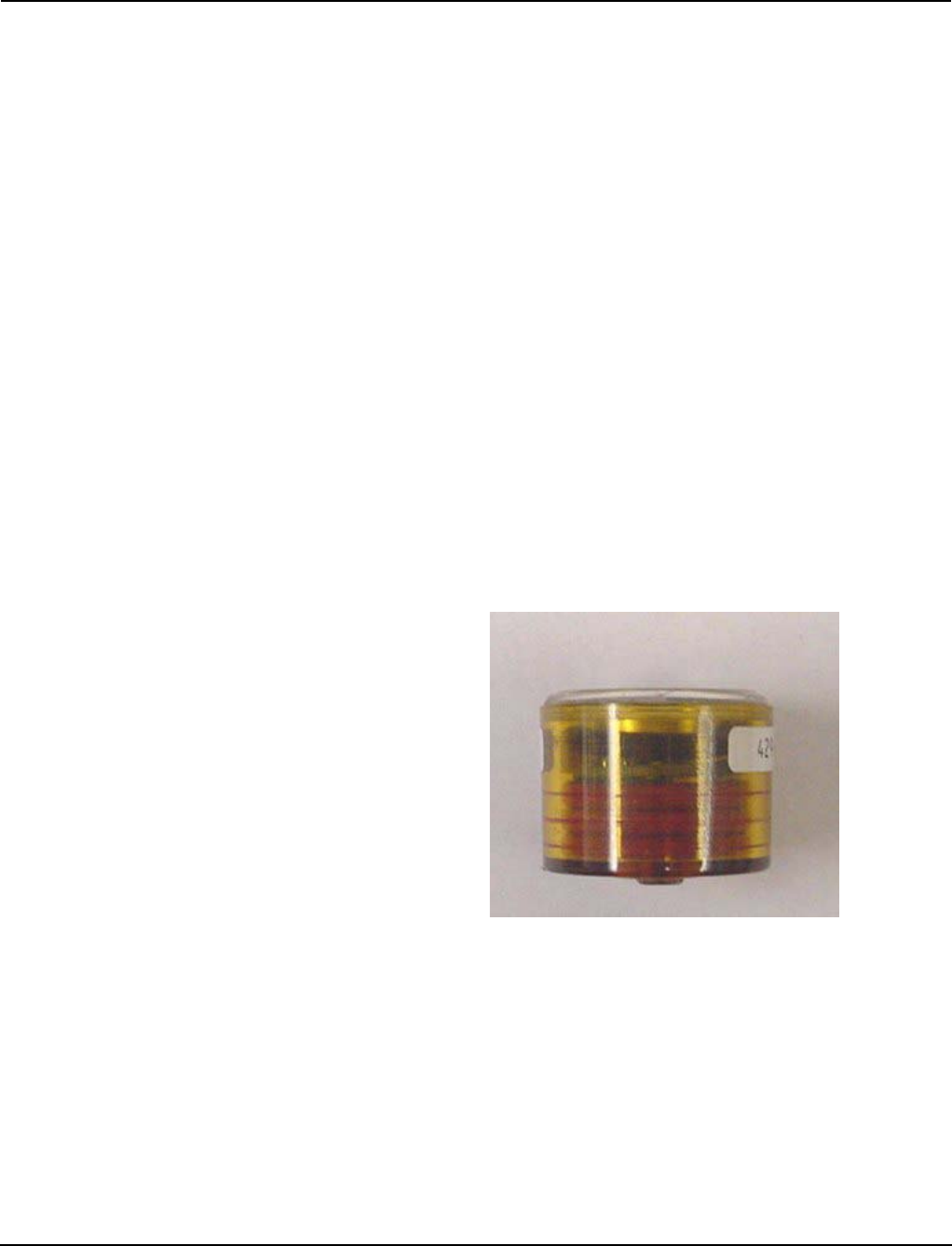
The Sensors are all-in-one temperature sensors and identification tags (Fig
1). The Sensors detect ambient temperature and continuously send radio fre-
quency information to the Receiver. The device transmits the information it
has collected using a low power RF transmission. The Sensors are calibrated
accordingly to application to give accurate temperature readings. Re-calibra-
tion is not required.
Figure 1: Wireless Square D High Temperature Sensor
Low Cost Installation - The Sensors are wireless and can be placed almost
anywhere by using a high temperature adhesive.
Operation - In direct contact with the surface.
Long Battery Life - Sensors utilize a High Temperature 3V lithium battery
that lasts up to 5 years.

Wireless Temperature Monitoring System
03/2011 Application Notes and Installation Manual
© 2011 Schneider Electric All Rights Reserved 8
3.4.1 Application Sensors
Wireless sensors can be applied to any type of new or used LV and MV elec-
trical equipment such as switchgear, circuit breakers, capacitor banks, trans-
formers, motors, busways and cables. The Sensors can be also used on HV
and EHV electrical equipment.
The Sensors can be applied for measuring temperature of any strategically
important points inside energized apparatus, such as stationary contacts, fin-
ger clusters, stabs, bolted connections, as well as any other important loca-
tions where temperature should be controlled. The number of points to
monitor inside the unit is not limited. It is considered important to install the
Sensors on each phase of the apparatus both on load and line side. Some-
times it is possible to detect a problem based on lesser number of the Sen-
sors, for example only on load side, but this decision should be made based
on design and application features. The only limitation is applying the Sen-
sors would be the dimension of the space available at the point of interest,
which should be not less than 1.5 x 1.5 x 1.5 inch3 (4 x 4 x 4 cm3). The Sen-
sors can be attached to either metallic or insulating surfaces and in any po-
sition using installation technique and adhesives recommended in section
4.1.1.
Examples of Sensor installation points are shown in Fig. 2 for LV and MV cir-
cuit breakers. Fig. 3 and Fig. 4 show positions of the Sensors on the bus
stabs and cable connections inside LV switchgear, and MV switchgear, as
well as suggested positions of the sensors for measuring temperature of am-
bient air inside the cells.

Wireless Temperature Monitoring System
03/2011 Application Notes and Installation Manual
© 2011 Schneider Electric All Rights Reserved 9
Figure 2: Wireless temperatures sensors on finger clusters of LV
and MV Circuit Breakers.

Wireless Temperature Monitoring System
03/2011 Application Notes and Installation Manual
© 2011 Schneider Electric All Rights Reserved 10
Figure 3: Wireless temperature sensors on buses and bolted cable
connections inside LV switchgear.

Wireless Temperature Monitoring System
03/2011 Application Notes and Installation Manual
© 2011 Schneider Electric All Rights Reserved 11
Figure 4: Wireless temperature sensors on stabs and bolted cable
connections inside MV switchgear.
3.5. Sensor Specifications
Type: Sensor and Radio Frequency Transmitter .
Physical Dimensions: Sensor casing: D=1.5 in. (40 mm), H =1 in. (25 mm)
Weight: < 20 g (0.7oz.)
Enclosure: Non-conductive, High T and UL tested, waterproofed for humid
and corrosive environment
Operating Temperature: Low: 0º C (32º F); High: 150º C (300º F)

Wireless Temperature Monitoring System
03/2011 Application Notes and Installation Manual
© 2011 Schneider Electric All Rights Reserved 12
Transmission Range: 100 ft. (sensors installed in switchgear).
Mounting Location: On flat clean surface using High T adhesive.
Transmission Frequency: Transmittance intervals change based on the
rate of the temperature change: Signal is transmitted by the Sensor every 12
minutes. However, in case of a temperature rise of 3º C per minute the Sen-
sor will transmit every 6 minutes.
Battery: High temperature 3V lithium battery, easily replaceable in the field.
3.6. WTMS Receiver Features
The WTMS monitors all Sensors, actively measuring temperatures in a se-
lected area. The Receiver constantly monitors and listens for transmissions.
The Receiver determines if a signal is valid or if it is noise to be filtered out,
then mark the transmissions with the proper packet and send it via a network
to a computer for processing.
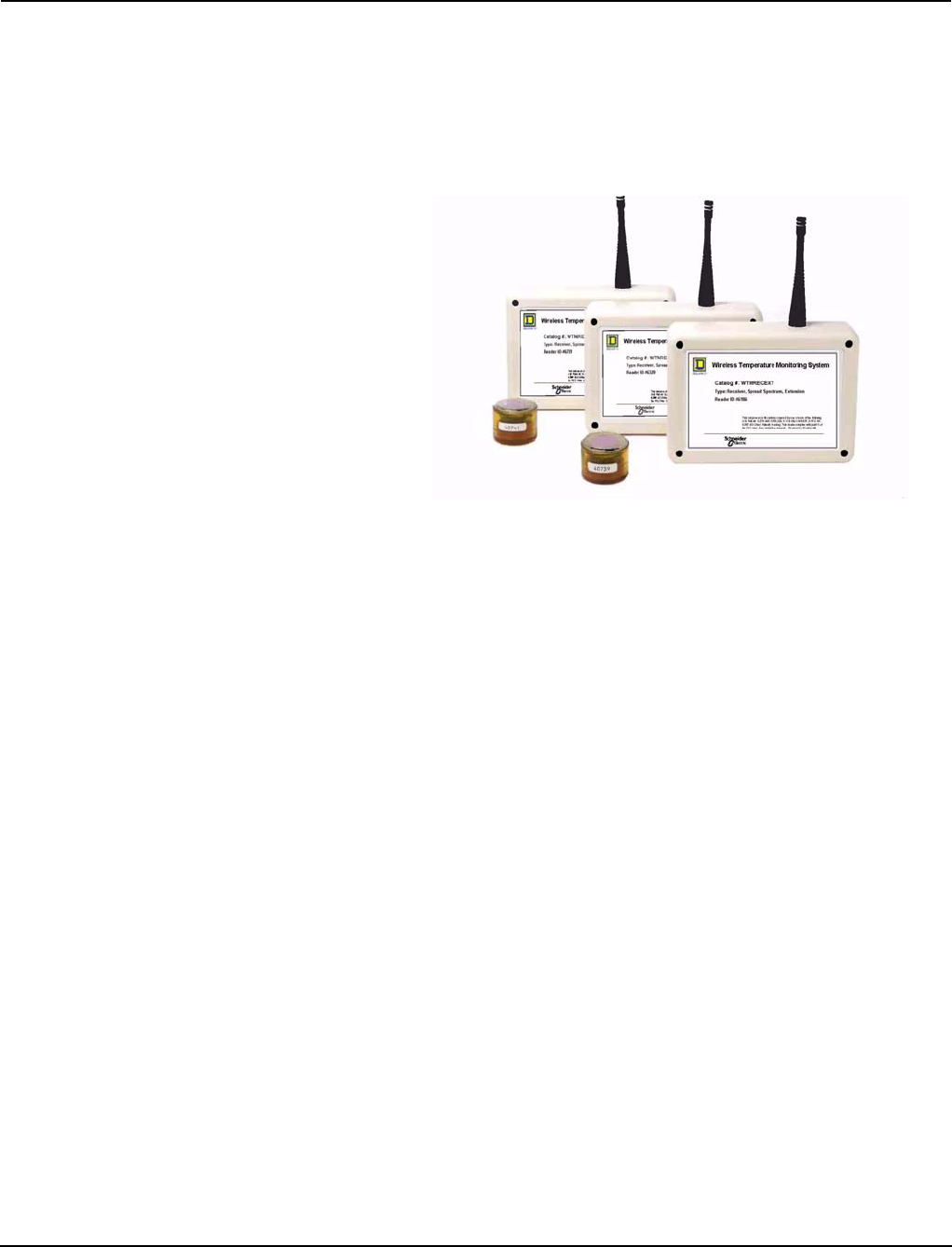
The Receiver utilizes Spread Spectrum Technology (SST). It is available in
three different versions (Fig.5), plus a repeater version.
— Serial SST Receiver receives transmissions and sends them to a PC
via RS-485 using a Connection Kit (RS-485 to RS-232 Converter).
Serial REceivers to be connected, in series, for large coverage
areas.
— SST Receiver with wired Ethernet Connection (802.3).
— Wireless Extension SST Receiver, which provides wireless
transmission of the RF signals to a wired SST Receiver thus
doubling the distance between the transmitters and receiving units.
— Ethernet SST Receiver with Modbus TCP communication protocol.
Power must be supplied to the Receiver by using the power transformer
supplied with the Receiver. For the Serial SST Receiver, another option is to
supply power via the RS--485 network using power from the Connection Kit.
This option is ideal for a Receiver mounted in an area that does not have a
convenient power source.
Wireless Temperature Monitoring System
03/2011 Application Notes and Installation Manual
© 2011 Schneider Electric All Rights Reserved 13
Either the Serial or 802.3 Ethernet type of wired Receiver accepts
temperature and identification information from the Sensors and relays the
information to the TempAssure Software (see section 4.2), which displays
the activity of all wireless Sensors and logs their temperature readings into a
text file for future reference and analysis. A diagnostic screen allows the
user to monitor the system for any problems in the sensory network.
Figure 5: SST Receivers: Serial, Wired Ethernet, and
Wireless/Extension versions.
3.7. Receiver Specifications
3.7.1 SST Receiver Specifications
Type: Spread Spectrum Technology
Frequency Range: 902-928 MHz
Physical Dimensions: 6in. x 4in. x 1.25in. (15cm x 10.2cm x 3.2cm)
Weight: 1/2 lb.
Minimum Reception Range: Omni-directional 300 ft. line-of-site. Range re-
duced by obstructions.
Connection/Communications:
—Serial SST Receiver: RJ-45/RS-485 link to computer. 115,200 baud,
no parity, 8 bits, one stop bit, asynchronous link to computer.
—Ethernet SST Receiver: RJ45 Power (2.1mm)
Power Requirements: 6VDC, 500 mA
Mounting Location: Hanging on a pole, or attached to a flat, clean surface
using adhesive
Operating Temperature: -28ºC to 85ºC (-18ºF to 185ºF)
Accessories: Square D High Temp Sensors.
Bus Adapter Kit: Serial SST Receiver: Connection Kit - RS232 TO RS485
Converter; 7ft. CATS RJ45 Cord; and 485PS - Power Supply
Wireless Temperature Monitoring System
03/2011 Application Notes and Installation Manual
© 2011 Schneider Electric All Rights Reserved 14
Bus Protocol:
—Serial SST Receiver: Proprietary
— Ethernet SST Receiver (802.3): Proprietary
— Ethernet SST Receiver (Modbus): Modbus® TCP
Certifications: Part 15 FCC approved, CE certified
3.7.2 Ethernet SST Modbus® Receiver Connectivity
Ethernet SST Receiver with Modbus® TCP Protocol is equipped with both
an Ethernet port and an RS-485 Serial port, which allows using it as a Serial
SST Receiver. This function is provided to facilitate WTMS setup
preparatory procedure. This option could be utilized in optimization of
sensing and receiving units’ positions, while using a simple standalone
version of the system software. This version may be also used prior to
WTMS integrations into a customized monitoring system.
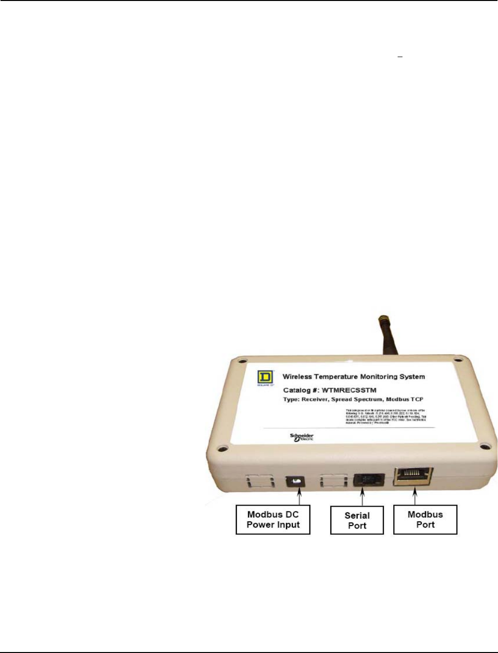
In Fig. 6, position of the ports for Ethernet cable and DC power input for
utilization of the Modbus® module are shown. The third port is designated
for connecting the Receiver to PC via connection kit (shown in Fig.10)
directly or using an optional Ethernet Serial Server. The use of Serial
module would require a connection kit and TempAssure software installed
on local PC. When the Serial module is utilized, the receiver will be powered
via a power supply that is included in the connection kit (the power input on
the receiver will not be utilized).
Figure 6: Positions of the Ports on the Ethernet SST Receiver with
Modbus® TCP.

Wireless Temperature Monitoring System
03/2011 Application Notes and Installation Manual
© 2011 Schneider Electric All Rights Reserved 15
.
SECTION 4
WTMS INSTALLATION 4.1. Installation of Temperature Monitoring Hardware
Hardware of Wireless Temperature Monitoring System consists of the set of
temperature monitoring devices (wireless temperature sensors), signal re-
ceiving devices (Receivers) and connecting kit for connecting the Receiver
to PC and supplying power to the Receiver.
4.1.1. Installation of the Sensors
Use the following procedure to attach wireless Sensor to the part for which
the temperature is to be measured. The Sensor can be installed on any flat
surface made of metallic materials. The Sensor cannot be installed on any
movable contacts or lubricated areas.
Surface preparation note: If Sensors are installed on metallic surfaces on
current carrying part, on insulation, or on compartment doors, the surface
should be cleaned from any dust, particulate matter and moisture with a
clean dry cloth. If needed, use a mild cleaner to remove grease or dirt from
the surface.
Adhesives:
1. RTV Silicone Adhesive (requires about 24 hours curing at room
temperature), such as GE Silicone II Premium Waterproof Silicone,
stock number GE500 90642.
2. Instant adhesive (“super glue”) should hold the sensor in place long
enough for the silicon to cure. It is rated for about 125ºC (~260º F), so
CAUTION
HAZARD OF EQUIPMENT DAMAGE
• Wireless Temperature Monitoring for use with Low Voltage and Medium
Voltage electrical equipment.
Failure to follow this instruction can result in equipment damage and
void the warranty.
DANGER
HAZARD OF ELECTRIC SHOCK, EXPLOSION OR ARC FLASH
• Install and remove Wireless Sensors only on de-energized equipment
and removed out of service electrical equipment. To remove or take out
of service any circuit breaker or switch refer to OEM manual for these
devices.
• To de-energize electrical equipment apply appropriate personal
protective equipment (PPE) and follow safe work practices. See NFPA
70E.
Failure to follow to follow these instructions will result in death or
serious injury

Wireless Temperature Monitoring System
03/2011 Application Notes and Installation Manual
© 2011 Schneider Electric All Rights Reserved 16
the bus bar should be kept below this temperature during the curing
process.
The application procedure should be as follows:
Different views of the sensor are shown in Fig.7. It is pictured from the top
(left) and from the bottom (right), and the sensor case is shown in the
center. For installation, the units should be disassembled by removing the
lid and the sensor assembly (Fig.7) from the case. The case should be
glued onto the equipment surface with the bottom facing the surface. After
the sensor case is attached to the surface, the sensor assembly should be
inserted into the case with the copper enclosure getting into the opening in
the case bottom and the lid should be snapped in to close the case.
1. Apply a ring of silicone in the area between the outer edge of the small
elevated ring located at the opening in the case center and the edge of
case. The silicone ring should be about 2.5mm wide, enough to seep
around the case outside edges when applied (Fig.8, left)
2. Apply four drops of “super glue” equidistantly on the surface of small
elevated ring in the center to the case (Fig.8, right). As soon as the case
is pressed to the surface, the glue will spread and cover ~100% of the
ring surface area.
3. Attach the case bottom in the position on the surface of the part for
which the temperature is to be measured as soon as possible to avoid
an early hardening of the instant glue. Press the sensor to the surface
for 2 minutes, after which it is safe to leave the case for the next 24
hours to let the silicone cure. Super glue is strong enough to hold the
weight of the sensor in any position.
4. Make sure the silicone seeps around the edge of the sensor to prevent
airflow. After the cure is complete, the RTV silicone adhesive takes over.
Figure 7: The sensor: the top of the sensor with RFID label seen through the transparent lid and the label attached to
the side of the case (left), the empty case of the sensor bottom up (center), the bottom of the assembled
sensor with the sensing element in copper enclosure inserted into the opening in the bottom of the case
(right).

Wireless Temperature Monitoring System
03/2011 Application Notes and Installation Manual
© 2011 Schneider Electric All Rights Reserved 17
Figure 8: Sensor assembly with sensing element within copper
enclosure.
4.1.2. Installation of the Receiver
Finding the best location for the Receivers:
The key factor in a successful install, is finding the best possible location for
the Receiver. The plant walk-through will provide best opportunity to search
for a location based on the sensor array. Place readers in open areas to re-
ceive as many signals as possible. Here are a few guidelines to help when
placing the Receiver:
•Install the Receiver as high as possible
•Position the Receiver in a central location
Place the Receiver as close to the center of the location as possible to
maximize the reception of the antenna. If a central location is unavailable,
look for the best possible sit in relationship to the sensors.
•Keep the Receiver away from Interference.
Figure 9: RTV Adhesive ring on the bottom of the case (left); drops of super glue on the inner elevated ring (right).

Wireless Temperature Monitoring System
03/2011 Application Notes and Installation Manual
© 2011 Schneider Electric All Rights Reserved 18
The receiver is designed to work in noisy environments but it is hindered if
placed near (within 5 feet) the following devices:
— Florescent Lighting Fixtures
— Computers and Monitors
— TV’s and Radios
— Large Metal Objects
— Telephone and Network (Ethernet) equipment
— Other items that may block or absorb RF signals which may cause
blind spots to Receivers, such as thick concrete walls, air-
conditioning units.
Suggested mounting methods for Receivers: the Receivers should be
mounted with a minimum of 1 in. separation from flat surfaces such as walls,
rafters, etc. Steel walls and rafters especially require separation to get good
reception.
4.1. 3. Assembly of Connection Kit (Serial Receiver to PC connection)
Parts in Connection Kit:
1. DB25M-DB9F converter
2. RS-232 to RS-485 B&B converter
3. RJ45-DB25F converter
4. Transformer 120 VAC to 12 VDC
5. RJ45 cable (CAT5)
Assembly of Connection Kit
1. Attach the 9-pin connector of the DB25M-DB9F converter to Com port 1
(9-pin) on the back of the computer. If PC does not have 9-pin port use one
of USB ports with USB to RS-232 DB9 converter (not included).
2. Attach another end of DB25M-DB9F converter to the RS232 side of the
B&B converter. Connect the RJ45-DB25F converter to the RS485 end of the
B&B adapter. Connect the Receiver to RJ45-DB25F converter with RJ45 ca-
ble (use any of two lines on the bottom of the Receiver).
Assembled WTMS is shown in Fig. 10. If PC is located at significant distance
from the Receiver, use as long as needed RJ45 cord to connect the Receiver
to RJ45-DB25F converter. Otherwise use the cable included in the kit.
To energize the Receiver, connect the pin of power supply (transformer 120
VAC to 12 VDC) into the side of the RS485-RS232 converter and plug trans-
former into power jack. As soon as connection is made, the LEDs towards
the bottom of chassis of the Receiver begin flashing signalizing that the unit
receives RF signals from the sensors.

Wireless Temperature Monitoring System
03/2011 Application Notes and Installation Manual
© 2011 Schneider Electric All Rights Reserved 19
4.2. Installation of Software for Standalone WTMS
4.2.1. TempAssure installation
There are two versions of TempAssure Software; one for the Serial Receiver
and one for the Ethernet Receiver. It is installed by using TempAssure Soft-
ware on CD. The installation is supported by Installation Wizard. The soft-
ware and log file will be saved on the PC hard drive in the folder C:/Freshloc.
For technical support on downloading and installation of TempAssure Soft-
ware contact Square D Services Engineering.
After installing TempAssure, open the file tassure.cfg in the Freshlock
folder. In the section of text, starting with minTime=425, make the following
edits:
— At the end of the section, add the line: See TwiceWithin=7200.
— Change the value after “NotSeenDisplay” to 7200.
— change the value after “MustSeeEveryTime” to 7200.
4.2.2. TempAssure Software Setup for Serial Receiver
When TempAssure launches, the window shown in Fig.11 will appear. If the
computer cable is plugged into Com 1 it will show “Serial Port 1”. If you need
to change your com port, click on the Options Tab. You will then see the
screen shown in Fig. 12.
Figure 10: Long Range Connection Kit with Serial Receiver..

Wireless Temperature Monitoring System
03/2011 Application Notes and Installation Manual
© 2011 Schneider Electric All Rights Reserved 20
To change the com port:
(1) Type in the com port number in the box next to “Comm Port,” and press
enter.
(2) Click the box next to “Use on Restart” to place a checkmark.
(3) Click on the X to close TAssure.
(4) Restart TAssure
Receiver(s) Setup. You will now be back at the main TAssure screen
(Stats). A blinking green box (directly under “Stats”) means your Receiver is
connected and working. Once you start seeing numbers under Serial Re-
ceives, you know you are receiving data. Now that you know that everything
is working, click on the Receivers Tab (Fig.13). If the “Auto Adds” is checked
all receiving units will be automatically added.
Figure 11: TempAssure main screen
Figure 12: “Option” Tab
Figure 13: “Receiver Tab”

Wireless Temperature Monitoring System
03/2011 Application Notes and Installation Manual
© 2011 Schneider Electric All Rights Reserved 21
This is where you type in the information for the receiver(s) you have:
(1) In the first box, type in the number (ID) of your receiver or choose one of
it is automatically added.
(2) In the second box, type in a name for your receiver (i.e. control room,
etc.).
(3) Click Save.
(4) Repeat for additional Receivers.
Note: You must type a name for the receiver in order to run Local Reports
(discussed later in this document).
Strobe(s) setup: Click on the Strobes tab (Fig.14).
You will need to input the strobe ID’s on this screen in order to view the tem-
peratures of your strobes.
(1) In the first box, enter in the number of your strobe (RFID) or click on “Auto
Adds.”
(2) The second box “xlate” is a pull down menu, select “O Fahren.”
(3) In the third box “Strobe Name,” enter in exact location the Sensor will be
placed.
(4) In the fourth box “Low”, enter in the low alert temperature in Celsius.
For high temperature application this value may be as high as maximum am-
bient temperature according to electrical standards (40 degree C).
(5) In the fifth box “High”, enter in the high alert temperature in Celsius. For
example, if it is an electrical contact, and you would not want it to go above
100 degree C, then you enter in 100 in this box.
(6) The sixth box is “Delay.” You may enter in a time interval for a sensor to
alert. The value needs to be entered in seconds. For example, if you set a
delay of 0 seconds, and your contact temperature rises up to 100 degree C,
the line with the sensor in this location would turn red on the strobe display
screen, indicating a high alert alarm.
(7) Click “Save.” You should now see your strobes (sensors) on both the
TempAssure strobe window and on the strobe display screen.
Strobe Display utility (Fig. 15) displays which sensors are installed and in
which locations, and all other information chosen in Option Tab, such as Tem-
peratures in Fahrenheit or Celsius degree, average temperatures for 15 or
60 minutes, the time stamp of last measurements, and so on.
Figure 14: “Strobe” Tab

Wireless Temperature Monitoring System
03/2011 Application Notes and Installation Manual
© 2011 Schneider Electric All Rights Reserved 22
4.2.3 TempAssure Software Setup for Ethernet 802.3 Receiver
There is a specific version of TempAsure for the Ethernet Receiver. First,
you will need to run the Digi Device Discovery program to configure the
Ethernet Receiver to point to your TempAssure application. Lastly refer to
section 4.2.2. for the remainder of the setup, as most information still
applies to the Ethernet version.
4.2.4 TempAssure Reporting Software
The data from temperature monitoring system is transferred from the sensors
via the Receiver to TempAssure database. Standalone WTM System is work-
ing with TempAssure Software. The data collected by WTMS may be view
and analyzed using TAssure Local Report Program. LocalRpt is a reporting
tool used with the TAssure program to print a report and graph changes in
strobe temperature. LocalRpt also supports graphing of multiple Strobes for
easy comparisons between strobes. The Local Report requires that Sensors
and Receivers have names. Make sure that this has been done before start-
ing Local Report. The first step in using the reporting program is to select the
sensor locations for the report. Click on the Show Item selection button (Fig.
16). This will display a list of sensor locations (items) to choose from. Local-
Rpt automatically selects
all of the items on the list by default. If you don’t want all items included on
the report, click on the Select None button and choose the specific items.
When making your selection you may select multiple strobes by holding
down the Ctrl key and clicking on each item. Then click on the Hide Item Se-
lection Button.
The next step is selecting the time frame for the report (Fig.17). Use the
Date/Time markers to select the starting and ending point. To increase or de-
crease the Date/Time use the arrow buttons next to the Date/Time you wish
to change.
Figure 15: Strobe Display Utility
Figure 16: Local Report: choosing the sensors for display

Wireless Temperature Monitoring System
03/2011 Application Notes and Installation Manual
© 2011 Schneider Electric All Rights Reserved 23
To run a report for an allotted number of days you may click the Days button
and Input a value in the Report for Last ___ Days Blank.
The report is now ready to be created. Select the type of report to use. Select
the List button and LocalRpt will gather a list of strobe entries and display
them in a report format. To create a graph select the Plot button and LocalRpt
will create a line graph from the data recorded in the TAssure.log file. Listed
below are examples of the two types of reports. Shown in Fig. 18 is an exam-
ple of the Plot type report, it creates a graph of the temperature for chosen
strobes.
Figure 17: Local Report: selecting time frame
Figure 18: Local Report Plot

Wireless Temperature Monitoring System
03/2011 Application Notes and Installation Manual
© 2011 Schneider Electric All Rights Reserved 24
The data may be listed if the option “List” is chosen, then the data may be
averaged for any selected time period and presented in tabular format. The
data may be exported into text file, which is easily converted into Excel
format for further analysis.
4.3. SCADA Software Integration
Most Supervisory Control and Data Acquisition (SCADA) and other
monitoring software package have a Modbus driver either “built-in” or
available as an option. In order to connect the Wireless Temperature
monitoring system via Modbus to a software package, the Modbus TCP
WTMS receiver will need to be utilized. The following steps should be
followed to establish communications with the receiver and create a device
tag within the SCADA software.
1. The WTMS receiver will need a static IP address. The unit comes preset
with a default of 192.168.0.100.
a. To configure the IP on the receiver, put your computer on the same
subnet as the receiver (via the IP configuration of your PC).
Important: Write down your settings before making the change.
(Fig.19)
b. Change the IP information on the receiver to work with your network,
by going to the receiver website and clicking “Edit” under network
settings. (See screen capture below) The website is located at
http://<IP address of the reciever>, and can only be reached if your
computer is on the same subnet as the device.
c. Change your PC IP settings back to the original settings you
documented in step (a).
2. The receiver has a range of registers that store the information for each
sensor. The range starts at register 3801 and goes until 19800, with 20
registers allocated to each sensor.
Determine the sensor information that is stored at a specific register range
by going to the Sensor Mapping Page from the link on the main page of the
Figure 19:

Wireless Temperature Monitoring System
03/2011 Application Notes and Installation Manual
© 2011 Schneider Electric All Rights Reserved 25
receiver. The table will only show entries for discovered sensors up to a
maximum of 800 entries.
A sample mapping page is displayed in the screen capture below (Fig.20).
The sensors are assigned a range by the receiver, as it detects them. The
first range of 290 registers is referred to as Table 1, and so forth.
Following is a list of useful quantities and their offsets within the range of
registers assigned to each sensor:
Example:
To read the temperature in Celsius for Sensor ID 42154 displayed in the
above diagram, you would send a ModBus read request to address
157.198.172.61, specifying the 3825 (3821 + 4), as the register number
from which to read.
In the response packet you will get the temperature in hundreths of a
degree Celsius. So if the temperature is 25 degrees Celsius you will get a
ModBus response with the number 2500.
3. Clear the current sensor table by writing one to Modbus address 50000.
This will also clear the flash tables.
4. Acquire sensor channels.
5. When all channels have been acquired (verify the sensor mapping as
described in Step 2), write the sensor directory to flash by writing the
value “2” to Modbus address 50001.
NOTE: the flash write operation could take up to a minute depending on
the number of channels acquired, so leave the unit powered up.
Figure 20:
Quantity Offset
Sensor ID (two registers) 1 and 2
Celsius Reading in Hundredths of degree C 4
Fahrenheit Reading in Hundredths of degree F 14

Wireless Temperature Monitoring System
03/2011 Application Notes and Installation Manual
© 2011 Schneider Electric All Rights Reserved 26
6. Setup the Modbus application to reference the sensor table locations
acquired above.
4.4. Modbus Specifications for WTMS Modbus TCP Receiver
A. Configuration - The TCP/IP Address, Subnet Mask and Default Gateway
Address can all be addressed over the Modbus TCP network starting at
Modbus location 60,000 for 12 registers. Each octet is a separate word.
These parameters can also be configured via the configuration web
page located at http://192.168.0.100/index.htm. The web page also
allows an application name to be programmed into the device.
B. A maximum of 800 Sensor ID packets (Sensor ID/Channel) can be
addresses through the Modbus Server Interface at device id1. Only
sensor packets starting with 0x02 0x01 are decoded; all others are
ignored
C. Modbus TCP Data Space Mapping
Table 1:
Modbus Address Holding
Register
1- 2 Sensor ID for table 1
3 Channel # for table 1
4 Reserved
5 - 6 Sensor ID for table 2
7 Channel # for table 2
8 Reserved
3113 - 3120 Sensor ID/Channel for table 800
3201 - 3250 Status Bit array
3251 - 3800 Reserved
3801 - 3830 Sensor Data Packet (table 800)
50000 (Write 1) Clear Sensor Tables (a write of any value
50001 (Write 2) Write Current Sensor Directory (a write of
any value)
50002 - 50003 (read) Master TIck count - reset when power
cycled
60000 IP Address MSB
60001 IP Address
60002 IP Address
60003 IP Address LSB
60004 Subnet Mask MSB
60005 Subnet Mask
60006 Subnet Mask
60007 Subnet Mask LSB
60008 Gateway Address MSB
60009 Gateway Address
60010 Gateway Address
60011 Gateway Address LSB

Wireless Temperature Monitoring System
03/2011 Application Notes and Installation Manual
© 2011 Schneider Electric All Rights Reserved 27
D. Status Data starting at 3201 is a set of registers that provide packet
arrival status. Each bit of the status data registers maps to a Sensor
ID/channel combination. There are 800 bits (1 per Sensor ID/Channel
Packet) in this structure (50 Modbus words). The bit will be set to a 1 to
indicate that the table entry has data.
Status Bits:
First word of status (3201) 15 14 13 12 11 10 9 8 7 6 5 4 3 2 1 0
table entry 16 ------------------^
table entry 15 ----------------------^
table entry 14 --------------------------^
table entry 1 -------------------------------------------------------------------^
Second word of status (3202) 15 14 13 12 11 10 9 8 7 6 5 4 3 2 1 0
table entry 17 ------------------------------------------------------------------^
E. Sensor Data Packet Mapping (starting at Word 3801)
1. Offset 0: SS Channel
2. Offset 1: Sensor ISD (Two Words)
3. Offset 3: Channel and Type
4. Offset 4: Measurement (Celsius)
5. Offset 5: Reserved
6. Offset 6: Sequence Count
7. Offset 7: Signal Strength
8. Offset 8: Pre-correction
9. Offset 9: Post-correction
10. Offset 10: SSTID (2 Words)
11. Offset 12: Delta Tick Count (2 Words)
12. Offset 14: Measurement (Fahrenheit)
13. Offset 15: Reserved (Four Words)
F. Sensor Data Packets are filled in the order that packets arrive. A Sensor
ID/Channel block is assigned to a Sensor ID when the first packet for
that Sensor ID is received.
G. Diagnostic packets are stored identically to Sensor ID packets.
H. Time Stamping - 100 msec tick count resolution measured from power
on. This tick count is a double word. It resets on power on and rollover.
I. Diagnostics - If the Default Gateway IP Address has a non-zero value,
diagnostic information will be broadcast in a UDP packet on port 45000.
This packet will show the serial data received and the calculated
checksum of the packet.
J. The Sensor Directory mapping will be saved to non-volatile flash
memory when a value of two is written to the Modbus register 50001.
This information will be restored when the Gateway powers up.
K. Temperature decoding - All temperatures for sensors are shown on
Channel 12 and are two byte signed words. The values represent the
temperature measured at the time received by the gateway (minus time
to transmit which is well under 1 second). The measurement is a signed
value in 100ths of a degree centigrade and the range is in excess of
150C.

Wireless Temperature Monitoring System
03/2011 Application Notes and Installation Manual
© 2011 Schneider Electric All Rights Reserved 28
L. Clear Sensor Tables - A write of one to Modbus address 50000 will clear
the stored data tables (and write the directory to flash).
M. Write Sensor Directory - A write of two to Modbus 50001 will write the
stored sensor directory to flash.
SECTION 5
VALIDATION TESTS FOR WTMS PARTS
AND PERFORMANCE Square D Services designed and arranged a set of validation tests at
independent laboratories, and provided required documentation for the tests.
Below is a listing of test providers and description of the tests' goals and re-
sults. Complete reports of all test listed are available upon request.
Testing Providers:
•Square D Services Engineering
•Square D RF Laboratory
•Freshloc Technologies
•Independent Testing Services:
— Met Laboratories
— Underwriters Laboratories
—FCC
— Nemco USA
5.1. Validation Tests provided by Square D Engineering Services
5.1.1. Calibration Technique for Square D High Temp Sensors (direct
thermal contact with the surface)
Square D Engineering developed a new calibration technique providing sen-
sor calibration in the conditions adequate to the system application. All sen-
sors are calibrated within the oven with stabilized ambient temperature with
the sensors installed on the surface of metal bus, which temperature is
changing within the range of T from 0ºC to 150ºC and controlled with TCs.
5.1.2. Testing of Adhesion Quality of Silicone RTV as HT adhesive
Two different properties of high temperature adhesive have been tested to
approve an adhesive for using it for attachment of wireless temperature sen-
sors in energized electrical equipment: (1) chemical inertness at high temper-
atures towards metallic and insulating surfaces, and (2) an ability to hold the
sensors in vertical or upside down position for the period in service. Testing
of Silicon RTV sealant at high temperature proved that the product provides
a good adhesion and is chemically inert towards the surface to which the
sensors may be attached. This adhesive leaves no residue on metal surfaces
of the bus or insulation after the sensors have been removed. Additional test-
ing was provided by Freshloc technologies on Silicone adhesive strength.
The preferred adhesive was placed on a test bus bar and allowed to cure for
24 hours. The bus bar was then heated to approximately 150ºC for two
hours. At the end of two hours, the adhesive was tested to tolerate a load of
up to 20 lbs. The bond strength measure proved that the silicone adhesive is
sufficient to hold the weight of the sensor in vertical or upside down configua-
tions.

Wireless Temperature Monitoring System
03/2011 Application Notes and Installation Manual
© 2011 Schneider Electric All Rights Reserved 29
5.1.3. Influence of High Voltage on Sensors Performance Signal Trans-
mittance Test setup
The measurements have been conducted using HiPot Set providing high
voltage on the metal part using a Step-up VT that allows raising the voltage
up to 100 kV. Step-up VT is a source of corona by itself. Several Square D
High Temp sensors were positioned on piece of copper bus bar, which was
connected to Step-up transformer with the cable. The voltage has been
raised from 5 kV to 50 kV and held for 10 minutes at each voltage. At the last
stage of the test the voltage has been raised to 25 kV and was hold at this
value for one hour. During the test the receiver was in close proximity to the
Step-up transformer at the distance about 5 feet. During the runs with 50 kV
applied to bus bar corona occurred, which produced very strong sound. Mul-
tiple sensors have been located close to energized piece of bus bar to deter-
mine if their functions as well as performance of Receiver are affected by HV
corona.
Test Results
The effect of high Voltage and Corona in close proximity to the wireless sen-
sors has been found insignificant.
5.2. WTMS Validation Tests Provided by Testing Services
The following tests (Table 2) have been provided by Met Laboratories, Un-
derwriters Laboratories in Northbrook, IL and RF Laboratory of Square D in
Raleigh, NC. and Nemco USA, Inc. Test reports are available upon request.
FCC certification report has been received from Freshloc Technologies.
Table 2:
No. Test Standard, Level Test Lab Comments, Results
1UL Test / installation
Category
UL 3111-1, IEC 61010-1,
UL 61010B-1 and IEC/EN1010
Level III
UL Lab
Northbrook Completed, Passed
2Vibration Test IEC61010-1 PMO SEP1001 Met Lab Completed, Passed
3Drop Test PMO SEP 1002 Met Lab Completed, Passed
4EMC Tests FCC Part 15, Class A/CE Heavy
Industrial/Radiated/Conducted FCC Certified
5EMI Tests
IEC 6100-4-4, Level 3; 4-3; 4-3;
4-8 4-2, level 3; 4-5 level 4 Square D RF Lab Completed, Passed
6EMI Tests (European
Standards for CE Mark),
Receivers
ETSI EN 300 220-3 V1.1.1
(2000-09); ETSI EN 301 489-1
V1.4.1 (2002-08); ETSI EN 301
489-17 V1.2.1 (2002-08); IEC
60950-1/EN 60950-1
Nemco USA, Inc. Completed, Passed
7EMI Tests (European
Standards for CE Mark),
Sensors
ETSI EN 301 489-1 V1.4.1
(2002-08); ETSI EN 301 489-17
V1.2.1 (2002-08); IEC 60950-
1/EN 60950-1
Nemco USA, Inc. Completed, Passed

Wireless Temperature Monitoring System
03/2011 Application Notes and Installation Manual
© 2011 Schneider Electric All Rights Reserved 30
SECTION 6
REFERENCES 1. “Technical Specification for Wireless Temperature Monitoring System,”
Square D Technical Library, Specification Number: 16090-10 (26 01 20.14).
Product Name: Wireless Temperature Monitoring System [On-Line]. Avail-
able:
http://ecatalog.squared.com/pubs/Electri-
cal%20Distribution/26%2001%2020.14.doc
2. “Technical Specification for Wireless Temperature Monitoring System -
Consulting Services,” Square D Technical Library, Specification Number:
16090-11 (26 01 20.15). Product Name:
WTMS - Consulting Services [On-Line]. Available:
http://ecatalog.squared.com/pubs/Electrical%20Distribution/26%2001%202
0.15.doc
SECTION 7
FCC NOTE
1. This device complies with Part 15 of the FCC Rules.
Operation is subject to the following two conditions: (1) this device may not cause harmful interference, and (2) this device must
accept any interference received, including interference that may cause undesired operation.
2. THE MANUFACTURER IS NOT RESPONSIBLE FOR ANY RADIO OR TV INTERFERENCE CAUSED BY UNAUTHORIZED
MODIFICATIONS TO THIS EQUIPMENT. SUCH MODIFICATIONS COULD VOID THE USER'S AUTHORITY TO OPERATE
THE EQUIPMENT.