Meteorcomm 54505001-01 Meteor Burst Packet Data Radio For Fixed Or Mobile User Manual Instruction Manual Exhibit 8
Meteorcomm LLC Meteor Burst Packet Data Radio For Fixed Or Mobile Instruction Manual Exhibit 8
UserManual.wiki
>
Meteorcomm
>
54505001 01 User Manual
Instruction Manual Exhibit 8
Navigation menu
Upload a User Manual
Namespaces
Wiki Guide
HTML
PDF
Info
Views
User Manual
Discussion / Help
Navigation


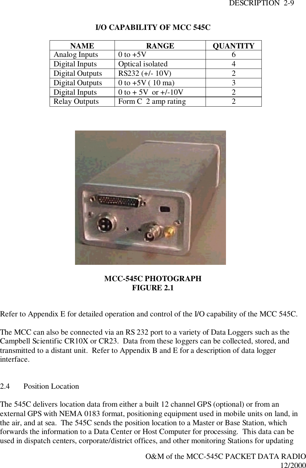
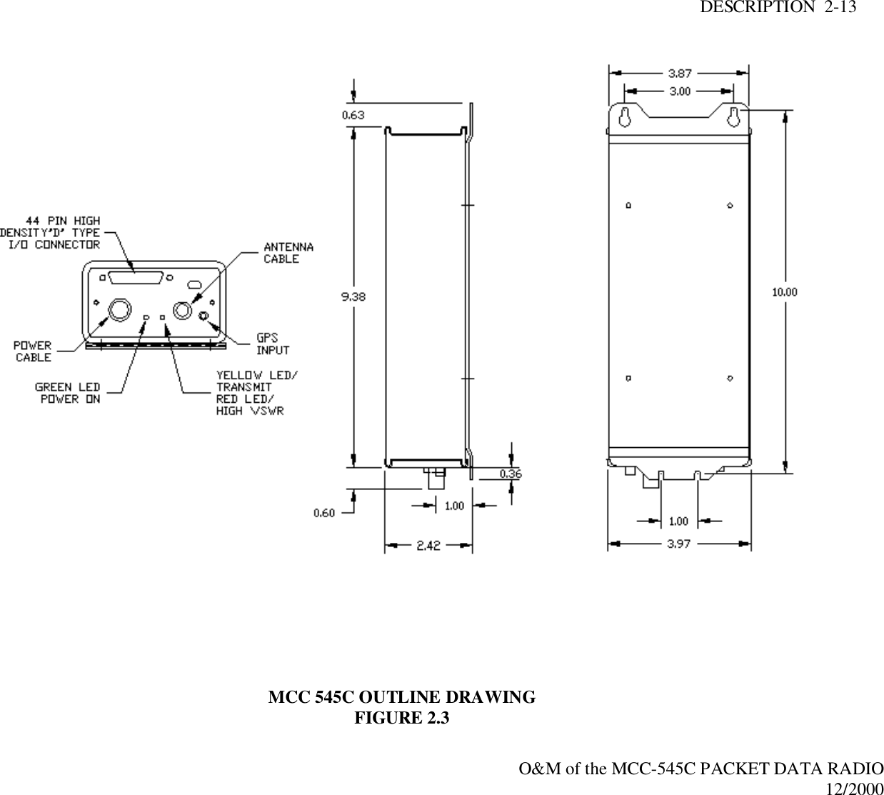
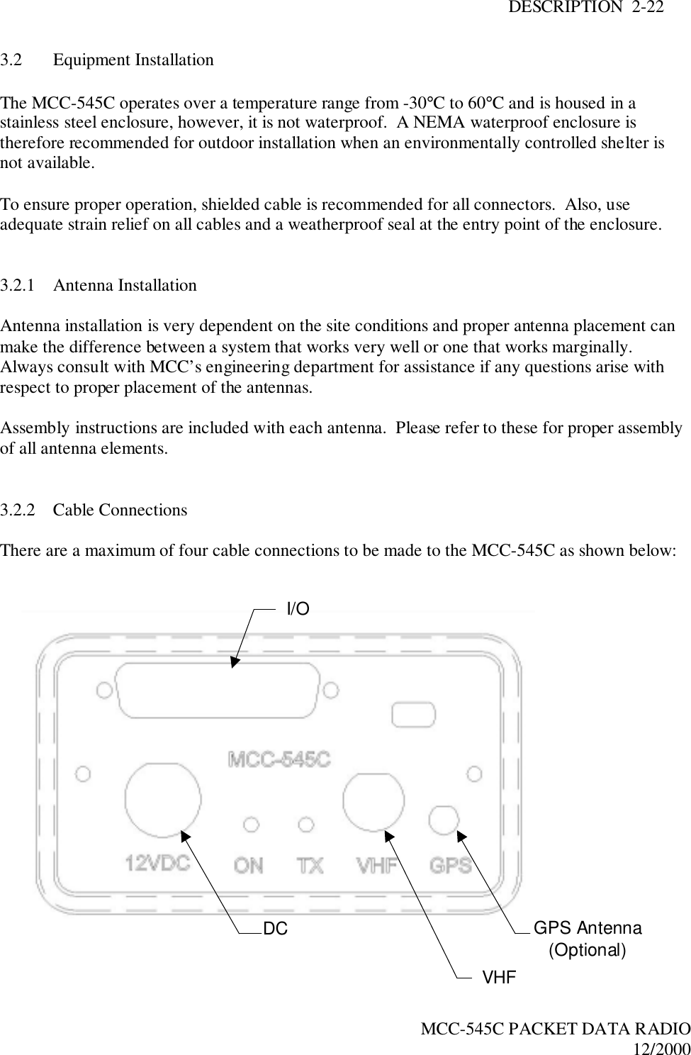
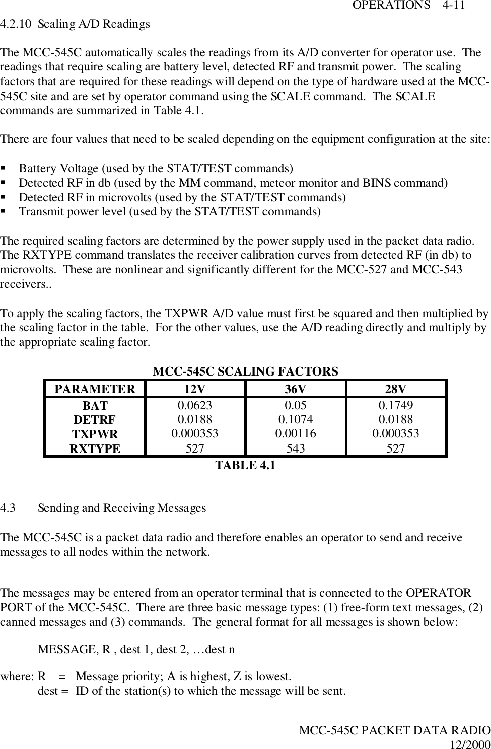
![DESCRIPTION 2-6O&M of the MCC-545C PACKET DATA RADIO12/20001.2 Support DocumentsCustomer Specific System ManualMCC-520B/MCC-520C Operations Manual1.3 ConventionsThe following conventions are used in this manual:Any system-dependent options are indicated with an "*".When presented in the text, user commands and computer printout are boldfaced; e.g., EnterDELETE. Command parameters are presented in lower case; e.g., DEFINE,id. Optionalparameters are enclosed in brackets; e.g., TIME{,hh:mm:ss}Names of terminal keys are capitalized and enclosed in square brackets when mentioned in thetext; e.g., Press [ESC].Names of hardware switches, meters, etc. are capitalized; e.g., PWR ON switch.NOTEUsed for special emphasis of materialIMPORTANTUsed for added emphasis of material.CAUTIONSignals the operator to proceed carefully.WARNING! WARNING! WARNING!Used in cases where failure to heed the message may result in personal injury or equipmentdamage.](https://usermanual.wiki/Meteorcomm/54505001-01/User-Guide-134342-Page-11.png)

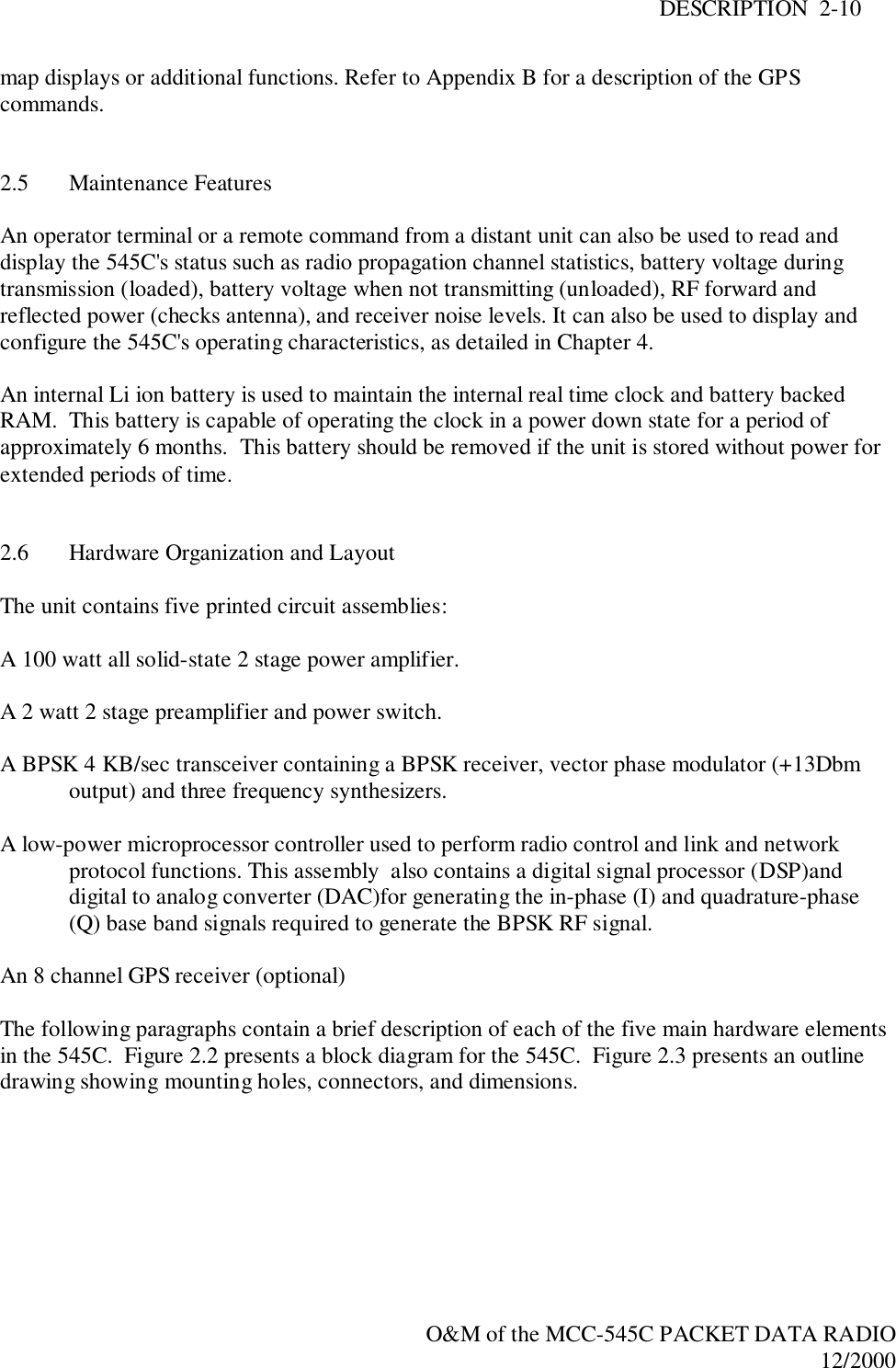

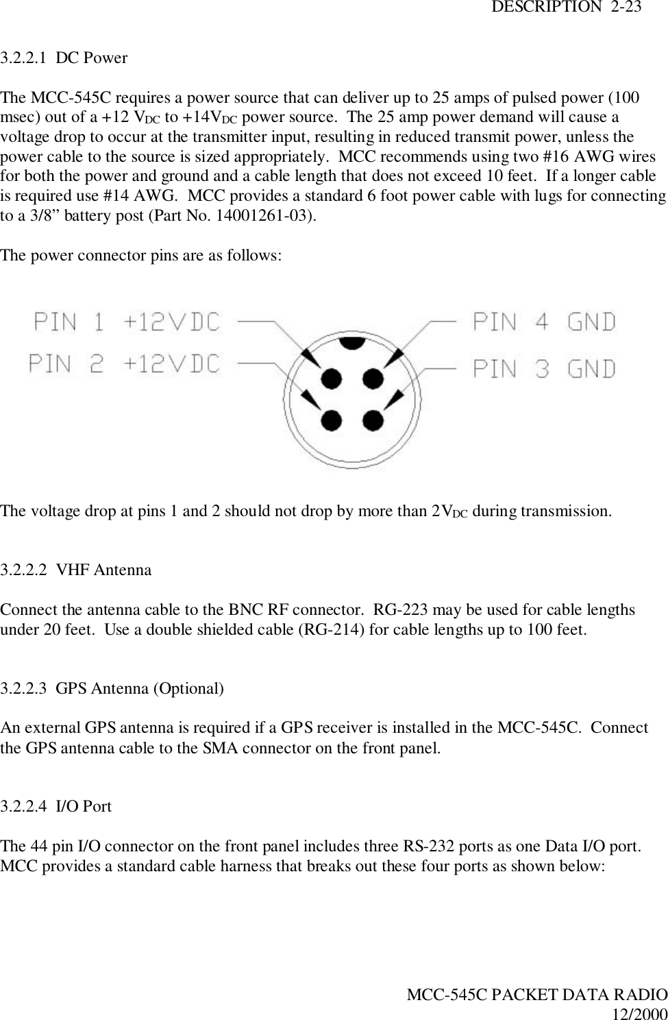
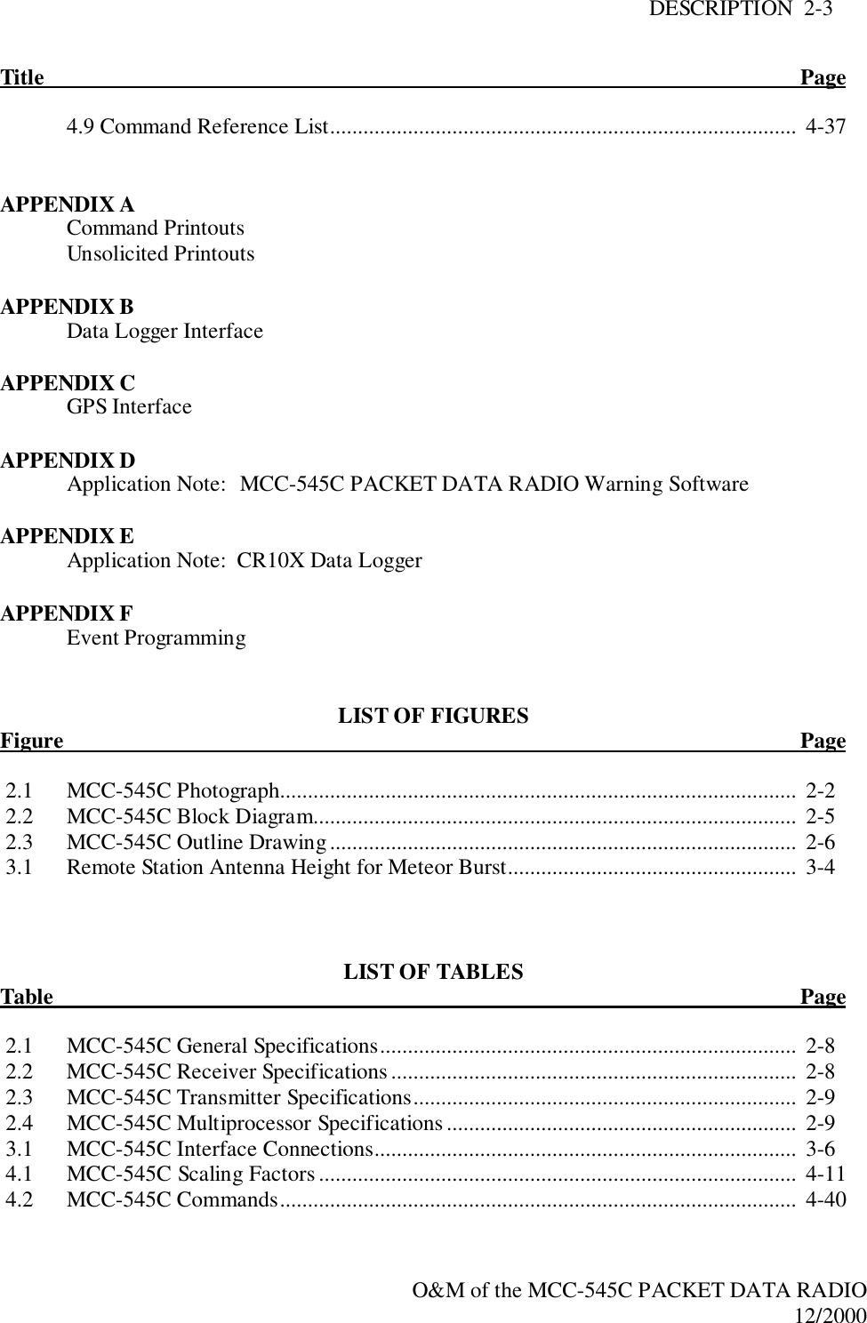
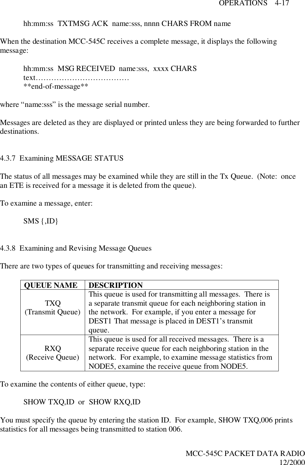
![DESCRIPTION 2-30MCC-545C PACKET DATA RADIO12/20003.3.4 RF TestA very thorough RF test can be made by typing TEST[CR]. TEST causes the processor to turnthe transmitter ON and measures the forward and reverse RF power that is being transmitted. Italso measures the battery voltage under load and the antenna noise voltage.The following response will be displayed on the operator terminal: Syncs Xmits Acks pwr-fwd pwr-rev v-bat det-RFXXXX YYYY ZZZZ AAAA BBBB CCC DDDwhere: XXXX = # of sync patterns received from the master station.YYYY = # of transmissions made by the MCC-545C.ZZZZ = # of Acknowledgements received from master station.AAAA = Forward power in watts. This should be greater than 80 watts.BBBB = Reflected power in watts. This should be less than 5 watts.CCC = Battery voltage under load (while transmitting). This should be greaterthan 10.6 VDC.DDD = Received signal strength in dbm. This will normally be the noise levelat the antenna.Troubleshooting SuggestionsIf the battery voltage is normal, the forward RF power should be at least 80 watts. If it is lowerthan 80 watts check for proper cabling to the power source. (see Section 3.2.2.1).If the reverse RF power is greater than 5 watts check the antenna and coaxial cabling for properinstallation.If both the forward and reverse power are low, the transmitter may be automatically shuttingdown due to an antenna VSWR greater than 3:1. Check the antenna and coaxial cabling forproper installation.This completes the power-up sequence of the MCC-545C. The unit is now ready for operation.Refer to Chapter 4 for detailed operating instructions.](https://usermanual.wiki/Meteorcomm/54505001-01/User-Guide-134342-Page-35.png)

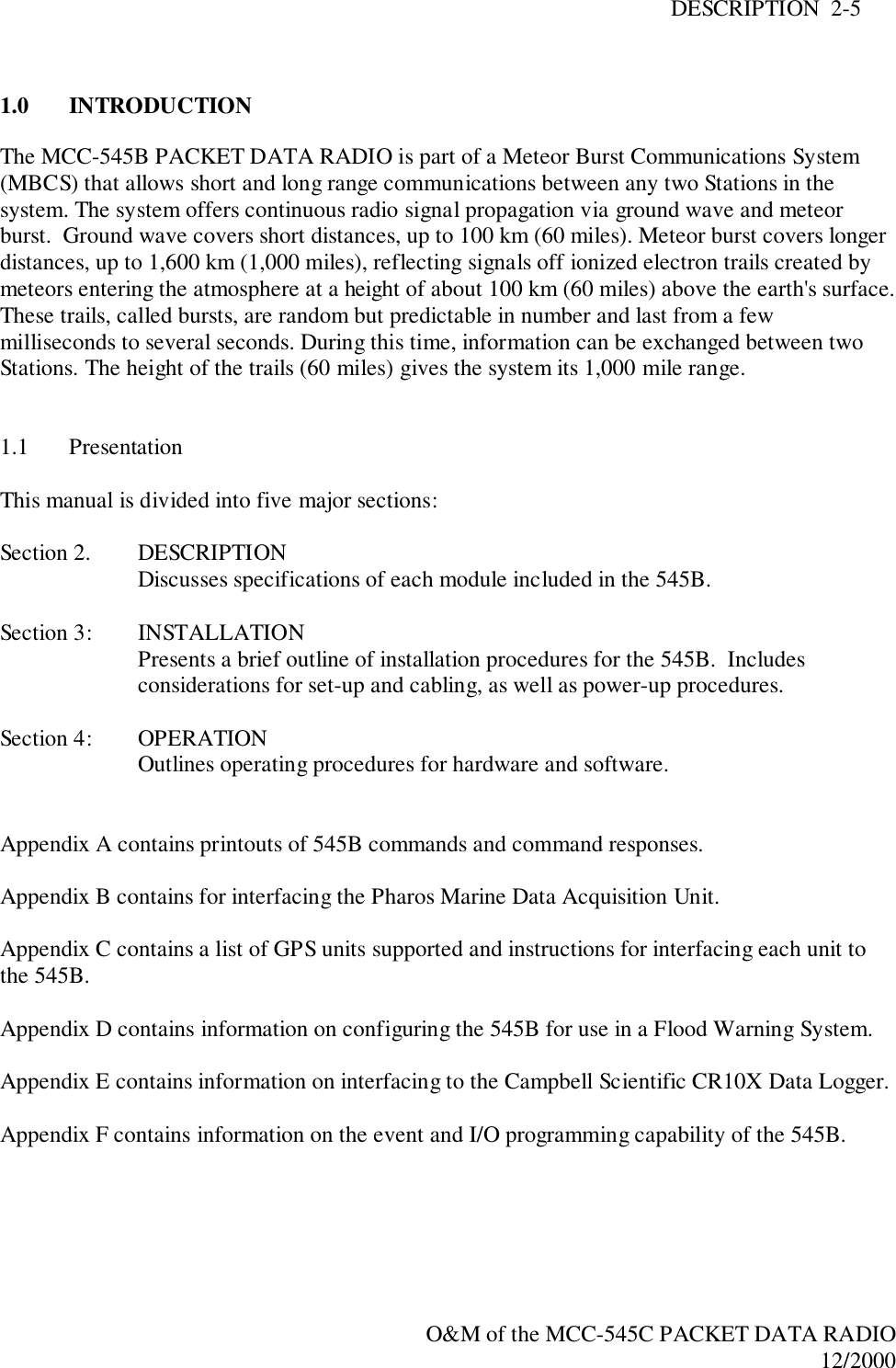
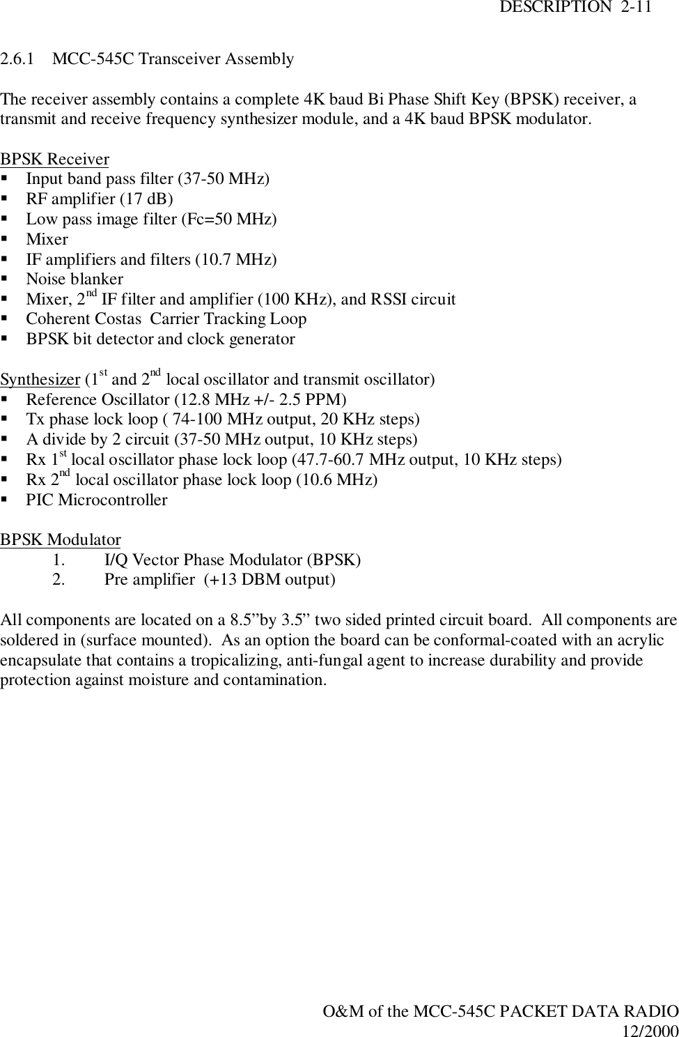
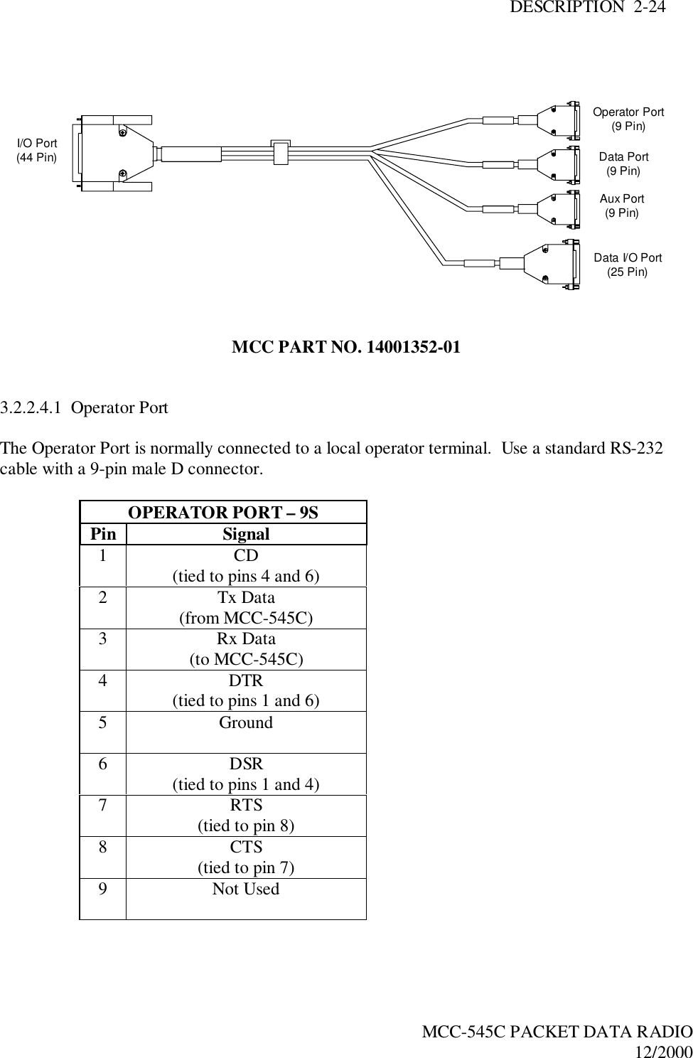
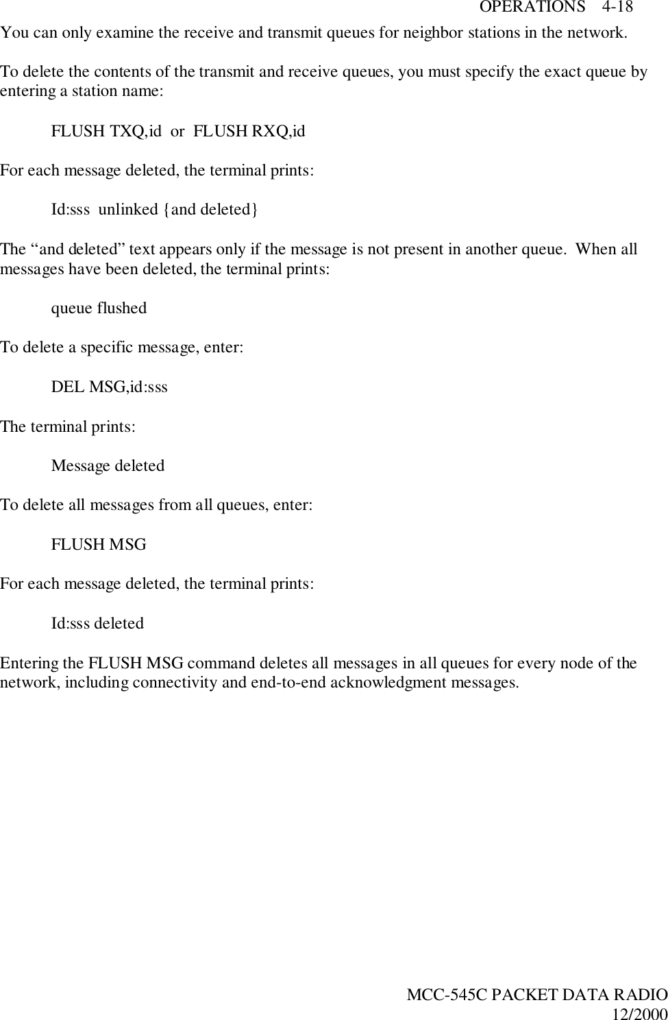
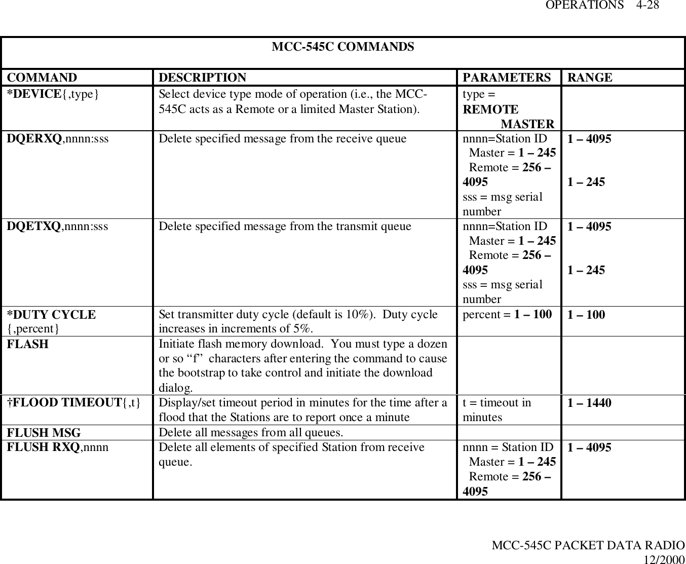
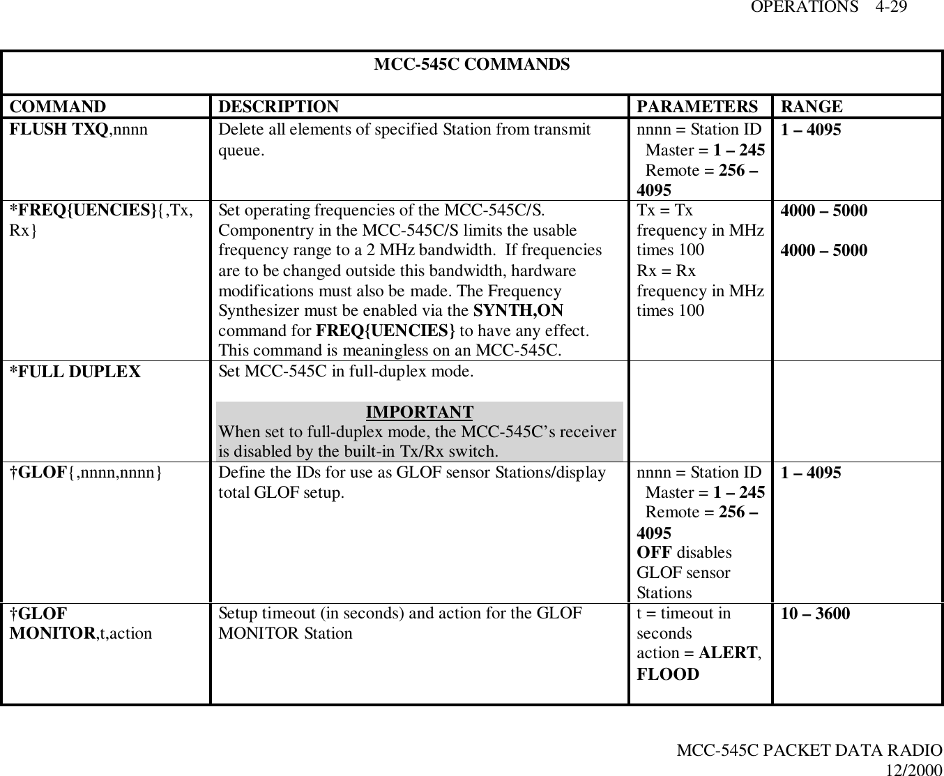
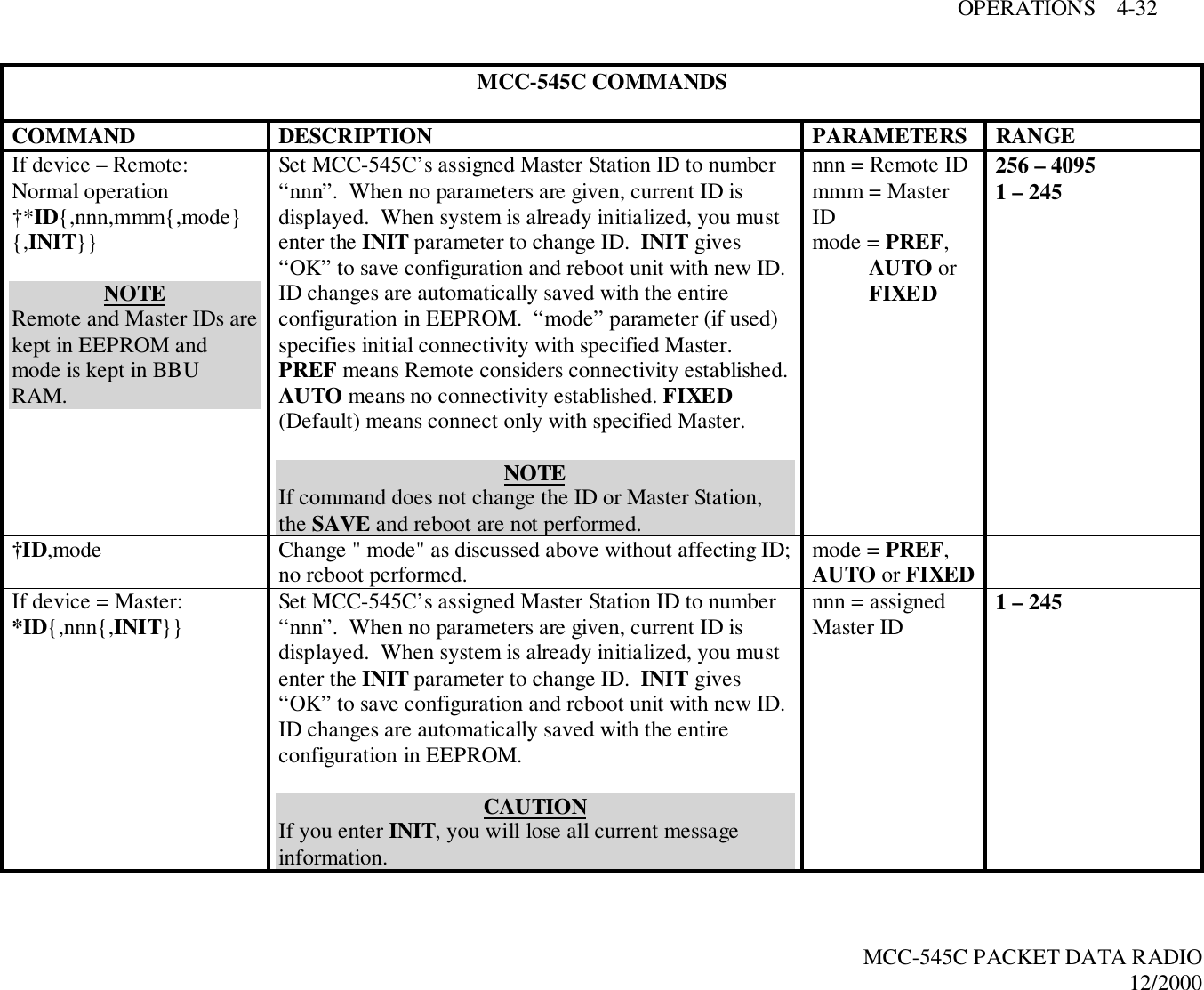
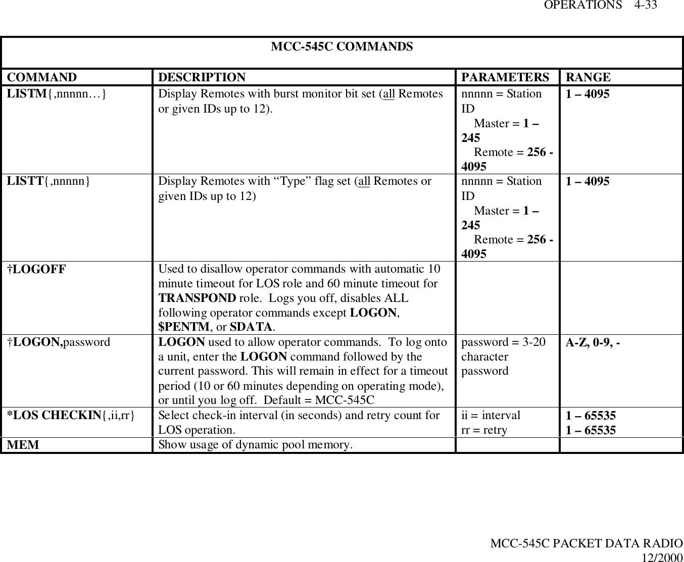
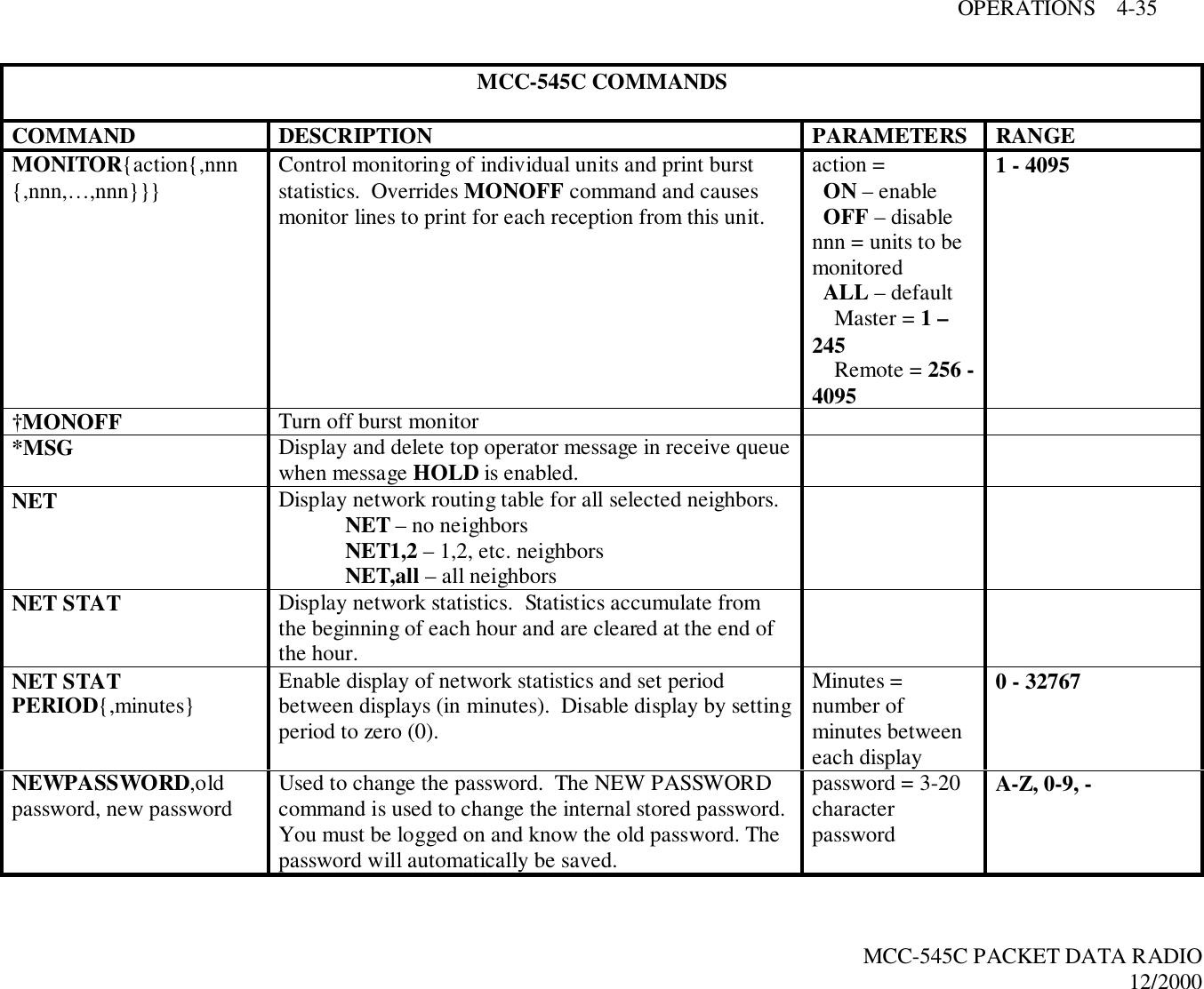
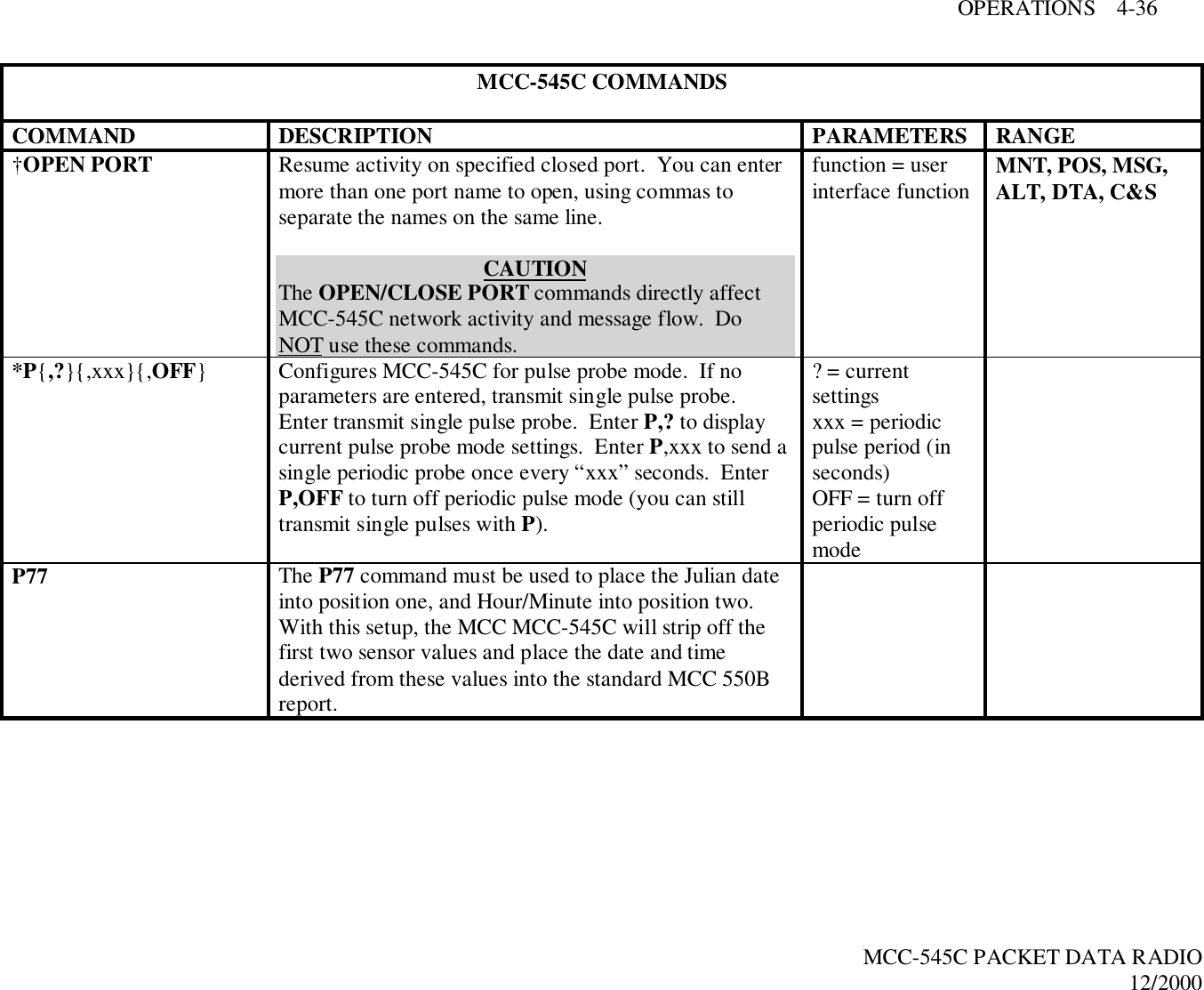
![OPERATIONS 4-1MCC-545C PACKET DATA RADIO12/20004.0 OPERATIONSThis chapter covers the fundamental operating procedures of the MCC-545C and is functionallydivided into seven sections:! Getting Started! Station Operational Parameters! Sending and Receiving Messages! Data Logging! Reporting Position Location! Master Mode Functions! Examining System Statistics4.1 Getting Started4.1.1 Command Entry and EditingYou must enter carriage returns after every command. A list of all the operator commands aregiven in Table 4.2.When a command is accepted, the operator terminal will print the system time. For a descriptionof printouts, see Appendix A.Before you begin you should familiarize yourself with the special editing functions that you canuse when entering commands:[DEL] Deletes last character entered.[CTRL] Prints command line on next line down.[CTRL]-R Repeats last command line\X Removes current line from command buffer.[CR], [LF] or [ENTER] Terminates line and causes the command entered to be executed.4.1.2 Unit Name and Station IDIn command descriptions, the parameter "name" is the assigned Station name. The name is thenumeric Station ID. For more information on MCC-545C operation as either a Remote or MasterStation, refer to Section 4.2.1. Station IDs, represented by "nnnn", can be assigned as follows:1 – 245 Master Station256 – 4095 Remote](https://usermanual.wiki/Meteorcomm/54505001-01/User-Guide-134342-Page-37.png)
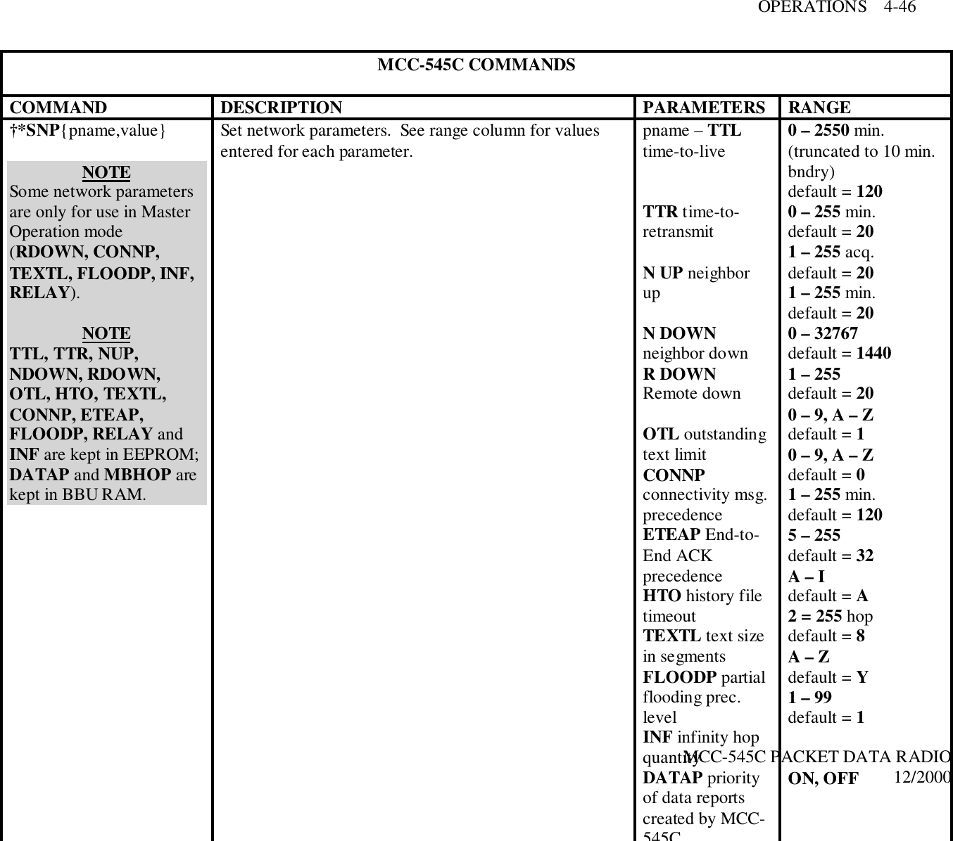
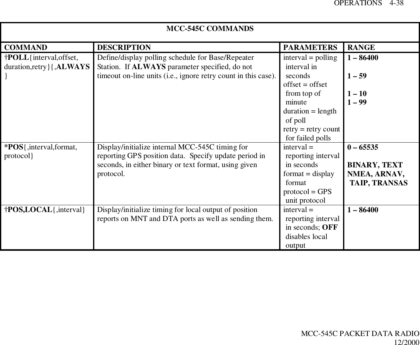
![OPERATIONS 4-6MCC-545C PACKET DATA RADIO12/2000TTR – Time-to-retransmit in minutes (default is 20 minutes); i.e., the message isretransmitted if it has not reached its destination within this time frame.NUP – Neighbor-up threshold (default is 20 acquisitions); the number of times a Stationmust hear from another Station within a one minute time interval before itbecomes a neighbor.NDOWN – Neighbor-down threshold in minutes (default is 20 minutes); if there is nocommunication with a neighboring Station within the set time, the route to thatneighbor is ignored. Setting NDOWN to 0 maintains the routing to the neighborindefinitely.RDOWN – MASTER OPERATION ONLY - Remote-down threshold in minutes (default is1,440 minutes); if there is no communication with a Remote Station within the settime, the Remote is declared down and is removed from the Remote table.Setting RDOWN to 0 keeps a Remote defined indefinitely. OTL – Outstanding text limit (default is 20 texts); the number of messages a Station isallowed to send to another Station without an end-to-end acknowledgment.CONNP – MASTER OPERATION ONLY - Connectivity message precedence (default is 1precedence); information on changes in the connectivity table is given highestprecedence (automatic feature).ETEAP – End-to-end ACK message precedence (default is 0 [zero] precedence); theacknowledgment of a message when it reaches its final destination is givenhighest precedence.HTO – History file timeout in minutes (default is 10 minutes); maintains information forduplicate filtering.TEXTL – MASTER OPERATION ONLY - Text size in segments (default is 32 segments).FLOODP – MASTER OPERATION ONLY - Partial "flooding" precedence level (default isA precedence). Messages of this precedence level and above are transmitted overall routes of minimum length; messages below this precedence are not sent overall minimum length routes, but are sent only over the routes where the shortesttransmit queues exist.MBHOP – meteor burst link hop weight (default is 1 hop). Defines the number of networkhops to associate with a meteor burst Master Station link when determining theminimum path to use in routing a message. MBHOP should be set high enough toprevent a meteor burst Master Station link to be chosen over a line-of-sightRemote to Remote link in a network that is predominantly line-of-sight.INF – MASTER OPERATION ONLY - Infinity hop quantity (default is 8 hops).Defines the width of the network in hops plus one to determine when connectivity](https://usermanual.wiki/Meteorcomm/54505001-01/User-Guide-134342-Page-42.png)
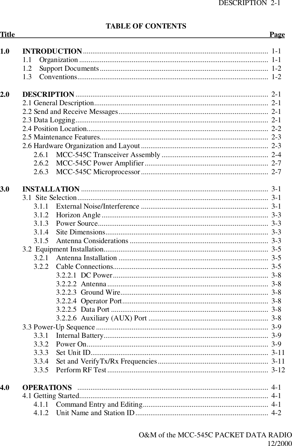
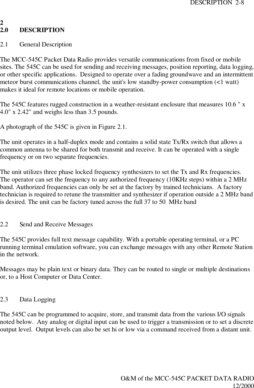
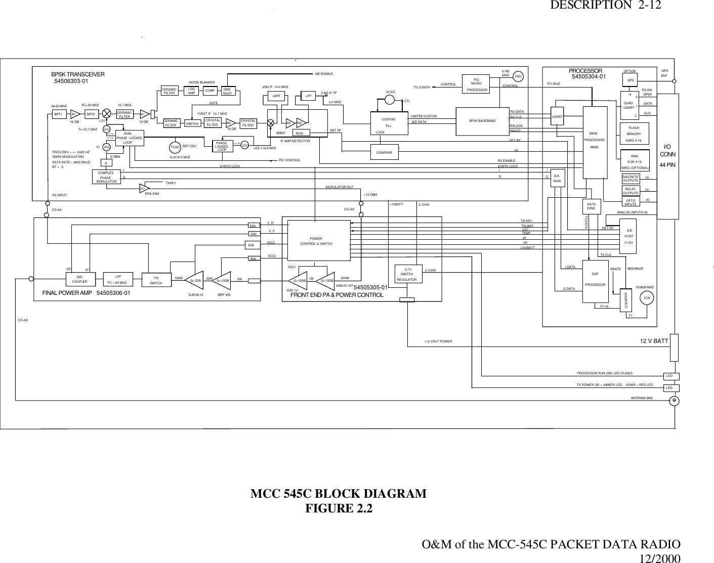
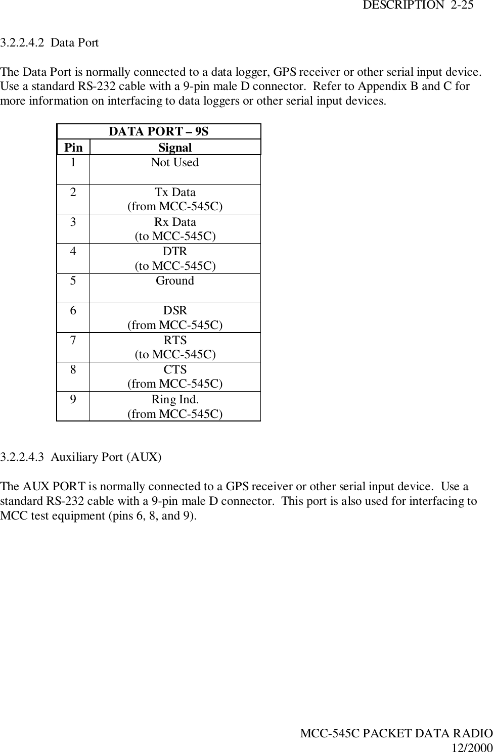
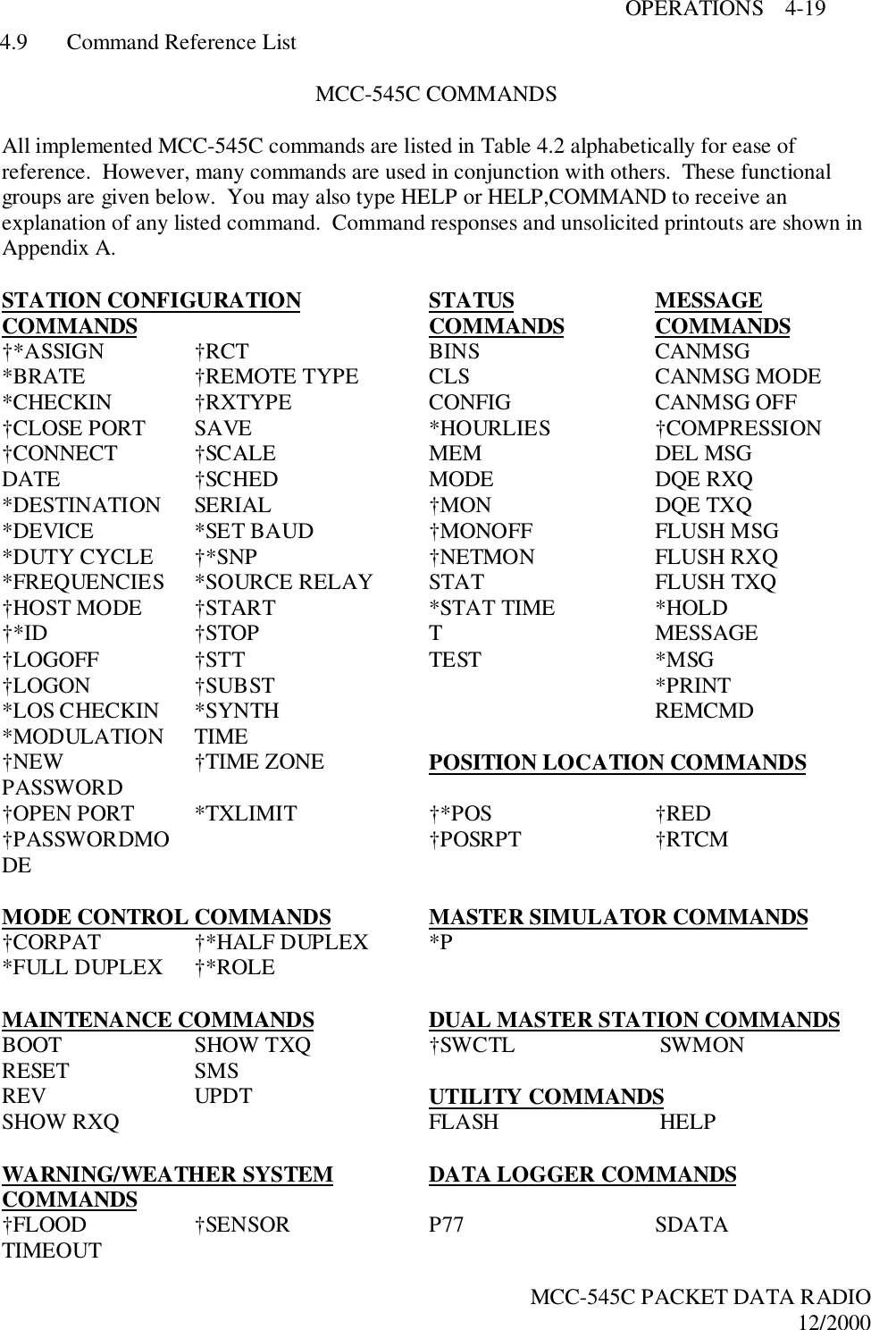
![OPERATIONS 4-12MCC-545C PACKET DATA RADIO12/2000Messages are first entered and edited in the TEXT EDIT BUFFER. They are then transferred toone or more TX QUEUE buffers for transmission to the designated destinations. The diagrambelow depicts the general flow of messages within the MCC-545C software and the variouscommands associated with each step in the process.MESSAGE FLOW AND ASSOCIATED COMMANDSFIGURE 4.3The following operations are explained in this section:SECTION OPERATIONS4.3.1 Entering and Deleting Messages4.3.2 Editing Messages4.3.3 Sending Messages4.3.4 Sending Commands4.3.5 Sending Canned Messages4.3.6 Receiving Messages4.3.7 Examining Message Status4.3.8 Examining and Revising Message Queues4.3.1 Entering and Deleting MessagesAll messages are composed and edited in the TEXT EDIT BUFFER. Messages may be 3,570characters in length. When composing the message press [CR] at the end of each 80 characterline.TX QUEUEPRINTRX QUEUE[SHOW][FLUSH][DEL][SMS][SHOW][FLUSH][DEL][SMS]TEXT EDITBUFFER[MESSAGE][CMD][CANMSG]EDIT COMMANDS[ESC][DEL][ESC]TO/FROMNEIGHBORINGSTATIONSACKEND-TO-END](https://usermanual.wiki/Meteorcomm/54505001-01/User-Guide-134342-Page-48.png)
![OPERATIONS 4-13MCC-545C PACKET DATA RADIO12/2000There is a default destination programmed into the MCC-545C during the installation andinitialization of the unit when it is first brought on-line in the network. If a message is not givena specific destination it will be sent to the default destination only.To enter a message:1. Type MESSAGE. The operator terminal will respond with ENTER TEXT. The MCC-545C will now be in the compose and edit mode.2. Enter a message up to 3,570 characters in length, pressing [CR] at the end of each 80character line.3. Press the [ESC] key. The message will now be transferred to a Tx queue and will beautomatically transmitted to the default destination at a priority level R.The following message will be displayed, or printed, on the operator terminal:hh:mm:ss Message No: name:ss,nnnn chars, nnn segmentshh:mm:ss ROUTING name :sss TXT sss/nn TO: nameIf you wish to send a message to multiple destinations, and at a different priority level,typeMESSAGE, R, dest1, dest2, …dest nwhere: “R” is any priority level from A to Z. A is the highest and Z is the lowest.“Dest” is the numerical ID of the stations to which the message will be routed.NOTEIf you also want to send the message to your default destination you must enter its stationnumerical ID as one of the destination parameters (“dest1”, “dest2”, etc.) as specified above.NOTEIf you want to use source routing enter 0 for the destination ID. When the master stationreceives this message it will send the message to the appropriate destination based on it’s linktable showing which destination(s) are linked with your station. Refer to the master stationmanual for more information on source routing.There are three other special editing functions that may be used:1. To Retransmit A Previously Entered MessageTo retransmit a previously entered message simply depress the [ESC] key after theoperator terminal prints ENTER TEXT and before any other key is depressed. Theprevious message entered into the TEXT EDIT BUFFER will then be sent to thedestinations that are now designated in the MESSAGE command.](https://usermanual.wiki/Meteorcomm/54505001-01/User-Guide-134342-Page-49.png)
![OPERATIONS 4-14MCC-545C PACKET DATA RADIO12/20002. To Revise A Previously Entered MessageTo revise a previously entered message press [CTRL]T after the ENTER TEXT promptto revise a previously entered message or to recover from an aborted session. Theprevious message will be displayed with the cursor placed at the end of the message.You may now resume editing the message.3. To Delete a MessageTo delete a message after it has been placed in the Tx Queue, typeDELMSG, ID: ssswhere: ID is the numerical station IDsss is the message serial numberThe operator terminal will print the date and time, followed by MESSAGE DELETED.4.3.2 Editing MessagesThe following editing functions may be used while the message is in the TEXT EDIT BUFFER.KEY FUNCTION[DEL] Deletes the last character entered.[CTRL]R Prints the current line of text on the next line down.[CTRL]I Performs a fixed tab function\ Removes the current line from the edit buffer.[CR] Performs a carriage return and line feed.[LF] Performs a carriage return and line feed.[CTRL]X Removes the current line from the edit buffer and places thecursor at the end of the previous line.[CTRL]T Prints the contents of the edit buffer.[CTRL]D Erases the entire contents of the edit buffer.[CTRK]A Aborts the edit mode and returns to the command mode.A “+” indicates the command mode.ESC Leaves text edit mode and queues the message for transmission.4.3.3 Sending MessagesMessages are automatically transmitted with the [ESC] command. Each message will be placedin the Tx Queue in accordance with its assigned priority. Messages of equal priority are placedin the Tx Queue in the order received from the TEXT EDIT BUFFER.The following display will appear on the operator terminal as the MCC-545C begins to transmita message:](https://usermanual.wiki/Meteorcomm/54505001-01/User-Guide-134342-Page-50.png)
![OPERATIONS 4-15MCC-545C PACKET DATA RADIO12/2000hh:mm:ss Message No: name:ss,nnnn chars, nnn segmentshh:mm:ss ROUTING name :sss TXT sss/nn TO: nameMessages are transmitted in packets and are routed to their destination in a store and forwardmanner, using the most efficient routing within the packet switched network. The originatingstation will receive an acknowledgement (ACK) if the message has been received successfullyby the first routing station.mm/dd/yy hh:mm:ss TXTMSG ACK name:sss, xxxx CHARS FROM nameWhen the entire message has been delivered to its final destination an end-to-endacknowledgement will be displayed on the operator terminal:hh:mm:ss END-TO-END ACK OF name:sss FROM nameIf the end-to-end ACK is not received within the specified time-to-live limit, the MCC-545C willpurge the message from the Tx Queue and display the following message:hh:mm:ss MESSAGE TIME-TO-LIVE EXPIRED, MSG.NO:sss, DESTN: nameYou must then reenter the message. Continued failure to successfully transmit a messageindicates that something may be wrong with the equipment or the link (e.g., excessive noiseinterference).4.3.4 Sending CommandsCommands may be sent to any remote station within the network. The entry of a command issimilar to the MESSAGE command described in Section 4.3.1.REMCMD, R, dest1, dest2, …destnwhere: R = priority leveldest = numerical ID of destination station(s)The operator is then prompted to enter the text of the command using the message editor. Oncethe command is entered, press the [ESC] key to send the command. The operator terminal willdisplay:A response will be received from the destination station(s) if it was successfully received.hh:mm:ss Message No: name:sss, nnnn chars, nnnDestination IDMessage Number (0- Number ofNumber of 14-character](https://usermanual.wiki/Meteorcomm/54505001-01/User-Guide-134342-Page-51.png)
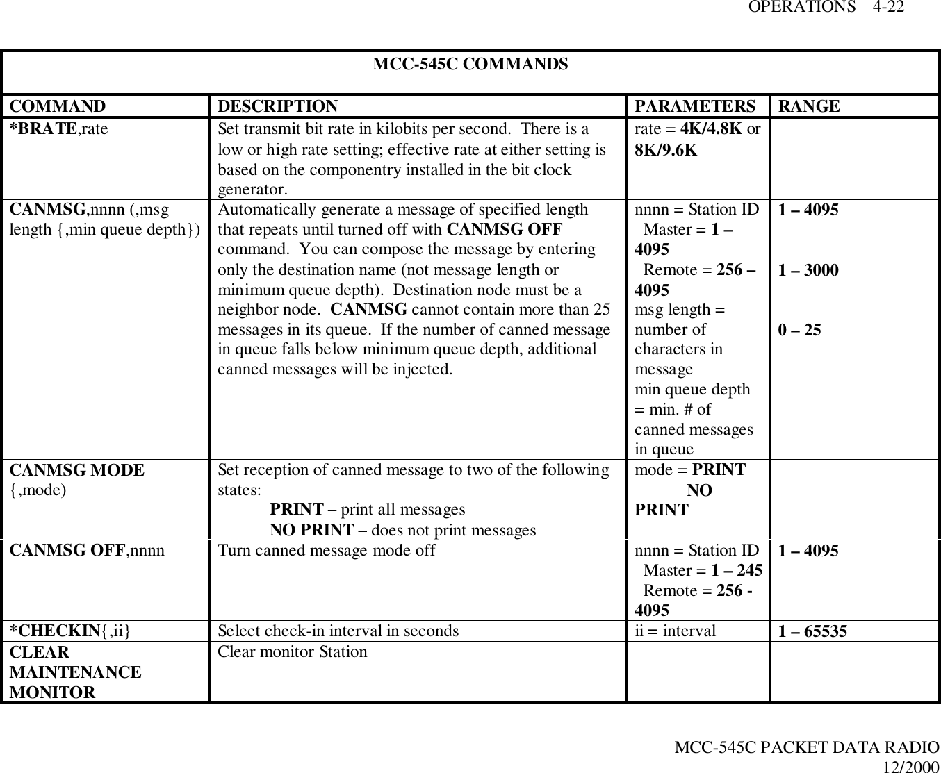
![OPERATIONS 4-16MCC-545C PACKET DATA RADIO12/20004.3.5 Sending Canned MessagesThe MCC-545C may be placed into a canned message mode for automatic transmission of arepetitive message to an assigned neighboring station. In the canned message mode no morethan 25 messages may be placed into the Tx Queue at one time. You may either send an editedtext message or a message that is randomly generated from the alphabet.To enter a canned message generated from the alphabet, enter:CANMSG,id,msg length{,min.queue depth}where “id” is the neighboring station ID, the message length is from 1 to 3000 characters and thequeue depth is from 1 to 25. The default queue depth is 5. Additional canned messages will beinjected if the number of canned messages in the queue falls below the minimum queue depth.To enter an edited canned message, enter:CANMSG,idwhere “id” is the neighboring station’s ID. After composing your message press the [ESC] key.The MCC-545C will automatically route up to 25 copies of the canned message to thedestination station.Each canned message will be acknowledged by the selected neighboring station. No end-to-endacknowledgement will be received.To terminate the mode, enter:CANMSG OFF,idCanned messages are normally not printed at destination station. To print canned messages asthey are received, enter:CANMSG MODE,PRINTTo turn off the print mode, enter:CANMSG MODE,NO PRINT4.3.6 Receiving MessagesWhen a new message is received it is announced by the following display:hh:mm:ss RECEIVING name:sss TXT sss/nn FROM name ROUTED TO: nameThe MCC-545C then generates an ACK of the message packet and transmits the ACK to theneighbor from whom the message was received:](https://usermanual.wiki/Meteorcomm/54505001-01/User-Guide-134342-Page-52.png)
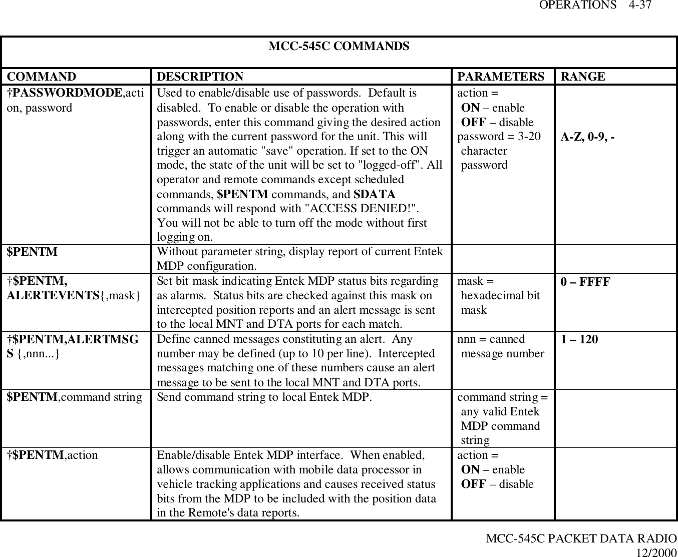
![OPERATIONS 4-34MCC-545C PACKET DATA RADIO12/2000MCC-545C COMMANDSCOMMAND DESCRIPTION PARAMETERS RANGEMESSAGE{,p{,dest1…destn}} Enter a message with text editor. Message priority anddestination are optional parameters. After enteringmessage, press [ESC] to queue for transmission. If youdo not enter a destination ID, the MCC-545Cautomatically sends your message to its defaultdestination (set with the DESTINATION command). Ifyou want to use source rounting, enter 0 for thedestination.p = prioritydest1. . .destn =destination(s)name = nodenamennnn = Station ID Master = 1 –245 Remote = 256 –4095A – Z, 0 – 9A – Z, 0 – 91 – 4095MM Print current value of RF signal on ReceiverMODE Print operating mode information.*MODULATION,degree,encoding Set the transmit modulation and data encoding.IMPORTANT545C modulation must be the same as other units in thenetwork.degree = 90 or 30encoding = MANfor Manchester,DIFF fordifferential†MON{,d{,r}} Turn on burst monitor. Only meteors lasting longenough to deliver “d” characters will be monitored. If atleast “r” characters were received, a monitor line isgenerated.d = durationcharacter countlimitr = receivedcharacter countlimit0 – 327670 – 32767](https://usermanual.wiki/Meteorcomm/54505001-01/User-Guide-134342-Page-70.png)
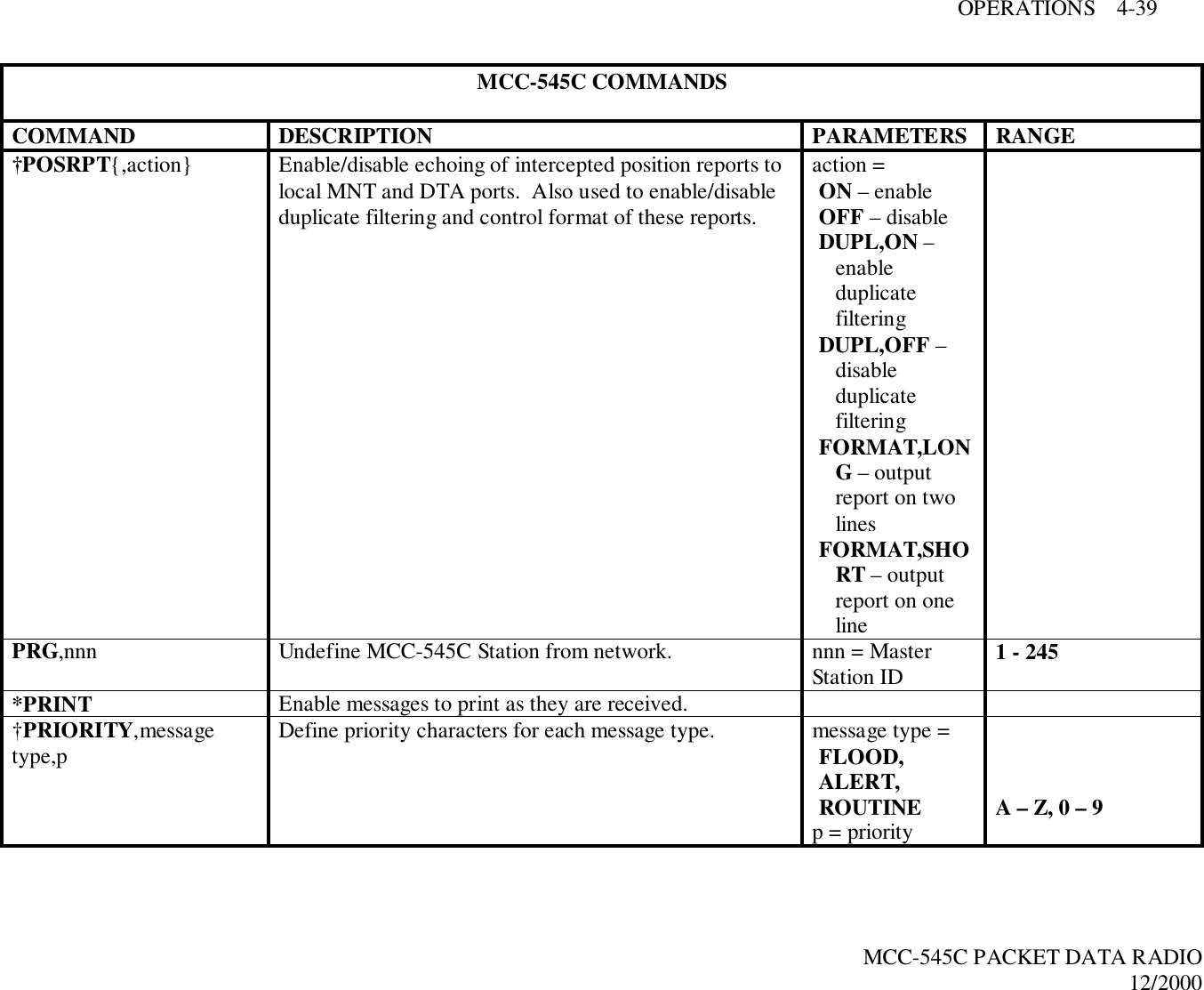
![OPERATIONS 4-41MCC-545C PACKET DATA RADIO12/2000MCC-545C COMMANDSCOMMAND DESCRIPTION PARAMETERS RANGEREMCMD,p,dest1{,…destn} With the text editor, enter a command to be sent to aRemote. After entering command, press [ESC] to sendthe command.p = prioritydest1…destndestination(s) name = nodename nnnn = StationID Master = 1 –245 Remote = 256 –4095A – Z, 0 – 9A – Z, 0 – 91 – 4095REMOTESTAT{,nnnnn…} Display transmit/receive statistics for all Remote Stationsor for given IDs (up to 12). nnnn = Station ID Master = 1 –245 Remote = 256 –40951 – 4095†REMOTETYPE{,aaaaa} Display/set communication characteristics of the unit.Determines how certain statistics are reported and howremote commands/messages are framed.aaaaa =COMMDATAPACKET*REPEATER{,nnn} Define/display Base Station to which the Repeater siterepeats. nnn = BaseStation IDOFF clears apreviouslyestablisheddefinition1 – 245RESET Perform hardware reset to clear and reinitialize I/Ochannels and RF controller. This command retainsprevious network configurations and message traffic.](https://usermanual.wiki/Meteorcomm/54505001-01/User-Guide-134342-Page-77.png)