Meteorcomm 54505001-01 Meteor Burst Packet Data Radio For Fixed Or Mobile User Manual Instruction Manual Exhibit 8
Meteorcomm LLC Meteor Burst Packet Data Radio For Fixed Or Mobile Instruction Manual Exhibit 8
Instruction Manual Exhibit 8
FCC ID: BIB5450500101
EXHIBIT VIII
OPERATION AND MAINTENANCE
OF THE
MCC-545C
PACKET DATA RADIO
FCC ID: BIB5450500101
EXHIBIT VIII
OPERATION AND MAINTENANCE
OF THE
MCC-545C PACKET DATA RADIO
MAN-OM-545C
January 2001
Meteor Communications Corporation
8631 So.212th St..
Kent, WA 98031
Tel: (253) 872-2521
Fax: (253) 872-7662
E-mail: mcc@meteorcomm.com
2000 by Meteor Communications Corporation
all rights reserved

FCC ID: BIB5450500101
EXHIBIT VIII
This page MUST be inserted for any copy of this manual going to the United Kingdom.
WARNING WARNING WARNING
Certain power transistors used in this equipment and their associated heatsink components are
manufactured partly or wholly from a beryllium compound. Normally these can be handled
without risk of toxicity, but there is a toxic hazard if dust or finely-divided particles of the
material are inhaled or enter the body through a cut. Consequently, great care must be taken, and
hands must be washed after handling.
Any cuts or abrasions on the hands must be covered by dressings while such components are
being handled. If beryllium dust does enter the skin through a cut or abrasion, the affected part
must be washed thoroughly and treated by a doctor.
Components containing beryllium may only be machined, cut, abraded, or heated above 400 C
under strictly controlled conditions approved by the appropriate Safety Authority.
Disposal of Beryllium
Disposal of faulty components must be carried out according to special arrangements. Should a
component containing Beryllium be broken, its parts and particles must be gathered carefully
using a moistened tissue (preferably while wearing plastic or rubber gloves), placed in a plastic
bag together with any contaminated materials, sealed, labeled, and disposed of in a manner
approved of by the Safety Authority.
Beryllium Components in MCC-545C RF Power Components
RF power components in the modules listed below incorporate some Beryllium within the
transistor package and must be handled as specified in the above warning notice.
TRANSISTOR CIRCUIT MODULE MANUFACTURER REFERENCE
545C 100W Transmitter (54505302-01) Advanced Semi Corp
Motorola Q1,Q4
Q2

FCC ID: BIB5450500101
EXHIBIT VIII
GENERAL WARRANTY
Meteor Communications Corporation (MCC) warrants that its products conform to the
published specifications and are free from manufacturing and material defects for one year after
shipment. Warranty-covered equipment that fails during the warranty period will be promptly
repaired at MCC’s facility in Kent, Washington.
International customers shall pay shipping costs to the MCC facility, with Seattle as the point of
U.S. entry. MCC shall pay incoming U.S. duty fees. MCC shall pay for shipping costs to return
the equipment to the customer, with the customer paying any and all return duty fees.
This warranty is contingent upon proper use of the equipment and does not cover equipment that
has been modified in any way without MCC’s approval or has been subjected to unusual
physical or electrical stress, or on which the original identification marks have been removed or
altered.

FCC ID: BIB5450500101
EXHIBIT VIII
REVISION PAGE
Document Title MCC-545C INSTALLATION AND OPERATIONS Manual
Document Number:
Revision # Date Revision
Redline 11/10/2000 Redline Release
01/03/2001 Initial Release
A
B
C
D
E
F
G
H
I

DESCRIPTION 2-1
O&M of the MCC-545C PACKET DATA RADIO
12/2000
TABLE OF CONTENTS
Title Page
1.0 INTRODUCTION................................................................................................... 1-1
1.1 Organization ..................................................................................................... 1-1
1.2 Support Documents.......................................................................................... 1-2
1.3 Conventions...................................................................................................... 1-2
2.0 DESCRIPTION ....................................................................................................... 2-1
2.1 General Description............................................................................................. 2-1
2.2 Send and Receive Messages................................................................................ 2-1
2.3 Data Logging....................................................................................................... 2-1
2.4 Position Location................................................................................................. 2-2
2.5 Maintenance Features.......................................................................................... 2-3
2.6 Hardware Organization and Layout .................................................................... 2-3
2.6.1 MCC-545C Transceiver Assembly ......................................................... 2-4
2.6.2 MCC-545C Power Amplifier.................................................................. 2-7
2.6.3 MCC-545C Microprocessor.................................................................... 2-7
3.0 INSTALLATION .................................................................................................... 3-1
3.1 Site Selection...................................................................................................... 3-1
3.1.1 External Noise/Interference .................................................................... 3-1
3.1.2 Horizon Angle......................................................................................... 3-3
3.1.3 Power Source........................................................................................... 3-3
3.1.4 Site Dimensions....................................................................................... 3-3
3.1.5 Antenna Considerations .......................................................................... 3-3
3.2 Equipment Installation........................................................................................ 3-5
3.2.1 Antenna Installation ................................................................................ 3-5
3.2.2 Cable Connections................................................................................... 3-5
3.2.2.1 DC Power................................................................................... 3-8
3.2.2.2 Antenna ...................................................................................... 3-8
3.2.2.3 Ground Wire............................................................................... 3-8
3.2.2.4 Operator Port.............................................................................. 3-8
3.2.2.5 Data Port .................................................................................... 3-8
3.2.2.6 Auxiliary (AUX) Port ................................................................ 3-8
3.3 Power-Up Sequence............................................................................................ 3-9
3.3.1 Internal Battery........................................................................................ 3-9
3.3.2 Power On................................................................................................. 3-9
3.3.3 Set Unit ID............................................................................................... 3-11
3.3.4 Set and VerifyTx/Rx Frequencies........................................................... 3-11
3.3.5 Perform RF Test...................................................................................... 3-12
4.0 OPERATIONS ...................................................................................................... 4-1
4.1 Getting Started..................................................................................................... 4-1
4.1.1 Command Entry and Editing................................................................... 4-1
4.1.2 Unit Name and Station ID....................................................................... 4-2

DESCRIPTION 2-2
O&M of the MCC-545C PACKET DATA RADIO
12/2000
Title Page
4.1.3 HELP Command .................................................................................... 4-2
4.1.4 System Time and Date ............................................................................ 4-2
4.2 Station Operational Parameters........................................................................... 4-3
4.2.1 Configuring the MCC-545C.................................................................... 4-3
4.2.2 Selecting MCC-545C Remote/Master Operation ................................... 4-5
4.2.3 Selecting Network Parameters................................................................ 4-5
4.2.4 Selecting the Burst Monitor .................................................................... 4-7
4.2.5 Controlling the Hourly Statistics Report................................................. 4-8
4.2.6 Scheduling MCC-545C Events ............................................................... 4-8
4.2.7 Setting Timeout Durations ...................................................................... 4-9
4.2.8 Setting Frequencies ................................................................................. 4-9
4.2.9 Defining Data Relays .............................................................................. 4-10
4.2.10 Scaling A/D Readings ............................................................................. 4-11
4.3 Sending and Receiving Messages ....................................................................... 4-12
4.3.1 Entering and Deleting Messages ............................................................. 4-12
4.3.2 Sending Commands to Remote Stations ................................................. 4-14
4.3.3 Editing Messages..................................................................................... 4-14
4.3.4 Transmitting Messages............................................................................ 4-15
4.3.5 Receiving Messages............................................................................... 4-16
4.3.6 Examining/Revising Messages Queues................................................... 4-16
4.3.7 Examining Message Statistics................................................................. 4-18
4.3.8 Entering Canned Messages...................................................................... 4-18
4.3.9 Printing Canned Messages ...................................................................... 4-19
4.4 Data Loggers ....................................................................................................... 4-19
4.5 Reporting Position Location................................................................................ 4-19
4.6 Master Simulator Mode....................................................................................... 4-20
4.7 Examining Station Statistics................................................................................ 4-22
4.8 Configuring an RF Network................................................................................ 4-23
4.8.1 Types of Networks .................................................................................. 4-23
4.8.1.1 Meteor Burst Networks............................................................ 4-24
4.8.1.1.1 Full Duplex Network.............................................. 4-25
4.8.1.1.2 Half Duplex Network............................................. 4-26
4.8.1.1.3 Master Probe/Transpond Role................................ 4-26
4.8.1.1.4 Master Active/Passive Role.................................... 4-26
4.8.1.2 Line-of-Sight Networks............................................................ 4-27
4.8.1.2.1 Multi-Master Mode ................................................ 4-28
4.8.1.2.2 Base/Repeater Mode .............................................. 4-28
4.8.2 Remote to Master Assignment ................................................................ 4-30
4.8.2.1 Fixed Master Selection............................................................. 4-30
4.8.2.2 Preferred Master Selection....................................................... 4-30
4.8.2.3 Automatic Master Selection..................................................... 4-32
4.8.3 Destination Considerations...................................................................... 4-32
4.8.4 Source and Group Routing...................................................................... 4-33
4.8.5 Network Parameters................................................................................ 4-34

DESCRIPTION 2-3
O&M of the MCC-545C PACKET DATA RADIO
12/2000
Title Page
4.9 Command Reference List.................................................................................... 4-37
APPENDIX A
Command Printouts
Unsolicited Printouts
APPENDIX B
Data Logger Interface
APPENDIX C
GPS Interface
APPENDIX D
Application Note: MCC-545C PACKET DATA RADIO Warning Software
APPENDIX E
Application Note: CR10X Data Logger
APPENDIX F
Event Programming
LIST OF FIGURES
Figure Page
2.1 MCC-545C Photograph............................................................................................. 2-2
2.2 MCC-545C Block Diagram....................................................................................... 2-5
2.3 MCC-545C Outline Drawing.................................................................................... 2-6
3.1 Remote Station Antenna Height for Meteor Burst.................................................... 3-4
LIST OF TABLES
Table Page
2.1 MCC-545C General Specifications........................................................................... 2-8
2.2 MCC-545C Receiver Specifications......................................................................... 2-8
2.3 MCC-545C Transmitter Specifications..................................................................... 2-9
2.4 MCC-545C Multiprocessor Specifications ............................................................... 2-9
3.1 MCC-545C Interface Connections............................................................................ 3-6
4.1 MCC-545C Scaling Factors ...................................................................................... 4-11
4.2 MCC-545C Commands............................................................................................. 4-40

DESCRIPTION 2-4
O&M of the MCC-545C PACKET DATA RADIO
12/2000
DESCRIPTION 2-5
O&M of the MCC-545C PACKET DATA RADIO
12/2000
1.0 INTRODUCTION
The MCC-545B PACKET DATA RADIO is part of a Meteor Burst Communications System
(MBCS) that allows short and long range communications between any two Stations in the
system. The system offers continuous radio signal propagation via ground wave and meteor
burst. Ground wave covers short distances, up to 100 km (60 miles). Meteor burst covers longer
distances, up to 1,600 km (1,000 miles), reflecting signals off ionized electron trails created by
meteors entering the atmosphere at a height of about 100 km (60 miles) above the earth's surface.
These trails, called bursts, are random but predictable in number and last from a few
milliseconds to several seconds. During this time, information can be exchanged between two
Stations. The height of the trails (60 miles) gives the system its 1,000 mile range.
1.1 Presentation
This manual is divided into five major sections:
Section 2. DESCRIPTION
Discusses specifications of each module included in the 545B.
Section 3: INSTALLATION
Presents a brief outline of installation procedures for the 545B. Includes
considerations for set-up and cabling, as well as power-up procedures.
Section 4: OPERATION
Outlines operating procedures for hardware and software.
Appendix A contains printouts of 545B commands and command responses.
Appendix B contains for interfacing the Pharos Marine Data Acquisition Unit.
Appendix C contains a list of GPS units supported and instructions for interfacing each unit to
the 545B.
Appendix D contains information on configuring the 545B for use in a Flood Warning System.
Appendix E contains information on interfacing to the Campbell Scientific CR10X Data Logger.
Appendix F contains information on the event and I/O programming capability of the 545B.

DESCRIPTION 2-6
O&M of the MCC-545C PACKET DATA RADIO
12/2000
1.2 Support Documents
Customer Specific System Manual
MCC-520B/MCC-520C Operations Manual
1.3 Conventions
The following conventions are used in this manual:
Any system-dependent options are indicated with an "*".
When presented in the text, user commands and computer printout are boldfaced; e.g., Enter
DELETE. Command parameters are presented in lower case; e.g., DEFINE,id. Optional
parameters are enclosed in brackets; e.g., TIME{,hh:mm:ss}
Names of terminal keys are capitalized and enclosed in square brackets when mentioned in the
text; e.g., Press [ESC].
Names of hardware switches, meters, etc. are capitalized; e.g., PWR ON switch.
NOTE
Used for special emphasis of material
IMPORTANT
Used for added emphasis of material.
CAUTION
Signals the operator to proceed carefully.
WARNING! WARNING! WARNING!
Used in cases where failure to heed the message may result in personal injury or equipment
damage.

DESCRIPTION 2-7
O&M of the MCC-545C PACKET DATA RADIO
12/2000
DESCRIPTION 2-8
O&M of the MCC-545C PACKET DATA RADIO
12/2000
2
2.0 DESCRIPTION
2.1 General Description
The MCC-545C Packet Data Radio provides versatile communications from fixed or mobile
sites. The 545C can be used for sending and receiving messages, position reporting, data logging,
or other specific applications. Designed to operate over a fading groundwave and an intermittent
meteor burst communications channel, the unit's low standby-power consumption (<1 watt)
makes it ideal for remote locations or mobile operation.
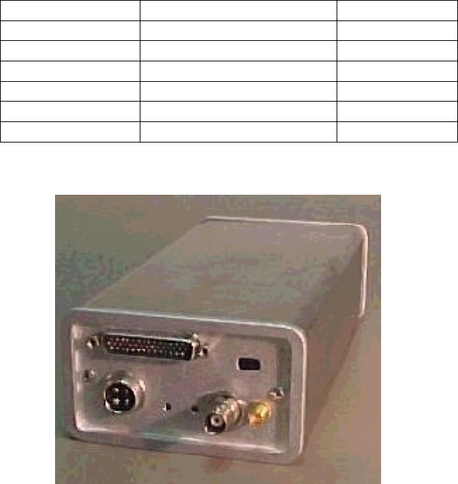
The 545C features rugged construction in a weather-resistant enclosure that measures 10.6 " x
4.0" x 2.42" and weighs less than 3.5 pounds.
A photograph of the 545C is given in Figure 2.1.
The unit operates in a half-duplex mode and contains a solid state Tx/Rx switch that allows a
common antenna to be shared for both transmit and receive. It can be operated with a single
frequency or on two separate frequencies.
The unit utilizes three phase locked frequency synthesizers to set the Tx and Rx frequencies.
The operator can set the frequency to any authorized frequency (10KHz steps) within a 2 MHz
band. Authorized frequencies can only be set at the factory by trained technicians. A factory
technician is required to retune the transmitter and synthesizer if operation outside a 2 MHz band
is desired. The unit can be factory tuned across the full 37 to 50 MHz band
2.2 Send and Receive Messages
The 545C provides full text message capability. With a portable operating terminal, or a PC
running terminal emulation software, you can exchange messages with any other Remote Station
in the network.
Messages may be plain text or binary data. They can be routed to single or multiple destinations
or, to a Host Computer or Data Center.
2.3 Data Logging
The 545C can be programmed to acquire, store, and transmit data from the various I/O signals
noted below. Any analog or digital input can be used to trigger a transmission or to set a discrete
output level. Output levels can also be set hi or low via a command received from a distant unit.
DESCRIPTION 2-9
O&M of the MCC-545C PACKET DATA RADIO
12/2000
I/O CAPABILITY OF MCC 545C
NAME RANGE QUANTITY
Analog Inputs 0 to +5V 6
Digital Inputs Optical isolated 4
Digital Outputs RS232 (+/- 10V) 2
Digital Outputs 0 to +5V ( 10 ma) 3
Digital Inputs 0 to + 5V or +/-10V 2
Relay Outputs Form C 2 amp rating 2
MCC-545C PHOTOGRAPH
FIGURE 2.1
Refer to Appendix E for detailed operation and control of the I/O capability of the MCC 545C.
The MCC can also be connected via an RS 232 port to a variety of Data Loggers such as the
Campbell Scientific CR10X or CR23. Data from these loggers can be collected, stored, and
transmitted to a distant unit. Refer to Appendix B and E for a description of data logger
interface.
2.4 Position Location
The 545C delivers location data from either a built 12 channel GPS (optional) or from an
external GPS with NEMA 0183 format, positioning equipment used in mobile units on land, in
the air, and at sea. The 545C sends the position location to a Master or Base Station, which
forwards the information to a Data Center or Host Computer for processing. This data can be
used in dispatch centers, corporate/district offices, and other monitoring Stations for updating
DESCRIPTION 2-10
O&M of the MCC-545C PACKET DATA RADIO
12/2000
map displays or additional functions. Refer to Appendix B for a description of the GPS
commands.
2.5 Maintenance Features
An operator terminal or a remote command from a distant unit can also be used to read and
display the 545C's status such as radio propagation channel statistics, battery voltage during
transmission (loaded), battery voltage when not transmitting (unloaded), RF forward and
reflected power (checks antenna), and receiver noise levels. It can also be used to display and
configure the 545C's operating characteristics, as detailed in Chapter 4.
An internal Li ion battery is used to maintain the internal real time clock and battery backed
RAM. This battery is capable of operating the clock in a power down state for a period of
approximately 6 months. This battery should be removed if the unit is stored without power for
extended periods of time.
2.6 Hardware Organization and Layout
The unit contains five printed circuit assemblies:
A 100 watt all solid-state 2 stage power amplifier.
A 2 watt 2 stage preamplifier and power switch.
A BPSK 4 KB/sec transceiver containing a BPSK receiver, vector phase modulator (+13Dbm
output) and three frequency synthesizers.
A low-power microprocessor controller used to perform radio control and link and network
protocol functions. This assembly also contains a digital signal processor (DSP)and
digital to analog converter (DAC)for generating the in-phase (I) and quadrature-phase
(Q) base band signals required to generate the BPSK RF signal.
An 8 channel GPS receiver (optional)
The following paragraphs contain a brief description of each of the five main hardware elements
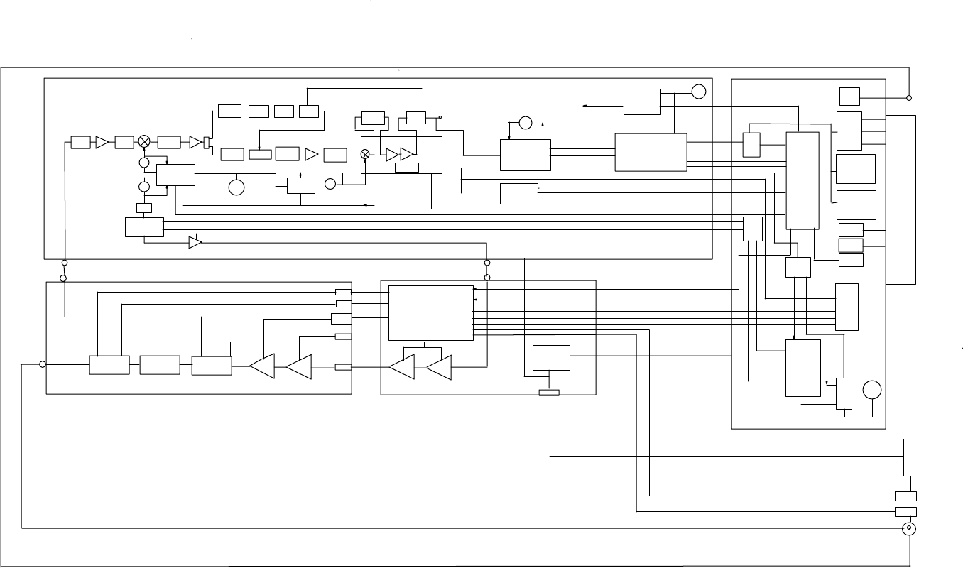
in the 545C. Figure 2.2 presents a block diagram for the 545C. Figure 2.3 presents an outline
drawing showing mounting holes, connectors, and dimensions.

DESCRIPTION 2-11
O&M of the MCC-545C PACKET DATA RADIO
12/2000
2.6.1 MCC-545C Transceiver Assembly
The receiver assembly contains a complete 4K baud Bi Phase Shift Key (BPSK) receiver, a
transmit and receive frequency synthesizer module, and a 4K baud BPSK modulator.
BPSK Receiver
! Input band pass filter (37-50 MHz)
! RF amplifier (17 dB)
! Low pass image filter (Fc=50 MHz)
! Mixer
! IF amplifiers and filters (10.7 MHz)
! Noise blanker
! Mixer, 2nd IF filter and amplifier (100 KHz), and RSSI circuit
! Coherent Costas Carrier Tracking Loop
! BPSK bit detector and clock generator
Synthesizer (1st and 2nd local oscillator and transmit oscillator)
! Reference Oscillator (12.8 MHz +/- 2.5 PPM)
! Tx phase lock loop ( 74-100 MHz output, 20 KHz steps)
! A divide by 2 circuit (37-50 MHz output, 10 KHz steps)
! Rx 1st local oscillator phase lock loop (47.7-60.7 MHz output, 10 KHz steps)
! Rx 2nd local oscillator phase lock loop (10.6 MHz)
! PIC Microcontroller
BPSK Modulator
1. I/Q Vector Phase Modulator (BPSK)
2. Pre amplifier (+13 DBM output)
All components are located on a 8.5”by 3.5” two sided printed circuit board. All components are
soldered in (surface mounted). As an option the board can be conformal-coated with an acrylic
encapsulate that contains a tropicalizing, anti-fungal agent to increase durability and provide
protection against moisture and contamination.
DESCRIPTION 2-12
O&M of the MCC-545C PACKET DATA RADIO
12/2000
MCC 545C BLOCK DIAGRAM
FIGURE 2.2
OPTION GPS
4.192 PROCESSOR
NB ENABLE ANT
54505304-01
MHZ
BPSK TRANSCEIVER OSC
GPS
PIC
54506303-01 NOISE BLANKER PCI BUS
MICRO
CONTROL CONTROL
TO SYNTH
2ND IF 14.2 MHZ RS 232
CERAMIC LOG ONE
COMP PROCESSOR
VCXO
2 ND IF TPFILTER AMP SHOT 4 OPER
CTL 0
LPFLBPF
DATA
QUADGATE 4.2 MHZ
FC=50 MHZ 10.7 MHZ 139-50 MHZ USART
AUX
A1 LIMITED COSTAS 2
RX DATA
A1BPF1 BPF2 CERAMIC FIRST IF 10.7 MHZ USARTFILTER RX CLK
CERAMICLO1 I&D DATA RXLOCK
FILTER FILTER FILTER
SWITCH CRYSTAL COSTAS
CRYSTAL BPSK BASEBAND
16 DB 16 DB A2 A2 A2 PLL FLASH
BRATE
DET RF
VCOFr+10.7 MHZ 16 DB
MAINRSSI
AD607 LOCK MEMORY
DUAL
DC CTRL
PHASE LOCKED 1MEG X 16
PROCESSOR
DET RF
DC CTRL IF AMP/DETECTOR
LOOP I/O
68332VCO TCXO
PHASE DC CTRL VCO
LOCKED
REF OSC
Ft LO2 114.9 MHZ SP
LOOP
FREQ DEV = +/- 2400 HZ COMPARE CONN
RAM
12.8/10.0 MHZ
GMSK MODULATION 0 DBM
512K X 16
RX ENABLE
PIC CONTROL
DATA RATE = 9600 BAUD /2 44 PIN
SYNTH LOCKSYNTH LOCK
BT = .5 IMEG (OPTIONAL)
III
COMPLEX
(3)
DISCRETE
QQD/A
PHASE QOUTPUTS
DUAL
MODULATOR TXKEY MODULATOR OUT (2)
RELAY
A1
OUTPUTS
+13 DBM
ERA-5SM
RX INPUT
(4)
OPTO
INPUTSDATA+12BATT 5.7VRX
CO-AX SYNC
CO-AX ANALOG INPUTS (6)
TX DATA
TX KEY
V_R TXLIMITEMI DET RF
I/O7 A/D
V_F TEMP
EMI 10 BIT
VF
POWER
11 CHVRVCC3 CONTROL & SWITCH
EMI +12VBATT
TX CLK
VCC2
EMI
I DATAVCC1 BRATE 9600 BAUD
5.7V
VR VF 5.7VPR
SWITCH DSP
LPF .020W REGULATOR
2W
100W
DIR 20W
T/R .1W
G=7DB G=13DB G=10DBG=10DB
FC = 60 MHZ
COUPLER SWITCH PROCESSOR
VHB121-12T 54505305-01 19.6608 MHZ
Q DATA
VLB1-12
FINAL POWER AMP 54505306-01 FRONT END PA & POWER CONTROL
VLB100-12 MRF 455 CLK
COUNTER
F1/16
F1
CO-AX
+12 VOLT POWER 12 V BATT
PROCESSOR RUN (ON) LED (FLASH) LED
TX POWER OK = AMBER LED VSWR = RED LED LED
ANTENNA BNC

DESCRIPTION 2-13
O&M of the MCC-545C PACKET DATA RADIO
12/2000
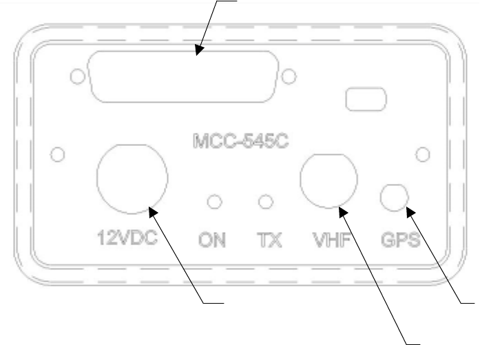
MCC 545C OUTLINE DRAWING
FIGURE 2.3
DESCRIPTION 2-14
MCC-545C PACKET DATA RADIO
12/2000
2.6.2 MCC-545C Power Amplifier
The power amplifier assembly contains two printed circuit boards. One board, the 100 watt
power amplifier, is mounted inside an aluminum enclosure to provide RF shielding between the
low level phase lock loop synthesizers and the high power output. This board contains a T/R
switch for half-duplex operation, a harmonic low pass filter, and a dual directional coupler for
power level control.
The second board contains two low level amplifiers which amplify the 20 milliwatt input signal
from the modulator to a two watt level required by the final power amplifier stage.
All transmitter components are located on a two 4.0" x 3.5’’ printed circuit boards. All
components are soldered in place. As an option the boards can be conformal-coated with an
acrylic encapsulate that contains a tropicalizing, anti-fungal agent to increase durability and
provide protection against moisture and contamination.
Both printed circuit boards are mounted to an aluminum heat sink assembly.
2.6.3 MCC-545C Microprocessor
The microprocessor is a Motorola-based, embedded computer housed on a single PCB that
contains:
! 512K x 16 of non-volatile flash memory for program storage
! Additional 512K x 16 of non-volatile flash memory for parameter storage
! 1024K x 8 of static RAM for data storage (optionally 2048K x 8)
! External RS-232 I/O ports (3)
! Internal TTL GPS port
! Transmitter communication port
! Receiver communication port
! 10-bit 11 channel A/D converter (6 channels available for external sensors)
! Real-time clock
! Power fail detection circuitry
! Digital Signal Processor with D/A converters
! Optically isolated digital inputs (6)
! Form C Relay Outputs (2) with current rating of 2 amps.
All I/O ports are RS 232 compatible and can be programmed to adapt to various customer
protocols. The DATA port contains full flow control hardware lines.
The A/D converter measures TX forward and reverse power, battery voltage, antenna noise
voltage, transmitter board temperature, and 6 channels of 0-5V external sensor inputs.
All processor components are located on a 198mm x 95mm (7.8” x 3.75”). All components are
soldered in place using the latest in surface mount technologies. As an option the board can be

DESCRIPTION 2-15
MCC-545C PACKET DATA RADIO
12/2000
conformal-coated with an acrylic encapsulate that contains a tropicalizing, anti-fungal agent to
increase durability and provide increased protection against moisture and contamination.
Specifications for the unit and the individual circuit boards are given in Tables 2.1 through 2.4.
MCC-545C GENERAL SPECIFICATIONS
CHARACTERISTIC SPECIFICATION
Dimensions 10.6”L X 4.0”W X 2.42”H
Weight 3.5 lbs.
Temperature Range -30° to 60° C (-22° to 140° F)
Power Requirements 12 VDC Nominal (10-14 VDC)
Standby: 80 ma (Continuous)
Transmit: 25 Amps Nominal (100 msec)
TABLE 2.1
MCC-545C RECEIVER SPECIFICATIONS
CHARACTERISTIC SPECIFICATION
Frequency 37-50 MHz .0005%
Synthesized 10KHz steps
Modulation: Type
Rate
Format
GMSK
9.6 kbps and 19.2 kbps
NRZ
Noise Figure < 7 db minimum
Sensitivity: Bit Error Rate < 10-3 at 9.6
kbps -114 dbm
IF Bandwidth (3/80 db) 13/40 KHz typical
RF Bandwidth (3 db) 13 MHz typical
Signal Acquisition Time < 5 msec
3rd Order Intercept Point >- 4 dbm
Image Response Attenuation > 70 db minimum
Spurious Response Attenuation > 70 db minimum
SP Threshold Adjustable from –115 to –106 dbm
Triggered by DET RF and Demodulator Lock
Noise Blanker > 20 db Reduction in Impulse Noise
I/O MCC Standard (Refer to Section 3.2)
TABLE 2.2

DESCRIPTION 2-16
MCC-545C PACKET DATA RADIO
12/2000
MCC-545C TRANSMITTER SPECIFICATIONS
CHARACTERISTIC SPECIFICATION
Frequency 37-50 MHz .0005% Synthesized 10KHz
steps
RF Power Output > 100 Watts at 12 VDC Input
Load VSWR < 2:1 Rated Power
Harmonic Levels 70 db below Unmodulated Carrier
Modulation: Type
Rate
Format
GMSK
9.6 kbps and 19.2 kbps
NRZ
Spurious > 70 db below Unmodulated Carrier
Transmit Modulation Spectrum 10 KHz offset – 40 db
25 KHz offset – 70 db
Tx Duty Cycle 16% Max without shutting down transmitter
20% will shut down the transmitter
T/R Switch Solid-State
Switching Time < 100 microseconds
I/O MCC Standard (Refer to Section 3.2)
High VSWR Protection Withstands Infinite VSWR
TABLE 2.3
MCC-545C MICROPROCESSOR SPECIFICATIONS
CHARACTERISTIC SPECIFICATION
Main Processor Motorola MC68332FC 32-bit Embedded
Controller
Memory: Program Storage
Data Storage
Parameter Storage
512K x 16 non-volatile Flash memory
1024K x 8 static RAM (optional 2048K x 8)
512K x 16 non-volatile Flash memory
Switches: S1 System Reset, Momentary
Jumper: JP2
JP3
JP4
Modulation Select (In for GMSK, Out for
BPSK)
DSP Clock Select (pins 1-2)
Mod Filter Select (In for BT=0.5, Out for
BT=1.0)
TABLE 2.4

DESCRIPTION 2-17
MCC-545C PACKET DATA RADIO
12/2000

DESCRIPTION 2-18
MCC-545C PACKET DATA RADIO
12/2000
3.0 INSTALLATION
This section provides general information on site selection and installation of the MCC-545C for
operation in both an MBCS and ELOS network.
3.1 Site Selection
One of the most important considerations for proper operation in a meteor burst network is the
selection of the operating site. There are a number of factors to consider in selecting an optimum
site:
1. External Noise/Interference
2. Horizon angle
3. DC power source
4. Site dimensions
5. Antenna considerations
These factors are particularly important for meteor burst operation, however, many are
applicable for ELOS operation as well.
3.1.1 External Noise/Interference
Noise and signal interference can reduce the performance of the MCC-545C. The most common
sources of noise and interference are as follows:
! Cosmic Noise
! Power Line Noise
! Automobile Ignition Noise
! Computer-Generated Interference
! External Signal Interference
Cosmic Noise
Cosmic noise is the limiting noise factor in a meteor burst system. This noise is generated by star
systems in the galaxy and is frequency dependent. The noise is approximately 15 db above
thermal at 40 MHz and 13 db above thermal at 50 MHz. The noise is also diurnal in nature. It is
the highest when the antennas are pointed directly at the center of the galaxy and lowest when
they are pointed at right angles to it. Daily variations of 3 to 4 db can be expected. An optimal
meteor burst site is one that is limited only by cosmic noise.
The MCC-545C STAT command is very useful in determining the site antenna noise levels. The
STAT reading should be between –120 and –115 dbm for an antenna line loss of about 1 to 2 db
(100-200 ft of RG-214). The noise blanker is not effective for eliminating cosmic noise,
therefore the noise readings will be the same whether the blanker is on or off.

DESCRIPTION 2-19
MCC-545C PACKET DATA RADIO
12/2000
Power Line Noise
One of the main sources of external noise are high voltage power lines. Noise on these lines is
generated by high voltage breakdown occurring on power line hardware such as transformers
and insulators. This noise can be seen with an oscilloscope at the Receiver IF test point as a
series of spikes that occur every 8 ms (1/60 Hz) or every 10 ms (1/50 Hz). The level of the spikes
will be much higher than the normal background noise floor. The number of spikes can vary,
depending upon the level of interference, from one or two every 8-10 ms to several dozen every
8-10 ms. The impulse noise blanker can remove a large amount of this noise. However, as the
number of spikes increase, the effectiveness of the blanker is reduced. When setting up a site
always look at the IF test point with a scope to determine the level of the power line noise
interference. It is mandatory that power line noise be avoided for an optimum site. Try to set up
the receiver antennas well away from power lines and do not point the antennas directly toward
nearby power lines.
NOTE.
Power companies are required to properly maintain their power lines to reduce noise. Call your
local utility in case of severe noise.
Automobile Ignition Noise
Automobile ignition noise is generated by all gasoline engines and is a result of the high voltage
required to fire the spark plugs. Auto ignition noise is similar to power line noise with the
exception that it does not have the 8-10 ms period which is associated with power line noise. If
the MCC-545C is operated on a vehicle, care must be taken to ensure that the vehicle ignition
system, DC motors, or any other source of electrical noise is isolated through shielding, ferrite
bead, and/or bypass capacitors.
Computer-Generated Interference
All computers and printers contain high-speed circuits that generate spurious signals throughout
the 37-50 MHz band. Interference will result if any of these signals couple into the antenna at
the MCC-545C receive frequency. To avoid this type of interference, keep the antenna away
from buildings that contain computers. Separating the antennas from the computers by 100 to
300 feet will generally prevent this type of interference. The noise blanker will not suppress
computer-generated interference.
Signal Interference
This type of interference will occur whenever another transmitter is operating on the receiver
center frequency of the MCC-545C. Antenna nulling and spatial separation can be used to
reduce this type on interference.
DESCRIPTION 2-20
MCC-545C PACKET DATA RADIO
12/2000
3.1.2 Horizon Angle
The second consideration in site selection is the horizon angle in the direction of the Master
Station. To achieve optimum performance at ranges up to 1600 km (1000 miles) the horizon, or
look angle, must be within 2 or 3 degrees of horizontal and must be free from obstructions,
buildings, bridges, etc. Trees and shrubbery do not present a problem if they are at least 20 feet
from any element of the antenna. At shorter ranges the horizon angle must be higher.
3.1.3 Power Source
The MCC-545C requires a 12 VDC power source. An automobile battery provides an excellent
power source. Care must be taken to ensure that proper wire size is used to support the MCC-
545C high in-rush current during transmission. Typical transmit current is 25 to 30 amps for a
time period of about .10 second. A #14 wire (or two #16 wires) should be used for both the +12
VDC and ground wires. The wire length should be shorter than 10 feet. The MCC-545C does not
have an internal fuse and special care must be taken to protect the unit from a power line
reversal.
3.1.4 Site Dimensions
To obtain the maximum performance from a meteor burst site, the station must be set up on
level, flat ground. The terrain in front of the antenna must be flat and free of buildings and other
structures for a distance of at least 30 times the height of the antenna. Operation in an area that
does not have a proper ground plane to provide ground reflection can reduce meteor burst
performance by a factor of two.
3.1.5 Antenna Considerations
The final consideration in setting up a site is selecting the antenna and the co-ax cable. The
antenna must provide a 50 ohm load and this impedance must be maintained at both the Tx and
Rx frequency. The information bandwidth of the system is less than 15 KHz. Therefore, in a
single frequency system, a very narrow bandwidth antenna can be used.
The higher the antenna gain the better the performance will be. Yagi antennas will work better
than dipole antennas (2 to 4 times improvement). Always maintain the same antenna polarization
at the remote station as the Master Station antenna. For example, if a whip antenna is used at the
MCC-545C, the Master Station antenna must also be vertically polarized.
In a Meteor Burst System, the height of the antenna should be optimized as a function of the
distance between the Master Station and the Remote Station. A plot of antenna height vs. range
is given in Figure 3.1 below.

DESCRIPTION 2-21
MCC-545C PACKET DATA RADIO
12/2000
In an ELOS System, the higher the antenna the better. In general, every time the antenna height
is doubled the system gain will be increased by approximately 6 db.
ANTENNA HEIGHT VERSUS DISTANCE BETWEEN STATIONS
FIGURE 3.1
Antenna cable length must be kept as short as possible to minimize line losses. Try to maintain a
line loss between the antenna and the MCC-545C to less than 1 db. A table of cable loss (at 50
MHz) for various types of co-ax cable is given below for reference.
CABLE TYPE Loss/100 feet (db) Diam.
(Inches) Weight/100 feet
(lbs.)
RG 223, RG 58 3.0 .211 3.4
RG 214, RG 8 1.8 .425 12.6
RG 17 1.2 .870 20.1
LDF4A-50 ½ inch heliax .48 .500 15.0
LDF5A-50 7/8 inch heliax .26 .875 33.0
Best Antenna Height
0
5
10
15
20
25
30
100
150
200
250
300
350
400
450
500
RANGE (mi)
Antenna Height (ft)
40 Mhz
45 Mhz
50 Mhz
DESCRIPTION 2-22
MCC-545C PACKET DATA RADIO
12/2000
3.2 Equipment Installation
The MCC-545C operates over a temperature range from -30°C to 60°C and is housed in a
stainless steel enclosure, however, it is not waterproof. A NEMA waterproof enclosure is
therefore recommended for outdoor installation when an environmentally controlled shelter is
not available.
To ensure proper operation, shielded cable is recommended for all connectors. Also, use
adequate strain relief on all cables and a weatherproof seal at the entry point of the enclosure.
3.2.1 Antenna Installation
Antenna installation is very dependent on the site conditions and proper antenna placement can
make the difference between a system that works very well or one that works marginally.
Always consult with MCC’s engineering department for assistance if any questions arise with
respect to proper placement of the antennas.
Assembly instructions are included with each antenna. Please refer to these for proper assembly
of all antenna elements.
3.2.2 Cable Connections
There are a maximum of four cable connections to be made to the MCC-545C as shown below:
I/O
DC GPS Antenna
(Optional)
VHF
DESCRIPTION 2-23
MCC-545C PACKET DATA RADIO
12/2000
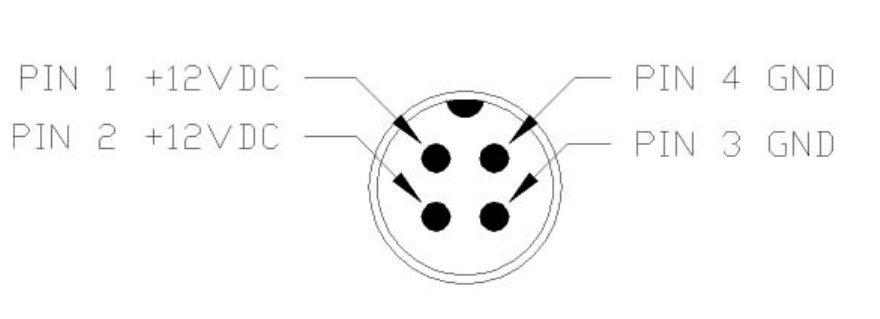
3.2.2.1 DC Power
The MCC-545C requires a power source that can deliver up to 25 amps of pulsed power (100
msec) out of a +12 VDC to +14VDC power source. The 25 amp power demand will cause a
voltage drop to occur at the transmitter input, resulting in reduced transmit power, unless the
power cable to the source is sized appropriately. MCC recommends using two #16 AWG wires
for both the power and ground and a cable length that does not exceed 10 feet. If a longer cable
is required use #14 AWG. MCC provides a standard 6 foot power cable with lugs for connecting
to a 3/8” battery post (Part No. 14001261-03).
The power connector pins are as follows:
The voltage drop at pins 1 and 2 should not drop by more than 2VDC during transmission.
3.2.2.2 VHF Antenna
Connect the antenna cable to the BNC RF connector. RG-223 may be used for cable lengths
under 20 feet. Use a double shielded cable (RG-214) for cable lengths up to 100 feet.
3.2.2.3 GPS Antenna (Optional)
An external GPS antenna is required if a GPS receiver is installed in the MCC-545C. Connect
the GPS antenna cable to the SMA connector on the front panel.
3.2.2.4 I/O Port
The 44 pin I/O connector on the front panel includes three RS-232 ports as one Data I/O port.
MCC provides a standard cable harness that breaks out these four ports as shown below:

DESCRIPTION 2-24
MCC-545C PACKET DATA RADIO
12/2000
MCC PART NO. 14001352-01
3.2.2.4.1 Operator Port
The Operator Port is normally connected to a local operator terminal. Use a standard RS-232
cable with a 9-pin male D connector.
OPERATOR PORT – 9S
Pin Signal
1CD
(tied to pins 4 and 6)
2Tx Data
(from MCC-545C)
3Rx Data
(to MCC-545C)
4DTR
(tied to pins 1 and 6)
5 Ground
6DSR
(tied to pins 1 and 4)
7RTS
(tied to pin 8)
8CTS
(tied to pin 7)
9 Not Used
I/O Port
(44 Pin)
Data I/O Port
(25 Pin)
Aux Port
(9 Pin)
Data Port
(9 Pin)
Operator Port
(9 Pin)

DESCRIPTION 2-25
MCC-545C PACKET DATA RADIO
12/2000
3.2.2.4.2 Data Port
The Data Port is normally connected to a data logger, GPS receiver or other serial input device.
Use a standard RS-232 cable with a 9-pin male D connector. Refer to Appendix B and C for
more information on interfacing to data loggers or other serial input devices.
DATA PORT – 9S
Pin Signal
1 Not Used
2Tx Data
(from MCC-545C)
3Rx Data
(to MCC-545C)
4DTR
(to MCC-545C)
5 Ground
6DSR
(from MCC-545C)
7RTS
(to MCC-545C)
8CTS
(from MCC-545C)
9 Ring Ind.
(from MCC-545C)
3.2.2.4.3 Auxiliary Port (AUX)
The AUX PORT is normally connected to a GPS receiver or other serial input device. Use a
standard RS-232 cable with a 9-pin male D connector. This port is also used for interfacing to
MCC test equipment (pins 6, 8, and 9).

DESCRIPTION 2-26
MCC-545C PACKET DATA RADIO
12/2000
AUX PORT – 9S
Pin Signal
1 Not Used
2Tx Data
(from MCC-545C)
3Rx Data
(to MCC-545C)
4 Not Used
5 Ground
6 Ant. Clock
(from MCC-545C)
7 Not Used
8 Ant. Dir.
(from MCC-545C)
9 Ant. Dir.
(from MCC-545C)
IMPORTANT
The AUX port connector has three extra pins (pins 6, 8, and 9) whose signals do not conform to
the RS-232 standard. These are for MCC test purposes and are not used at this time. These pins
will NOT interfere with a normal 3-wire RS-232 connector (pins 2, 3, and 5).
3.2.2.4.4 Data I/O Port
The Data I/O port is used as a general purpose Supervisory Control and Data Acquisition
(SCADA) interface requiring limited I/O in lieu of a full data logging capability. Use a mating
cable with a 25-pin male D connector for access to the various functions. For convenience, this
cable may be routed to a terminal block for interfacing to the various sensors and other external
devices.

DESCRIPTION 2-27
MCC-545C PACKET DATA RADIO
12/2000
Data I/O Pins FUNCTION
1 Optocoupled input #1 positive ( 500 ohm resistor)
2 Optocoupled input #1 return
3 Optocoupled input #2 positive ( 500 ohm resistor)
4 Optocoupled input #2 return
5 Optocoupled input #3 positive ( 500 ohm resistor)
6 Optocoupled input #3 return
7 Optocoupled input #4 positive ( 500 ohm resistor)
8 Optocoupled input #4 return
9 Ground
10 Relay Output #1 Normally Open (2Amp rating)
11 Relay Output #1 Common
12 Relay Output #1 Normally Closed (2Amp rating)
13 Relay Output #2 Normally Open (2Amp rating)
14 Relay Output #2 Common
15 Relay Output #2 Normally Closed (2Amp rating)
16 Ground
17 Analog Input #1 ( 0 to 5 V)
18 Analog Input #2 ( 0 to 5 V)
19 Analog Input #3 ( 0 to 5 V)
20 Analog Input #4 ( 0 to 5 V)
21 Analog Input #5 ( 0 to 5 V)
22 Analog Input #6 ( 0 to 5 V)
23 +5V Reference (10mA for sensor excitation)
24 +12V (0.5A maximum)
25 Detected RF Test Point

DESCRIPTION 2-28
MCC-545C PACKET DATA RADIO
12/2000
3.3 Power-Up Sequence
IMPORTANT
Before applying power to the MCC-545C check all connections between the MCC-545C and the
external equipment (power, antenna, operator terminal, GPS receiver and data logger).. Refer to
Section 3.2.2 for complete cabling instructions.
3.3.1 Power On
CAUTION
Disconnect the antenna cable until the unit ID has been set (see paragraph 3.3.2).
To power up the MCC-545C, apply +12VDC to the power connector.
NOTE
When the unit transmits it will draw up to 25 amps, therefore, review section 3.2.2.1 for cabling
to the power source. The voltage drop at the input connector during transmission should be less
than 2 VDC for proper operation of the unit.
The following message should appear on the operator terminal when power is applied:
12/23/00 16:54:10 POWER SHUTDOWN/FAIL OCCURRED.
01/02/01 12:54:44 POWER HAS BEEN RESTORED... RESUMING OPERATION.
+
If this message does not appear then the baud rate may not be set correctly in the operator
terminal. The default baud rate setting in the MCC-545C is 9,600 baud, 8 data bits, one stop bit
and no parity. This baud rate setting may be changed in the MCC-545C using the SETBAUD
and SAVE commands, as described in Chapter 4.
The default baud rate settings are stored in flash memory. However, it is possible to lose these
settings if the lithium battery has lost its charge after the MCC-545C has been sitting on the shelf
for an extended time period. In that event, a message similar to that shown below will appear
upon start-up.
METEOR BURST RADIO SUBSYSTEM MBCT
(c) Copyright 2000 Meteor Communications Corp.
All Rights Reserved
RF Modem S/W Part Number P1060-00-00 Version 6.25 12/19/00
The desired baud rate must then be entered using the SETBAUD and SAVE commands.

DESCRIPTION 2-29
MCC-545C PACKET DATA RADIO
12/2000
3.3.2 Entering the Unit ID
It is very important that the unit ID is entered correctly before transmitting. If the unit transmits
with the wrong ID it may conflict with another unit in the system and will result in data or
messages being misrouted or lost. In addition, the network topography and statistics will receive
incorrect data that will impair network performance. Use the ID Command to set the unit ID:
ID,nnnnn,mmmm{,aaaaa},INIT
where nnnnn is the unit ID, mmmm is the Master Station assignment and aaaaa is the initial
Master Station connectivity setting. Obtain these numbers from your network manager. The
MCC-545C will save the ID and reboot whenever the unit is powered up or reset.
3.3.3 Set and Verify the Tx/Rx Frequencies
The MCC-545A is programmed by a factory-trained technician to operate on a number of
authorized frequency channels. Once programmed, these frequencies can be selected by the
operator from a keyboard.
You can set or display the TX and RX frequencies using the following command:
FREQUENCIES, XXXX,YYYY
Where XXXX is the desired transmit frequency and YYYY is the desired receive frequency
Example: FREQUENCIES,4550,4550
This will select 45.50 MHz for both the transmit and receive frequency. Only those frequencies
that have been previously programmed into the unit at the factory can be selected.
Once the frequencies are selected, confirm that the synthesizer is “ON” and locked by entering
the following command:
SYNTHESIZER, ON
The unit will respond with
SYNTHESIZER, ON Locked or Unlocked
If the synthesizer returns an unlocked response, check the frequency command to ensure that the
proper frequencies have been entered.
NOTE
The MCC-545C will not transmit if the synthesizer is not locked.

DESCRIPTION 2-30
MCC-545C PACKET DATA RADIO
12/2000
3.3.4 RF Test
A very thorough RF test can be made by typing TEST[CR]. TEST causes the processor to turn
the transmitter ON and measures the forward and reverse RF power that is being transmitted. It
also measures the battery voltage under load and the antenna noise voltage.
The following response will be displayed on the operator terminal:
Syncs Xmits Acks pwr-fwd pwr-rev v-bat det-RF
XXXX YYYY ZZZZ AAAA BBBB CCC DDD
where: XXXX = # of sync patterns received from the master station.
YYYY = # of transmissions made by the MCC-545C.
ZZZZ = # of Acknowledgements received from master station.
AAAA = Forward power in watts. This should be greater than 80 watts.
BBBB = Reflected power in watts. This should be less than 5 watts.
CCC = Battery voltage under load (while transmitting). This should be greater
than 10.6 VDC.
DDD = Received signal strength in dbm. This will normally be the noise level
at the antenna.
Troubleshooting Suggestions
If the battery voltage is normal, the forward RF power should be at least 80 watts. If it is lower
than 80 watts check for proper cabling to the power source. (see Section 3.2.2.1).
If the reverse RF power is greater than 5 watts check the antenna and coaxial cabling for proper
installation.
If both the forward and reverse power are low, the transmitter may be automatically shutting
down due to an antenna VSWR greater than 3:1. Check the antenna and coaxial cabling for
proper installation.
This completes the power-up sequence of the MCC-545C. The unit is now ready for operation.
Refer to Chapter 4 for detailed operating instructions.

DESCRIPTION 2-31
MCC-545C PACKET DATA RADIO
12/2000
OPERATIONS 4-1
MCC-545C PACKET DATA RADIO
12/2000
4.0 OPERATIONS
This chapter covers the fundamental operating procedures of the MCC-545C and is functionally
divided into seven sections:
! Getting Started
! Station Operational Parameters
! Sending and Receiving Messages
! Data Logging
! Reporting Position Location
! Master Mode Functions
! Examining System Statistics
4.1 Getting Started
4.1.1 Command Entry and Editing
You must enter carriage returns after every command. A list of all the operator commands are
given in Table 4.2.
When a command is accepted, the operator terminal will print the system time. For a description
of printouts, see Appendix A.
Before you begin you should familiarize yourself with the special editing functions that you can
use when entering commands:
[DEL] Deletes last character entered.
[CTRL] Prints command line on next line down.
[CTRL]-R Repeats last command line
\X Removes current line from command buffer.
[CR], [LF] or [ENTER] Terminates line and causes the command entered to be executed.
4.1.2 Unit Name and Station ID
In command descriptions, the parameter "name" is the assigned Station name. The name is the
numeric Station ID. For more information on MCC-545C operation as either a Remote or Master
Station, refer to Section 4.2.1. Station IDs, represented by "nnnn", can be assigned as follows:
1 – 245 Master Station
256 – 4095 Remote
OPERATIONS 4-2
MCC-545C PACKET DATA RADIO
12/2000
Verify the ID is set correctly with the following command:
ID
If it is not correct, refer to section 3.3 for procedures to set it.
4.1.3 HELP Command
Information about many of the MCC-545C commands can be obtained via the HELP command.
Typing HELP with no parenthesis produces a single page display of the alphabetized command
list. Typing “HELP,command” provides a summary explanation of how to use that particular
command. For example, typing HELP,ASSIGN explains the format to use when you enter the
ASSIGN command, along with a brief description of the command's function.
4.1.4 System Time and Date
The system calendar is maintained during power outages. If the date and/or time shown is
incorrect the calendar can be initialized with the following commands:
DATE,mm/dd/yy
TIME,hh:mm{:ss}
The time of day maintained in the MCC-545C is transmitted to all Remote Stations keeping all
units in a network on the same time reference. If the time of day received at a Remote Station
differs by more than two minutes from the internal Remote clock, the Remote will set its clock to
the received time of day.
To properly manage time, each Master Station and Remote Station must know how its own time
zone relates to UTC and the system time. This relationship is established by relating its time
zone to known reference points. UTC is always referenced to GMT; however, system time can
be referenced to any desired time zone. The time zone offset is defined with the following
command:
TIME ZONE,UTC offset,system offset
4.2 Station Operational Parameters
In order for the MCC-545C to operate correctly in your network, it must be properly configured.
Configuration requirements will vary from application to application, therefore refer to your
systems manual or consult your systems manager for correct settings.
Use the commands described in this section to set the configuration as required. You may use the
CONFIG and ASSIGN commands to verify proper configurations have been set.

OPERATIONS 4-3
MCC-545C PACKET DATA RADIO
12/2000
Finally, enter the SAVE command to write the configuration into the EEPROM for non-volatile
storage.
4.2.1 Configuring the MCC-545C
Configuration parameters include the unit ID, the Master Station assignment, I/O port functions
and baud rates, transmit and receive parameters and network parameters. Commands which
allow you to display/modify the configuration are marked with an * in the command table.
Parameters or operational states set by these commands are retained and will determine the way
in which the MCC-545C will interact with other equipment at the site and with the
communications network.
Most configuration parameters can be viewed with the "CONFIG" and the "ASSIGN"
commands. You should use these commands to verify that the configuration is correct. If it is not
correct, use the appropriate command(s) to correct the configuration, then enter the "save"
command to write the configuration parameters into the EEPROM.
Saving and Restoring the Configuration - The Theory
To aid your understanding how the MCC-545C operational configuration is saved and restored it
is helpful to understand the hardware and design philosophy of the MCC-545C.
The MCC-545C is designed to operate unattended in a variety of environments where power
may be applied continuously or intermittently. The goal is for the unit to continue to operate
without loss of messages, data or configuration even if power is randomly turned on and off.
Therefore the software is designed to operate continuously, to save all operational information
when power is off and to resume operation from that point when power is restored.
To support this philosophy, the MCC-545C has three types of memory: PROM, RAM and
EEPROM. The PROM is non-volatile memory that has been programmed with the MCC-545C's
operational software. This software contains the initial values of all operational parameters. The
values are referred to as the "factory defaults" because they are programmed in the factory when
the unit is first manufactured. The PROM can only be modified by replacing this chip with one
programmed with the new data.
The RAM contains all the dynamic data for the MCC-545C. All data logger data, positional data,
and messages entered into the MCC-545C are stored in RAM. Also, all command parameters are
stored in RAM. But RAM is volatile and can only retain information while power is applied.
Turning off or disconnecting power will cause all RAM information to be lost. To prevent this, a
small internal NiCad battery is used to maintain power to the RAM when external power is off.
During normal operation, the MCC-545C software operates from the data and the parameters
that are stored in RAM. Unfortunately, there are always situations when the RAM data may be
lost or corrupted due to total discharge of the battery, software crash or operator error. Since we
do not want to lose our configuration data during these situations, we have a third type of
memory.

OPERATIONS 4-4
MCC-545C PACKET DATA RADIO
12/2000
The third type of memory is EEPROM. It is nonvolatile and retains data even when power is
removed. Special access is required to program the EEPROM therefore it is not easily corrupted.
The MCC-545C can retain a copy of all the programmed configuration parameters in EEPROM.
However, EEPROM is limited to 10,000 write cycles per memory location so the MCC-545C
only writes to EEPROM using two special commands - "ID" and "SAVE". Only values that
have changed are written into EEPROM. A validation checksum is saved in the MCC-545C to
verify its data is correct.
When the MCC-545C ships from the factory it programmed with the following default
configuration: the Operator Port (port 0) is set for 9600 baud, 8 data bits, 1 stop bit, no parity,
ASCII protocol and no flow control. This provides a known starting point for communicating to
the unit from a terminal or computer. From this starting point, the user can program the unit ID
and other operational parameters and then use the "Save" command to write them to EEPROM.
As soon as the parameters are entered they take effect.
CAUTION
Once the software is rebooted or restart due to a crash or failure of the battery backup RAM, all
changes will be lost unless they were previously saved in EEPROM.
Saving and Restoring the Configuration - The Operation
1. The software normally executes using the data and parameters stored in RAM. When the
unit is turned off, or power is disconnected, the RAM information will be maintained by
battery backup. When main power is restored the unit continues operation from RAM.
2. The RAM contents will be lost under the following conditions:
(1) if the Reboot command is issued
(2) the white Reset button (S1) is pressed
(3) the internal battery backup is disconnected (by removing jumper JP1 while external
power is off)
(4) the NiCad battery fails or
(5) the software crashes and restarts.
The software will detect these events and will then recopy the configuration values from
EEPROM back into RAM when operation is resumed.
3. The software will revert to the factory settings contained in the PROM if the contents of
the EEPROM become invalid.
The user should beware that it is possible to "get in trouble" using the configuration process. For
example, assume you accidentally set the protocol for the operator port to MSC. If you do not
have the ability to interface using MSC protocol you will immediately lose contact with the

OPERATIONS 4-5
MCC-545C PACKET DATA RADIO
12/2000
MCC-545C. You will no longer be able to issue commands. Power cycling will not help either
because your change will be retained in RAM, even through power cycling. However, you can
always recover by removing the lid on the MCC-545C and pressing the Reset button (S1). This
will reboot and restore the EEPROM settings.
Alternatively, assume you want to change the operator port to MSC. You connect in ASCII
protocol, command the change to MSC protocol, then switch you PC to also use MSC protocol.
Operation resumes and all is well. But do not forget to do a SAVE. If the software ever reboots,
it will revert back to ASCII. And remember, once you do the SAVE you are committed to MSC
protocol. The Reset button now reboots to MSC and there is no easy way back to the factory
default settings. You will need an MSC capability to command a change back to ASCII.
4.2.2 Selecting MCC-545C Remote/Master Operation
The MCC-545C can operate as either a Remote Station or as a Master Station. Use the DEVICE
command to select the mode you require.
For normal MCC-545C Remote Station operation, enter:
DEVICE,REMOTE
For MCC-545C operation as a Master Station, enter:
DEVICE,MASTER
NOTE
Additional MCC-545C commands are available when DEVICE,MASTER is selected. There is
no help for this command.
4.2.3 Selecting Network Parameters
MCC recommends using the given default network parameters (values that are set on power-up
or after reset). If you choose to change these parameters, first review the discussion in this
Section and in Section 4.8.5, then use the following commands to change to the desired settings:
SNP{,pname,value}
where "pname" is the network parameter and "value" is a limit dependent on "pname". The
"pname" parameters are as follows:
TTL – Time-to-live in minutes (default is 120 minutes); this is the time limit for a
message to reach its destination before it is deleted from the queue.
The time-to-live parameter input is truncated to a 10-minute boundary. If you
enter 60 through 69, the TTL for the next message will be 60 minutes. A resultant
value of 0 (parameter range 0 – 9) means the message will never time out.
OPERATIONS 4-6
MCC-545C PACKET DATA RADIO
12/2000
TTR – Time-to-retransmit in minutes (default is 20 minutes); i.e., the message is
retransmitted if it has not reached its destination within this time frame.
NUP – Neighbor-up threshold (default is 20 acquisitions); the number of times a Station
must hear from another Station within a one minute time interval before it
becomes a neighbor.
NDOWN – Neighbor-down threshold in minutes (default is 20 minutes); if there is no
communication with a neighboring Station within the set time, the route to that
neighbor is ignored. Setting NDOWN to 0 maintains the routing to the neighbor
indefinitely.
RDOWN – MASTER OPERATION ONLY - Remote-down threshold in minutes (default is
1,440 minutes); if there is no communication with a Remote Station within the set
time, the Remote is declared down and is removed from the Remote table.
Setting RDOWN to 0 keeps a Remote defined indefinitely.
OTL – Outstanding text limit (default is 20 texts); the number of messages a Station is
allowed to send to another Station without an end-to-end acknowledgment.
CONNP – MASTER OPERATION ONLY - Connectivity message precedence (default is 1
precedence); information on changes in the connectivity table is given highest
precedence (automatic feature).
ETEAP – End-to-end ACK message precedence (default is 0 [zero] precedence); the
acknowledgment of a message when it reaches its final destination is given
highest precedence.
HTO – History file timeout in minutes (default is 10 minutes); maintains information for
duplicate filtering.
TEXTL – MASTER OPERATION ONLY - Text size in segments (default is 32 segments).
FLOODP – MASTER OPERATION ONLY - Partial "flooding" precedence level (default is
A precedence). Messages of this precedence level and above are transmitted over
all routes of minimum length; messages below this precedence are not sent over
all minimum length routes, but are sent only over the routes where the shortest
transmit queues exist.
MBHOP – meteor burst link hop weight (default is 1 hop). Defines the number of network
hops to associate with a meteor burst Master Station link when determining the
minimum path to use in routing a message. MBHOP should be set high enough to
prevent a meteor burst Master Station link to be chosen over a line-of-sight
Remote to Remote link in a network that is predominantly line-of-sight.
INF – MASTER OPERATION ONLY - Infinity hop quantity (default is 8 hops).
Defines the width of the network in hops plus one to determine when connectivity
OPERATIONS 4-7
MCC-545C PACKET DATA RADIO
12/2000
to a node is broken. Should be as low as possible to minimize auto-connectivity
traffic in the network, but large enough to not erroneously flag nodes as being
offline.
RELAY – MASTER OPERATION ONLY - Relay function specification (default is ON).
Specifies whether the MCC-545C should act like a Remote in terms of relay
functionality (i.e., does not share connectivity table with other Masters.
DATAP – priority of data reports initiated at the MCC-545C (default is Y precedence).
When used in any data collection network, this setting defines the precedence of
data reports generated asynchronously by the equipment itself. Typically, it
should be lower than operator entered messages and commands.
4.2.4 Selecting the Burst Monitor
The MCC-545C has a unique meteor burst monitoring capability that allows monitoring the
number of characters received, the RF signal level and other parameters on each reception.
To turn on the burst monitor and to record statistics on a meteor burst link, type:
MON{,d{,r}}
The two optional parameters are designed to limit the printout. The burst monitor generates two
or three lines of printout for every burst. This could conceivably create hundreds of pages of
printout a day in a network environment. The first parameter is the duration character count
limit. Only meteors lasting long enough to deliver "d" characters will be monitored. The second
parameter is the received character count limit; if at least "r" characters are received on the burst,
a monitor line will be generated. The default values are 100 for "d" and 1 for "r". For example, to
limit the printout, but still receive some maintenance benefit from the monitor, enter:
MON,500,100
This will limit the printout to meteors that have a duration character count greater than 500, or a
received character count greater than 100. These parameters may be adjusted as desired.
The command MONOFF turns off the burst monitor.
4.2.5 Controlling the Hourly Statistics Report
By default, an hourly statistics report is generated on the maintenance terminal port on the hour.
This report consists of the same statistic reports generated by the BINS, MEM, and STAT
commands.
The hourly report can be disabled by entering the command:
HOURLIES,OFF

OPERATIONS 4-8
MCC-545C PACKET DATA RADIO
12/2000
The hourly report can be re-enabled by entering the command:
HOURLIES,ON
4.2.6 Scheduling MCC-545C Events
The SCHED command allows you to schedule automated command "events". An "event" simply
consists of giving one or more commands a trigger time. When the MCC-545C's real-time clock
reaches the trigger time, the scheduler invokes the command as though you had entered it from
the MCC-545C's operator terminal.
Two different types of time trigger options are provided for command scheduling: INTERVAL
and TIME. The INTERVAL trigger allows you to schedule a command to be invoked at periodic
intervals within a 24-hour time period; the TIME trigger allows you to schedule a command to
be invoked only once at a specified point within a 24 hour time period. The command schedule
list is restarted each time the real-time clock reaches midnight.
To display the current schedule list, enter:
SCHED
To add a new command to the schedule list, enter:
SCHED,type,time{OFFSET,time},command
where: type = INTERVAL or TIME
time = hours:minutes:seconds
OFFSET,hh:mm:ss = time offset from specified timeframe (optional)
command = any MCC-545C command (with parameters)
NOTE
The scheduler ignores certain commands due to their interactive nature. The MESSAGE
command is currently the only one ignored
To remove command event(s) from the schedule list, enter:
SCHED,DEL,xxx
where: xxx = ALL (erases entire schedule)
or
= schedule list number (removes single scheduled event from the schedule list)

OPERATIONS 4-9
MCC-545C PACKET DATA RADIO
12/2000
IMPORTANT
The MCC-545C currently supports up to 50 scheduled command events. The schedule list will
be erased if the system software re-boots (not to be confused with power failure recovery, which
will preserve the schedule list).
You can schedule several command events to trigger at the same time, however, you cannot
force one command to execute before or after another. After assigning command events to the
schedule, the order of commands displayed in the schedule list is the order in which the events
will trigger for any given trigger time (i.e., an event with a low schedule number occurs before
an event with a higher schedule number).
4.2.7 Setting Timeout Duration
There is one programmable time limit for the I/O port input on the MCC-545C. MCC
recommends using the pre-programmed default timeout parameter. If you choose to change the
timeout the time limits may be set by entering the number of seconds, from 0 to 32767. Enter a 0
to turn off the time limit.
Command Description
STT,secs The Set Teleprinter Timeout command sets the time limit for characters at the
maintenance terminal. Default is 60 seconds (1 minute).
4.2.8 Setting Frequencies
The FREQUENCIES command is used in systems using synthesized frequencies only (see
Section 2.7.4). To enable setting frequencies, you must first enter the following command to
identify the system as a frequency synthesized system:
SYNTH,ON
You can then display/set the TX and RX frequencies using the following command:
FREQ{UENCIES{,aaaa,bbbb}}
where: aaaa = Tx Frequency (e.g., 4053 for 40.53 MHz)
bbbb = Rx Frequency (e.g., 4153 for 41.53 MHz)

OPERATIONS 4-10
MCC-545C PACKET DATA RADIO
12/2000
IMPORTANT
The MCC-545C limits the usable frequency range to a 2 MHz bandwidth. If frequencies are to
be changed outside this bandwidth then hardware modifications must also be made to the MCC-
545C.
If the synthesizer is unable to establish phase-lock when the SYNTH,ON command is entered,
the MCC-545C will respond UNLOCKED to the request and turn off the TX key. It will try
once a minute thereafter to establish phase-lock. If it fails, the message Synthesizer unlocked
will be displayed; if it succeeds, the MCC-545C will respond LOCKED and turn on the TX key.
4.2.9 Defining Data Relays
The ambient noise conditions at a remote station site may sometimes be excessive and a poor
communication path to the Master Station will result particularly if the remote station is
operating in a meteor burst mode. To overcome this problem, another MCC-545C may be
placed in a nearby quiet location and used as relay station between the MCC-545C at the noisy
site and its master station. When used as a relay, the MCC-545C will concentrate the data
reports it receives from one or more neighboring remote sites and forwards the data to the Master
Station.
When used in the relay mode,, the MCC-545C must be defined as a Master Station. The relay
will then receive MCC-550C sensor data GROUP reports (see MCC-550C Operations Manual),
repackage them and forward them to the Master Station. A relay can handle a total of sixteen
GROUP reports. These reports can be in any combination; i.e., four groups from each of four
Remote units, one group from each of sixteen Remote units or any combination in between.
Substitution tables must be established in both the relay unit and also at the Master Station to
manage the relay function.
When a designated GROUP report is received at the relay, it will substitute its own ID and group
number in the report as defined in its substitution table and forward the data to a MCC-520B
Master Station using the MCC-550C RF format rather than the standard MCC-545C message
format. When the relayed data is received at the MCC-520B it reconstructs the original data
report based on its own substitution table and route the report as required.
The following command is used to define the entries in the substitution table for a relay unit:
SUBST,relay_id,relay_group,remote_id,remote_group
where: relay_id is the relay unit's ID
relay_group is the data group report number at the relay
remote_id is the originating Remote unit's ID
remote_group is the data group report number at the originating Remote unit

OPERATIONS 4-11
MCC-545C PACKET DATA RADIO
12/2000
4.2.10 Scaling A/D Readings
The MCC-545C automatically scales the readings from its A/D converter for operator use. The
readings that require scaling are battery level, detected RF and transmit power. The scaling
factors that are required for these readings will depend on the type of hardware used at the MCC-
545C site and are set by operator command using the SCALE command. The SCALE
commands are summarized in Table 4.1.
There are four values that need to be scaled depending on the equipment configuration at the site:
! Battery Voltage (used by the STAT/TEST commands)
! Detected RF in db (used by the MM command, meteor monitor and BINS command)
! Detected RF in microvolts (used by the STAT/TEST commands)
! Transmit power level (used by the STAT/TEST commands)
The required scaling factors are determined by the power supply used in the packet data radio.
The RXTYPE command translates the receiver calibration curves from detected RF (in db) to
microvolts. These are nonlinear and significantly different for the MCC-527 and MCC-543
receivers..
To apply the scaling factors, the TXPWR A/D value must first be squared and then multiplied by
the scaling factor in the table. For the other values, use the A/D reading directly and multiply by
the appropriate scaling factor.
MCC-545C SCALING FACTORS
PARAMETER 12V 36V 28V
BAT 0.0623 0.05 0.1749
DETRF 0.0188 0.1074 0.0188
TXPWR 0.000353 0.00116 0.000353
RXTYPE 527 543 527
TABLE 4.1
4.3 Sending and Receiving Messages
The MCC-545C is a packet data radio and therefore enables an operator to send and receive
messages to all nodes within the network.
The messages may be entered from an operator terminal that is connected to the OPERATOR
PORT of the MCC-545C. There are three basic message types: (1) free-form text messages, (2)
canned messages and (3) commands. The general format for all messages is shown below:
MESSAGE, R , dest 1, dest 2, …dest n
where: R = Message priority; A is highest, Z is lowest.
dest = ID of the station(s) to which the message will be sent.
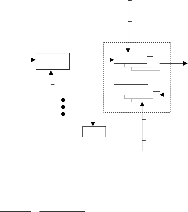
OPERATIONS 4-12
MCC-545C PACKET DATA RADIO
12/2000
Messages are first entered and edited in the TEXT EDIT BUFFER. They are then transferred to
one or more TX QUEUE buffers for transmission to the designated destinations. The diagram
below depicts the general flow of messages within the MCC-545C software and the various
commands associated with each step in the process.
MESSAGE FLOW AND ASSOCIATED COMMANDS
FIGURE 4.3
The following operations are explained in this section:
SECTION OPERATIONS
4.3.1 Entering and Deleting Messages
4.3.2 Editing Messages
4.3.3 Sending Messages
4.3.4 Sending Commands
4.3.5 Sending Canned Messages
4.3.6 Receiving Messages
4.3.7 Examining Message Status
4.3.8 Examining and Revising Message Queues
4.3.1 Entering and Deleting Messages
All messages are composed and edited in the TEXT EDIT BUFFER. Messages may be 3,570
characters in length. When composing the message press [CR] at the end of each 80 character
line.
TX QUEUE
PRINT
RX QUEUE
[SHOW]
[FLUSH]
[DEL]
[SMS]
[SHOW]
[FLUSH]
[DEL]
[SMS]
TEXT EDIT
BUFFER
[MESSAGE]
[CMD]
[CANMSG]
EDIT COMMANDS
[ESC]
[DEL]
[ESC]
TO/FROM
NEIGHBORING
STATIONS
ACK
END-TO-END

OPERATIONS 4-13
MCC-545C PACKET DATA RADIO
12/2000
There is a default destination programmed into the MCC-545C during the installation and
initialization of the unit when it is first brought on-line in the network. If a message is not given
a specific destination it will be sent to the default destination only.
To enter a message:
1. Type MESSAGE. The operator terminal will respond with ENTER TEXT. The MCC-
545C will now be in the compose and edit mode.
2. Enter a message up to 3,570 characters in length, pressing [CR] at the end of each 80
character line.
3. Press the [ESC] key. The message will now be transferred to a Tx queue and will be
automatically transmitted to the default destination at a priority level R.
The following message will be displayed, or printed, on the operator terminal:
hh:mm:ss Message No: name:ss,nnnn chars, nnn segments
hh:mm:ss ROUTING name :sss TXT sss/nn TO: name
If you wish to send a message to multiple destinations, and at a different priority level,
type
MESSAGE, R, dest1, dest2, …dest n
where: “R” is any priority level from A to Z. A is the highest and Z is the lowest.
“Dest” is the numerical ID of the stations to which the message will be routed.
NOTE
If you also want to send the message to your default destination you must enter its station
numerical ID as one of the destination parameters (“dest1”, “dest2”, etc.) as specified above.
NOTE
If you want to use source routing enter 0 for the destination ID. When the master station
receives this message it will send the message to the appropriate destination based on it’s link
table showing which destination(s) are linked with your station. Refer to the master station
manual for more information on source routing.
There are three other special editing functions that may be used:
1. To Retransmit A Previously Entered Message
To retransmit a previously entered message simply depress the [ESC] key after the
operator terminal prints ENTER TEXT and before any other key is depressed. The
previous message entered into the TEXT EDIT BUFFER will then be sent to the
destinations that are now designated in the MESSAGE command.

OPERATIONS 4-14
MCC-545C PACKET DATA RADIO
12/2000
2. To Revise A Previously Entered Message
To revise a previously entered message press [CTRL]T after the ENTER TEXT prompt
to revise a previously entered message or to recover from an aborted session. The
previous message will be displayed with the cursor placed at the end of the message.
You may now resume editing the message.
3. To Delete a Message
To delete a message after it has been placed in the Tx Queue, type
DELMSG, ID: sss
where: ID is the numerical station ID
sss is the message serial number
The operator terminal will print the date and time, followed by MESSAGE DELETED.
4.3.2 Editing Messages
The following editing functions may be used while the message is in the TEXT EDIT BUFFER.
KEY FUNCTION
[DEL] Deletes the last character entered.
[CTRL]R Prints the current line of text on the next line down.
[CTRL]I Performs a fixed tab function
\ Removes the current line from the edit buffer.
[CR] Performs a carriage return and line feed.
[LF] Performs a carriage return and line feed.
[CTRL]X Removes the current line from the edit buffer and places the
cursor at the end of the previous line.
[CTRL]T Prints the contents of the edit buffer.
[CTRL]D Erases the entire contents of the edit buffer.
[CTRK]A Aborts the edit mode and returns to the command mode.
A “+” indicates the command mode.
ESC Leaves text edit mode and queues the message for transmission.
4.3.3 Sending Messages
Messages are automatically transmitted with the [ESC] command. Each message will be placed
in the Tx Queue in accordance with its assigned priority. Messages of equal priority are placed
in the Tx Queue in the order received from the TEXT EDIT BUFFER.
The following display will appear on the operator terminal as the MCC-545C begins to transmit
a message:

OPERATIONS 4-15
MCC-545C PACKET DATA RADIO
12/2000
hh:mm:ss Message No: name:ss,nnnn chars, nnn segments
hh:mm:ss ROUTING name :sss TXT sss/nn TO: name
Messages are transmitted in packets and are routed to their destination in a store and forward
manner, using the most efficient routing within the packet switched network. The originating
station will receive an acknowledgement (ACK) if the message has been received successfully
by the first routing station.
mm/dd/yy hh:mm:ss TXTMSG ACK name:sss, xxxx CHARS FROM name
When the entire message has been delivered to its final destination an end-to-end
acknowledgement will be displayed on the operator terminal:
hh:mm:ss END-TO-END ACK OF name:sss FROM name
If the end-to-end ACK is not received within the specified time-to-live limit, the MCC-545C will
purge the message from the Tx Queue and display the following message:
hh:mm:ss MESSAGE TIME-TO-LIVE EXPIRED, MSG.NO:sss, DESTN: name
You must then reenter the message. Continued failure to successfully transmit a message
indicates that something may be wrong with the equipment or the link (e.g., excessive noise
interference).
4.3.4 Sending Commands
Commands may be sent to any remote station within the network. The entry of a command is
similar to the MESSAGE command described in Section 4.3.1.
REMCMD, R, dest1, dest2, …destn
where: R = priority level
dest = numerical ID of destination station(s)
The operator is then prompted to enter the text of the command using the message editor. Once
the command is entered, press the [ESC] key to send the command. The operator terminal will
display:
A response will be received from the destination station(s) if it was successfully received.
hh:mm:ss Message No: name:sss, nnnn chars, nnn
Destination ID
Messa
g
e Number
(
0- Number of
Number of 14-character
OPERATIONS 4-16
MCC-545C PACKET DATA RADIO
12/2000
4.3.5 Sending Canned Messages
The MCC-545C may be placed into a canned message mode for automatic transmission of a
repetitive message to an assigned neighboring station. In the canned message mode no more
than 25 messages may be placed into the Tx Queue at one time. You may either send an edited
text message or a message that is randomly generated from the alphabet.
To enter a canned message generated from the alphabet, enter:
CANMSG,id,msg length{,min.queue depth}
where “id” is the neighboring station ID, the message length is from 1 to 3000 characters and the
queue depth is from 1 to 25. The default queue depth is 5. Additional canned messages will be
injected if the number of canned messages in the queue falls below the minimum queue depth.
To enter an edited canned message, enter:
CANMSG,id
where “id” is the neighboring station’s ID. After composing your message press the [ESC] key.
The MCC-545C will automatically route up to 25 copies of the canned message to the
destination station.
Each canned message will be acknowledged by the selected neighboring station. No end-to-end
acknowledgement will be received.
To terminate the mode, enter:
CANMSG OFF,id
Canned messages are normally not printed at destination station. To print canned messages as
they are received, enter:
CANMSG MODE,PRINT
To turn off the print mode, enter:
CANMSG MODE,NO PRINT
4.3.6 Receiving Messages
When a new message is received it is announced by the following display:
hh:mm:ss RECEIVING name:sss TXT sss/nn FROM name ROUTED TO: name
The MCC-545C then generates an ACK of the message packet and transmits the ACK to the
neighbor from whom the message was received:

OPERATIONS 4-17
MCC-545C PACKET DATA RADIO
12/2000
hh:mm:ss TXTMSG ACK name:sss, nnnn CHARS FROM name
When the destination MCC-545C receives a complete message, it displays the following
message:
hh:mm:ss MSG RECEIVED name:sss, xxxx CHARS
text………………………………
**end-of-message**
where “name:sss” is the message serial number.
Messages are deleted as they are displayed or printed unless they are being forwarded to further
destinations.
4.3.7 Examining MESSAGE STATUS
The status of all messages may be examined while they are still in the Tx Queue. (Note: once
an ETE is received for a message it is deleted from the queue).
To examine a message, enter:
SMS {,ID}
4.3.8 Examining and Revising Message Queues
There are two types of queues for transmitting and receiving messages:
QUEUE NAME DESCRIPTION
TXQ
(Transmit Queue)
This queue is used for transmitting all messages. There is
a separate transmit queue for each neighboring station in
the network. For example, if you enter a message for
DEST1 That message is placed in DEST1’s transmit
queue.
RXQ
(Receive Queue)
This queue is used for all received messages. There is a
separate receive queue for each neighboring station in the
network. For example, to examine message statistics from
NODE5, examine the receive queue from NODE5.
To examine the contents of either queue, type:
SHOW TXQ,ID or SHOW RXQ,ID
You must specify the queue by entering the station ID. For example, SHOW TXQ,006 prints
statistics for all messages being transmitted to station 006.
OPERATIONS 4-18
MCC-545C PACKET DATA RADIO
12/2000
You can only examine the receive and transmit queues for neighbor stations in the network.
To delete the contents of the transmit and receive queues, you must specify the exact queue by
entering a station name:
FLUSH TXQ,id or FLUSH RXQ,id
For each message deleted, the terminal prints:
Id:sss unlinked {and deleted}
The “and deleted” text appears only if the message is not present in another queue. When all
messages have been deleted, the terminal prints:
queue flushed
To delete a specific message, enter:
DEL MSG,id:sss
The terminal prints:
Message deleted
To delete all messages from all queues, enter:
FLUSH MSG
For each message deleted, the terminal prints:
Id:sss deleted
Entering the FLUSH MSG command deletes all messages in all queues for every node of the
network, including connectivity and end-to-end acknowledgment messages.

OPERATIONS 4-19
MCC-545C PACKET DATA RADIO
12/2000
4.9 Command Reference List
MCC-545C COMMANDS
All implemented MCC-545C commands are listed in Table 4.2 alphabetically for ease of
reference. However, many commands are used in conjunction with others. These functional
groups are given below. You may also type HELP or HELP,COMMAND to receive an
explanation of any listed command. Command responses and unsolicited printouts are shown in
Appendix A.
STATION CONFIGURATION
COMMANDS STATUS
COMMANDS MESSAGE
COMMANDS
†*ASSIGN †RCT BINS CANMSG
*BRATE †REMOTE TYPE CLS CANMSG MODE
*CHECKIN †RXTYPE CONFIG CANMSG OFF
†CLOSE PORT SAVE *HOURLIES †COMPRESSION
†CONNECT †SCALE MEM DEL MSG
DATE †SCHED MODE DQE RXQ
*DESTINATION SERIAL †MON DQE TXQ
*DEVICE *SET BAUD †MONOFF FLUSH MSG
*DUTY CYCLE †*SNP †NETMON FLUSH RXQ
*FREQUENCIES *SOURCE RELAY STAT FLUSH TXQ
†HOST MODE †START *STAT TIME *HOLD
†*ID †STOP T MESSAGE
†LOGOFF †STT TEST *MSG
†LOGON †SUBST *PRINT
*LOS CHECKIN *SYNTH REMCMD
*MODULATION TIME
†NEW
PASSWORD †TIME ZONE POSITION LOCATION COMMANDS
†OPEN PORT *TXLIMIT †*POS †RED
†PASSWORDMO
DE †POSRPT †RTCM
MODE CONTROL COMMANDS MASTER SIMULATOR COMMANDS
†CORPAT †*HALF DUPLEX *P
*FULL DUPLEX †*ROLE
MAINTENANCE COMMANDS DUAL MASTER STATION COMMANDS
BOOT SHOW TXQ †SWCTL SWMON
RESET SMS
REV UPDT UTILITY COMMANDS
SHOW RXQ FLASH HELP
WARNING/WEATHER SYSTEM
COMMANDS DATA LOGGER COMMANDS
†FLOOD
TIMEOUT †SENSOR P77 SDATA

OPERATIONS 4-20
MCC-545C PACKET DATA RADIO
12/2000
†GLOF †STATION TYPE †$PENTM
†GLOF
MONITOR †WARNING
†HORN †WARNING
TIMEOUT
†PRIORITY †WEATHER
CR10X COMMANDS
CR10X CR10X,ORDER CR10X,SETPTR
†CR10X,ACQMODE CR10X,REGISTER CR10X,SIGNATURE
†CR10X,GROUP CR10X,RESET CR10X,STAT
†CR10X,INTERVAL †CR10X,SCALE †CR10X,TIME
CR10X,MAXQ CR10X,SECURITY CR10X,UPLOAD
MASTER MODE COMMANDS
*BASE NET STAT SHOW MAINTENANCE
MONITOR
CLEAR MAINTENANCE
MONITOR NET STAT PERIOD SHOW REMOTES
CONFIGURATION †POLL SHOW RXQ
LISTM PRG SHOW TXQ
LISTT REMOTE STAT SML
MM *REPEATER SMS
NET RX STAT TYPE
* Parameters/settings specified by these commands are stored in the EEPROM. Changes
specified by these commands take effect immediately but are lost when the unit is rebooted
unless the SAVE command is issued to write the changes to EEPROM. Changing the unit ID
automatically saves the entire configuration.
† Parameters/settings specified by these commands are stored in battery backed-up RAM.
Changes specified by these commands take effect immediately but are lost when the unit is
rebooted unless the SAVE command is issued to write the changes to BBU RAM; in addition,
the BBU jumper must be in place to enable RAM back-up.
If both symbols are present on a command, certain aspects are stored in one way and other
aspects are stored in the other. See command table below for clarification.

OPERATIONS 4-21
MCC-545C PACKET DATA RADIO
12/2000
MCC-545C COMMANDS
COMMAND DESCRIPTION PARAMETERS RANGE
†*ASSIGN
{,function,port,protocol
{,timeout}}
NOTE
function, port and protocol
information for ports 0, 1,
2 are stored in EEPROM;
this information for port 3
and all timeout information
is stored in BBU RAM.
Control allocation of user interface functions among
physical device channels. When no parameters are
entered, displays I/O configurations. Port definitions are
as follows:
Front Panel
Port Connector
0 OPERATOR PORT
1 DATA PORT
2 AUXILIARY PORT
3 DIAGNOSTICS PORT (Internal)
NOTE
It is possible to “lose control” of the MCC-545C
software by assigning control functions to ports with no
devices attached or by turning off control functions. For
example, if you turn off the Operator Port
(ASSIGN,MNT,OFF), you will not be able to enter
commands or view printouts from the MCC-545C. You
must open the MCC-545C and press the Reset button on
the microprocessor board to re-enable the Operator Port.
function = user
interface function
port = physical
device channel
protocol = link
level protocol
timeout in
seconds
MNT, POS, MSG,
ALT, DTA, C&S,
0-2, OFF
APCL5, ASCII,
CR10X,
DATALITE, ENAV,
FWS, GPS, GYRO,
IDA, IHS, MSC,
PHAROS, PKT,
RTCM, TM8T
0 – 32767
*BASE{,nnn,nnn} Set display range of Master Station IDs reserved for use
as Base Stations nnn = Master
Station ID
OFF = no Bases
2 – 245
BINS Print link distribution statistics
BOOT Cold start of Station software. All volatile memory is
lost.

OPERATIONS 4-22
MCC-545C PACKET DATA RADIO
12/2000
MCC-545C COMMANDS
COMMAND DESCRIPTION PARAMETERS RANGE
*BRATE,rate Set transmit bit rate in kilobits per second. There is a
low or high rate setting; effective rate at either setting is
based on the componentry installed in the bit clock
generator.
rate = 4K/4.8K or
8K/9.6K
CANMSG,nnnn (,msg
length {,min queue depth}) Automatically generate a message of specified length
that repeats until turned off with CANMSG OFF
command. You can compose the message by entering
only the destination name (not message length or
minimum queue depth). Destination node must be a
neighbor node. CANMSG cannot contain more than 25
messages in its queue. If the number of canned message
in queue falls below minimum queue depth, additional
canned messages will be injected.
nnnn = Station ID
Master = 1 –
4095
Remote = 256 –
4095
msg length =
number of
characters in
message
min queue depth
= min. # of
canned messages
in queue
1 – 4095
1 – 3000
0 – 25
CANMSG MODE
{,mode) Set reception of canned message to two of the following
states: PRINT – print all messages
NO PRINT – does not print messages
mode = PRINT
NO
PRINT
CANMSG OFF,nnnn Turn canned message mode off nnnn = Station ID
Master = 1 – 245
Remote = 256 -
4095
1 – 4095
*CHECKIN{,ii} Select check-in interval in seconds ii = interval 1 – 65535
CLEAR
MAINTENANCE
MONITOR
Clear monitor Station

OPERATIONS 4-23
MCC-545C PACKET DATA RADIO
12/2000
MCC-545C COMMANDS
COMMAND DESCRIPTION PARAMETERS RANGE
†CLOSE PORT,function
{,function,…} Close specified MCC-545C port from operation. You
can enter more than one port name to close, using
commas to separate the names on the same line.
CAUTION
The OPEN/CLOSE PORT commands directly affect
MCC-545C network activity and message flow. Do
NOT use these commands unless directed to do so.
function = user
interface function MNT, POS, MSG,
ALT, DTA, C&S
CLS Print current values, then clear link statistics (see STAT).
†COMPRESSION{,actio
n} Enable/disable data compression on outbound
messages/data reports. Intermediate nodes pass on the
information in compressed form. The destination
decompresses the information.
action =
ON – enable
OFF – disable
CONFIG Show current configuration parameters report.
NOTE
Configuration in EEPROM may differ unless the SAVE
command is used after configuration changes are made.
CONFIGURATION List major Master Station configuration settings.
†CONNECT,{nnn…} Limits Master-to-Master connectivity for lab and field
network configuration nnn = Master
Station
OFF = no
limitation
1 – 245
CORPAT Without parameters, display report of available
correlation patterns and indicate usage.

OPERATIONS 4-24
MCC-545C PACKET DATA RADIO
12/2000
MCC-545C COMMANDS
COMMAND DESCRIPTION PARAMETERS RANGE
†CORPAT,RX,action
{,pppp...} Define Receiver correlation patterns to recognize.
Pattern 1 is the default and is the only pattern recognized
if no others specified. Up to 16 pre-defined patterns are
recognized.
action = ON –
define patterns
or
OFF – use only
default pattern
pppp = pattern
number; ALL
means
recognize all
patterns
1 – 8
†CORPAT,TX,pppp
{,ALWAYS}Define Transmitter correlation pattern to send. Pattern 1
is the default and is the only pattern recognized if no
other specified. Up to 16 pre-defined patterns may be
used.
pppp = pattern
number
ALWAYS means
use specified
pattern instead
of received
pattern
1-- 8
CR10X Display CR10X configuration parameters
†CR10X,ACQMODE,mo
de Set CR10X acquisition mode - Get all reports since last
UPDT mode =
ALL – get all
reports since last
update
CURRENT –
get only the
current data
report
LAST,n – get
last “n” data
reports

OPERATIONS 4-25
MCC-545C PACKET DATA RADIO
12/2000
MCC-545C COMMANDS
COMMAND DESCRIPTION PARAMETERS RANGE
†CR10X,GROUP,source Specify source of data report group assignment. source =
545C – MCC-
545C assigns
group numbers;
CR10X internal
group number
matches data
array
CR10X –
CR10X assigns
group numbers;
MCC-545C gets
group number
from first sensor
†CR10X,INTERVAL,n Acquisition scan interval in seconds. OFF disables acq.
scan n = seconds 0 – 32767
CR10X,MAXQ,nnn Set maximum number of reports to queue for each scan
of the CR10X nnn = number of
reports 1 – 200
CR10X,ORDER,order Specify order of final storage data (currently only FIFO
is available). order =
FIFO – first in,
first out
LIFO – last in,
last out
CR10X,REGISTER,n{,dd
d} Read/Set internal storage register. n = register
number
ddd = value
1 – 28
Signed floating point
number (see CR10X
manual)

OPERATIONS 4-26
MCC-545C PACKET DATA RADIO
12/2000
MCC-545C COMMANDS
COMMAND DESCRIPTION PARAMETERS RANGE
CR10X,RESET Reset CR10X internal error counters to zero
†CR10X,SCALE,type Define sensor scaling type. type =
545C – data
scaled in integer
hexadecimal
units
CR10X – data
scaled in
Campbell
Scientific
floating point
format
CR10X,SECURITY,nnnn,
nnnn,nnnn Enter CR10X Internal Security Codes. See CR10X
manual. If CR10X program contains security codes, this
command (with correct security codes) must precede any
other command for CR10X to respond.
nnnn = security
code 0 - 9999
CR10X,SETPTR,DATE,
TIME Manual set up of last data pointer in the MCC-545C DATE = mmddyy
TIME = hhmm mm = 1 - 12
dd = 1 - 31
yy = 0 - 99
hh = 0 - 23
mm = 0 - 59

OPERATIONS 4-27
MCC-545C PACKET DATA RADIO
12/2000
MCC-545C COMMANDS
COMMAND DESCRIPTION PARAMETERS RANGE
CR10X,SIGNATURE Read and Display Current CR10X program signature.
The Signature is a checksum of program bytes. Signature =
checksum 0 - FF (hex)
CR10X,STAT Read and display CR10X internal pointers and error
statistics.
†CR10X,TIME,source Specify source of data report group timestamp. source =
545C – MCC-
545C assigns
timestamp
CR10X –
CR10X assigns
timestamp;
MCC-545C gets
timestamp from
second and third
sensors
DATE{,mm/dd/yy} Set system date. If no parameters are given, show
current date. If parameters are given, DOS calendar will
also be updated.
mm = month
dd = day
yy = year
1 – 12
1 – 31
0 – 99
DEL MSG,nnnn:sss Delete specified message. nnnn = Station ID
Master = 1 – 245
Remote = 256 –
4095
sss = message
serial #
1 – 4095
1 – 255
*DESTINATION{,nnnn...
.} Set default message/data destination(s). Enter 0 to use
source routing at the Master Station. If you turn off the
MCC-545C’s default destination, no data will be queued,
and the message editor will ask you to enter a destination
before sending a message. Up to four destinations may
be specified.
nnnn = OFF, 0 or
Station ID:
Master = 1 –
245
Remote = 256 –
4095
0 – 4095

OPERATIONS 4-28
MCC-545C PACKET DATA RADIO
12/2000
MCC-545C COMMANDS
COMMAND DESCRIPTION PARAMETERS RANGE
*DEVICE{,type} Select device type mode of operation (i.e., the MCC-
545C acts as a Remote or a limited Master Station). type =
REMOTE
MASTER
DQERXQ,nnnn:sss Delete specified message from the receive queue nnnn=Station ID
Master = 1 – 245
Remote = 256 –
4095
sss = msg serial
number
1 – 4095
1 – 245
DQETXQ,nnnn:sss Delete specified message from the transmit queue nnnn=Station ID
Master = 1 – 245
Remote = 256 –
4095
sss = msg serial
number
1 – 4095
1 – 245
*DUTY CYCLE
{,percent} Set transmitter duty cycle (default is 10%). Duty cycle
increases in increments of 5%. percent = 1 – 100 1 – 100
FLASH Initiate flash memory download. You must type a dozen
or so “f” characters after entering the command to cause
the bootstrap to take control and initiate the download
dialog.
†FLOOD TIMEOUT{,t} Display/set timeout period in minutes for the time after a
flood that the Stations are to report once a minute t = timeout in
minutes 1 – 1440
FLUSH MSG Delete all messages from all queues.
FLUSH RXQ,nnnn Delete all elements of specified Station from receive
queue. nnnn = Station ID
Master = 1 – 245
Remote = 256 –
4095
1 – 4095

OPERATIONS 4-29
MCC-545C PACKET DATA RADIO
12/2000
MCC-545C COMMANDS
COMMAND DESCRIPTION PARAMETERS RANGE
FLUSH TXQ,nnnn Delete all elements of specified Station from transmit
queue. nnnn = Station ID
Master = 1 – 245
Remote = 256 –
4095
1 – 4095
*FREQ{UENCIES}{,Tx,
Rx} Set operating frequencies of the MCC-545C/S.
Componentry in the MCC-545C/S limits the usable
frequency range to a 2 MHz bandwidth. If frequencies
are to be changed outside this bandwidth, hardware
modifications must also be made. The Frequency
Synthesizer must be enabled via the SYNTH,ON
command for FREQ{UENCIES} to have any effect.
This command is meaningless on an MCC-545C.
Tx = Tx
frequency in MHz
times 100
Rx = Rx
frequency in MHz
times 100
4000 – 5000
4000 – 5000
*FULL DUPLEX Set MCC-545C in full-duplex mode.
IMPORTANT
When set to full-duplex mode, the MCC-545C’s receiver
is disabled by the built-in Tx/Rx switch.
†GLOF{,nnnn,nnnn} Define the IDs for use as GLOF sensor Stations/display
total GLOF setup. nnnn = Station ID
Master = 1 – 245
Remote = 256 –
4095
OFF disables
GLOF sensor
Stations
1 – 4095
†GLOF
MONITOR,t,action Setup timeout (in seconds) and action for the GLOF
MONITOR Station t = timeout in
seconds
action = ALERT,
FLOOD
10 – 3600

OPERATIONS 4-30
MCC-545C PACKET DATA RADIO
12/2000
MCC-545C COMMANDS
COMMAND DESCRIPTION PARAMETERS RANGE
†*HALF DUPLEX{,n}
NOTE
Duplex state is kept in
EEPROM and probe
interval is kept in BBU
RAM.
Set Master Station to half-duplex mode and specify
number of milliseconds between idle probes. If no
parameter specified, last setting is used (default = 30).
n = milliseconds
between idle
probes
30 – 30,000
HELP{,command} Display help information on specified command. If no
parameter entered, all commands are sequentially
displayed in alphabetical order.
command = valid
MCC-545C
command
*HOLD Select message hold mode.
†HORN,function{,open,
close,on,off,duration} Defines horn timing setup function = TEST,
FLOOD,
STAGE 2,
STAGE3, ALL
CLEAR
open = valve
opening time
close = valve
closing time
on = on time
off = off time
duration = overall
duration for
on/off cycle
All times in seconds
1 – 15
1 – 15
1 – 3600
1 – 3600
1 - 3600

OPERATIONS 4-31
MCC-545C PACKET DATA RADIO
12/2000
MCC-545C COMMANDS
COMMAND DESCRIPTION PARAMETERS RANGE
†HOST MODE{,mode} Define host mode functionality in composite networks
when host link is not available. STOP = stop
transmitting if
host connection
lost
CONTINUE =
keep transmitting
if host
connection lost,
but set bit
flagging loss in
probe
OFF = ignore
host connection
state; keep
transmitting and
do not set bit
flagging loss in
probe
*HOURLIES{,action} Turn on/off hourly statistics. action =
ON – enable
OFF – disable

OPERATIONS 4-32
MCC-545C PACKET DATA RADIO
12/2000
MCC-545C COMMANDS
COMMAND DESCRIPTION PARAMETERS RANGE
If device – Remote:
Normal operation
†*ID{,nnn,mmm{,mode}
{,INIT}}
NOTE
Remote and Master IDs are
kept in EEPROM and
mode is kept in BBU
RAM.
Set MCC-545C’s assigned Master Station ID to number
“nnn”. When no parameters are given, current ID is
displayed. When system is already initialized, you must
enter the INIT parameter to change ID. INIT gives
“OK” to save configuration and reboot unit with new ID.
ID changes are automatically saved with the entire
configuration in EEPROM. “mode” parameter (if used)
specifies initial connectivity with specified Master.
PREF means Remote considers connectivity established.
AUTO means no connectivity established. FIXED
(Default) means connect only with specified Master.
NOTE
If command does not change the ID or Master Station,
the SAVE and reboot are not performed.
nnn = Remote ID
mmm = Master
ID
mode = PREF,
AUTO or
FIXED
256 – 4095
1 – 245
†ID,mode Change " mode" as discussed above without affecting ID;
no reboot performed. mode = PREF,
AUTO or FIXED
If device = Master:
*ID{,nnn{,INIT}} Set MCC-545C’s assigned Master Station ID to number
“nnn”. When no parameters are given, current ID is
displayed. When system is already initialized, you must
enter the INIT parameter to change ID. INIT gives
“OK” to save configuration and reboot unit with new ID.
ID changes are automatically saved with the entire
configuration in EEPROM.
CAUTION
If you enter INIT, you will lose all current message
information.
nnn = assigned
Master ID 1 – 245

OPERATIONS 4-33
MCC-545C PACKET DATA RADIO
12/2000
MCC-545C COMMANDS
COMMAND DESCRIPTION PARAMETERS RANGE
LISTM{,nnnnn…} Display Remotes with burst monitor bit set (all Remotes
or given IDs up to 12). nnnnn = Station
ID
Master = 1 –
245
Remote = 256 -
4095
1 – 4095
LISTT{,nnnnn} Display Remotes with “Type” flag set (all Remotes or
given IDs up to 12) nnnnn = Station
ID
Master = 1 –
245
Remote = 256 -
4095
1 – 4095
†LOGOFF Used to disallow operator commands with automatic 10
minute timeout for LOS role and 60 minute timeout for
TRANSPOND role. Logs you off, disables ALL
following operator commands except LOGON,
$PENTM, or SDATA.
†LOGON,password LOGON used to allow operator commands. To log onto
a unit, enter the LOGON command followed by the
current password. This will remain in effect for a timeout
period (10 or 60 minutes depending on operating mode),
or until you log off. Default = MCC-545C
password = 3-20
character
password
A-Z, 0-9, -
*LOS CHECKIN{,ii,rr} Select check-in interval (in seconds) and retry count for
LOS operation. ii = interval
rr = retry 1 – 65535
1 – 65535
MEM Show usage of dynamic pool memory.

OPERATIONS 4-34
MCC-545C PACKET DATA RADIO
12/2000
MCC-545C COMMANDS
COMMAND DESCRIPTION PARAMETERS RANGE
MESSAGE
{,p{,dest1…destn}} Enter a message with text editor. Message priority and
destination are optional parameters. After entering
message, press [ESC] to queue for transmission. If you
do not enter a destination ID, the MCC-545C
automatically sends your message to its default
destination (set with the DESTINATION command). If
you want to use source rounting, enter 0 for the
destination.
p = priority
dest1. . .destn =
destination(s)
name = node
name
nnnn = Station ID
Master = 1 –
245
Remote = 256 –
4095
A – Z, 0 – 9
A – Z, 0 – 9
1 – 4095
MM Print current value of RF signal on Receiver
MODE Print operating mode information.
*MODULATION,degree,
encoding Set the transmit modulation and data encoding.
IMPORTANT
545C modulation must be the same as other units in the
network.
degree = 90 or 30
encoding = MAN
for Manchester,
DIFF for
differential
†MON{,d{,r}} Turn on burst monitor. Only meteors lasting long
enough to deliver “d” characters will be monitored. If at
least “r” characters were received, a monitor line is
generated.
d = duration
character count
limit
r = received
character count
limit
0 – 32767
0 – 32767

OPERATIONS 4-35
MCC-545C PACKET DATA RADIO
12/2000
MCC-545C COMMANDS
COMMAND DESCRIPTION PARAMETERS RANGE
MONITOR{action{,nnn
{,nnn,…,nnn}}} Control monitoring of individual units and print burst
statistics. Overrides MONOFF command and causes
monitor lines to print for each reception from this unit.
action =
ON – enable
OFF – disable
nnn = units to be
monitored
ALL – default
Master = 1 –
245
Remote = 256 -
4095
1 - 4095
†MONOFF Turn off burst monitor
*MSG Display and delete top operator message in receive queue
when message HOLD is enabled.
NET Display network routing table for all selected neighbors.
NET – no neighbors
NET1,2 – 1,2, etc. neighbors
NET,all – all neighbors
NET STAT Display network statistics. Statistics accumulate from
the beginning of each hour and are cleared at the end of
the hour.
NET STAT
PERIOD{,minutes} Enable display of network statistics and set period
between displays (in minutes). Disable display by setting
period to zero (0).
Minutes =
number of
minutes between
each display
0 - 32767
NEWPASSWORD,old
password, new password Used to change the password. The NEW PASSWORD
command is used to change the internal stored password.
You must be logged on and know the old password. The
password will automatically be saved.
password = 3-20
character
password
A-Z, 0-9, -

OPERATIONS 4-36
MCC-545C PACKET DATA RADIO
12/2000
MCC-545C COMMANDS
COMMAND DESCRIPTION PARAMETERS RANGE
†OPEN PORT Resume activity on specified closed port. You can enter
more than one port name to open, using commas to
separate the names on the same line.
CAUTION
The OPEN/CLOSE PORT commands directly affect
MCC-545C network activity and message flow. Do
NOT use these commands.
function = user
interface function MNT, POS, MSG,
ALT, DTA, C&S
*P{,?}{,xxx}{,OFF} Configures MCC-545C for pulse probe mode. If no
parameters are entered, transmit single pulse probe.
Enter transmit single pulse probe. Enter P,? to display
current pulse probe mode settings. Enter P,xxx to send a
single periodic probe once every “xxx” seconds. Enter
P,OFF to turn off periodic pulse mode (you can still
transmit single pulses with P).
? = current
settings
xxx = periodic
pulse period (in
seconds)
OFF = turn off
periodic pulse
mode
P77 The P77 command must be used to place the Julian date
into position one, and Hour/Minute into position two.
With this setup, the MCC MCC-545C will strip off the
first two sensor values and place the date and time
derived from these values into the standard MCC 550B
report.

OPERATIONS 4-37
MCC-545C PACKET DATA RADIO
12/2000
MCC-545C COMMANDS
COMMAND DESCRIPTION PARAMETERS RANGE
†PASSWORDMODE,acti
on, password Used to enable/disable use of passwords. Default is
disabled. To enable or disable the operation with
passwords, enter this command giving the desired action
along with the current password for the unit. This will
trigger an automatic "save" operation. If set to the ON
mode, the state of the unit will be set to "logged-off". All
operator and remote commands except scheduled
commands, $PENTM commands, and SDATA
commands will respond with "ACCESS DENIED!".
You will not be able to turn off the mode without first
logging on.
action =
ON – enable
OFF – disable
password = 3-20
character
password
A-Z, 0-9, -
$PENTM Without parameter string, display report of current Entek
MDP configuration.
†$PENTM,
ALERTEVENTS{,mask} Set bit mask indicating Entek MDP status bits regarding
as alarms. Status bits are checked against this mask on
intercepted position reports and an alert message is sent
to the local MNT and DTA ports for each match.
mask =
hexadecimal bit
mask
0 – FFFF
†$PENTM,ALERTMSG
S {,nnn...} Define canned messages constituting an alert. Any
number may be defined (up to 10 per line). Intercepted
messages matching one of these numbers cause an alert
message to be sent to the local MNT and DTA ports.
nnn = canned
message number 1 – 120
$PENTM,command string Send command string to local Entek MDP. command string =
any valid Entek
MDP command
string
†$PENTM,action Enable/disable Entek MDP interface. When enabled,
allows communication with mobile data processor in
vehicle tracking applications and causes received status
bits from the MDP to be included with the position data
in the Remote's data reports.
action =
ON – enable
OFF – disable

OPERATIONS 4-38
MCC-545C PACKET DATA RADIO
12/2000
MCC-545C COMMANDS
COMMAND DESCRIPTION PARAMETERS RANGE
†POLL{interval,offset,
duration,retry}{,ALWAYS
}
Define/display polling schedule for Base/Repeater
Station. If ALWAYS parameter specified, do not
timeout on-line units (i.e., ignore retry count in this case).
interval = polling
interval in
seconds
offset = offset
from top of
minute
duration = length
of poll
retry = retry count
for failed polls
1 – 86400
1 – 59
1 – 10
1 – 99
*POS{,interval,format,
protocol} Display/initialize internal MCC-545C timing for
reporting GPS position data. Specify update period in
seconds, in either binary or text format, using given
protocol.
interval =
reporting interval
in seconds
format = display
format
protocol = GPS
unit protocol
0 – 65535
BINARY, TEXT
NMEA, ARNAV,
TAIP, TRANSAS
†POS,LOCAL{,interval} Display/initialize timing for local output of position
reports on MNT and DTA ports as well as sending them. interval =
reporting interval
in seconds; OFF
disables local
output
1 – 86400

OPERATIONS 4-39
MCC-545C PACKET DATA RADIO
12/2000
MCC-545C COMMANDS
COMMAND DESCRIPTION PARAMETERS RANGE
†POSRPT{,action} Enable/disable echoing of intercepted position reports to
local MNT and DTA ports. Also used to enable/disable
duplicate filtering and control format of these reports.
action =
ON – enable
OFF – disable
DUPL,ON –
enable
duplicate
filtering
DUPL,OFF –
disable
duplicate
filtering
FORMAT,LON
G – output
report on two
lines
FORMAT,SHO
RT – output
report on one
line
PRG,nnn Undefine MCC-545C Station from network. nnn = Master
Station ID 1 - 245
*PRINT Enable messages to print as they are received.
†PRIORITY,message
type,p Define priority characters for each message type. message type =
FLOOD,
ALERT,
ROUTINE
p = priority A – Z, 0 – 9

OPERATIONS 4-40
MCC-545C PACKET DATA RADIO
12/2000
MCC-545C COMMANDS
COMMAND DESCRIPTION PARAMETERS RANGE
†RCT{,action} Display/set remote control terminal functionality. This
functionality is applicable to Packet protocol systems
only and controls whether the unit ignores intercepted
data reports. If enabled, intercepted reports are ignored.
action =
ON – enable
OFF – disable
RED Without parameters, generates report of current RED
setup.
†RED,ID,nn-nnn Enables reception of remote emergency indications from
an MCC Remote Emergency Device (RED). The entered
ID code is used with RED messages generated by the
MCC-545C using RED,TEST or RED,TX.
nn = call sign
prefix
nnn = call sign
suffix
0 – 99
0 – 999
†RED,NUM,n Set dead-band interval in which repeated RED
activations do not generate another alert message. n = dead-band
interval in
seconds
1 – 120
†RED,OFF Disable reception of remote emergency indications from
an MCC Remote Emergency Device (RED).
RED,TEST Simulate a RED test message. Unlike a true RED test
button depression, this message is also echoed to the
local MNT and DTA ports.
RED,TX Simulate a RED alert message. Unlike a true RED alert
button depression, this message is also echoed to the
local MNT and DTA ports.

OPERATIONS 4-41
MCC-545C PACKET DATA RADIO
12/2000
MCC-545C COMMANDS
COMMAND DESCRIPTION PARAMETERS RANGE
REMCMD
,p,dest1{,…destn} With the text editor, enter a command to be sent to a
Remote. After entering command, press [ESC] to send
the command.
p = priority
dest1…destn
destination(s)
name = node
name
nnnn = Station
ID
Master = 1 –
245
Remote = 256 –
4095
A – Z, 0 – 9
A – Z, 0 – 9
1 – 4095
REMOTE
STAT{,nnnnn…} Display transmit/receive statistics for all Remote Stations
or for given IDs (up to 12). nnnn = Station ID
Master = 1 –
245
Remote = 256 –
4095
1 – 4095
†REMOTE
TYPE{,aaaaa} Display/set communication characteristics of the unit.
Determines how certain statistics are reported and how
remote commands/messages are framed.
aaaaa =
COMM
DATA
PACKET
*REPEATER{,nnn} Define/display Base Station to which the Repeater site
repeats. nnn = Base
Station ID
OFF clears a
previously
established
definition
1 – 245
RESET Perform hardware reset to clear and reinitialize I/O
channels and RF controller. This command retains
previous network configurations and message traffic.

OPERATIONS 4-42
MCC-545C PACKET DATA RADIO
12/2000
MCC-545C COMMANDS
COMMAND DESCRIPTION PARAMETERS RANGE
REV Display part and revision numbers of current Link
Controller and Tx/Rx Controller software.
†*ROLE{,role{,low,high}
{,mode}}
NOTE
Role is kept in EEPROM
and low, high and mode
are kept in BBU RAM.
Define role played in network, either SILENT (never
transmits), TRANSPOND (responds to probes), PROBE
(actively probes), or LOS (line of sight) mode. If role is
set to TRANSPOND, the low and high parameters can
be used to specify the threshold values for automatic
meteor burst vs. line of sight modes of operation and the
mode parameter can set the starting mode (meteor burst
or line of sight).
Thresholds are specified in idle probes per minute. To
prevent LOS operation altogether, set the low threshold
to 1000 if the unit’s Master is half duplex or 5500 if it is
full duplex.
role = SILENT,
LOS,
TRANSPOND
or
PROBE
low = threshold
for switching
from LOS to
MB mode in idle
probes per
minute
high = threshold
for switching
from MB to
LOS mode in
idle probes per
minute
mode = MB or
LOS
0 – 32767
0 – 32767
†RTCM{,nnn} Define time latency in seconds between beacon receiver
and local time. Without parameter, display report of
satellites in view by beacon receiver.
nnn = latency in
seconds 0 – 59
RX STAT{,CLEAR} Display statistics for the MCC-545C Receiver CLEAR = clear
all statistics after
display
SAVE Save CONFIG parameters in EEPROM. Reboot of
MCC-545C (or restart due to software failure) returns
unit to configuration saved in EEPROM.

OPERATIONS 4-43
MCC-545C PACKET DATA RADIO
12/2000
MCC-545C COMMANDS
COMMAND DESCRIPTION PARAMETERS RANGE
†SCALE{,parameter,value
}Display set A/D scaling factors for the unit. Factors
depend on type of receiver and power supply used in the
MCC-545C.
parameter =
BAT – battery
voltage
DETRF –
detected RF
TXPWR –
transmit
power
value = scale
factor
†SCHED{,basis,hh:mm:ss
{,OFFSET,hh:mm:ss},
command string}
IMPORTANT
SCHED ignores the
MESSAGE command. Up
to 50 events can be
scheduled.
Schedule execution of the specified command string. If
timeframe basis = INTERVAL, the command string will
be executed whenever the specified time interval elapses
during the day. If timeframe basis = TIME, the
command string will be executed at the specified time.
The OFFSET option allows specification of an offset
from the timeframe basis.
basis = TIME or
INTERVAL
hh - hours
mm - minutes
ss - seconds
0 – 23
0 – 59
0 – 59
†SCHED,DEL,nn Delete specified schedule item number. If nn = ALL, the
entire schedule will be cleared. nn = schedule
item number 1 – 50
SDATA,g,c,time stamp,
value... Enter an MCC-550C data report directly from the serial
I/O port. Up to 16 values may be entered. Use the
LINK command to route the data.
g = group number
c = sensor count
time stamp =
mmdddhhmn
value = ASCII
hex sensor value
1 – 4
1 – 16
mm 1 – 12
ddd 1 –365
hh 0 – 23
mn 0 – 59
0 – FFFF

OPERATIONS 4-44
MCC-545C PACKET DATA RADIO
12/2000
MCC-545C COMMANDS
COMMAND DESCRIPTION PARAMETERS RANGE
†SENSOR{function}
{weight}{low,high}}} Defines the GLOF sensor data limit for fail/dry/wet
determination. Gives the “weight” (i.e., how significant)
of each case for the flood calculation.
Function:
DRY
WET
FLOOD
FAIL
LOW 1 - 99
HIGH 1 – 9999
WEIGHT 1 - 99
SERIAL{,sss} Set next packet serial number. Parameter “sss” is serial
number of last packet transmitted. sss = message
serial number 1 – 255
*SET BAUD
{,function,rate,flow} Adjust baud rate and flow control of specified port.
When no parameters are entered, this command displays
I/O configurations.
function = user
interface
function
rate = baud rate
flow = flow
control
MNT, POS, MSG,
ALT, DTA,
CANDS,
110, 150, 300, 600,
1200, 2400, 4800,
9600
Y or N
SHOW REMOTES Display ID and assigned 520B of each Remote in system.
SHOW RXQ,nnnn Display contents of receive queue for the originating
Station. nnnn =
originating
Station ID
Master = 1 – 245
Remote = 256 –
4095
1 – 4095
SHOW TXQ,nnnn Display contents of transmit queue for the destination
Station. nnnn =
destination
Station ID
Master = 1 – 245
Remote = 256 –
4095
1 – 4095

OPERATIONS 4-45
MCC-545C PACKET DATA RADIO
12/2000
MCC-545C COMMANDS
COMMAND DESCRIPTION PARAMETERS RANGE
SML{,nnnn} Display names and serial numbers of message packets in
specified message list. If parameter is not entered, all
message packet names and numbers are displayed.
nnnn =
destination
Station ID
Master = 1 – 245
Remote = 256 –
4095
1 – 4095
SMS{,nnnn} Display status of message packet in specified message
list. nnnn = Station ID
Master = 1 – 245
Remote = 256 –
4095
1 – 4095

OPERATIONS 4-46
MCC-545C PACKET DATA RADIO
12/2000
MCC-545C COMMANDS
COMMAND DESCRIPTION PARAMETERS RANGE
†*SNP{pname,value}
NOTE
Some network parameters
are only for use in Master
Operation mode
(RDOWN, CONNP,
TEXTL, FLOODP, INF,
RELAY).
NOTE
TTL, TTR, NUP,
NDOWN, RDOWN,
OTL, HTO, TEXTL,
CONNP, ETEAP,
FLOODP, RELAY and
INF are kept in EEPROM;
DATAP and MBHOP are
kept in BBU RAM.
Set network parameters. See range column for values
entered for each parameter. pname – TTL
time-to-live
TTR time-to-
retransmit
N UP neighbor
up
N DOWN
neighbor down
R DOWN
Remote down
OTL outstanding
text limit
CONNP
connectivity msg.
precedence
ETEAP End-to-
End ACK
precedence
HTO history file
timeout
TEXTL text size
in segments
FLOODP partial
flooding prec.
level
INF infinity hop
quantity
DATAP priority
of data reports
created by MCC-
545C
0 – 2550 min.
(truncated to 10 min.
bndry)
default = 120
0 – 255 min.
default = 20
1 – 255 acq.
default = 20
1 – 255 min.
default = 20
0 – 32767
default = 1440
1 – 255
default = 20
0 – 9, A – Z
default = 1
0 – 9, A – Z
default = 0
1 – 255 min.
default = 120
5 – 255
default = 32
A – I
default = A
2 = 255 hop
default = 8
A – Z
default = Y
1 – 99
default = 1
ON, OFF

OPERATIONS 4-47
MCC-545C PACKET DATA RADIO
12/2000
MCC-545C COMMANDS
COMMAND DESCRIPTION PARAMETERS RANGE
*SOURCE
RELAY{,nnnn} Specify source routing table of one entry. The
designated Station will receive all information sent
without an explicit destination specification. If set to
OFF, such information is discarded.
nnnn = Station ID
Master = 1 – 245
Remote = 256 –
4095
†START Turn transmitter on.
STAT Display RF statistics report.
*STAT TIME{,xx} Set interval (in hours, starting at midnight) when MCC-
545C automatically transmits statistics to Master Station. xx = interval 1 – 24 hours
†STATION
TYPE{,aaaaa} Display/set special Station functionality. Determines
how each Station responds to the messages it receives
and limits the type of messages that can be created.
Meaningful only in Flood Warning and Maritime
Weather Systems.
aaaaa =
OFF
FLOOD BASE
FLOOD
WARNING
GLOF
SENSOR
GLOF
MONITOR
GLOF
WARNING
RELAY
STREAM
GAUGE
SYSTEM
MONITOR
WEATHER
†STOP Turn transmitter off.
†STT,secs Set command timeout (in seconds). Default is 15
seconds. secs = time limit
before reset (0-
off, >0-on)
0 – 32767

OPERATIONS 4-48
MCC-545C PACKET DATA RADIO
12/2000
MCC-545C COMMANDS
COMMAND DESCRIPTION PARAMETERS RANGE
†SUBST,rrr,g1,nnn,g2 Substitute Remote unit information in data reports
received from a relay unit. rrr = relay ID
g1 = relay grp#
nnnn = Remote
ID
g2 = Remote grp#
1 – 245
0 – 15
256 – 4095
1 – 4
†SUBST,DEL,ALL Delete entire substitution table
†SUBST,DEL,rrr,g1 Delete entry in substitution table rrr = relay ID
g1 = relay grp# 1 – 245
0 – 15
†SWCTL,OFF Disables the monitoring and switching function.
†SWCTL,ON,timeout,star
t delay When the software boots up from a reset state, it will test
the two RS-232 ports to determine which one is currently
active, assuming the switch may have been manually
controlled while it was off. From then on, it monitors the
two Masters assuming the primary Master (1) is
connected to the DTA port, and the Secondary Master
(2) is connected to the ALT port.
timeout =
inactivity time in
seconds resulting
in switchover.
start delay =
interval in
seconds after
starting before
monitoring
Master Stations.
1 – 32767
1 - 32767
SWCTL,SW,n Switch to designated Master Station switch position. n = switch
position 1 - 2
SWMON Monitors both the RS-232 port and RF link. This
SWMON command should be placed in the schedule of
the MCC-545C at an interval that detects a Master
Station failure within the required system design. There
are no parameters.
A typical example is: SCHED,I,5:0,SWMON

OPERATIONS 4-49
MCC-545C PACKET DATA RADIO
12/2000
MCC-545C COMMANDS
COMMAND DESCRIPTION PARAMETERS RANGE
*SYNTH{,action} Display/set status of frequency synthesizer. This
command is applicable only to the MCC-545C/S. action =
ON – enable
OFF– disable
TShow current date/time.
TEST Send test transmission and return updated statistics (uses
same format as STAT command).
TIME{,hh:mm:ss} Set system time. If no parameters are specified, show
current time. If parameters are given, DOS calendar will
also be updated.
hh – hours
mm – minutes
ss – seconds
0 – 23
0 – 59
0 – 59
†TIMEZONE{,UTC,sys} Set local time zone offsets from UTC time (GMT) and
system time. UTC = offset
from GMT
sys = offset from
system time
-12 – 12
-12 – 12
TRACE,action,data stream Diagnostic command used to enable/disable detailed
analysis of the specified data stream. action =
ON – enable
OFF – disable
date stream = RF,
GPS, MSC,
RTCM
*TX LIMIT{,count} Set limit on number of transmissions allowed in a 15-
minute period (in minutes). count = # of
transmissions
period = minute

OPERATIONS 4-50
MCC-545C PACKET DATA RADIO
12/2000
MCC-545C COMMANDS
COMMAND DESCRIPTION PARAMETERS RANGE
TYPE{,action{,nnn{nnn,
…
,nnnn}}}
Control auditing of messages entered at specified units
and routed through the MCC-545C. action =
ON - enable
OFF - disable
nnn = units to be
audited.
ALL – default
Master = 1 –
245
Remote = 256
– 4095
1 - 4095

OPERATIONS 4-51
MCC-545C PACKET DATA RADIO
12/2000
MCC-545C COMMANDS
COMMAND DESCRIPTION PARAMETERS RANGE
UPDT{,function,parameter
s} Send update message to data logger type device. NOTX: Read
sensors but do
not transmit data
read
TX: Read
sensors and
transmit data
read
TIME: Set time
of MCC-545C in
logger
TEST: Operate a
component in
test mode:
ALERT
FLOOD
HORN
GATE
WARNING
OUT: Set output
register:
BYTE
BIT,BITNU
MBER
BITS,START
BIT,
ENDBIT
ARM: Enable
alarm activation
DISARM:
Disable Alarm
activation
RESET: Reset
alarm condition
RM: Routine
message format
RMP:RMP
Message format
value appropriate to
the register:
0 – 255
1 – 8 (bit); 0 - 1
1 – 8 (bits); 0 - 255

OPERATIONS 4-52
MCC-545C PACKET DATA RADIO
12/2000
MCC-545C COMMANDS
COMMAND DESCRIPTION PARAMETERS RANGE
†WARNING,{nnnn,nnnn} Define the IDs for use as the Standard Flood Warning
Stations. Without parameters, displays total WARNING
setup.
OFF = disables
nnnn = Station ID
Master = 1 – 245
Remote = 256 –
4095
1 – 4095
†WARNING TIMEOUT
{,t} Define/display timeout period in seconds for a Flood
Base Station to determine a communications failure t = timeout in
seconds 10 – 3600
†WEATHER{,action} Enable/disable Maritime Weather system functionality.
Without parameters, displays total WEATHER setup. action =
ON – enable
OFF – disable
†WEATHER,REPORT,t Defines data reporting interval in minutes for a Maritime
Weather Station. t = report interval
in minutes 0 – 32767
TABLE 4.2