Meteorcomm 61201001 Land Mobile Packet Data Transceiver User Manual MCC 6120 SDR Manual new High Band no 900
Meteorcomm LLC Land Mobile Packet Data Transceiver MCC 6120 SDR Manual new High Band no 900
Contents
- 1. Users Manual Prelim
- 2. Amended Operating Manual
- 3. RF Exposure Guide
Users Manual Prelim

![PRELIMINARY FCC ID: BIB61201001 PRELIMINARY MCC-6120 SDR Packet Data Radio Network CONVENTIONS The following conventions are used in this manual: When presented in the text, user commands and computer printout are boldfaced; e.g., Enter DELETE. Command parameters are presented in lower case; e.g., DEFINE,id. Optional parameters are enclosed in brackets; e.g., TIME{,hh:mm:ss} Names of terminal keys are capitalized and enclosed in square brackets when mentioned in the text; e.g., Press [ESC]. Names of hardware switches, meters, etc. are capitalized; e.g., PWR ON switch. NOTE Used for special emphasis of material IMPORTANT Used for added emphasis of material CAUTION Cautions the operator to proceed carefully WARNING! WARNING! WARNING! Used in cases where failure to heed the message may result in personal injury or equipment damage.](https://usermanual.wiki/Meteorcomm/61201001.Users-Manual-Prelim/User-Guide-736103-Page-7.png)
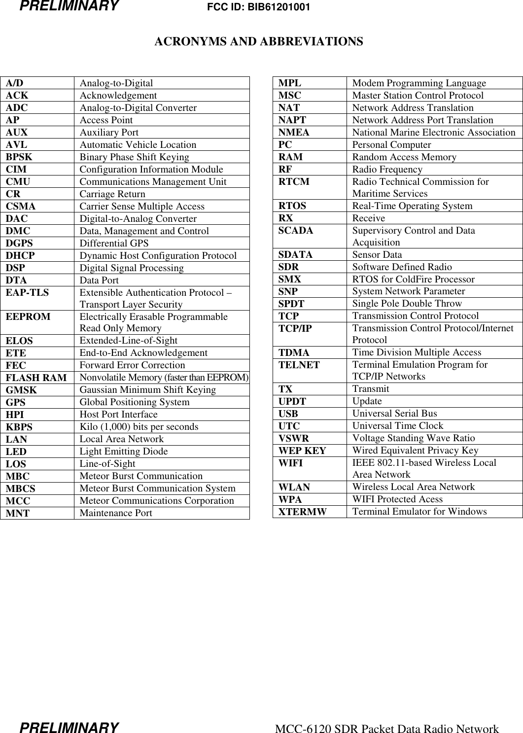

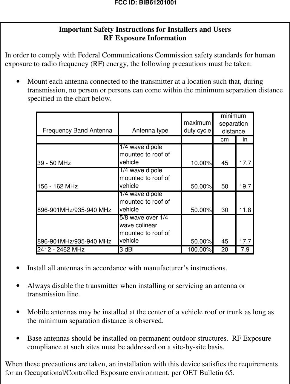
![PRELIMINARY FCC ID: BIB61201001 INTALLATION 3-6 PRELIMINARY MCC-6120 SDR Packet Data Radio Network 3.2.2.1 DC Power Input The MCC-6120 SDR requires a power source that can deliver up to 25 amps of pulsed power (100 msec) out of a +12 VDC to +14VDC power source. The 25 amp power demand will cause a voltage drop to occur at the transmitter input, resulting in reduced transmit power, unless the power cable to the source is sized appropriately. MCC recommends using two #16 AWG wires for both the power and ground and a cable length that does not exceed 10 feet. If a longer cable is required use #14 AWG. MCC provides a standard 6 foot power cable with lugs for connecting to a 3/8” battery post (Part No. 14001350-01). The power connector pins are as follows: The voltage at pins 1 and 4 should not drop by more than 2VDC during transmission. I/O Port DC Power Input GPS Antenna Port Ethernet & USB Ports 900 MHz (UHF) Antenna Port [MCC-6100 only] 802.11(b) Antenna Port Low Band Antenna Port High Band Antenna Port](https://usermanual.wiki/Meteorcomm/61201001.Users-Manual-Prelim/User-Guide-736103-Page-27.png)
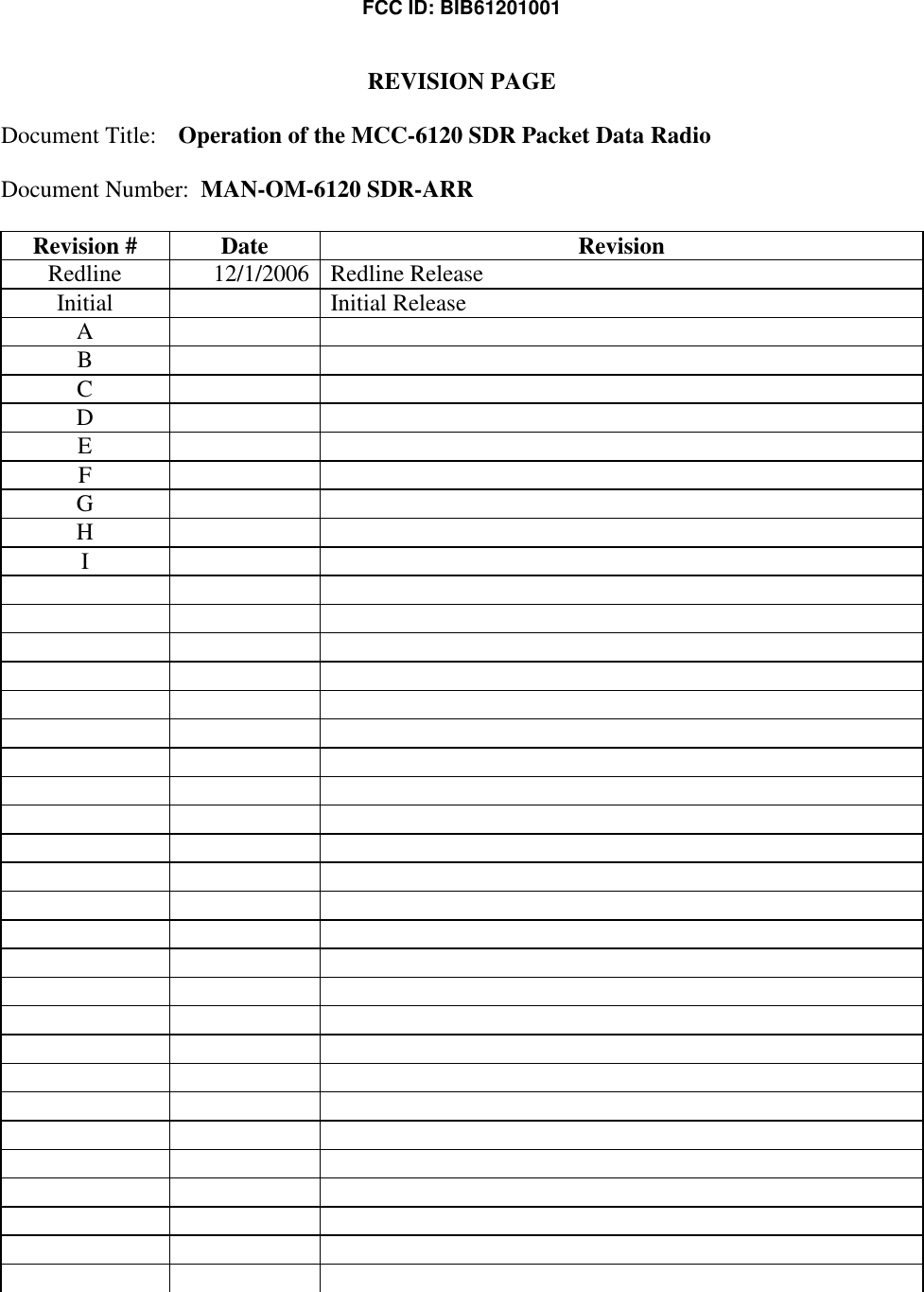
![PRELIMINARY FCC ID: BIB61201001 INTALLATION 3-14 PRELIMINARY MCC-6120 SDR Packet Data Radio Network At this time all configuration data is loaded from Program Memory into RAM. This data will remain in RAM until power cycled. This is the type of message that should be displayed when you first apply power to the unit during a field installation, and for each subsequent power cycle of the radio. After power is applied to the radio all parameters that were entered and saved during the previous session will be reloaded from Flash2 memory. If you want to load factory defaults, power cycle the unit while holding the lower case f key down. After about 10-15 f’s are displayed, release the key and you should see the following message: +fffffffffffffffffffffffffff Ver 1.0 SDR Boot... (Entry due to operator request) 1.. Factory Default 9.. Launch Application Enter a 1 followed by carriage return to restart with factory default parameters. Enter a 9 to restart the application without changing the stored parameters. If you restart with factory defaults, the proper script file must be re-entered into the MCC-6120 SDR using XTERMW. (Refer to Section 3.3.3.5 for more information on using script files.) If you do not have a script file to load you can go through the following procedure to manually start the unit. 3.3.3 Initialization Procedures The following initialization procedures should now be performed in the order they are given below. 3.3.3.1 Verify Device Type The MCC-6120 SDR must be programmed to operate as a particular device type, such as Remote Station, Repeater, or Base, depending on your network configuration. The device type is normally set at the factory prior to shipment to ensure proper integration with your network. Use the following command to display what device type the unit is configured as: DEVICE [ENTER]](https://usermanual.wiki/Meteorcomm/61201001.Users-Manual-Prelim/User-Guide-736103-Page-35.png)
![PRELIMINARY FCC ID: BIB61201001 INTALLATION 3-15 PRELIMINARY MCC-6120 SDR Packet Data Radio Network Always check with your System Administrator to determine which device type your unit should be configured as. For example, if the device should be a Remote Station and it is not currently configured properly, you can change the device type, as follows: DEVICE,REMOTE [ENTER] SAVE [ENTER] CAUTION Do not change the device type unless told to do so by your System Administrator. Changing the device type can make your unit cease operating and can impact communications throughout the entire network. 3.3.3.2 Verify ID Number Every MCC unit is programmed at the factory with a 16-bit unit ID. To display the unit ID number on the operator terminal, enter: ID [ENTER] Contact your System Administrator to make sure this ID is registered in the network configuration database. Under some circumstances the ID may have to be changed on-site. This can only be done if the ID is not locked. CAUTION ID changes must be coordinated with both MCC and your System Administrator. Failure to do so may result in data or messages being misrouted or lost. If the site is equipped with a CIM (Configuration Information Module), the ID for the MCC-6120 will be set from the CIM. 3.3.3.3 Verify Channel Frequency The MCC-6120 SDR is programmed at the factory with the authorized frequencies to be used on a specific channel in your network. These channels and frequencies are stored in Parameter memory and cannot be changed. Verify that the correct channel and frequency is configured by entering the command: CHANNEL [ENTER] or CHAN [ENTER] for short cut](https://usermanual.wiki/Meteorcomm/61201001.Users-Manual-Prelim/User-Guide-736103-Page-36.png)
![PRELIMINARY FCC ID: BIB61201001 INTALLATION 3-16 PRELIMINARY MCC-6120 SDR Packet Data Radio Network This shows you the active or “primary” channel number and TX and RX frequency pair, plus up to 20 additional frequency pairs for channels that may be programmed at the factory. For example, the following table could be displayed: +chan 11/14/05 15:11:26 Primary Channel TX mhz RX mhz Mod-Val 01 44.5800 44.5800 1 11/14/05 15:11:26 Channel Table: Channel TX mhz RX mhz Mod-Val >01* 44.5800 44.5800 1 CAUTION Do not change the frequency pair unless told to do so by your System Administrator. Changing the frequency pair can make your unit stop communicating with the network. 3.3.3.4 Select Site Name A descriptive name may be given to the site where the MCC-6120 SDR is being installed. The selected site name must be coordinated with your System Administrator. To enter a site name use the following command: SITE NAME, nnnnnn [ENTER] where: nnnnnn = maximum of 32 alpha-characters CAUTION Please double-check the site name entry for correct spelling and spacing. Data from a site with an incorrect site name will be mishandled or misrouted by the Host. An incorrect site name can result in significant effort to recover misrouted data. 3.3.3.5 Enter Script Files The appropriate Script File is usually programmed into the MCC-6120 SDR at the factory prior to shipment. If the appropriate Script File has already not been entered, a new file can be loaded from your operator terminal using XTERMW software. There is one Script File that uniquely programs the MCC-6120 SDR to operate as a Remote Station in your specific or MeteorComm network. NOTE If the site is equipped with a CIM (Configuration Information Module), the MCC-6120 will automatically be scripted from the CIM.](https://usermanual.wiki/Meteorcomm/61201001.Users-Manual-Prelim/User-Guide-736103-Page-37.png)
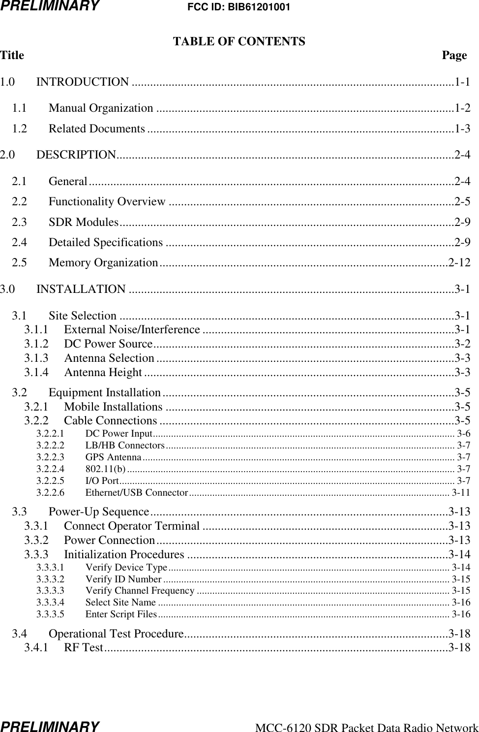
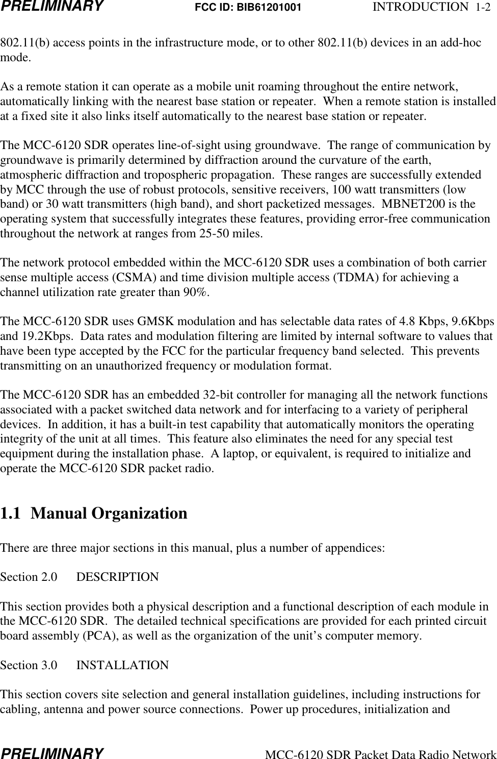
![PRELIMINARY FCC ID: BIB61201001 INTALLATION 3-18 PRELIMINARY MCC-6120 SDR Packet Data Radio Network 3.4 Operational Test Procedure 3.4.1 RF Test A very thorough RF test can be made by entering the command TEST [ENTER]. TEST causes the processor to turn the transmitter ON and measures the forward and reverse RF power that is being transmitted. It also measures the battery voltage under load and the antenna noise voltage. The following response will be displayed on the operator terminal: syncs xmits acks pwr-fwd pwr-rev v-bat det-rf resets xxxx yyyy zzzz aaaa bbbb ccc ddd eee where: xxxx = # of sync patterns received from the master station. yyyy = # of transmissions made by the MCC-6120 SDR. zzzz = # of acknowledgements received from the Master Station. aaaa = Forward power in watts. This should be greater than 80 watts. bbbb = Reflected power in watts. This should be less than 5 watts. ccc = Battery voltage under load (while transmitting). This should be greater than 10.6 VDC. ddd = Received signal strength in dBm. This will normally be the noise level at the antenna and should read about –120. eee = Number of times the radio has rebooted. NOTE The forward RF power should be at least 80 watts when operating at Low Band VHF, and 25 watts when operating in High Band VHF if the battery voltage is normal. If it is lower than these values check for proper cabling to the power source (see Section 3.2.2.1.). If the reverse RF power is greater than 5 watts on any channel check the antenna and coaxial cabling for proper installation. If both the forward and reverse power are low, the transmitter may be automatically shutting down due to an antenna VSWR greater than 3:1. Check the antenna and coaxial cabling for proper installation. The DET RF value indicates the level of the RF signal plus noise at the antenna in dBM (dB above or below 1 milliwatt of power). Use the mm,50,dist command to obtain just the noise value. This noise level should be less than -90 dBM. The lower the number the lower the noise and the larger the operating range of the unit will be. Refer to Section 3.1 for reducing site noise conditions. An overall figure of merit for the link performance is the XMIT to ACK ratio. If this ratio is 3:1 or lower, the overall performance will be very good. This completes the initialization and power-up sequence of the MCC-6120 SDR. The unit is now ready for operation.](https://usermanual.wiki/Meteorcomm/61201001.Users-Manual-Prelim/User-Guide-736103-Page-39.png)