Meteorcomm 61201001 Land Mobile Packet Data Transceiver User Manual MCC 6120 SDR Manual new High Band no 900
Meteorcomm LLC Land Mobile Packet Data Transceiver MCC 6120 SDR Manual new High Band no 900
Contents
- 1. Users Manual Prelim
- 2. Amended Operating Manual
- 3. RF Exposure Guide
Users Manual Prelim

FCC ID: BIB61201001
OPERATION
OF THE
MCC-6120 SDR
PACKET DATA RADIO
MAN-OPS-6120 SDR-ARR
PRELIMINARY
December 1, 2006
Meteor Communications Corporation
22614 66
th
Avenue South.
Kent, WA 98032
Tel: (253) 872-2521
Fax: (253) 872-7662
E-mail: mcc@meteorcomm.com
On the Web: www.meteorcomm.com
2006 by Meteor Communications Corporation
all rights reserved

FCC ID: BIB61201001
GENERAL WARRANTY
Meteor Communications Corporation (MCC) warrants that its products conform to the
published specifications and are free from manufacturing and material defects for one year after
shipment. Warranty-covered equipment that fails during the warranty period will be promptly
repaired at MCC’s facility in Kent, Washington.
International customers are required to pay shipping costs to the MCC facility, with Seattle as the
point of U.S. entry. MCC will pay incoming U.S. duty fees. MCC will pay for shipping costs
to return the equipment to the customer, with the customer paying any and all return duty fees.
This warranty is contingent upon proper use of the equipment and does not cover equipment that
has been modified in any way without MCC’s approval or has been subjected to unusual
physical or electrical stress, or on which the original identification marks have been removed or
altered.

FCC ID: BIB61201001
Important Safety Instructions for Installers and Users
RF Exposure Information
In order to comply with Federal Communications Commission safety standards for human
exposure to radio frequency (RF) energy, the following precautions must be taken:
• Mount each antenna connected to the transmitter at a location such that, during
transmission, no person or persons can come within the minimum separation distance
specified in the chart below.
Frequency Band Antenna Antenna type
maximum
duty cycle
cm
in
39 - 50 MHz
1/4 wave dipole
mounted to roof of
vehicle 10.00% 45 17.7
156 - 162 MHz
1/4 wave dipole
mounted to roof of
vehicle 50.00% 50 19.7
896-901MHz/935-940 MHz
1/4 wave dipole
mounted to roof of
vehicle 50.00% 30 11.8
896-901MHz/935-940 MHz
5/8 wave over 1/4
wave colinear
mounted to roof of
vehicle 50.00% 45 17.7
2412 - 2462 MHz
3 dBi
100.00%
20
7.9
minimum
separation
distance
• Install all antennas in accordance with manufacturer’s instructions.
• Always disable the transmitter when installing or servicing an antenna or
transmission line.
• Mobile antennas may be installed at the center of a vehicle roof or trunk as long as
the minimum separation distance is observed.
• Base antennas should be installed on permanent outdoor structures. RF Exposure
compliance at such sites must be addressed on a site-by-site basis.
When these precautions are taken, an installation with this device satisfies the requirements
for an Occupational/Controlled Exposure environment, per OET Bulletin 65.

FCC ID: BIB61201001
REVISION PAGE
Document Title: Operation of the MCC-6120 SDR Packet Data Radio
Document Number: MAN-OM-6120 SDR-ARR
Revision # Date Revision
Redline 12/1/2006
Redline Release
Initial
Initial Release
A
B
C
D
E
F
G
H
I
PRELIMINARY
FCC ID: BIB61201001
PRELIMINARY
MCC-6120 SDR Packet Data Radio Network
TABLE OF CONTENTS
Title Page
1.0 INTRODUCTION .........................................................................................................1-1
1.1 Manual Organization .................................................................................................1-2
1.2 Related Documents....................................................................................................1-3
2.0 DESCRIPTION..............................................................................................................2-4
2.1 General.......................................................................................................................2-4
2.2 Functionality Overview .............................................................................................2-5
2.3 SDR Modules.............................................................................................................2-9
2.4 Detailed Specifications ..............................................................................................2-9
2.5 Memory Organization..............................................................................................2-12
3.0 INSTALLATION ..........................................................................................................3-1
3.1 Site Selection .............................................................................................................3-1
3.1.1 External Noise/Interference ..................................................................................3-1
3.1.2 DC Power Source..................................................................................................3-2
3.1.3 Antenna Selection.................................................................................................3-3
3.1.4 Antenna Height.....................................................................................................3-3
3.2 Equipment Installation...............................................................................................3-5
3.2.1 Mobile Installations ..............................................................................................3-5
3.2.2 Cable Connections ................................................................................................3-5
3.2.2.1
DC Power Input..................................................................................................................... 3-6
3.2.2.2
LB/HB Connectors................................................................................................................ 3-7
3.2.2.3
GPS Antenna......................................................................................................................... 3-7
3.2.2.4
802.11(b)............................................................................................................................... 3-7
3.2.2.5
I/O Port.................................................................................................................................. 3-7
3.2.2.6
Ethernet/USB Connector..................................................................................................... 3-11
3.3 Power-Up Sequence.................................................................................................3-13
3.3.1 Connect Operator Terminal ................................................................................3-13
3.3.2 Power Connection...............................................................................................3-13
3.3.3 Initialization Procedures .....................................................................................3-14
3.3.3.1
Verify Device Type............................................................................................................. 3-14
3.3.3.2
Verify ID Number ............................................................................................................... 3-15
3.3.3.3
Verify Channel Frequency .................................................................................................. 3-15
3.3.3.4
Select Site Name ................................................................................................................. 3-16
3.3.3.5
Enter Script Files................................................................................................................. 3-16
3.4 Operational Test Procedure......................................................................................3-18
3.4.1 RF Test................................................................................................................3-18
PRELIMINARY
FCC ID: BIB61201001
PRELIMINARY
MCC-6120 SDR Packet Data Radio Network
LIST OF FIGURES
Figure Page
1.0 Typical Network ....................................................................................................... 1-1
2.1-1 MCC-6120 SDR Photograph..................................................................................... 2-1
2.2-1 MCC-6120 SDR Radio.............................................................................................. 2-2
LIST OF TABLES
Table Page
2.1 MCC-6120 SDR General Specifications ................................................................... 2-9
2.2 MCC-6120 SDR Low Band Receiver Specifications................................................ 2-10
2.3 MCC-6120 SDR Low Band Transmitter Specifications ........................................... 2-10
2.4 MCC-6120 SDR High Band Receiver Specifications ............................................... 2-11
2.5 MCC-6120 SDR High Band Transmitter Specifications........................................... 2-11
2.6 MCC-6120 SDR Microprocessor Specifications....................................................... 2-12

PRELIMINARY
FCC ID: BIB61201001
PRELIMINARY
MCC-6120 SDR Packet Data Radio Network
CONVENTIONS
The following conventions are used in this manual:
When presented in the text, user commands and computer printout are boldfaced; e.g., Enter
DELETE. Command parameters are presented in lower case; e.g., DEFINE,id. Optional
parameters are enclosed in brackets; e.g., TIME{,hh:mm:ss}
Names of terminal keys are capitalized and enclosed in square brackets when mentioned in the
text; e.g., Press [ESC].
Names of hardware switches, meters, etc. are capitalized; e.g., PWR ON switch.
NOTE
Used for special emphasis of material
IMPORTANT
Used for added emphasis of material
CAUTION
Cautions the operator to proceed carefully
WARNING! WARNING! WARNING!
Used in cases where failure to heed the message may result
in personal injury or equipment damage.

PRELIMINARY
FCC ID: BIB61201001
PRELIMINARY
MCC-6120 SDR Packet Data Radio Network
ACRONYMS AND ABBREVIATIONS
A/D Analog-to-Digital
ACK Acknowledgement
ADC Analog-to-Digital Converter
AP Access Point
AUX Auxiliary Port
AVL Automatic Vehicle Location
BPSK Binary Phase Shift Keying
CIM Configuration Information Module
CMU Communications Management Unit
CR Carriage Return
CSMA Carrier Sense Multiple Access
DAC Digital-to-Analog Converter
DMC Data, Management and Control
DGPS Differential GPS
DHCP Dynamic Host Configuration Protocol
DSP Digital Signal Processing
DTA Data Port
EAP-TLS Extensible Authentication Protocol –
Transport Layer Security
EEPROM Electrically Erasable Programmable
Read Only Memory
ELOS Extended-Line-of-Sight
ETE End-to-End Acknowledgement
FEC Forward Error Correction
FLASH RAM Nonvolatile Memory (faster than EEPROM)
GMSK Gaussian Minimum Shift Keying
GPS Global Positioning System
HPI Host Port Interface
KBPS Kilo (1,000) bits per seconds
LAN Local Area Network
LED Light Emitting Diode
LOS Line-of-Sight
MBC Meteor Burst Communication
MBCS Meteor Burst Communication System
MCC Meteor Communications Corporation
MNT Maintenance Port
MPL Modem Programming Language
MSC Master Station Control Protocol
NAT Network Address Translation
NAPT Network Address Port Translation
NMEA National Marine Electronic Association
PC Personal Computer
RAM Random Access Memory
RF Radio Frequency
RTCM Radio Technical Commission for
Maritime Services
RTOS Real-Time Operating System
RX Receive
SCADA Supervisory Control and Data
Acquisition
SDATA Sensor Data
SDR Software Defined Radio
SMX RTOS for ColdFire Processor
SNP System Network Parameter
SPDT Single Pole Double Throw
TCP Transmission Control Protocol
TCP/IP Transmission Control Protocol/Internet
Protocol
TDMA Time Division Multiple Access
TELNET Terminal Emulation Program for
TCP/IP Networks
TX Transmit
UPDT Update
USB Universal Serial Bus
UTC Universal Time Clock
VSWR Voltage Standing Wave Ratio
WEP KEY Wired Equivalent Privacy Key
WIFI IEEE 802.11-based Wireless Local
Area Network
WLAN Wireless Local Area Network
WPA WIFI Protected Acess
XTERMW Terminal Emulator for Windows
PRELIMINARY
FCC ID: BIB61201001
INTRODUCTION 1-1
PRELIMINARY
MCC-6120 SDR Packet Data Radio Network
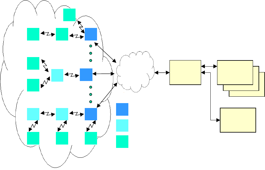
1.0 INTRODUCTION
The MCC-6120 SDR PACKET DATA RADIO is used in MCC’s Network. This is an
Extended Line-of-Sight (ELOS), packet switched, digital data network that operates on a single
frequency in the low VHF band (40-50 MHz), a high VHF band (151-162 MHz), or a UHF band
(896-901/935-940 MHz). A network has a cellular structure that uses the programmable MCC-
6120 SDR as a base station, a repeater and as a remote station. One or more Data Centers are
normally used for the central collection and distribution of data to a customer’s office. The
network can be as small as one base station or may be comprised of thousands of base stations,
repeaters and remote stations. The networks are used for position reporting in mobile
applications (AVL), fixed site data collection (SCADA) and messaging.
TYPICAL NETWORK
FIGURE 1.0
The MCC-6120 SDR can be dynamically programmed to operate in three distinct modes: (1) as
a base station, (2) a repeater station, or (3) as a remote station. As a base station it is connected
to a Data Center or Host through a Data Network. The Data Network can be frame relay,
microwave, the Internet or other forms of existing infrastructure. The MCC-6120 SDR has two
Ethernet (10MHz) network interface adaptors. If a direct connection is not available the MCC-
6120 SDR operates as a repeater into the nearest base station. Multiple repeater links may be
chained together for expansion of the network when no other communication infrastructure is
available. In addition the unit has an 802.11(b) network adaptor that can be used to connect to
CLIENT’S
OFFICES
DATA
NETWORK
DATA CENTER
OR
HOST
CLIENT’S
OFFICES
B
R
M
BASE STATION
REMOTE STATION (FIXED OR MOBILE)
REPEATER STATION
M B
M
M
M
M
RB
R
MMM
R B
ELOS RF NETWORK
OTHER
CLIENTS
PRELIMINARY
FCC ID: BIB61201001
INTRODUCTION 1-2
PRELIMINARY
MCC-6120 SDR Packet Data Radio Network
802.11(b) access points in the infrastructure mode, or to other 802.11(b) devices in an add-hoc
mode.
As a remote station it can operate as a mobile unit roaming throughout the entire network,
automatically linking with the nearest base station or repeater. When a remote station is installed
at a fixed site it also links itself automatically to the nearest base station or repeater.
The MCC-6120 SDR operates line-of-sight using groundwave. The range of communication by
groundwave is primarily determined by diffraction around the curvature of the earth,
atmospheric diffraction and tropospheric propagation. These ranges are successfully extended
by MCC through the use of robust protocols, sensitive receivers, 100 watt transmitters (low
band) or 30 watt transmitters (high band), and short packetized messages. MBNET200 is the
operating system that successfully integrates these features, providing error-free communication
throughout the network at ranges from 25-50 miles.
The network protocol embedded within the MCC-6120 SDR uses a combination of both carrier
sense multiple access (CSMA) and time division multiple access (TDMA) for achieving a
channel utilization rate greater than 90%.
The MCC-6120 SDR uses GMSK modulation and has selectable data rates of 4.8 Kbps, 9.6Kbps
and 19.2Kbps. Data rates and modulation filtering are limited by internal software to values that
have been type accepted by the FCC for the particular frequency band selected. This prevents
transmitting on an unauthorized frequency or modulation format.
The MCC-6120 SDR has an embedded 32-bit controller for managing all the network functions
associated with a packet switched data network and for interfacing to a variety of peripheral
devices. In addition, it has a built-in test capability that automatically monitors the operating
integrity of the unit at all times. This feature also eliminates the need for any special test
equipment during the installation phase. A laptop, or equivalent, is required to initialize and
operate the MCC-6120 SDR packet radio.
1.1 Manual Organization
There are three major sections in this manual, plus a number of appendices:
Section 2.0 DESCRIPTION
This section provides both a physical description and a functional description of each module in
the MCC-6120 SDR. The detailed technical specifications are provided for each printed circuit
board assembly (PCA), as well as the organization of the unit’s computer memory.
Section 3.0 INSTALLATION
This section covers site selection and general installation guidelines, including instructions for
cabling, antenna and power source connections. Power up procedures, initialization and

PRELIMINARY
FCC ID: BIB61201001
INTRODUCTION 1-3
PRELIMINARY
MCC-6120 SDR Packet Data Radio Network
functional test procedures are described that should be performed prior to placing the MCC-6120
SDR on-line within the network.
1.2 Related Documents
Additional documents and application notes that may be helpful in the operation of the MCC-
6120 SDR Packet Radio in an ELOS Network are given below. They can be obtained from
MCC or downloaded from MCC’s web site, www.meteorcomm.com.
1.2.1 MBNET 200
A Complete List of all Commands and Printouts
1.2.2 DMC
Data Monitor and Control, DMC 6.338, Users Manual, December 22, 2005
1.2.3 XTERMW
Operation of the XTERMW Terminal Emulation Program for Windows, April 2, 2001
1.2.4 FleetTrak
Network Performance and System Capacity, EDT 11037, March 9, 1999
1.2.5 MPL
Modem Programming Language Users Manual, September 26, 2004
1.2.6 Related Application Notes:
• MCC-545 Event Programming, March 5, 2003
• CIM management with Password Protect Mode, April 1, 2003
• MSC2 Protocol Interface Control Document, January 31, 2005
• CR10X Data Acquisition, January 25, 2000
PRELIMINARY
FCC ID: BIB61201001
DESCRIPTION 2-4
PRELIMINARY
MCC-6120 SDR Packet Data Radio Network
2.0 DESCRIPTION
2.1 General
The MCC-6120 SDR Packet Data Radio provides packet switched communications from fixed
or mobile sites to a central Host. It can be used for sending and receiving messages, position
reporting, data logging, or other custom applications.
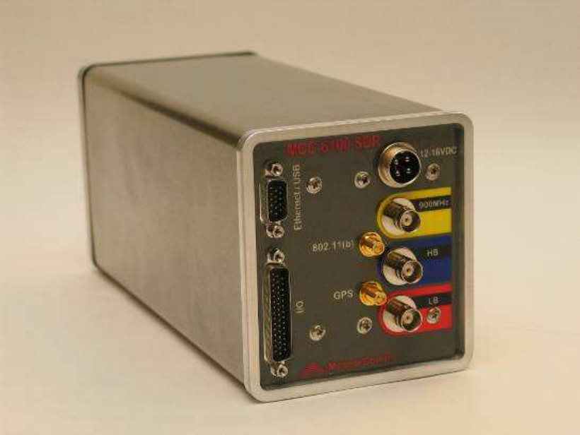
The unit is packaged in a stainless steel, weather-resistant enclosure that measures 9.5”L X
4.0”W X 4.3” H and weighs 6.0 pounds.
A photograph of the MCC-6120 SDR is given in Figure 2.1-1.
MCC-6120 SDR PHOTOGRAPH
FIGURE 2.1-1
PRELIMINARY
FCC ID: BIB61201001
DESCRIPTION 2-5
PRELIMINARY
MCC-6120 SDR Packet Data Radio Network
2.2 Functionality Overview
Introduction
The MCC-6120 SDR is the next step in the evolution of the MCC family of Packet Data Radios.
The necessity for providing customers with simple, yet powerful, fixed and mobile
communications capabilities has led to the development of a Software Defined Radio (SDR)
coupled to a Communications Management Unit (CMU). The previous design, known as the
MCC-545C, used a 20 MHz Motorola 68332 processor, 40 MHz Low-Band VHF GMSK analog
receiver/DSP transmitter, and had three RS-232 serial ports for interfacing to external equipment.
The MCC-6120 SDR has added additional capabilities including a 50 MHz Motorola ColdFire
5485 processor, TI Digital Signal Processor, TCP/IP stack, two Ethernet ports, an 802.11b port,
two USB ports, and a second RF transceiver in the 160 MHz band.
This section will describe the type of message transport services that are provided, then describe
the commands required to configure the various services.
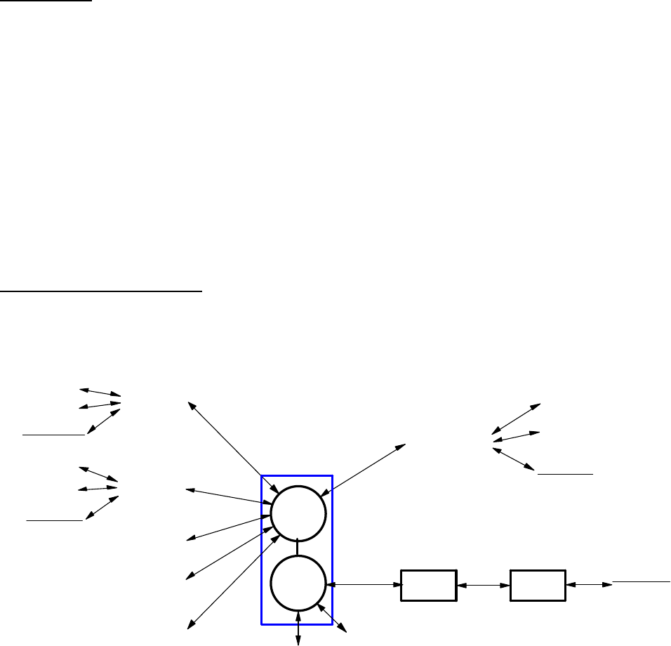
Message Transport Services
Figure 2.2-1 shows the CMU in relation to its ports and Low-Band Radio Link. This paragraph
will discuss the ways the CMU can provide message transport services between the external
applications that may be attached to the various ports.
TCP/IP Ethernet-1 TELNET
TELNET
TCP/IP
TCP/IP 802.3
TCP/IP TCP/IP
802.3
Ethernet-2
TELNET
CMU
RS-232TCP/IP
USB
USB
TELNET
RS-232
MBNET 802.3
SDR 3
Base DTCP/IP
Low Band
SMX FILE High Band
ATCS
SDRNET.DWG
MeteorComm
SDR Radio
802.11b
WiFi 802-11b
MSC
MSC
MSC
MSC MSC
MSC
FIGURE 2.2-1
The MCC software architecture allows any of its ports to be assigned to a wide variety of device
drivers. This provides a very flexible means of configuring any radio to meet particular

PRELIMINARY
FCC ID: BIB61201001
DESCRIPTION 2-6
PRELIMINARY
MCC-6120 SDR Packet Data Radio Network
Customer and system requirements. New device drivers have been developed to provide this
same flexibility to the Ethernet and WIFI ports. For example, a laptop, tablet or palm computer
can be set up to run Xtermw.exe connected through one of the Ethernet ports or WIFI (in ad-hoc
mode) to operate as the maintenance terminal. Another example is that a local host computer
can connect through one of the Ethernet ports and route IP packets through the CMU and WIFI
port (in Infrastructure mode) to an Access Point, and on to a WAN-based Central Host System.
TCP/IP
The TCP/IP stack is a shared library that allows the Ethernet and WIFI ports to operate as
traditional IP Network connections with IP-Forwarding (routing). In the MCC-545C, use of
Ethernet connections was provided only by external terminal-server boxes connected to the RS-
232 serial ports. Only ASCII (TELNET) and MSC or MSC2 protocols could be used for
interfacing with external equipment. The MCC-6120 SDR CMU has the Ethernet and WIFI
built-in, and can be directly interfaced to many Ethernet Devices using the standard “Sockets”
software API.
Each Ethernet and WIFI port can be given its own IP address. The initial version of MCC-6120
SDR software allows each port to have from 1 to 4 application “ports”. These are numbered
from 4000 – 4011.
DHCP Client
Either Ethernet port or the WIFI port can have DHCP-Client enabled to automatically get an IP
address from a DHCP server located on its subnet.
DHCP Server
Either Ethernet port or the WIFI port can have DHCP-Server enabled to automatically supply an
IP address to devices located on its subnet. This is a limited implementation and can only supply
IP addresses, not any other configuration data options.
NAT
The Network Address Translation (NAT) protocol can be configured to separate a private subnet
from the public network. As the private hosts send IP packets to the public network, the NAT
routing function translates the private IP addresses into public IP addresses. As packets come
back from the public network, the translation is reversed and the packet delivered to the correct
private IP address. Options exist for assigning static IP addresses, and defining dynamic IP
addresses to be used for the translation.
NAPT
The Network Address Port Translation (NAPT) protocol is similar to NAT, except a range of
port numbers are defined to be used by the router in the address translation. In this way, a single
private and public IP address can be used on each side of the router. The private processes are

PRELIMINARY
FCC ID: BIB61201001
DESCRIPTION 2-7
PRELIMINARY
MCC-6120 SDR Packet Data Radio Network
assigned one of the port numbers out of the given port number set when they send IP packets to
the public Network. Address translation happens using the public IP address and newly assigned
port number.
ASCII (TELNET)
The ASCII protocol is basically a dumb serial protocol transported over a TCP connection. This
is useful for connections to maintenance terminals that use XTERMW.EXE as a terminal
emulator.
MSC Protocol Suite
The Master Station Control (MSC) protocol suite is a set of packet protocols that can be used on
any RS-232 port as well as transported over any TCP connection. The suite is composed of three
packet protocols that operate much like UDP, in that data is transported from source to
destination without establishing an end-to-end TCP/IP connection first. The source and
destination addressing uses 16-bit Radio ID’s instead of IP addresses.
MSC is the original packet protocol and operates with a stop-and-wait link layer where each
packet is sent by first asking permission, then sending the packet if permitted.
MSC2 is an extension of MSC. It uses the same packet-body message and command layer
formats, but uses a windowing type of link layer to achieve higher throughput.
MSC3 is an extension of the command layer formats to allow MSC or MSC2 link layer
connections to operate on multiple ports.
WIFI, AP, AD-HOC, Wireless Security
The WIFI port (802.11b) can be set up to connect to an Access Point (AP) in Infrastructure
mode, or to other WIFI devices in ad-hoc mode. The WIFI port can not operate in both modes at
once. An option can set the port to AUTO mode where it will use an AP if one is in range, or
else it can use an ad-hoc connection. The choice of SSID strings is user-configurable.
Once connected, the WIFI link operates like the Ethernet links with full TCP/IP capability. The
host processors connected to an Ethernet port will be able to connect through the CMU and WIFI
line to IP addresses on the WAN that the AP is connected to. Roaming between access points is
not yet supported.
Two security options, WEP and WPA, are available (in addition to no security):
WEP Wired Equivalency Privacy – This mode uses a password to act as an encryption
key. If a 5-byte key is used, then 64-bit encryption is utilized. If a 13-byte key is
used then 128-bit encryption is utilized. The WEP key is entered in hexadecimal
format using only 0-9 and A-F characters. Authentication must be handled at the
application level.

PRELIMINARY
FCC ID: BIB61201001
DESCRIPTION 2-8
PRELIMINARY
MCC-6120 SDR Packet Data Radio Network
WPA WIFI Protected Access – This mode also uses encryption as well as
authentication. There are three WPA variations supported:
PSK Pre Shared Key – A passphrase of 8-63 ASCII characters is
required. The passphrase is used to generate an encryption key.
This is sometimes called “WPA-Personal” (and should not be
confused with different PSK modulation schemes used by the
various SDR transceivers).
EAP-TLS Extensible Authentication Protocol–Transport Layer Security
– This mode uses certificates for authentication. A password (up
to 32 bytes expressed in hexadecimal format) is needed to decrypt
key information from the certificate. Access points are connected
to a Radius server which performs authentication.
EAP-TTLS Extensible Authentication Protocol–Tunneled Transport
Layer Security – This mode uses certificates only on the server
side for authentication. A password (up to 64 ASCII characters) is
needed to obtain key information. Access points are connected to
a Radius server which performs authentication.
USB Ports and SMX File
Two USB ports are provided. One port is for connecting a Flash-memory device for use as disk
file storage. The SMX-file software device-driver lets application software in the CMU create,
delete, read and write Flash-memory files.
The second USB port is for connecting serial devices that emulate RS-232 ports. This option is
not yet available.

PRELIMINARY
FCC ID: BIB61201001
DESCRIPTION 2-9
PRELIMINARY
MCC-6120 SDR Packet Data Radio Network
2.3 SDR Modules
The MCC-6120 SDR contains four printed circuit board assemblies as shown in Figure 2.3-1.
• A 32-bit Communications Management Unit (CMU) microprocessor controller performs
the radio control, link and network protocol functions. This assembly also contains a
digital signal processor (DSP) and a digital-to-analog converter (DAC) for generating the
GMSK RF signal. The DSP also receives and demodulates the receive GMSK signals on
all bands.
• A 30W, 3-stage power amplifier, filters, and mixers for operation in the 151-162 MHz
band
• A 100W, 3-stage power amplifier in the 39-50 MHz band.
• A 12-channel GPS receiver that can be mounted on the processor board as an optional
subassembly.
• An 802.11(b) Module (15mW) mounted on the CMU board.
All components are soldered in place using surface mount technology. As an option, the boards
can be conformal coated with an acrylic encapsulate that contains a tropicalizing, anti-fungal
agent to provide additional protection against moisture and contamination.
2.4 Detailed Specifications
The detailed specifications for each of the printed circuit board assemblies are given in Tables
2.1 through 2.6.
MCC-6120 SDR GENERAL SPECIFICATIONS
CHARACTERISTIC SPECIFICATION
Dimensions 10.6”L X 4.0”W X 4.4”H
Weight 6.0 lbs.
Temperature Range -30° to 60° C (-22° to 140° F)
Power Requirements 12 V
DC
Nominal (10-15 V
DC
)
Standby: 600 mA (Continuous)
Transmit: 22 Amps Nominal (Low Band)
8 Amps Nominal (High Band)
TABLE 2.1

PRELIMINARY
FCC ID: BIB61201001
DESCRIPTION 2-10
PRELIMINARY
MCC-6120 SDR Packet Data Radio Network
MCC-6120 SDR LOWBAND RECEIVER SPECIFICATIONS
CHARACTERISTIC SPECIFICATION
Frequency 39-50 MHz .0005%
DDS 1 Hz steps
Modulation: Rate
Type
Format
4.8kbps, 9.6 kbps, and 19.2 kbps
BPSK (4.8 kbps); GMSK (9.6kbps & 19.2kbps)
NRZ
Noise Figure < 8 dB minimum
Sensitivity: Bit Error Rate < 10
-3
at 9.6
kbps -113 dBm at 9.6 kbps -110 at 19.2 kbps
IF Bandwidth (3/80 db) 13/40 kHz typical
RF Bandwidth (3 db) 13 MHz typical
Signal Acquisition Time < 5 msec
3
rd
Order Intercept Point >- 4 dBm
Image Response Attenuation > 70 dB minimum
Spurious Response Attenuation > 70 dB minimum
I/O MCC Standard (Refer to Section 3.2)
TABLE 2.2
MCC-6120 SDR LOWBAND TRANSMITTER SPECIFICATIONS
CHARACTERISTIC SPECIFICATION
Frequency 39-50 MHz .0005% Synthesized 10kHz
steps
RF Power Output > 100 Watts at 12 V
DC
Input
Load VSWR < 2:1 Rated Power
Harmonic Levels 70 dB below Unmodulated Carrier
Modulation: Rate
Type
Format
4.8kbps, 9.6 kbps, and 19.2 kbps
BPSK (4.8 kbps); GMSK (9.6kbps & 19.2kbps)
NRZ
Spurious > 70 dB below Unmodulated Carrier
Transmit Modulation Spectrum 10 kHz offset – 40 db
25 kHz offset – 70 db
Tx Duty Cycle 16% Max without shutting down transmitter
20% will shut down the transmitter
T/R Switch Solid-State
Switching Time < 100 microseconds
I/O MCC Standard (Refer to Section 3.2)
High VSWR Protection Withstands Infinite VSWR
TABLE 2.3

PRELIMINARY
FCC ID: BIB61201001
DESCRIPTION 2-11
PRELIMINARY
MCC-6120 SDR Packet Data Radio Network
MCC-6120 SDR HIGH BAND RECEIVER SPECIFICATIONS
CHARACTERISTIC SPECIFICATION
Frequency 151-160.6 MHz
.0005% DDS 1 Hz steps
Modulation: Rate
Type
Format
4.8kbps, 9.6 kbps, and 19.2 kbps
GFSK (4.8 kbps); GMSK (9.6kbps & 19.2kbps)
NRZ
±5kHz deviation Voice
±2.5kHz deviation Voice
Noise Figure < 9 dB minimum
Sensitivity: Bit Error Rate < 10
-3
at 9.6
kbps -112 dBm
IF Bandwidth (3/80 db) 13/40 kHz typical
RF Bandwidth (3 db) 13 MHz typical
Signal Acquisition Time < 5 msec
3
rd
Order Intercept Point >- 4 dBm
Image Response Attenuation > 70 dB minimum
Spurious Response Attenuation > 70 dB minimum
I/O MCC Standard (Refer to Section 3.2)
TABLE 2.4
MCC-6120 SDR HIGH BAND TRANSMITTER SPECIFICATIONS
CHARACTERISTIC SPECIFICATION
Frequency 151-162 MHz
.0005% Synthesized 10KHz steps
RF Power Output > 30 Watts at 13.5 V
DC
Input
Load VSWR < 2:1 Rated Power
Harmonic Levels 70 dB below Unmodulated Carrier
Modulation: Rate
Type
Format
4.8kbps, 9.6 kbps, and 19.2 kbps
GFSK (4.8 kbps); GMSK (9.6kbps & 19.2kbps)
NRZ
±5kHz deviation Voice
±2.5kHz deviation Voice
Spurious > 70 db below Unmodulated Carrier
Transmit Modulation Spectrum 10 kHz offset – 40 db
25 kHz offset – 70 db
Tx Duty Cycle 16% Max without shutting down transmitter
20% will shut down the transmitter
T/R Switch Solid-State
Switching Time < 100 microseconds
I/O MCC Standard (Refer to Section 3.2)
High VSWR Protection Withstands Infinite VSWR
TABLE 2.5

PRELIMINARY
FCC ID: BIB61201001
DESCRIPTION 2-12
PRELIMINARY
MCC-6120 SDR Packet Data Radio Network
MCC-6120 SDR MICROPROCESSOR SPECIFICATIONS
CHARACTERISTIC SPECIFICATION
Main Processor Motorola MC68332FC 32-bit Embedded
Controller
Memory: Program Storage
Data Storage
Parameter Storage
Calibration Storage
2M x 16 non-volatile Flash memory (Flash1)
64M x 16 dynamic RAM
2M x 16 non-volatile Flash memory (Flash2)
8K EEPROM
Switches: S1 System Reset, Momentary
TABLE 2.6
2.5 Memory Organization
The MCC-6120 SDR has four types of memory:
Program Memory The Program Memory is non-volatile Flash memory (2Meg x 16). This is
also referred to as Flash1 in the documentation. It contains the
MBNET200 image software, the DSP image software, configuration, and
application software. These programs are installed at the MCC facilities at
the time of shipment. The information stored in the Program Memory is
referred to as “factory defaults”.
Parameter Memory The Parameter Memory is non-volatile Flash memory (2Meg x 16). This
is also referred to as Flash2. It contains the configuration data for the unit
such as the customer number, the serial number and ID of the MCC-6120
SDR and the authorized FCC frequencies it may use. This information is
normally programmed into the unit prior to shipment. The Script files are
also stored in Parameter memory, either at the MCC facilities or on site.
Calibration Memory The Calibration Memory is serial Electrically Erasable memory (8,192
Kbyte EEPROM) used to store specific parameters associated with the
calibration of the radio. These parameters are set when the radio is
manufactured and/or when it is recalibrated by trained technicians in a
laboratory. They cannot be changed in the field. These parameters
include:
freqcal Calibrates the 19.2 MHz TCXO
lb_rx-gain Calibrates the Low Band RSSI (detrf)
hb_rx-gain Calibrates the High Band RSSI (detrf)
hb_tx-gain Calibrates the High Band Tx gain
When the unit is rebooted by entering the BOOT command, or whenever
the unit is power cycled, the ColdFire software will reload these
PRELIMINARY
FCC ID: BIB61201001
DESCRIPTION 2-13
PRELIMINARY
MCC-6120 SDR Packet Data Radio Network
parameters into the DSP. They can also be reloaded by entering the
following command LOADCAL.
Data Memory The Data Memory is volatile 64 MByte RAM (16 Meg x 32). Date, time,
executable programs, command parameters and program dynamic data
(messages, data, position, etc) are all stored in RAM during normal
operations.
During normal operation, the MCC-6120 SDR software uses the data and configuration
parameters stored in RAM. If the data information in RAM is lost or corrupted, for whatever
reason, the configuration parameters can be retrieved from Parameter and/or Calibration
memory. This ensures uninterrupted operation.
The RAM contents will be lost under the following conditions:
• The Reboot command is issued.
• The Reset button (S1) is depressed (located inside the unit)
• The internal backup battery fails or is disconnected. (By unsoldering)
• The watchdog timer initiates a restart.
• The unit is powered off
The software will detect these events and will recopy the parameters and configuration values
from Parameter memory back into RAM when operation is resumed.
If the contents of Parameter memory become invalid the unit will revert to the factory defaults in
Program memory.
The Operator Port of the MCC-6120 SDR is programmed with the following default
configuration at the time of shipment:
Baud rate 9600
Data bits 8
Stop bit 1
Parity no
Protocol ASCII
Flow control no
This provides a known starting point when first connecting an operator terminal to the MCC-
6120 SDR. This setting should not be changed.

PRELIMINARY
FCC ID: BIB61201001
INTALLATION 3-1
PRELIMINARY
MCC-6120 SDR Packet Data Radio Network
3.0 INSTALLATION
Site selection and general installation guidelines are provided in this section, including
instructions for cabling, antenna and power source connections. Power up procedures,
initialization and preliminary functional test procedures are described that should be performed
prior to placing the MCC-6120 SDR on-line within the network. The following types of
installations are described:
• Base Stations and Repeaters
• Mobiles
• Fixed Data Collection Sites
3.1 Site Selection
The site selection criteria given in this section is generally applicable for base stations, repeaters
and fixed data sites. General guidelines for mobiles are provided in Section 3.2.1. There are 4
important factors to consider in selecting an optimum site:
• External noise/interference
• DC power source
• Antenna height
• Antenna type
3.1.1 External Noise/Interference
Noise and signal interference can reduce the performance of the MCC-6120 SDR. The most
common sources of noise and interference are as follows:
• Power Line Noise
• Computer-Generated Interference
• External Signal Interference
Power Line Noise
One of the main sources of external noise are high voltage power lines. Noise on these lines is
generated by high voltage breakdown occurring on power line hardware such as transformers
and insulators. This noise can be seen on the MCC-6120 SDR using the MM command – enter
MM,100,DIST to see the distribution of noise detected at the site. Typical power line noise will
occur as a series of spikes every 8 ms (1/60 Hz) or every 10 ms (1/50 Hz). The level of the
spikes will be much higher than the normal background noise floor (usually -120 dBm or less).
The number of spikes can vary, depending upon the level of interference, from one or two every

PRELIMINARY
FCC ID: BIB61201001
INTALLATION 3-2
PRELIMINARY
MCC-6120 SDR Packet Data Radio Network
8-10 ms to several dozen every 8-10 ms. As the number of spikes increase, the level of
interference also increases. When setting up a site, always use the MM command to determine
the level of the power line noise interference. It is mandatory that power line noise be avoided
for an optimum site. Try to place the receiver antenna well away from power lines.
NOTE
Power companies are required to properly maintain their power lines to reduce noise. Call the
local utility in case of severe noise.
Computer-Generated Interference
All computers and printers contain high-speed circuits that generate spurious signals throughout
the 39-50, 151-160 MHz band. Interference will result if any of these signals couple into the
antenna at the MCC-6120 SDR receive frequency. To minimize this type of interference, try to
keep the antenna away from computers by at least 100 feet.
Signal Interference
This type of interference will occur whenever another transmitter is producing harmonics at the
receiver center frequency of the MCC-6120 SDR. Antenna nulling and spatial separation can be
used to reduce this type on interference.
NOTE
With XTERMW installed (see Section 3.3), the STAT command can be used to determine the
site antenna noise levels. Ideally, the background noise levels should be less than –107 dBm
(1µV into 50Ω).
3.1.2 DC Power Source
The MCC-6120 SDR requires a 12-15 V
DC
power source. The average standby current is about
600 mA. When the unit transmits (low band) it requires about 22 amps for 100 msec. For
normal operation, including the transmitter, the average current requirement will be
approximately 2.8A when operating at a normal duty cycle of 10%. An automobile battery
provides an excellent power source.
When the unit is operating as a base station there will normally be AC power available. A car
battery connected to a battery charger provides a good solution. In the event of a power outage
the battery will keep the MCC-6120 SDR on-line and operational for several days until the
power is restored.
CAUTION
The MCC-6120 SDR does not have an internal fuse and consideration should be given to
installing an external fuse.

PRELIMINARY
FCC ID: BIB61201001
INTALLATION 3-3
PRELIMINARY
MCC-6120 SDR Packet Data Radio Network
The power cable between the battery and the MCC-6120 SDR should be kept shorter than 10 feet
and rated at #14 AWG or lower. (See Section 3.2.2.1 for more details.)
3.1.3 Antenna Selection
Vertical polarization is used in a network to provide omni-directional coverage to all adjacent
nodes in the LOS network. A good choice for a base station antenna is dual stacked dipoles
mounted on two sides of a triangular tower. A ½ wavelength whip is a good antenna choice for a
data collection site.
For mobile applications, a ¼ wavelength dipole is a good choice when mounting to a roof for
fender of a vehicle.
IMPORTANT
Refer to the Important Safety Instructions for Installers and Users at the front of this manual
for RF Exposure Information. This section contains a list of precautions that must be observed
in order to comply with Federal Communications Commission safety standards for human
exposure to radio frequency (RF) energy.
The information bandwidth of the system is less than 25 kHz, therefore, a very narrow
bandwidth antenna may be used. The antenna must provide a 50Ω load.
Always consult with MCC’s engineering department for assistance when any questions arise
with respect to antenna selection.
Assembly instructions are included with each antenna. Please refer to these for proper assembly
for all antenna elements.
3.1.4 Antenna Height
In general, the higher the antenna is above ground the better the performance will be. The link
gain will be increased by approximately 6 db every time the antenna height is doubled. A trade-
off will be the antenna cable length because this must be kept as short as possible to minimize
line losses. Line loss between the antenna and the MCC-6120 SDR should be less than 2 db.
A table of cable loss (at 50 MHz) for various types of co-ax cable is given below for reference.
CABLE TYPE Loss/100 feet (db) Diam.
(Inches) Weight/100 feet
(lbs.)
RG 223, RG 58 3.0 .211 3.4
RG 214, RG 8 1.8 .425 12.6
RG 17 1.2 .870 20.1
LMR-240 ultra flex 2.0 .240 3.4
LMR-400 ultra flex 1.0 .405 9.0

PRELIMINARY
FCC ID: BIB61201001
INTALLATION 3-4
PRELIMINARY
MCC-6120 SDR Packet Data Radio Network
LDF4A-50 ½ inch heliax .48 .500 15.0
LDF5A-50 7/8 inch heliax .26 .875 33.0
A table of cable loss (at 160 MHz) for various types of co-ax cable is given below for reference.
CABLE TYPE Loss/100 feet (db) Diam.
(Inches) Weight/100 feet
(lbs.)
RG 223, RG 58 5.1 .211 3.4
RG 214, RG 8 2.6 .425 12.6
RG 17 1.8 .870 20.1
LMR-240 ultra flex 3.7 .240 3.4
LMR-400 ultra flex 1.9 .405 9.0
LDF4A-50 ½ inch heliax .82 .500 15.0
LDF5A-50 7/8 inch heliax .45 .875 33.0
A table of cable loss (at 1000 MHz) for various types of co-ax cable is given below for reference.
CABLE TYPE Loss/100 feet (db) Diam.
(Inches) Weight/100 feet
(lbs.)
RG 223, RG 58 13.4 .211 3.4
RG 214, RG 8 7.3 .425 12.6
RG 17 5.3 .870 20.1
LMR-240 ultra flex 9.6 .240 3.4
LMR-400 ultra flex 4.9 .405 9.0
LDF4A-50 ½ inch heliax 2.2 .500 15.0
LDF5A-50 7/8 inch heliax 1.3 .875 33.0
A table of cable loss (at 2.4 GHz) for various types of co-ax cable is given below for reference.
CABLE TYPE Loss/100 feet (db) Diam.
(Inches) Weight/100 feet
(lbs.)
RG 223, RG 58 21.8 .211 3.4
RG 214, RG 8 12.3 .425 12.6
RG 17 9.3 .870 20.1
LMR-240 ultra flex 15.2 .240 3.4
LDR-400 ultra flex 7.9 .405 9.0
LDF4A-50 ½ inch heliax 3.4 .500 15.0
LDF5A-50 7/8 inch heliax 1.9 .875 33.0
When operating at a fixed data collection site an antenna height of 20 feet above ground will
normally be sufficient.
PRELIMINARY
FCC ID: BIB61201001
INTALLATION 3-5
PRELIMINARY
MCC-6120 SDR Packet Data Radio Network
3.2 Equipment Installation
The MCC-6120 SDR operates over a temperature range from -30°C to +60°C and is normally
housed in a stainless steel enclosure; however, it is not waterproof.
A NEMA waterproof enclosure is recommended for outdoor installations. To ensure proper
operation, shielded cable is recommended for all connectors. Always use adequate strain relief
on all cables and a weatherproof seal at the entry point of the enclosure.
If the unit is housed inside a restricted enclosure care must be taken to remove excess heat from
inside the enclosure. The MCC-6120 SDR will consume 12-15 watts in a receive-only mode.
While transmitting, the unit can consume up to 150 watts. Operating at a 10% duty cycle will,
therefore, result in a power dissipation of about 30 watts.
3.2.1 Mobile Installations
Mobile applications can include vehicles, aircraft, vessels, and locomotives. A different type of
antenna may be required for each application. For example, a 3’ whip (at low band or high band
VHF) is generally a good solution for vehicles. Low profile antennas, vertically polarized, are
required for locomotives. 10’ whips are generally used for vessels, these antennas should be
designed for operation in maritime environments. Consult with MCC’s sales department for
specific antennas recommended.
For vehicle installations the MCC-6120 SDR may be mounted in any convenient location, e.g.,
in the trunk, under the seat, or in the engine compartment.
3.2.2 Cable Connections
There are a maximum of eight (8) cable connections to be made to the MCC-6120 SDR as
shown below. These connections are used for both mobile and fixed site applications.
PRELIMINARY
FCC ID: BIB61201001
INTALLATION 3-6
PRELIMINARY
MCC-6120 SDR Packet Data Radio Network
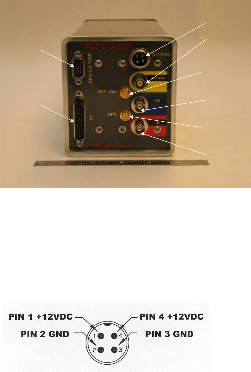
3.2.2.1 DC Power Input
The MCC-6120 SDR requires a power source that can deliver up to 25 amps of pulsed power
(100 msec) out of a +12 V
DC
to +14V
DC
power source. The 25 amp power demand will cause a
voltage drop to occur at the transmitter input, resulting in reduced transmit power, unless the
power cable to the source is sized appropriately. MCC recommends using two #16 AWG wires
for both the power and ground and a cable length that does not exceed 10 feet. If a longer cable
is required use #14 AWG. MCC provides a standard 6 foot power cable with lugs for connecting
to a 3/8” battery post (Part No. 14001350-01).
The power connector pins are as follows:
The voltage at pins 1 and 4 should not drop by more than 2V
DC
during transmission.
I/O Port
DC Power
Input
GPS Antenna
Port
Ethernet & USB
Ports
900 MHz
(UHF)
Antenna Port
[MCC-6100 only]
802.11(b)
Antenna Port
Low Band
Antenna
Port
High Band
Antenna
Port
PRELIMINARY
FCC ID: BIB61201001
INTALLATION 3-7
PRELIMINARY
MCC-6120 SDR Packet Data Radio Network
I/O Port
(44 Pin)
Operator Port
(9 Pin)
Aux Port
(9 Pin)
Data Port
(9 Pin)
Sensor Port
(25 Pin)
3.2.2.2 LB/HB Connectors
Connect the Low Band VHF and High Band VHF antenna cables to the two BNC RF
connectors, being careful to observe the proper frequency bands. Use double-shielded coax for
all connections. RG-223 (double-shielded) may be used for cable lengths under 30 feet for the
low band and high band antenna. Use a double-shielded cable RG-214 for lengths up to 100 feet
for the low and high bands. Refer to Section 3.1.4 for coax cable losses at the various frequency
bands.
3.2.2.3 GPS Antenna
Connect an external GPS antenna to this SMA connector on the front panel when the internal
GPS receiver is used. Note: GPS antennas have a built in amplifiers that require a DC voltage
(3-5 V) on the center conductor.
3.2.2.4 802.11(b)
Connect an external 802.11(b) antenna to this reverse-SMA connector on the front panel. Use
the Antenex TRA24003P 3dB omni directional antenna for the 802.11(b) antenna. Avoid
excessive cable lengths that would induce >3 dB cable loss from the antenna to the radio. It is
recommended that LMR 240 Ultra Flex be used for cable runs up to 20 feet. If longer runs are
required, use the LMR 400 Ultra Flex cable.
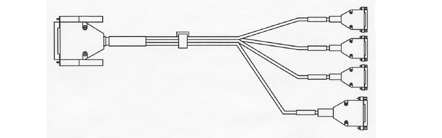
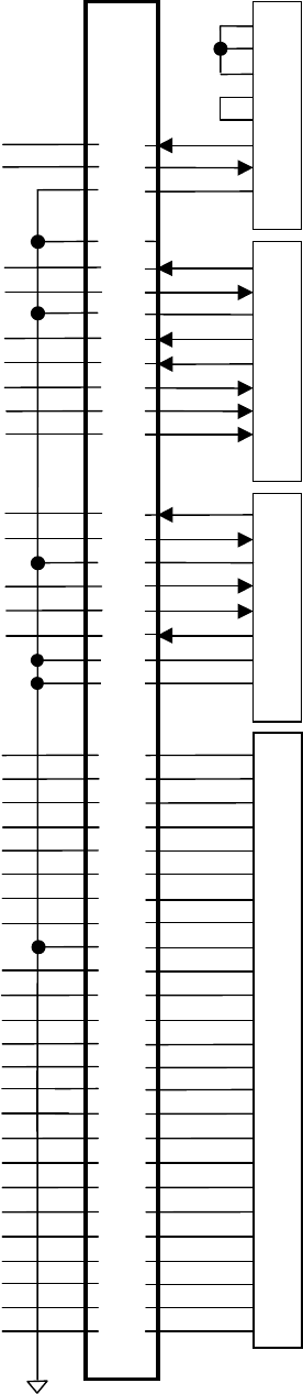
3.2.2.5 I/O Port
The 44 pin I/O connector on the front panel includes three RS-232 ports and one Sensor port.
MCC provides a standard cable harness that breaks out these four ports as shown below:
MCC PART NO. 14001352-01
PRELIMINARY
FCC ID: BIB61201001
INTALLATION 3-8
PRELIMINARY
MCC-6120 SDR Packet Data Radio Network
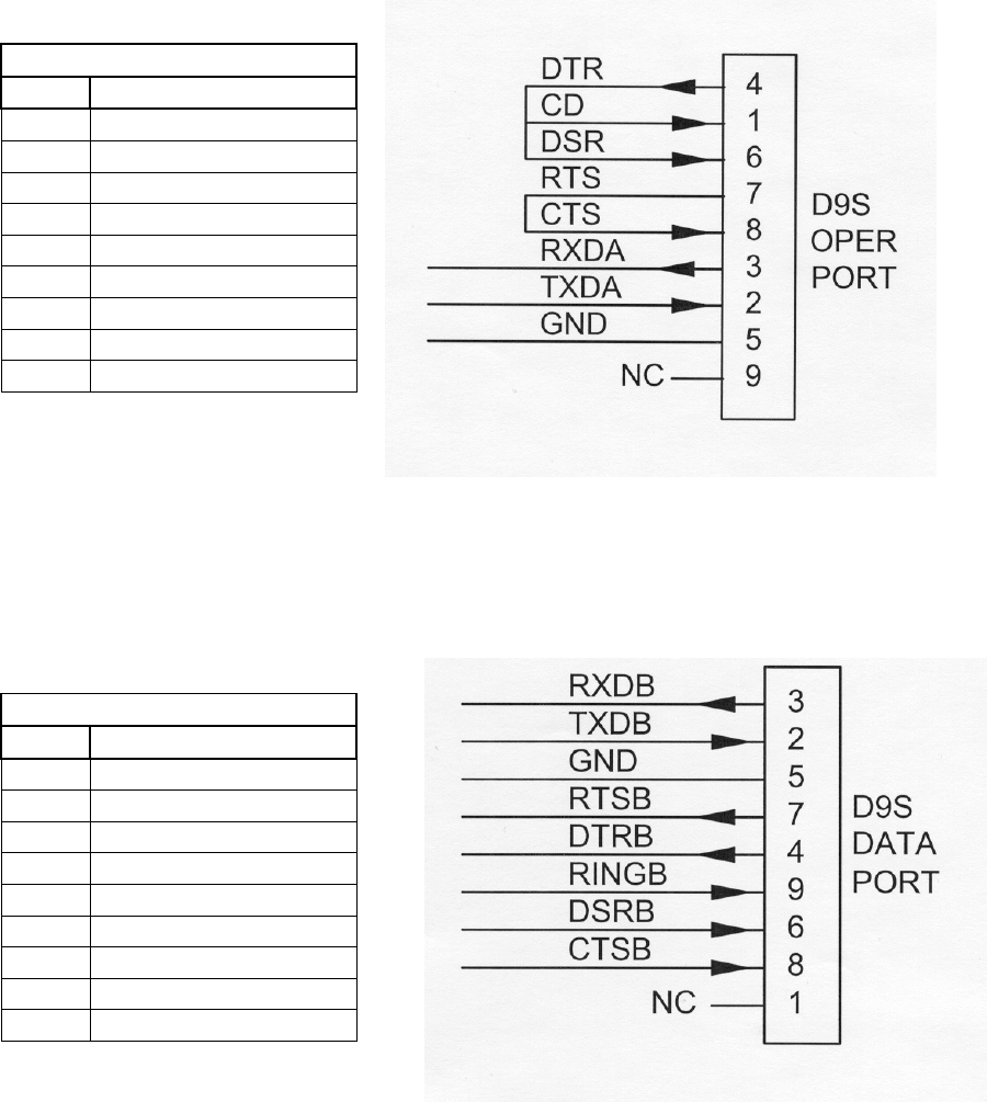
3.2.2.5.1 Operator Port
The Operator Port is normally connected to a local operator terminal. Use a standard RS-232
cable with a 9-pin male D connector.
OPERATOR PORT – 9S
Pin Signal
1 CD
2 Tx Data
3 Rx Data
4 DTR
5 Ground
6 DSR
7 RTS
8 CTS
9 Not Used
3.2.2.5.2 Data Port
The Data Port may be used for connecting to a data logger, GPS receiver or other serial input
device. Use a standard RS-232 cable with a 9-pin male D connector.
DATA PORT – 9S
Pin Signal
1 Not Used
2 Tx Data
3 Rx Data
4 DTR
5 Ground
6 DSR
7 RTS
8 CTS
9 Ring
PRELIMINARY
FCC ID: BIB61201001
INTALLATION 3-9
PRELIMINARY
MCC-6120 SDR Packet Data Radio Network
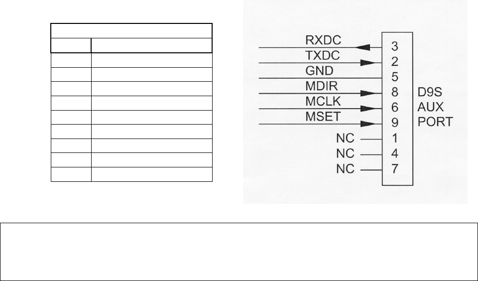
3.2.2.5.3 Auxiliary Port (AUX)
The AUX PORT may be connected to a GPS receiver or other serial input device. Use a
standard RS-232 cable with a 9-pin male D connector. This port is also used for interfacing to
MCC test equipment (pins 6, 8, and 9).
AUX PORT – 9S
Pin Signal
1 Not Used
2 Tx Data
3 Rx Data
4 Not Used
5 Ground
6 MCLK (TTL)
7 Not Used
8 MDIR (TTL)
9 MSET (TTL)
IMPORTANT
The AUX port connector has three extra pins (pins 6, 8, and 9) whose signals do not conform to
the RS-232 standard. These are for MCC test purposes. These pins will NOT interfere with a
normal 3-wire RS-232 connector (pins 2, 3, and 5).
3.2.2.5.4 Sensor Port
The Sensor port is used as a general purpose Supervisory Control and Data Acquisition
(SCADA) interface requiring limited I/O in lieu of a full data logging capability. Use a mating
cable with a 25-pin male D connector for access to the various functions. For convenience, this
cable may be routed to a terminal block for interfacing to the various sensors and other external
devices.

PRELIMINARY
FCC ID: BIB61201001
INTALLATION 3-10
PRELIMINARY
MCC-6120 SDR Packet Data Radio Network
SENSOR PORT
Pin Signal
1 Optocoupled input #1 positive
2 (no connection)
3 Optocoupled input #2 positive
4 Optocoupled input return
5 Optocoupled input #3 positive
6 (no connection)
7 Optocoupled input #4 positive
8 (no connection)
9 Ground
10 MIC_HI
11 MIC_LO
12 Push-To-Talk
13 RX_AUDIO1
14 RX_AUDIO2
15 MUTE
16 Switched +12V (0.5A maximum)
17 Analog Input #1 ( 0 to 5 V) ±0.5%
18 Analog Input #2 ( 0 to 5 V) ±0.5%
19 Analog Input #3 ( 0 to 5 V) ±0.5%
20 Analog Input #4 ( 0 to 5 V) ±0.5%
21 Analog Input #5 ( 0 to 5 V) ±0.5%
22 Analog Input #6 ( 0 to 5 V) ±0.5%
23 +5V Reference
(10mA for sensor excitation)
24 +12V (0.5A maximum)
25 Detected RF Test Point
1
2
3
4
5
6
7
8
9
10
11
12
13
14
15
16
17
18
19
20
21
22
23
24
25
IN1+
NC
IN2+
IN–
IN3+
NC
IN4+
NC
GND
MIC_HI
MIC_LO
PTT
R X _A U D I O 1
R X _A U D I O 2
MUTE
+12Vsw
ADC1
ADC2
ADC3
ADC4
ADC5
ADC6
+5VREF
+12V
DETRF
D25S
SENSOR
PORT
PRELIMINARY
FCC ID: BIB61201001
INTALLATION 3-11
PRELIMINARY
MCC-6120 SDR Packet Data Radio Network
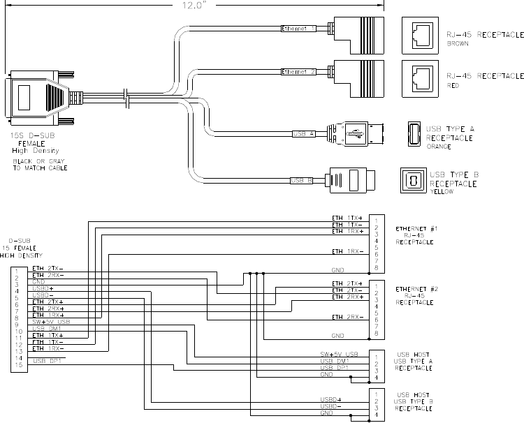
3.2.2.6 Ethernet/USB Connector
The SDR has two Ethernet Network two independent Interface Adaptors and two USB adaptors.
Connections to these adaptors are made thru a 15 pin sub miniature D connector located on the
front panel. An interface cable (provided by MCC) is used to break these connections into
standard RJ 45 plugs for the Ethernet signals and a standard USB Host connector for the USB
Host, and a standard USB Device connector for the second USB port. The Host port is used to
plug memory sticks and camera devices into. The second USB port allows the SDR to operate as
a USB Host, so it can be used to connect a laptop into for purposes of programming the radio.
Ethernet-USB Connectors
PRELIMINARY
FCC ID: BIB61201001
INTALLATION 3-12
PRELIMINARY
MCC-6120 SDR Packet Data Radio Network
DS9
OPERATOR PORT
4
1
6
7
8
3
2
5
9
RXDA
TXDA
GND
24
23
4
DTR
CD
DSR
RTS
CTS
D9S
AUX PORT
3
2
5
8
6
9
4
7
1
33
22
10
28
12
13
MCLK
MDIR
GND
RXDC
MSET
TXDC
GND
GND
8
27
D9S
DATA PORT
3
2
5
7
4
9
6
8
1
7
21
8
32
36
34
35
31
CTSB
DSRB
RINGB
DTRB
RTSB
GND
TXDB
RXDB
-
1
I/O PORT (44 PIN)
D25S
I/O PORT
1
2
3
4
5
6
7
8
9
10
11
12
13
14
15
17
18
19
20
21
22
23
16
24
25
IN1+
19
20
18
3
1
2
16
17
25
15
14
29
11
26
9
38
39
40
37
42
41
30
43
44
5
NC
NC
ADC5
ADC2
+12V
DET RF
GND
RX_AUDIO2
IN–
GND
IN4+
ADC6
ADC4
MIC_HI
MIC_LO
RX_AUDIO1
PTT
IN2+
IN3+
ADC3
GND
+5V
REF
+12V
SW
ADC1
MUTE

PRELIMINARY
FCC ID: BIB61201001
INTALLATION 3-13
PRELIMINARY
MCC-6120 SDR Packet Data Radio Network
3.3 Power-Up Sequence
IMPORTANT
Before applying power to the MCC-6120 SDR, check all connections between the MCC-6120
SDR and the external equipment (power, antenna, operator terminal, and data logger). Refer to
Section 3.2.3 for cabling instructions.
3.3.1 Connect Operator Terminal
Connect a laptop or an operator terminal, with XTERMW installed and running, to the Operator
Port. XTERMW is an MCC windows-based terminal emulation program designed for
interfacing with MCC products. The operator terminal must be programmed with the same
configuration parameters as the Operator Port.
The Operator Port of the MCC-6120 SDR is programmed with the following factory default
configuration at the time of shipment:
Baud rate 9600 Parity none
Data bits 8 Protocol ASCII
Stop bit 1 Flow control none
3.3.2 Power Connection
Power up the MCC-6120 SDR by applying +12VDC to the power connector.
NOTE
When the unit transmits, it will draw up to 20 amps; therefore, review section 3.2.3.1 for proper
cabling to the power source. The voltage drop at the input connector during transmission should
be less than 2 V
DC
for proper operation of the unit. Verify this during the Operational Test
Procedure in Section 3.4.
When power is initially applied to the MCC-6120 SDR, or after a software boot or hardware
reset, the following message will be displayed:
MCC-6120 SDR PACKET DATA RADIO
(c) Copyright 2005 Meteor Communications Corp.
All Rights Reserved
S/W Part Number P1101-00-00 MCC-6120 Version 1.14 11/05/05
S/W Part Number P1102-00-00 DSP SDR Version 1.10 07/14/04
S/W Part Number P1103-00-00 DSP FPGA Version 4 07/14/04
S/W Part Number P1121-00-00 Flexbus FPGA Version 7 11/03/05
* Part Number, Version Number, and date vary according to a particular radio’s Firmware.
PRELIMINARY
FCC ID: BIB61201001
INTALLATION 3-14
PRELIMINARY
MCC-6120 SDR Packet Data Radio Network
At this time all configuration data is loaded from Program Memory into RAM. This data will
remain in RAM until power cycled.
This is the type of message that should be displayed when you first apply power to the unit
during a field installation, and for each subsequent power cycle of the radio.
After power is applied to the radio all parameters that were entered and saved during the
previous session will be reloaded from Flash2 memory.
If you want to load factory defaults, power cycle the unit while holding the lower case f key
down. After about 10-15 f’s are displayed, release the key and you should see the following
message:
+fffffffffffffffffffffffffff
Ver 1.0
SDR Boot... (Entry due to operator request)
1.. Factory Default
9.. Launch Application
Enter a 1 followed by carriage return to restart with factory default parameters.
Enter a 9 to restart the application without changing the stored parameters.
If you restart with factory defaults, the proper script file must be re-entered into the MCC-6120
SDR using XTERMW. (Refer to Section 3.3.3.5 for more information on using script files.)
If you do not have a script file to load you can go through the following procedure to manually
start the unit.
3.3.3 Initialization Procedures
The following initialization procedures should now be performed in the order they are given
below.
3.3.3.1 Verify Device Type
The MCC-6120 SDR must be programmed to operate as a particular device type, such as Remote
Station, Repeater, or Base, depending on your network configuration. The device type is
normally set at the factory prior to shipment to ensure proper integration with your network.
Use the following command to display what device type the unit is configured as:
DEVICE [ENTER]

PRELIMINARY
FCC ID: BIB61201001
INTALLATION 3-15
PRELIMINARY
MCC-6120 SDR Packet Data Radio Network
Always check with your System Administrator to determine which device type your unit should
be configured as.
For example, if the device should be a Remote Station and it is not currently configured properly,
you can change the device type, as follows:
DEVICE,REMOTE [ENTER]
SAVE [ENTER]
CAUTION
Do not change the device type unless told to do so by your System Administrator.
Changing the device type can make your unit cease operating and can impact
communications throughout the entire network.
3.3.3.2 Verify ID Number
Every MCC unit is programmed at the factory with a 16-bit unit ID. To display the unit ID
number on the operator terminal, enter:
ID [ENTER]
Contact your System Administrator to make sure this ID is registered in the network
configuration database. Under some circumstances the ID may have to be changed on-site. This
can only be done if the ID is not locked.
CAUTION
ID changes must be coordinated with both MCC and your System Administrator. Failure
to do so may result in data or messages being misrouted or lost.
If the site is equipped with a CIM (Configuration Information Module), the ID for the
MCC-6120 will be set from the CIM.
3.3.3.3 Verify Channel Frequency
The MCC-6120 SDR is programmed at the factory with the authorized frequencies to be used on
a specific channel in your network. These channels and frequencies are stored in Parameter
memory and cannot be changed. Verify that the correct channel and frequency is configured by
entering the command:
CHANNEL [ENTER]
or CHAN [ENTER] for short cut

PRELIMINARY
FCC ID: BIB61201001
INTALLATION 3-16
PRELIMINARY
MCC-6120 SDR Packet Data Radio Network
This shows you the active or “primary” channel number and TX and RX frequency pair, plus up
to 20 additional frequency pairs for channels that may be programmed at the factory.
For example, the following table could be displayed:
+chan 11/14/05 15:11:26
Primary Channel TX mhz RX mhz Mod-Val
01 44.5800 44.5800 1
11/14/05 15:11:26 Channel Table:
Channel TX mhz RX mhz Mod-Val
>01* 44.5800 44.5800 1
CAUTION
Do not change the frequency pair unless told to do so by your System Administrator.
Changing the frequency pair can make your unit stop communicating with the network.
3.3.3.4 Select Site Name
A descriptive name may be given to the site where the MCC-6120 SDR is being installed. The
selected site name must be coordinated with your System Administrator. To enter a site name
use the following command:
SITE NAME, nnnnnn [ENTER]
where: nnnnnn = maximum of 32 alpha-characters
CAUTION
Please double-check the site name entry for correct spelling and spacing. Data from a site
with an incorrect site name will be mishandled or misrouted by the Host. An incorrect site
name can result in significant effort to recover misrouted data.
3.3.3.5 Enter Script Files
The appropriate Script File is usually programmed into the MCC-6120 SDR at the factory prior
to shipment. If the appropriate Script File has already not been entered, a new file can be loaded
from your operator terminal using XTERMW software. There is one Script File that uniquely
programs the MCC-6120 SDR to operate as a Remote Station in your specific or MeteorComm
network.
NOTE
If the site is equipped with a CIM (Configuration Information Module), the MCC-6120 will
automatically be scripted from the CIM.
PRELIMINARY
FCC ID: BIB61201001
INTALLATION 3-17
PRELIMINARY
MCC-6120 SDR Packet Data Radio Network
The procedure for loading the Script File is described below:
1. Install the MCC-6120 SDR MeteorComm CD (or diskette), with the Script File on it into
your operator terminal, and load the Script File into your XTERMW\XTS subdirectory.
2. Start XTERMW and open a connection at the correct baud rate and COM port (typically
COM1, 9600 baud). All other parameters are defaults.
3. From the Scripts drop-down menu in XTERM, choose Execute Script.
4. Select the appropriate Script File in the XTERM subdirectory. Double-click the file name to
start execution.
The commands in the Script File are executed one at a time until the end of the file is reached.
Press the “up arrow” key to scroll up and review the command responses. If any commands
result in BAD COMMAND, BAD PARAMETER, or a similar message, the Script File may
have an error in it. If so, the script file needs to be corrected. Contact MCC or your System
Administrator for a replacement.
You may verify that the correct configuration file has been loaded by entering the three
commands: ASSIGN, SNP, and CONFIG.
THIS COMPLETES THE INTIALIZATION PROCEDURE

PRELIMINARY
FCC ID: BIB61201001
INTALLATION 3-18
PRELIMINARY
MCC-6120 SDR Packet Data Radio Network
3.4 Operational Test Procedure
3.4.1 RF Test
A very thorough RF test can be made by entering the command TEST [ENTER]. TEST causes
the processor to turn the transmitter ON and measures the forward and reverse RF power that is
being transmitted. It also measures the battery voltage under load and the antenna noise voltage.
The following response will be displayed on the operator terminal:
syncs xmits acks pwr-fwd pwr-rev v-bat det-rf resets
xxxx yyyy zzzz aaaa bbbb ccc ddd eee
where: xxxx = # of sync patterns received from the master station.
yyyy = # of transmissions made by the MCC-6120 SDR.
zzzz = # of acknowledgements received from the Master Station.
aaaa = Forward power in watts. This should be greater than 80 watts.
bbbb = Reflected power in watts. This should be less than 5 watts.
ccc = Battery voltage under load (while transmitting). This should be greater
than 10.6 V
DC
.
ddd = Received signal strength in dBm. This will normally be the noise level
at the antenna and should read about –120.
eee = Number of times the radio has rebooted.
NOTE
The forward RF power should be at least 80 watts when operating at Low Band VHF, and 25
watts when operating in High Band VHF if the battery voltage is normal. If it is lower than these
values check for proper cabling to the power source (see Section 3.2.2.1.).
If the reverse RF power is greater than 5 watts on any channel check the antenna and coaxial
cabling for proper installation.
If both the forward and reverse power are low, the transmitter may be automatically shutting
down due to an antenna VSWR greater than 3:1. Check the antenna and coaxial cabling for
proper installation.
The DET RF value indicates the level of the RF signal plus noise at the antenna in dBM (dB
above or below 1 milliwatt of power). Use the mm,50,dist command to obtain just the noise
value. This noise level should be less than -90 dBM. The lower the number the lower the noise
and the larger the operating range of the unit will be. Refer to Section 3.1 for reducing site noise
conditions.
An overall figure of merit for the link performance is the XMIT to ACK ratio. If this ratio is 3:1
or lower, the overall performance will be very good.
This completes the initialization and power-up sequence of the MCC-6120 SDR.
The unit is now ready for operation.