MetroTel of Minnesota MT9104RTM Cellular Tank Monitor User Manual WRMS Residential LTE Cellular Tank Monitor Operation Manual RevB 2017 12 13

MetroTel Corp of Minnesota Cellular Tank Monitor WRMS Residential LTE Cellular Tank Monitor Operation Manual RevB 2017 12 13

Contents

WRMS Residential LTE Cellular Tank Monitor - Operation Manual RevB - 2017-12-13
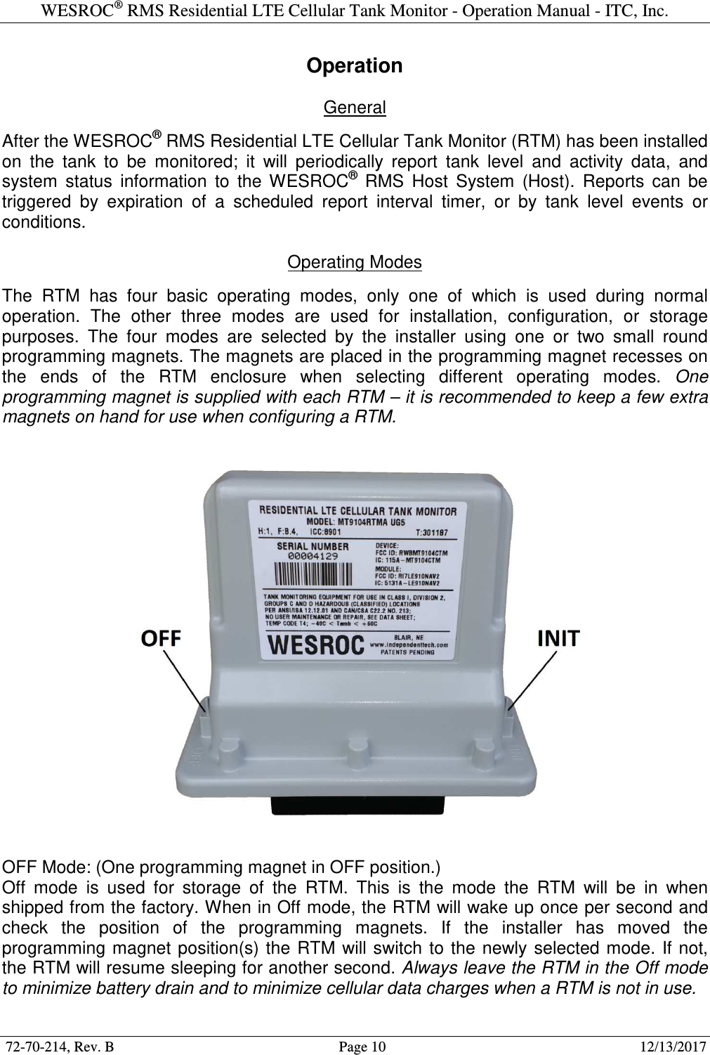
72-70-214, Rev. B                                                                                                            12/13/2017   WESROC® RMS Residential LTE Cellular Tank Monitor Model MT9104RTM Operation Manual
WESROC® RMS Residential LTE Cellular Tank Monitor - Operation Manual - ITC, Inc.  72-70-214, Rev. B                                        Page 2                                                        12/13/2017               This page intentionally left blank.
WESROC® RMS Residential LTE Cellular Tank Monitor - Operation Manual - ITC, Inc.  72-70-214, Rev. B                                        Page 3                                                        12/13/2017  Table of Contents Safety Information............................................................................................................................................................ 5 Hazardous Environments ........................................................................................................................... 5 Battery Replacement .................................................................................................................................. 5 Radio Frequency Exposure ........................................................................................................................ 5 Compliance Information ............................................................................................................................ 5 Overview............................................................................................................................................................................ 6 Device Characteristics ............................................................................................................................... 6 Installation ................................................................................................................................................. 6 Power ......................................................................................................................................................... 6 Installation ........................................................................................................................................................................ 7 Mounting Location .................................................................................................................................... 7 Tank Gauge ............................................................................................................................................... 7 Cellular Signal ........................................................................................................................................... 7 Host Information........................................................................................................................................ 8 Installation Steps........................................................................................................................................ 8 Operation .........................................................................................................................................................................10 General .....................................................................................................................................................10 Operating Modes ......................................................................................................................................10 OFF Mode: ...............................................................................................................................................................10 NORMAL Mode: .....................................................................................................................................................11 INITIALIZATION Mode: .......................................................................................................................................11 CONFIGURATION Mode: .....................................................................................................................................11 Reporting To Host ....................................................................................................................................11 Tank Level Measurement .........................................................................................................................12 Tank Level Events and Conditions ...........................................................................................................12 Tank Fill Event: .......................................................................................................................................................12 Tank Draw Event: ....................................................................................................................................................12 Tank Level Change Event: .......................................................................................................................................12 Tank Critical High Condition: .................................................................................................................................12 Tank Warning High Condition: ...............................................................................................................................12 Tank Warning Low Condition: ................................................................................................................................12 Tank Critical Low Condition: ..................................................................................................................................13 Missing Sensor Condition: .......................................................................................................................................13 Low Battery Notification ..........................................................................................................................13 Portable Diagnostic Unit .................................................................................................................................................14 General .....................................................................................................................................................14 PDU Screen Map ......................................................................................................................................14 PDU Screens .............................................................................................................................................15 Logo Screen: ............................................................................................................................................................15 Device List Screen: ..................................................................................................................................................15 Main Menu Screen: ..................................................................................................................................................16 Summary Screen: .....................................................................................................................................................16 System Configuration Screen: .................................................................................................................................17 Application Configuration Screen: ..........................................................................................................................17 Details Screens: ........................................................................................................................................................18 Raw Data Screens: ...................................................................................................................................................18 Command List Screen: .............................................................................................................................................19
WESROC® RMS Residential LTE Cellular Tank Monitor - Operation Manual - ITC, Inc.  72-70-214, Rev. B                                        Page 4                                                        12/13/2017  System Configuration Parameters .................................................................................................................................20 General .....................................................................................................................................................20 Parameter List ...........................................................................................................................................20 Base ID: ...................................................................................................................................................................20 Primary IP Address: .................................................................................................................................................20 Primary IP Port: .......................................................................................................................................................20 Secondary IP Address: .............................................................................................................................................20 Secondary IP Port: ...................................................................................................................................................20 Host Response Timeout: ..........................................................................................................................................20 Maximum Packet Retries: ........................................................................................................................................20 Report Interval: ........................................................................................................................................................20 Low Battery Threshold (mV): ..................................................................................................................................20 Local Display Mode: ................................................................................................................................................21 ISM Transmitter Number: ........................................................................................................................................21 Application Configuration Parameters .........................................................................................................................21 General .....................................................................................................................................................21 Parameter List ...........................................................................................................................................21 Sensor Scaling: ........................................................................................................................................................21 Tank Fill Threshold: ................................................................................................................................................22 Tank Draw Threshold: .............................................................................................................................................22 Critical High Threshold: ..........................................................................................................................................22 Warning High Threshold: ........................................................................................................................................22 Warning Low Threshold: .........................................................................................................................................22 Critical Low Threshold: ...........................................................................................................................................22 Level Change Threshold: .........................................................................................................................................22 Gain Adjust: .............................................................................................................................................................22 Offset Adjust: ...........................................................................................................................................................22 Battery Replacement .......................................................................................................................................................23 Specifications ...................................................................................................................................................................24 Mechanical ...............................................................................................................................................24 Environment .............................................................................................................................................24 Power Source ............................................................................................................................................24 Tank Level Sensor ....................................................................................................................................24 Cellular Radio ...........................................................................................................................................24 ISM Radio ................................................................................................................................................24 Certifications ....................................................................................................................................................................25 Safety ........................................................................................................................................................25 FCC ..........................................................................................................................................................25 Cellular Carrier .........................................................................................................................................25
WESROC® RMS Residential LTE Cellular Tank Monitor - Operation Manual - ITC, Inc.  72-70-214, Rev. B                                        Page 5                                                        12/13/2017  Safety Information  Hazardous Environments  The WESROC® RMS Residential LTE Cellular Tank Monitor (RTM) is designed for safe use in environments containing  hazardous  vapors.  However,  certain  precautions  need  to  be  taken  to  ensure  the  safety  of  the person(s) working with the RTM, the tank, and any associated equipment. TO ENSURE SAFE OPERATION: Install the RTM according to the instructions contained in this WESROC RMS Residential LTE Cellular Tank Monitor Operation Manual.  WARNING!!! Do NOT loosen or remove float gauge from a pressurized tank! Tank decompression can cause serious injury or property damage!  WARNING!!! Do NOT connect the RTM to any apparatus or wiring from another manufacturer! Substitution of components may impair the intrinsic safety of the RTM! Clean only with a damp cloth to prevent the possibility of electrostatic discharge!  Battery Replacement  The RTM uses a field replaceable battery. The battery is a very specific type and should only be purchased from  Independent  Technologies,  Inc.  Use  of  any  other  power  source  will  compromise  the  safety  and/or performance of the RTM and will void the RTM warranty. Dispose of used batteries properly.  The RTM must be moved to a non-hazardous location before opening to replace the battery.  Radio Frequency Exposure  To  ensure  that  exposure  to  hazardous  radio  frequency  radiation  is  prevented,  the  RTM  must  NOT  be installed in a location where humans will be routinely within 20 centimeters of the RTM. To ensure that FCC requirements are met regarding radio frequency exposure, the RTM is NOT to be placed in  operation  where  it  will  be  co-located  with  another  RTM.  Co-location  is  considered  to  be  where  one operating RTM is within 20 centimeters of another operating RTM.  Compliance Information  Changes  or  modifications  not  expressly  approved  by  the  manufacturer  could  void  the  user’s  authority  to operate this equipment. This product meets the applicable FCC Part 15 rules and Industry Canada's license exempt RSSs. Operation is subject to the following two conditions: (1) this device may not cause interference, and (2) this device must accept any interference, including interference that may cause undesired operation of the device. Le présent materiel est conforme aux CNRexempts de licence d'Industrie Canada. Son fonctionnement est soumis  aux  deux  conditions  suivantes:  (1)  cet  appareil  ne  peut  pas  provoquer  d'interférences,  et  (2)  cet appareil  doit  accepter toute interférence,  y compris celles susceptibles de provoquer  le fonctionnement  du dispositive.
WESROC® RMS Residential LTE Cellular Tank Monitor - Operation Manual - ITC, Inc.  72-70-214, Rev. B                                        Page 6                                                        12/13/2017  Overview  Device Characteristics  The  WESROC®  RMS  Residential  LTE  Cellular  Tank  Monitor  (RTM)  is  used  to  remotely monitor the level of the contents of a tank. The tank level and additional event and status information  are  reported  to  the  WESROC®  RMS  Host  System  (Host)  at  scheduled intervals. In addition, the  RTM will report  to the Host  immediately to  track tank  events in real  time.  The  RTM  uses  the  cellular  data  network  and  the  internet  to  transport  this information.   Communication with the Host is always originated by the RTM, but is bi-directional once a data session has been established. This allows for remote configuration of the RTM should the tank monitoring requirements change or in the event that the RTM is moved to another site.  The RTM can also provide a local tank level display capability. The RTM can be configured to  send  radio  data  packets  to  a  nearby  WESROC®  RMS  Base  Unit  (Base  Unit).  Once initialized to the RTM, the Base Unit will provide the customer with a local display of tank level for up to eight tanks (depending on which Base Unit is used). Note  –  the  Residential  RTM  has  reduced  range  when  communicating  with  a  Base  Unit compared to the Industrial CTM.   Installation  A  basic  RTM  installation  is  easily  performed  in  a  few  minutes  by  persons  with  a  basic understanding of the tank equipment to be monitored and of the RTM device itself. Since the  RTM  is  self-contained,  the  complete  installation  can  be  performed  at  the  tank.  No access to the customer’s residence or place of business is required when local tank level display is not needed.  By default, the RTM is configured to monitor the most common type of tanks, but may be re-configured to monitor a wide variety of tank configurations. The RTM may be remotely configured  by  the  Host,  or  may  be  configured  on  site  by using  the  handheld WESROC® RMS Portable Diagnostic Unit (PDU).   Power  The RTM is battery powered, and due to its low power design will provide many years of monitoring before battery replacement is required. The battery may be replaced in the field once the RTM has been moved to a non-hazardous location.
WESROC® RMS Residential LTE Cellular Tank Monitor - Operation Manual - ITC, Inc.  72-70-214, Rev. B                                        Page 7                                                        12/13/2017  Installation  Mounting Location  The  WESROC®  RMS  Residential  LTE  Cellular  Tank  Monitor  (RTM)  is  designed  to  be installed directly on the tank to be monitored. The RTM is connected to the tank gauge by the tank level sensor and sensor cable. The RTM itself may be attached to the tank with the  supplied  mounting magnet. The RTM  may also  be  located a few feet away from  the tank if necessary to improve cellular reception. Versions of the RTM are available with a longer sensor cable to facilitate mounting the RTM further away from the tank.  Tank Gauge  The standard RTM is equipped with a hall-effect based tank level sensor. This sensor is designed to be snapped into a remote ready tank gauge dial. The sensor and dial are part of  the  R3D  dial  and  sensor  system  manufactured  by  Rochester  Gauges.  R3D  dials  are available  for  a  wide  variety  of  tank  and  gauge  types.  The  RTM  is  configurable  to  work correctly with all available types.  Cellular Signal  The RTM must be installed in a location served by 4G LTE (Long Term Evolution) cellular service. The model  MT9104RTMA RTM  is supported  by AT&T and  its roaming partners. The model MT9104RTMV RTM is supported by Verizon and its roaming partners.  The  RTM  has  a  robust  cellular  sub-system,  but  there  are  limits  to  the  capabilities  of the cellular  network  in  general.  As  with  most  wireless  technologies,  cellular  signal  reception can  be  affected  by  obstructions  such  trees,  mountainous  terrain,  buildings,  metal structures, large  vehicles parked  nearby, etc. In  addition,  cellular signal  reception  will be directly  affected  by  the  distance  between  the  RTM  and  the  nearest  cell  tower  with  LTE cellular service.  The best signal reception will be achieved with a line of sight path between the RTM and the cell tower. Obviously, this is rarely the case in the real world, but it should be kept in mind  when  selecting  a  mounting  location  for  the  RTM.  Elevation  can  also  help;  typically performance will increase as the RTM is raised higher above the ground. The orientation of the RTM itself will also affect performance. The RTM should be installed upright, and if possible,  with  the  sensor  cable  exit  from  the  RTM  enclosure  pointed  AWAY  from  the nearest cell tower supporting LTE cellular service.
WESROC® RMS Residential LTE Cellular Tank Monitor - Operation Manual - ITC, Inc.  72-70-214, Rev. B                                        Page 8                                                        12/13/2017  Host Information  The  customer  information,  installation  location,  and  tank  configuration  for  the  installation site must be entered into the WESROC® RMS Host System (Host) BEFORE the RTM is installed  on  the  tank.  A  RTM  Installation  Information  Worksheet  outlining  the  required information is included in the box and is also available from your host administrator or from Independent  Technologies,  Inc.  Email  or  fax  the  completed  worksheet  to  the  host administrator before beginning the installation. Installation information can also be called in verbally provided your host administrator considers this an acceptable method.   Installation Steps  Performing  the  installation  steps  in the  order  shown  will  help  ensure  proper operation of the RTM. A large percentage of “trouble sites” are caused by improper installation.  1] If possible, perform a site visit to the location of the tank to be monitored. Determine the size  of  the  tank  and  the  type  of  gauge  on  the  tank.  This  will  help  you  select  the  right equipment to bring with at installation time. This is also a good time to try to determine if you have LTE cellular service available. Access to a cell phone can help with checking for the presence of a usable LTE cellular signal.  2]  Send  a  completed  RTM  Installation  Information Worksheet  to your  host  administrator. Try to do this at least one day BEFORE you intend to perform the actual installation so that the host administrator has time to enter the information into the Host.  3] If not already done, install the correct remote ready dial or large dial assembly on the tank gauge. This step is covered in more detail in the WESROC® RMS Dial Replacement Guide available from Independent Technologies, Inc.  4] Remove the RTM from the box and make sure it has the right type of sensor and sensor cable for your application. Make sure the small round programming magnet is secured in the  OFF position on  the  RTM enclosure. This  is important to  ensure proper operation of the RTM when you are ready to perform the first report to the Host.  5]  Mount  the  RTM  directly  on  or  near  the  tank  to  be  monitored.  The  maximum  distance from the tank will be determined by the length of the sensor cable on the particular type of RTM that you are using. The RTM may be mounted to the steel surface of the tank using the mounting magnet on the bottom of the RTM. Another option is to mount the RTM to a pole or another nearby structure using a right-angle mounting bracket. Mounting brackets can be obtained from Independent Technologies, Inc.  Try not to place the RTM right next to a vertical metal object such as a tank dome or hood. Metal objects higher than the bottom of the RTM enclosure tend to have a negative effect on cellular signal quality. As mentioned before, the RTM should be installed upright, and if possible,  with  the  sensor  cable  exit  from  the  RTM  enclosure  pointed  AWAY  from  the nearest cell tower supporting LTE cellular service.
WESROC® RMS Residential LTE Cellular Tank Monitor - Operation Manual - ITC, Inc.  72-70-214, Rev. B                                        Page 9                                                        12/13/2017  6]  Connect  the  sensor  at  the  end  of  the  sensor  cable  to  the  remote  ready  dial.  This  is accomplished  by  sliding  the  sensor  into  the  sensor  slot  on  the  top  of  the  dial.  Slide  the sensor from the side towards the center of the dial until it is fully seated. You will hear or feel a small “snap” once it is fully seated. To remove the sensor from the dial, gently lift up on the end of the sensor before attempting to slide it out of the dial.  7] (Optional.) If you are going to be using a WESROC® RMS Base Unit (Base Unit) as a local  display  device,  now  is  the  time  to  initialize  the  RTM  to  the  Base  Unit.  See  section “Operation”  of  this  document  for  details.  The  “Local  Display”  system  configuration parameter on the RTM must be enabled for this feature to work.  8]  This  step  assumes  that  the  installation  site  information  has  already  been entered into the Host and that this particular installation does not require any unusual configuration of the RTM. Remove the programming magnet from the OFF position on the RTM enclosure and step away from the RTM. (Do not degrade the RTM cellular signal quality by leaning over it while it is attempting to report.)  At this time, the RTM will attempt a configuration report to the Host. The report is typically completed  in  under  a  minute,  but  can  take  up  to  4  minutes  to  complete  under  adverse cellular signal conditions.  The  RTM  does  not  provide  any  direct  feedback  regarding  report  success  or  failure; therefore it is highly recommended to make use of a handheld WESROC® RMS Portable Diagnostic  Unit  (PDU)  when  performing  RTM  installations.  The  PDU  will  provide  the installer with a wealth of information regarding report status, tank level status, RTM system status,  and  cellular  network  performance.  See  section  “Portable  Diagnostic  Unit”  of  this document,  or  the  WESROC®  RMS  Portable  Diagnostic  Unit  Operation  Manual  for  more information on operating the PDU.  Another option for checking report status is to have the Host send a text alert message to the installer’s cell phone once a successful report has completed. This of course requires that  the  host  administrator  enter  the  installer’s  texting  address  into  the  Host  before installation time. Once installation is completed, the installer will want to have their texting address taken off of the alert list for this site to prevent the Host from sending the installer future tank activity alerts.  9]  Once  a  successful  report  has  completed,  secure  the  sensor  cable  using  appropriate fasteners  (cable  ties,  etc.).  Route  the  sensor  cable  to  make  sure  the  cable  will  not  be damaged by a moving object such as a tank dome or hood. Before leaving the installation site, make sure any programming magnets are removed from the RTM enclosure. Normal operating mode is with NO programming magnets installed.
WESROC® RMS Residential LTE Cellular Tank Monitor - Operation Manual - ITC, Inc.  72-70-214, Rev. B                                        Page 10                                                        12/13/2017  Operation  General  After the WESROC® RMS Residential LTE Cellular Tank Monitor (RTM) has been installed on  the  tank  to  be  monitored;  it  will  periodically  report  tank  level  and  activity  data,  and system  status  information  to  the  WESROC®  RMS  Host  System  (Host).  Reports  can  be triggered  by  expiration  of  a  scheduled  report  interval  timer,  or  by  tank  level  events  or conditions.  Operating Modes  The  RTM  has  four  basic  operating  modes,  only  one  of  which  is  used  during  normal operation.  The  other  three  modes  are  used  for  installation,  configuration,  or  storage purposes.  The  four  modes  are  selected  by  the  installer  using  one  or  two  small  round programming magnets. The magnets are placed in the programming magnet recesses on the  ends  of  the  RTM  enclosure  when  selecting  different  operating  modes.  One programming magnet is supplied with each RTM – it is recommended to keep a few extra magnets on hand for use when configuring a RTM.    OFF Mode: (One programming magnet in OFF position.) Off  mode  is  used  for  storage  of  the  RTM.  This  is  the  mode  the  RTM  will  be  in  when shipped from the factory. When in Off mode, the RTM will wake up once per second and check  the  position  of  the  programming  magnets.  If  the  installer  has  moved  the programming magnet position(s) the  RTM  will switch to  the  newly  selected  mode.  If  not, the RTM will resume sleeping for another second. Always leave the RTM in the Off mode to minimize battery drain and to minimize cellular data charges when a RTM is not in use.
WESROC® RMS Residential LTE Cellular Tank Monitor - Operation Manual - ITC, Inc.  72-70-214, Rev. B                                        Page 11                                                        12/13/2017  NORMAL Mode: (No programming magnets.) Normal mode is used while the RTM is monitoring the level of the tank. This is the default operating mode of the RTM once it has  been  installed. While in this mode, the RTM will wake up once per minute and measure the level of the tank contents. The RTM will then go back to sleep or will take the appropriate action if the tank level has changed since the last measurement. Actions may include starting or ending the qualification of a tank level event,  reporting  a  tank  level  event  to  the  Host,  or  reporting  to  the  Host  at  a  scheduled report  time.  While  in  Normal  mode,  the  RTM  is  also  constantly  monitoring  itself  for  any conditions that may require reporting to the Host. The RTM will also simulate a WESROC® RMS Tank Transmitter and will send ISM radio data packets to a Base Unit while in this mode if the “Local Display” system configuration parameter has been enabled.  INITIALIZATION Mode: (One programming magnet in INIT position.) Initialization mode  is used for initializing the RTM to a WESROC® RMS Base Unit (Base Unit) before using the Base Unit as a local tank level display device.  Once the RTM has been put into Initialization mode, it will simulate a WESROC® RMS Tank Transmitter and will send an initialization data packet to the Base Unit once every 15 seconds (or sooner if the tank level changes.) The RTM will time out of Initialization mode and will revert to the Normal  operating  mode  after  60  minutes.  This  is  done  to  conserve  battery  life  and  to ensure that the RTM continues reporting to the Host once the installer has left the site. See the operating manual for the type of Base Unit that you are using for instructions on putting the Base Unit into Initialization mode.  CONFIGURATION Mode: (One programming magnet in both OFF and INIT positions.) Configuration  mode  is  used  to  change  one  or  more  of  the  internal  RTM  configuration parameters.  When  in  this  mode,  system  (RTM)  or  application  (tank  level)  operating characteristics can be changed using a PDU.  Changes made with a PDU are reported to the Host once the RTM is returned to Normal mode.  If  field  configuration  is  enabled  in  the Host,  the  Host  will  store  the  changes  to  its configuration database, and will send the changes back to the RTM to confirm acceptance of the changes. If field configuration is not enabled in the Host, the Host will overrule the RTM and will send the previous configuration back to the RTM. The RTM will time out of Configuration  mode  and  return  to  Normal  mode  if  it  has  not  received  a  configuration command from the PDU for 15 minutes. This is done to conserve battery life and to ensure that the RTM continues reporting to the Host once the installer has left the site.  Reporting To Host  The  RTM  reports  to  the  Host  on  a  schedule  determined  by  the  Host  configuration.  The reporting schedule can range from once per day to once per month. The report interval will directly affect battery life as the cellular sub-system is the major consumer of power in the RTM. It is not recommended to leave the RTM configured with a reporting schedule shorter than weekly as it will shorten battery life and may lead to excessive cellular data charges.  In  addition  to  scheduled  reporting,  the  RTM  will  contact  the  Host  to  report  RTM configuration changes, and tank level events.
WESROC® RMS Residential LTE Cellular Tank Monitor - Operation Manual - ITC, Inc.  72-70-214, Rev. B                                        Page 12                                                        12/13/2017  Tank Level Measurement  The  RTM  wakes  up  and  measures  the  level  of  the  tank  contents  once  per  minute.  This enables  the  RTM  to  be  very  responsive  to  changing  tank  level  conditions  and  to  more accurately qualify events such as tank fills or tank draws. The  tank level is  reported  in a number  ranging  from  0  to  99,  representing  the  tank  level  in  percent  full.  This  is  the predominant  measurement  unit  in  the  propane  industry,  and  also  serves  well  when monitoring low pressure fuels such as gasoline, diesel fuel, heating oil, etc.  Tank Level Events and Conditions  The  RTM  tracks  and  qualifies  a  number  of  different  tank  level  events  and  conditions. Qualification  of  a  tank  level  event  or  condition  will  cause  the  RTM  to  report  to  the  Host ahead  of  its  scheduled  report  time.    A  tank  level  event  such  as  a  tank  fill  is  a  one  time event  and  will be  reported  and  then  cleared from  the  tank  status.  A  tank  level  condition such as a low tank level will be reported, but will not be cleared from the tank status until the  condition  is  no  longer  true.  The  following  is  a  summary of  the tank  level  events  and conditions supported by the RTM. The configuration parameters referred to in this section can be referenced in the “Application Configuration” section of this document.  Tank Fill Event: A  tank  fill  event  will  be  qualified  by  the  RTM  when  the  tank  level  increases  by  the configured amount.  Tank Draw Event: A tank draw event will be qualified by the RTM when the tank level has decreased by the configured  amount  within  one  hour.    A  tank draw  event  will  NOT be  qualified  if  the  tank level has dropped to 0% (bad or missing sensor).  Tank Level Change Event: A  tank  level  change  event  will  be  qualified  by  the  RTM  when  the  tank  level  has  moved above  or  below  the  configured  tank  level  change  threshold  since  the  last  report  to  the Host.  This  threshold  can  be  positive  or  negative,  depending  on  if  the  user  is  looking  to track a rising or falling tank level.  Tank Critical High Condition: A  tank  critical  high  condition  will be  qualified  by  the  RTM  when  the  tank  level  has  risen above the configured tank critical high threshold.  Tank Warning High Condition: A tank warning high condition will be qualified by the RTM when the tank level has risen above the configured tank warning high threshold.  Tank Warning Low Condition: A tank warning low condition will be qualified by the RTM when the tank level has dropped below the configured tank warning low threshold.
WESROC® RMS Residential LTE Cellular Tank Monitor - Operation Manual - ITC, Inc.  72-70-214, Rev. B                                        Page 13                                                        12/13/2017  Tank Critical Low Condition: A tank critical low condition will be qualified by the RTM when the tank level has dropped below the configured tank critical low threshold.  Missing Sensor Condition: A  bad  or  missing  sensor  condition  will  be  qualified  by  the  RTM  when  the  tank  level  has dropped  to 0% for a pre-determined amount of time. The qualification of this  condition is not configurable.  Low Battery Notification  A  low  battery  condition  will  not  immediately  trigger  a  report  to  the  Host,  but  it  will  set  a RTM system status flag that will be picked up by the Host at the next scheduled or event report.
WESROC® RMS Residential LTE Cellular Tank Monitor - Operation Manual - ITC, Inc.  72-70-214, Rev. B                                        Page 14                                                        12/13/2017  Portable Diagnostic Unit  General  The  handheld WESROC® RMS  Portable Diagnostic  Unit  (PDU) is  used  to configure and monitor the status of  the WESROC® RMS Residential LTE Cellular Tank Monitor (RTM). This valuable device should be considered an essential part of any installation tool kit. The following is a summary of the sections of the PDU interface that are designed for use with the  RTM.  A  more  detailed  description  of  the  operation  of  the  PDU  can  be  found  in  the WESROC® RMS Portable Diagnostic Unit Operation Manual.  A configuration data packet is required to be transmitted by the RTM before the PDU can be used to configure the RTM or view detailed data from the RTM. The RTM will transmit a configuration  data  packet  before  and  after  each  report  to  the  Host,  when  the  RTM  is placed  in  Configuration  mode,  and  each  time  a  configuration  command  is  received  from the PDU. The RTM must be in Configuration mode to respond to configuration commands sent by the PDU. A configuration command is sent from the PDU to the RTM each time the user  changes  a  configuration  parameter  value  and  leaves  a  configuration  parameter editing screen.   PDU Screen Map  LogoScreenDeviceListScreenMainMenuScreenSummaryScreenConfigSystemScreenConfigApplicationScreenDetailsScreensCommandListScreenParameterEditScreensParameterEditScreensRaw DataScreensCommandExecutionScreens
WESROC® RMS Residential LTE Cellular Tank Monitor - Operation Manual - ITC, Inc.  72-70-214, Rev. B                                        Page 15                                                        12/13/2017  PDU Screens  Logo Screen: This is the first screen displayed when the PDU is powered up. This screen will contain the WESROC® logo, or may contain your company logo if arrangements have been made for a custom logo. Press the right arrow key on the PDU to move to the Device List Screen. This screen will only be displayed once when the PDU is powered on.      Device List Screen: Each line on this screen represents a WESROC® RMS device that has transmitted a data packet in the recent past. The serial number of the device will be displayed on the left side of  the  screen.  A  configuration  data  packet  from  a  RTM  will  be  noted  by  the  “CelTnk”  or “CelMon”  device  label  in  the  middle  of  the  screen.  The  time  since  the  last  transmission from  each  device  is  listed  on  the  right  side  of  the  screen.  Press  the  up  arrow  or  down arrow  keys  to  select  the  desired  device.  Press  the  right  arrow  key  to  move  to  the  Main Menu Screen.
WESROC® RMS Residential LTE Cellular Tank Monitor - Operation Manual - ITC, Inc.  72-70-214, Rev. B                                        Page 16                                                        12/13/2017  Main Menu Screen: This  screen  contains  a  list  of  screens  that  can  be  selected  depending  on  what  type  of action  you  want  to  take.  Press  the  up  arrow  or  down  arrow  keys  to  select  the  desired screen. Press the right arrow key to move to the selected screen. Press the left arrow key to return to the Device List Screen.      Summary Screen: This  screen  contains a  quick  snapshot  of  the  status  of  the  RTM,  the  tank  level,  and  the cellular  network  conditions  during  the  last  report  to  the  Host.  Press  the  left arrow  key  to return to the Main Menu Screen.
WESROC® RMS Residential LTE Cellular Tank Monitor - Operation Manual - ITC, Inc.  72-70-214, Rev. B                                        Page 17                                                        12/13/2017  System Configuration Screen: This  screen contains a  list of  RTM  system configuration parameters. Press the  up arrow and down arrow keys to select a configuration parameter to change. Not all of the system configuration parameters are visible on the screen at the same time. Press the right arrow key to  move  to the selected  configuration  parameter  editing  screen. Press the left  arrow key to return to the Main Menu Screen.      Application Configuration Screen: This screen  contains a list of application (tank level) configuration parameters. Press the up arrow and down arrow keys to select a configuration parameter to change. Not all of the application configuration parameters are visible on the screen at the same time. Press the right arrow key to move to the selected configuration parameter editing screen. Press the left arrow key to return to the Main Menu Screen.
WESROC® RMS Residential LTE Cellular Tank Monitor - Operation Manual - ITC, Inc.  72-70-214, Rev. B                                        Page 18                                                        12/13/2017  Details Screens: This is a  series of screens that can be used to view detailed information about the RTM system status, the tank level status and history, and information about the cellular network during  the  last  report  to  the  Host.  Press  the  up  arrow  and  down  arrow  keys  to  move between  the  various  detail  screens.  Press  the  left  arrow key to  return  to  the  Main  Menu Screen.      Raw Data Screens: This  is  a  series  of  screens  that  can  be  used  to  view the  raw data  contained  in  the  data packets transmitted from the RTM to the PDU. This information will only be useful for very rare and specific diagnostic purposes. Press the up arrow and down arrow keys to move between the various raw data screens. Press the left arrow key to return to the Main Menu Screen.
WESROC® RMS Residential LTE Cellular Tank Monitor - Operation Manual - ITC, Inc.  72-70-214, Rev. B                                        Page 19                                                        12/13/2017  Command List Screen: This screen contains a list of commands that can be used to control or configure the RTM. Press the up arrow and down arrow keys to move between the various commands. Press the right arrow key to execute a command or to configure a parameter on the RTM. Press the left arrow key to return to the Main Menu Screen.    NOTE: A PDU with firmware earlier than version 5.0 will not have a Command List Screen, but will instead show the ‘Ping’ command on the Main Menu Screen. The firmware on most PDUs can be updated to include the Command List Screen.
WESROC® RMS Residential LTE Cellular Tank Monitor - Operation Manual - ITC, Inc.  72-70-214, Rev. B                                        Page 20                                                        12/13/2017  System Configuration Parameters  General  The WESROC® RMS Residential LTE Cellular Tank Monitor (RTM) system configuration parameters  can  be modified  using  the WESROC®  RMS  Portable  Diagnostic  Unit  (PDU). These  configuration  parameters  can  also  be  modified  by  the  WESROC®  RMS  Host System (Host) during a report.  Parameter List  Base ID: Used to identify a particular RTM device in the Host database. Min: 000000000001; Max: 999999999999 Default: 99xxxxxxxxxx; Disable: N/A  Primary IP Address: The IP address used to report to the primary Host. Min: 0.0.0.1; Max: 255.255.255.255 Default: 69.11.190.186 (ITC WESROC Server); Disable: 0.0.0.0 (Do not report.)  Primary IP Port: The IP port number used to report to the primary Host. Min: 1; Max: 65535 Default: 50444 (ITC WESROC Server); Disable: 0 (Do not report.)  Secondary IP Address: The IP address used to report to the backup Host. Min: 0.0.0.1; Max: 255.255.255.255 Default: 69.11.190.186 (ITC WESROC Server); Disable: 0.0.0.0 (Do not report.)  Secondary IP Port: The IP port number used to report to the backup Host. Min: 1; Max: 65535 Default: 50444 (ITC WESROC Server); Disable: 0 (Do not report.)  Host Response Timeout: The maximum number of seconds that the RTM will wait for a response from the Host before sending a data packet retry. Min: 5; Max: 60 Default: 30; Disable: N/A  Maximum Packet Retries: The maximum number of times that the RTM will retry sending a data packet to the Host before terminating a report. Min: 1; Max: 8 Default: 2; Disable: N/A  Report Interval: The number of minutes until the next scheduled report to the Host. Min: 60 (One Hour); Max: 65535 (45.5 Days) Default: 1440 (24 Hours); Disable: N/A  Low Battery Threshold (mV): The low battery threshold for the RTM system battery. Min: 2500; Max: 3600 Default: 2808 (78%); Disable: N/A
WESROC® RMS Residential LTE Cellular Tank Monitor - Operation Manual - ITC, Inc.  72-70-214, Rev. B                                        Page 21                                                        12/13/2017  Local Display Mode: Enable Local Display mode to configure the RTM to transmit ISM radio data packets to a local display device. Disable if not used to maximize battery life. Range: Enable or Disable Default: Disabled  ISM Transmitter Number: Sets the transmitter number of the RTM. The local display device will display this number next to the displayed tank level. This feature is very useful in multiple tank applications. Min: 1; Max: 127 (Maximum of 8 on handheld and current local display devices.) Default: 1; Disable: N/A   Application Configuration Parameters  General  The WESROC® RMS Residential LTE Cellular Tank Monitor (RTM) application (tank level) configuration parameters can be modified using the WESROC® RMS Portable Diagnostic Unit (PDU). These configuration parameters can also be modified by the WESROC® RMS Host System (Host) during a report.  Parameter List  Sensor Scaling: The sensor output scaling to be used to calibrate the RTM to the type of tank and gauge being monitored. Min: 1; Max: 255 (Not all used at this time – see current list below.) Default: 1 (Small horizontal tank dial.); Disable: N/A  1 = Std Horiz (small dial horizontal propane or fuel tank) 2 = Lg Dial (large dial horizontal tank - use on large dials with black Rochester sensor)  3 = 420# Vert (420# vertical propane cylinder) 4 = 200# Vert (200# vertical propane cylinder with Taylor type “A” dial) 5 = Liquid CO2 (vertical liquid CO2 cylinder – do not use, special use only) 6 = Fuel Horiz (small dial horizontal fuel tank – no longer used, use Std Horiz scaling) 7 = Flat (no dial scaling correction – used with hydrostatic RTM on a vertical tank) 8 = 20k Horiz (20k gallon horizontal fuel tank – do not use, special use only) 9 = 4-20mA (monitor 4-20mA industrial current loop – special use only) 10 = ITC LgDial (large dial horizontal tank - use on large dials with ITC Precision Sensor)  13 = RoundHoriz (used with hydrostatic RTM on a round horizontal tank)  14 = GWR Flat (used with GWR sensor on vertical wall tanks) 15 = GWR RndHrz (used with GWR sensor on round horizontal tanks)  16 = 2012 Horiz (small dial horizontal propane or fuel tank w/ dial produced before 1/13)
WESROC® RMS Residential LTE Cellular Tank Monitor - Operation Manual - ITC, Inc.  72-70-214, Rev. B                                        Page 22                                                        12/13/2017  Tank Fill Threshold: The tank fill event qualification amount in percent full. Min: 3%; Max: 95% Default: 10%; Disable: 0%  Tank Draw Threshold: The tank draw event qualification amount in percent full. Min: 3%; Max: 95% Default: 15%; Disable: 0%  Critical High Threshold: The tank critical high condition level in percent full. Min: 5%; Max: 95% Default: 0%; Disable: 0%  Warning High Threshold: The tank warning high condition level in percent full. Min: 5%; Max: 95% Default: 0%; Disable: 0%  Warning Low Threshold: The tank warning low condition level in percent full. Min: 5%; Max: 95% Default: 30%; Disable: 0%  Critical Low Threshold: The tank critical low condition level in percent full. Min: 5%; Max: 95% Default: 15%; Disable: 0%  Level Change Threshold: The tank level change qualification amount in percent full. Set to a negative number to track a tank level decrease; set to a positive number to track a tank level increase. Min: -95%; Max: +95% Default: 0%; Disable: 0%; Invalid: +1 to +4%, -1% to -4%  Gain Adjust: Used to compensate for tank and gauge size mismatches and gauge gain calibration errors. For special applications only - use with caution. Min: -10.00x (Gain of -10.00); Max: +10.00x (Gain of +10.00) Default: +1.00x (Gain of +1.00) Disable: N/A; Invalid: +0.00  Offset Adjust: Used to compensate for gauge offset calibration errors. For special applications only - use with caution. Min: -100.00; Max: +100.00 Default: +0.00; Disable: N/A
WESROC® RMS Residential LTE Cellular Tank Monitor - Operation Manual - ITC, Inc.  72-70-214, Rev. B                                        Page 23                                                        12/13/2017  Battery Replacement  The  WESROC®  RMS  Residential  LTE  Cellular  Tank  Monitor  (RTM)  uses  a  field replaceable  3.6V  lithium  thionyl  chloride  battery  supplied  by  Independent  Technologies, Inc.  The  RTM  operates  on  a  very  small  amount  of  power,  but eventually  the  battery  will need  replacement.  The  RTM  must  be  moved  to  a  non-hazardous  location  before opening  the  enclosure  for  battery  replacement.  The  following  steps  and  photos illustrate how to replace the RTM battery.  1] Remove the six screws from the bottom of the RTM enclosure and remove the bottom half of the enclosure, sliding the circuit board out of the top half of the enclosure.   2] Depress the small tab on the sensor cable connector and remove it from the connector on the circuit board.    3]  Clip  the  cable  tie  securing  the  old  battery  and  remove  the  battery  from  the  battery holder. Place a new battery in the battery holder and secure using a new cable tie. Make  sure  the  battery  is  properly  seated  into  the  holder  and  that  the  polarity markings are correct! Do NOT try to use a 1.5V alkaline or lithium battery!  4] Reconnect the sensor cable, place the circuit board into the upper half of the enclosure, fit the bottom half of the enclosure to the top half, and replace the six enclosure screws. (Make sure the small tab  at the end of the enclosure bottom is properly aligned  with the small notch on the edge of the enclosure top.) Be sure to tighten the screws enough to compress the enclosure gasket and make a weather tight seal, but do not over tighten the screws and strip the threads from the RTM enclosure. (Proper screw torque is about 10 inch pounds.)
WESROC® RMS Residential LTE Cellular Tank Monitor - Operation Manual - ITC, Inc.  72-70-214, Rev. B                                        Page 24                                                        12/13/2017   Specifications  Mechanical    Size:      5.7”L  x  2.5”W  x  5.8”H   Weight:    Approximately 1.0 lbs   Mounting:    Channel magnet or right-angle bracket.   Environment    Storage Temp:  -50C to +70C   Operating Temp:  -40C to +60C   Humidity:    0 to 100%   Power Source    Type:      3.6VDC AA size lithium thionyl chloride battery.         (Available from Independent Technologies, Inc.)   Expected Life:  5 years (reporting once per week).   Tank Level Sensor    Sensor Type:   R3D Hall-Effect (Straight or Right-Angle)   Cable Length:  5, 10, or 30 feet depending on model   Cellular Radio  MT9104RTMA:  5 band LTE (4G), and 2 band UMTS (3G) MT9104RTMV:  2 band LTE (4G) Antenna:    Internal   ISM Radio    Type:      900MHz ISM Band Transceiver (916.48MHz)   Antenna:    Internal
WESROC® RMS Residential LTE Cellular Tank Monitor - Operation Manual - ITC, Inc.  72-70-214, Rev. B                                        Page 25                                                        12/13/2017  Certifications  Safety  The WESROC® RMS Residential LTE Cellular Tank Monitor has been designed for use as Tank Monitoring Equipment in Class I, Division 1, Groups C and D Hazardous (Classified) Locations per UL1604/ANSI/ISA 12.12.01-2000 and CSA C22.2 No. 213-M1987. Temperature Code: T4; Ambient Temperature Range: -40C to +60C;  FCC  The  WESROC®  RMS  Residential  LTE  Cellular  Tank  Monitor  (FCC  ID  number RWBMT9104RTM  and  IC  number  115A-MT9104RTM)  has  been  tested  and  found  to comply with part 15 of the FCC Rules.   Cellular Carrier  The WESROC® RMS Residential LTE Cellular Tank Monitor has been certified for use on the following cellular networks. MT9104RTMA:    AT&T LTE (4G) and UMTS (3G) MT9104RTMV:    Verizon LTE (4G)                    Copyright© 2017  -  Independent Technologies, Inc.  Blair, NE        www.IndependentTech.com        402-426-3700  Do not reproduce without permission.

Navigation menu