Metrol METROLRCK3E002 RC-K3E 3D touch probe system User Manual
Metrol Co., Ltd. RC-K3E 3D touch probe system Users Manual
Metrol >
Users Manual
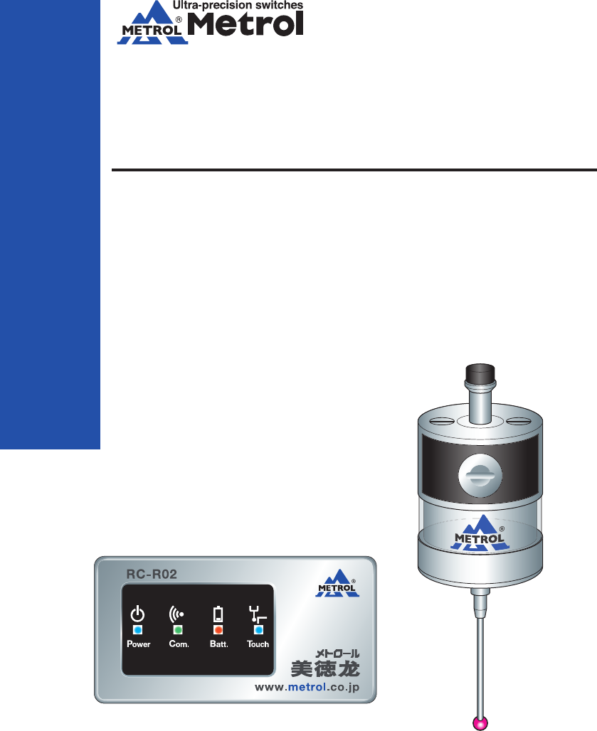
RC-K3E
METROL CO., LTD.
Three-Dimensional
Touch Probes
Instruction Manual
METROL CO., LTD.
1-100 Takamatsu-cho Tachikawa, Tokyo 190-0011 JAPAN
Tel: +81 50 5558 7366 / Fax: +81 42 528 1442
E-mail: touchsensor@metrol.co.jp
TOKYO JAPAN
The specifications and descriptions are subject to change without notice due to improvements in products.
GM-RCK3E-E-K003
INDEX
www.metrol.co.jp
www.metrol.co.jp
1.Before Using
Terms of Warranty . . . . . . . . . . . . . . . . . . . . . . . P1∼2
Usage Precautions . . . . . . . . . . . . . . . . . . . . . . . P3
2.Basic Information
Dimensions RC-K3E . . . . . . . . . . . . . . . . . . . . . . . P5
RC-R02 . . . . . . . . . . . . . . . . . . . . . . . P6
Specifications RC-K3E . . . . . . . . . . . . . . . . . . . . . . . P7
RC-R02 . . . . . . . . . . . . . . . . . . . . . . . P8
3.Wireless Touch Probe
Transmission Range when Combining Probe and Receiver . . . . . P10
Preparations for RC-K3E
1)Finger Attachment . . . . . . . . . . . . . . . . . . . . . . . P11
2)Installing and Replacing the Battery . . . . . . . . . . . . . . . . . . P12
3)Attachment of Probe to Shank . . . . . . . . . . . . . . . . . . . . . . . P13
4)Finger Centering Adjustment . . . . . . . . . . . . . . . . . . . . . . . P14
Receiver Attachment . . . . . . . . . . . . . . . . . . . . . . . P15∼16
Matching Probe and Receiver . . . . . . . . . . . . . . . . . . . . . . . P17
Operating Modes . . . . . . . . . . . . . . . . . . . . . . . P18
4.Maintenance
Cleaning the Probe . . . . . . . . . . . . . . . . . . . . . . . P19
Battery Replacement . . . . . . . . . . . . . . . . . . . . . . . P19
5.Troubleshooting . . . . . . . . . . . . . . . . . . . . . . . P21∼22
6.Parts List . . . . . . . . . . . . . . . . . . . . . . . P23
Made in Malaysia
FCC ID : AORMETROLRCR02
Made in Japan
FCC ID : AORMETROLRCK3E002
This device complies with
Part 15 of the FCC Rules.
Operation is subject to the
following two conditions:
1-this device may not cause
harmful interference. and
2-this device must accept
any interference received,
Including interference that
may cause undesired
operation.
Metrol Co., Ltd.
Model : RC-R02
Power : DC24V
CMIIT ID : YYYY×Bzzzz
Metrol Co., Ltd.
Model : RC-K3E
Power : 3.6V
CMIIT ID : YYYY×Bzzzz
The changes or modifications not expressly approved
by the party responsible for compliance could void
the user’ s authority to operate the equipment.
To comply with the FCC RF exposure compliance
requirements, this device and its antenna must not
be co-located or operating to conjunction with any
other antenna or transmitter.
This device complies with Part 15 of the FCC Rules.
Operation is subject to the following two conditions:
1-this device may not cause harmful interference. and
2-this device must accept any interference received,
Including interference that may cause undesired operation.
■FCC Regulation Notice

■Terms of Warranty
We endeavour to achieve zero claims and complaints rate with respect to product quality assurance.
Although malfunctions are a problem that comes before the warranty and even one should be
prevented, malfunctions cannot be prevented through our efforts alone. We would therefore like
to request that our customers have an understanding of the functions and specifications of
applicable products as indicated in our catalogs, instruction manuals and web site to ensure
that they are used properly under specified conditions.
Furthermore, applicable products are designed and manufactured primarily for general indus-
trial use.
Therefore, we would also like to request our customers to cooperate in employing a safe
design for preventing accidents, fires and the like through providing of fail-safe measures,
preventing operational errors and employing redundant safety designs.
1) Applicable Products
The warranty defined below is applicable to products manufactured and sold by METROL (to
be referred to as the "applicable products").
2) Warranty Period
The warranty for applicable products is valid for one year and three months from the original
delivery dute to the location designated by the customer.
*The initial three months are assumed to be a preparation period until use of the products
following purchase.
3) Range of Coverage
a. A replacement product will be provided on an exchange basis or the malfunctioned product
will be repaired free of charge within the warranty period. if the product is or becomes
defective and that at the sole discretion of METROL, the defectis due to faulty materials or
workmanship.
However, applicable products will not covered by the warranty in the case of the following
malfunctions even within the warranty period.
( I ) Malfunctions occurred due to use of a product in a manner that deviates from
standards, specifications, environments, usage procedures or usage precautions
described in the catalog, instruction manual or specifications.
( II ) Malfunctions having occurred for reasons other than those attributable to the delivered
product.
( III ) Malfunctions having occurred due to modifications or repairs made by someone else
other than the Metrol representative.
(IV) Malfunctions or damage that results from external causes outside our control which
shall include accident fire disaster, other nature disaster or other force majeure.
b. The range of coverage is limited to warranty of the applicable product only, and any other
secondary loss or damage resulting from the malfunction of an applicable product is not
covered by the warranty.
c. Please be aware that charges for service (including installation, de-installation on-site
confirmation and repairs) are not included in the price of products.
4) Applications
Applicable products are designed and manufactured as general-purpose products used in
ordinary industrial environments.
In the case of incorporating an applicable product in an apparatus, machine or system,
please confirm the suitability of the application along with any related standards, regulations
and restrictions.
With respect to the applications indicated below in particular, customers are requested to
conduct necessary tests on an actual product in advance after consulting with the manufac-
turer regarding usage conditions and other details.
a. Applications for which usage conditions or environment are outside those presumed by the
manufacturer or applications unable to be confirmed as being appropriate by the manufac-
turer when using applicable products.
b. Applications likely to have an effect on human life or property (such as nuclear power
equipment, transportation machinery or medical devices), applications used in public
utilities (such as electricity, gas or water lines), or applications applying correspondingly
thereto.
c. Applications in harsh environments (special environments requiring heat resistance, vacuum
and the like)
*Although METROL believes that sound reliability in harsh environments is one of the charac-
teristics of our products, there are still cases in which it is difficult to ascertain actual
circumstances.
Since there is the potential for accidents in such cases, customers are requested to have an
understanding of protective structures, materials and so forth and provide additional covers
and other equipment as necessary.
5) Other Matters
The contents of this catalogue, including specific models and, specifications, and any
other contents, are subject to change without notice at METROL’s sole discretion.
Although the utmost care has been taken in producing this manual, the manufacturer is
not responsible for any damages incurred as a result of clerical or other errors in this
manual.
1.Before Using
1
2
www.metrol.co.jp
www.metrol.co.jp

■Usage Precautions
NOTE
1) Battery
The RC-3KE comes with two 1 / 2AA size lithium metal batteries (non-rechargeable). Please
dispose of used batteries in accordance with laws and regulations relating to the environ-
ment and safety regulations in your area. Do not attempt to recharge these batteries.
When replacing the battery, confirm that the battery is of the recommended or applicable
type, and confirm that the battery is inserted while correctly aligning the electrodes in
accordance with the procedure described in this manual and the indications on the product.
Please refer to the instruction manual of the battery manufacturer for guidelines relating to
specific battery applications, safety and disposal.
・ Please confirm that all batteries are inserted with the electrodes correctly aligned.
・ Do not store batteries in locations subject to direct sunlight or rain.
・ Do not allow the battery to be heated or incinerated.
・ Do not intentionally discharge the battery.
・ Do not allow the battery to be short-circuited.
・ Do not disassemble the battery, subject the battery to excessive pressure, drill holes in the
battery or allow it to be deformed.
・ Take precautions so that the battery is not accidentally swallowed. Store the battery in a
location out of the reach of children.
・ Do not allow the battery to become wet.
2) Glass Window
The RC-R02 has a glass window. In the case the glass window should happen to be broken,
handle the product carefully to prevent injury.
3) Installation Work
Please confirm that the following guidelines are strictly observed at the responsibility of the
person performing installation work to ensure that the product functions properly.
・ Please install while placing the interface at an adequate distance from electrical noise
generation sources such as transformers or servo amplifiers.
・ Connect all 0V / ground connections to a central ground terminal on the machine.
(The grounding and shielded cables of all devices can be connected to ground.)
This is extremely important, and failure to do so can cause the generation of an electrical
potential between the product and ground.
・ Connect all shields as indicated in the user's guide.
・ Place cables at an adequate distance from large-current cables such as motor and other
power cables as well as high-speed data cables.
・ Try to keep cable lengths as short as possible at all times.
4) Product Usage
Use of this product in a manner other than that specified by the manufacturer may cause a
decrease in the guaranteed performance and functions of the product.
1.Before Using
3
4
www.metrol.co.jp
www.metrol.co.jp
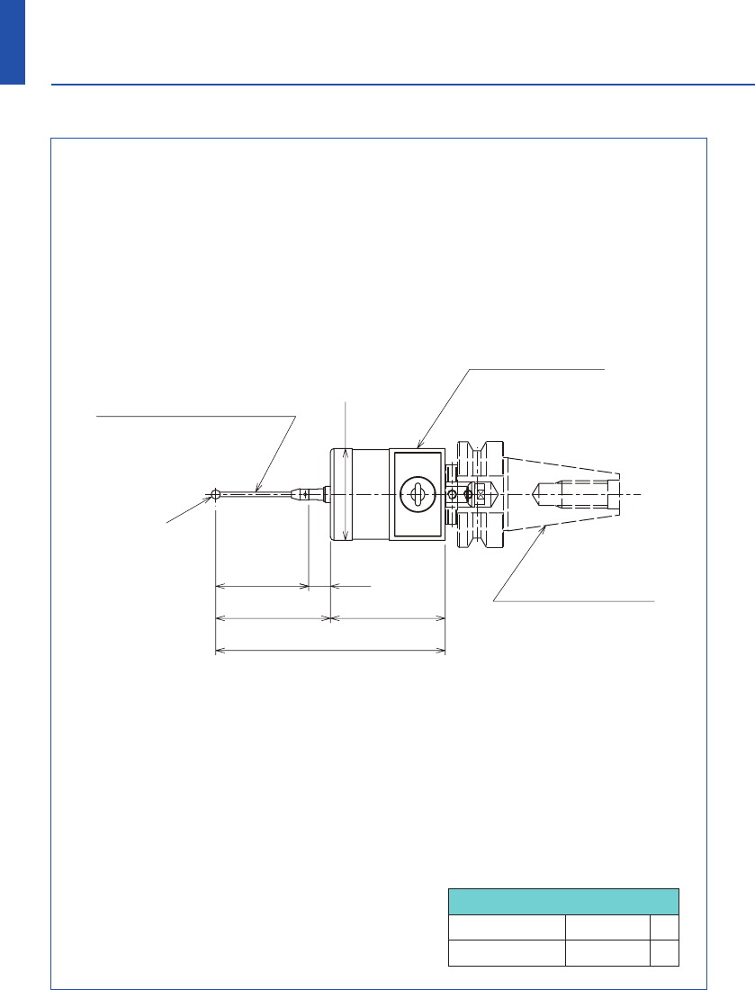
RC-K3E-001-002HJ
(BT30 : H-BT30-001)
■Dimensions
■Dimensions
Finger Overtravel
Finger length ±X/±Y Z
50 7 3
2.Basic Information
5
6
www.metrol.co.jp
www.metrol.co.jp
RC-K3E
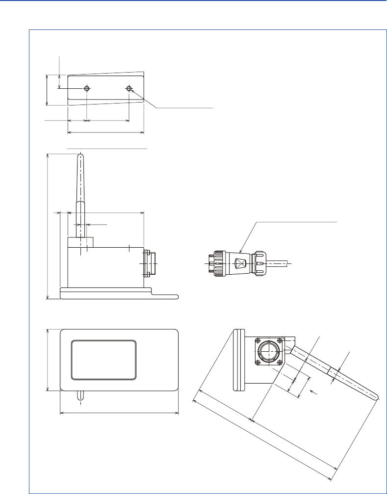
RC-R02
73
140
(189)
(72)(117)
28
15 31.2
φ10
(172)
Output cable
(Standard 5m : DC-R02-050)
990
90
22.5 50
2-M6depth : 8
Mounting surface view
Mounting
surface view
(100)
(50)50
40.5 9.5
φ
4
φ
40
(Standard : F-R40T-405)
Shank
Sensor head
Finger
Compatible with
various specifications.
Compatible with
various specifications.
7.5
(28)
(15)
RC-K3E-001-002HJ
(BT30 : H-BT30-001)
■Dimensions
■Dimensions
Finger Overtravel
Finger length ±X/±Y Z
50 7 3
2.Basic Information
5
6
www.metrol.co.jp
www.metrol.co.jp
RC-K3E
RC-R02
73
140
(189)
(72)(117)
28
15 31.2
φ10
(172)
Output cable
(Standard 5m : DC-R02-050)
990
90
22.5 50
2-M6depth : 8
Mounting surface view
Mounting
surface view
(100)
(50)50
40.5 9.5
φ
4
φ
40
(Standard : F-R40T-405)
Shank
Sensor head
Finger
Compatible with
various specifications.
Compatible with
various specifications.
7.5
(28)
(15)
Main applications Workpiece dimension and centering measurements
in CNC machine tools
Weight (excluding shank) With battery : 290 g
Without battery : 280 g
Signal transmission format GFSK (DSSS) wireless transmission format
No. of channels 37
Wireless frequency 2400 MHz - 2480 MHz
Power ON signal M code (wireless signal)
Power OFF signal M code (wireless signal)
Signal transmission range Max. 15 m
Receiver / interface Receiver antenna-integrated interface
Detected directions 5 directions ±X, ±Y, ±Z
Single direction repeatability 1.0 µm (transmission speed : 150 mm/min)
Max : 2 sigma value (in all directions)
Standard finger measuring pressure
XY : 0.5 N
(
when using 50 mm straight stylus)
Z : 4.5 N
Overtravel XY directions : ±7°
Z direction : 3 mm
Usage environment
(in accordance with
standard BS EN
61010-1 : 2001)
Battery 1 / 2AA lithium-thionyl chloride battery (3.6 V) - 1
Time until battery replacement
After start of low battery indication : approx. 1 hr
Low battery indication
Flashing of battery alarm LED (red)
Dead battery indication Illumination of battery alarm LED (red)
Battery life (reference value) Refer to table below
Waterproof design IEC IP67
Storage temperature -10°C - 70°C
Operating temperature 5°C - 50°C
For indoor use only
Battery During standby 5% use (72 min /day) Continuous use
1 / 2AA lithium-thionyl chloride battery
160 days 125 days 440 hours
■RC-K3E Specifications
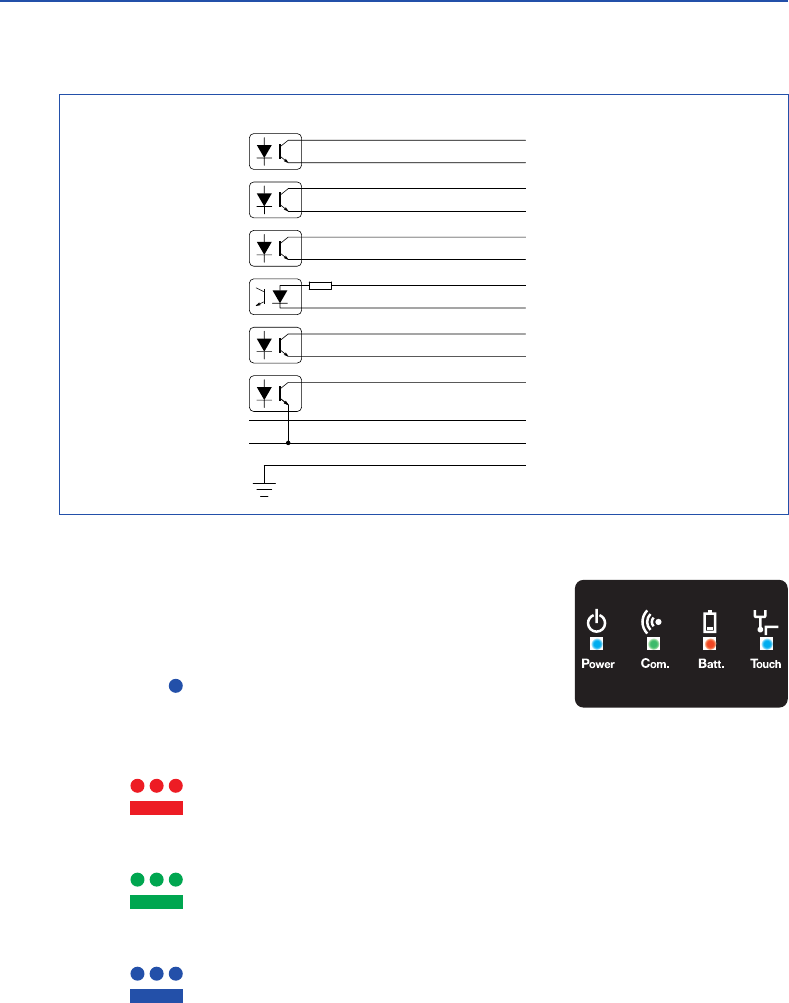
2) LED Display
System status is displayed with four LED shown at right.
・ Touch LED : Indicates the signal output of the touch probe.
OFF : Signal not being received
(touch probe signal output OFF)
: Signal received (touch probe signal output ON)
・ Batt. LED : Indicates battery status of touch probe.
OFF : Battery normal
: Battery must be replaced (low residual charge)
: Battery dead
・ Com. LED : Indicates communication status between touch probe and receiver.
: Communication status decreased or interrupted, or searching for connection
: Normal communication status
・ Power LED : Indicates status of power supply.
: Receiver initiating immediately after machine tool power switched on
: Normal power supply status
■RC-R02 Specifications
1) Wiring Diagram
2.Basic Information
7
8
www.metrol.co.jp
www.metrol.co.jp
BLUE / BLACK
VIOLET
VIOLET / BLACK
GREEN
GREEN / BLACK
WHITE
BROWN
4.7
k
Ω
YELLOW
GREY
ORANGE
RED
BLACK
GREEN / YELLOW
BLUE +24V
PROBE STATUS 1
+24V
LOW BATTERY
+24V
ERROR
MACHINE START +
MACHINE START 0V
SKIP +
SKIP 0V
PROBE STATUS 2b
+24V (12V-30V)
0V
MACHINE GROUND
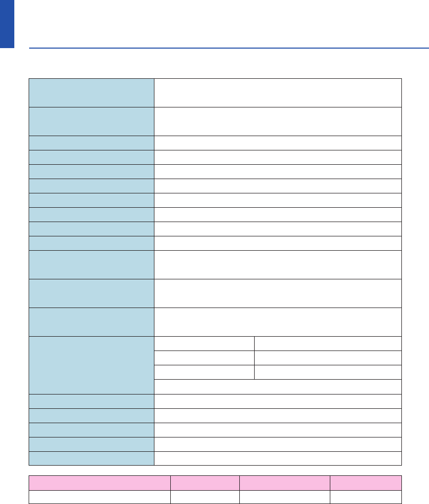
Main applications Workpiece dimension and centering measurements
in CNC machine tools
Weight (excluding shank) With battery : 290 g
Without battery : 280 g
Signal transmission format GFSK (DSSS) wireless transmission format
No. of channels 37
Wireless frequency 2400 MHz - 2480 MHz
Power ON signal M code (wireless signal)
Power OFF signal M code (wireless signal)
Signal transmission range Max. 15 m
Receiver / interface Receiver antenna-integrated interface
Detected directions 5 directions ±X, ±Y, ±Z
Single direction repeatability 1.0 µm (transmission speed : 150 mm/min)
Max : 2 sigma value (in all directions)
Standard finger measuring pressure
XY : 0.5 N
(
when using 50 mm straight stylus)
Z : 4.5 N
Overtravel XY directions : ±7°
Z direction : 3 mm
Usage environment
(in accordance with
standard BS EN
61010-1 : 2001)
Battery 1 / 2AA lithium-thionyl chloride battery (3.6 V) - 1
Time until battery replacement
After start of low battery indication : approx. 1 hr
Low battery indication
Flashing of battery alarm LED (red)
Dead battery indication Illumination of battery alarm LED (red)
Battery life (reference value) Refer to table below
Waterproof design IEC IP67
Storage temperature -10°C - 70°C
Operating temperature 5°C - 50°C
For indoor use only
Battery During standby 5% use (72 min /day) Continuous use
1 / 2AA lithium-thionyl chloride battery
160 days 125 days 440 hours
■RC-K3E Specifications
2) LED Display
System status is displayed with four LED shown at right.
・ Touch LED : Indicates the signal output of the touch probe.
OFF : Signal not being received
(touch probe signal output OFF)
: Signal received (touch probe signal output ON)
・ Batt. LED : Indicates battery status of touch probe.
OFF : Battery normal
: Battery must be replaced (low residual charge)
: Battery dead
・ Com. LED : Indicates communication status between touch probe and receiver.
: Communication status decreased or interrupted, or searching for connection
: Normal communication status
・ Power LED : Indicates status of power supply.
: Receiver initiating immediately after machine tool power switched on
: Normal power supply status
■RC-R02 Specifications
1) Wiring Diagram
2.Basic Information
7
8
www.metrol.co.jp
www.metrol.co.jp
BLUE / BLACK
VIOLET
VIOLET / BLACK
GREEN
GREEN / BLACK
WHITE
BROWN
4.7
k
Ω
YELLOW
GREY
ORANGE
RED
BLACK
GREEN / YELLOW
BLUE +24V
PROBE STATUS 1
+24V
LOW BATTERY
+24V
ERROR
MACHINE START +
MACHINE START 0V
SKIP +
SKIP 0V
PROBE STATUS 2b
+24V (12V-30V)
0V
MACHINE GROUND

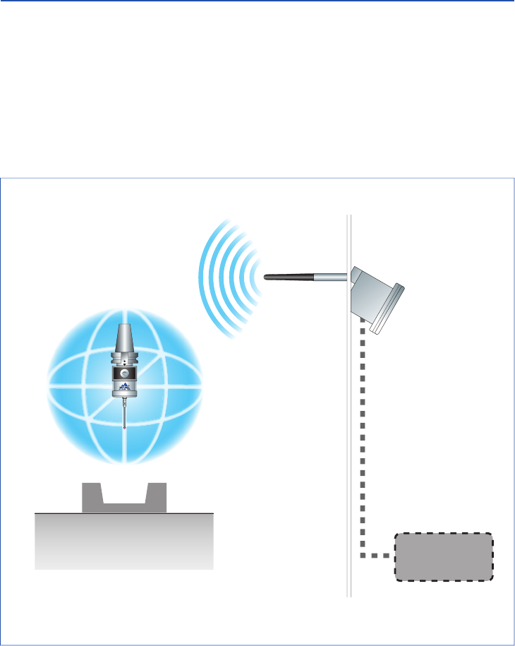
■Transmission Range when Combining Probe and Receiver
Probe and Receiver Installation Locations
Install the probe system at a location that enables the system to cover the communication
range over the entire stroke of the movement axis of the machine. Use the communication
LED display of the receiver as a reference for determining the optimum installation position.
Workpiece
NOTE
9
10
www.metrol.co.jp
www.metrol.co.jp
3D
software
RC-K3E RC-R02
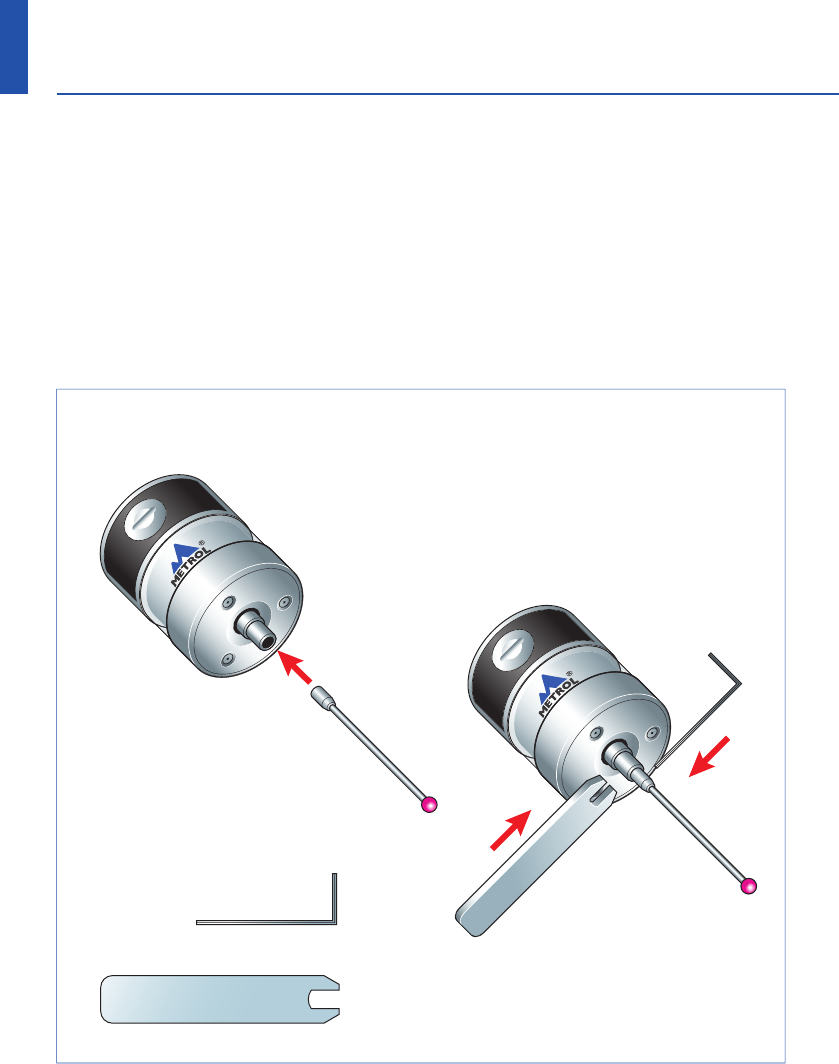
■Preparations for RC-K3E
1) Finger Attachment
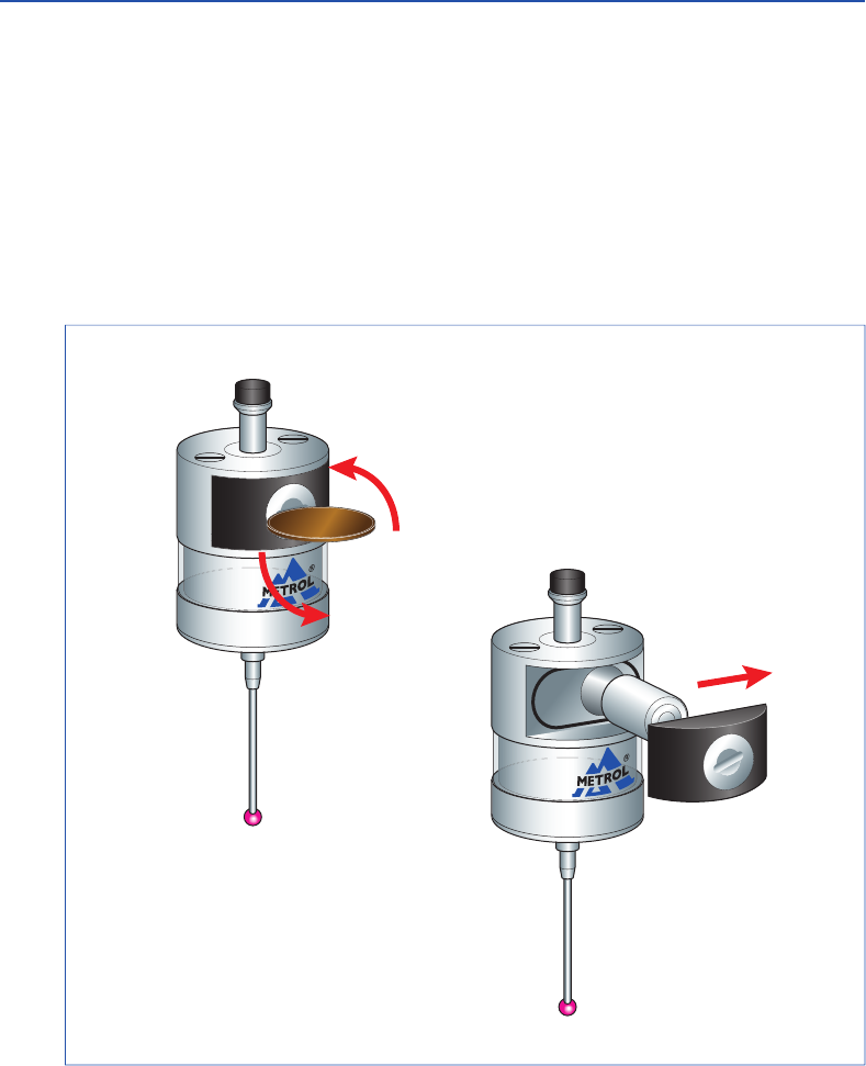
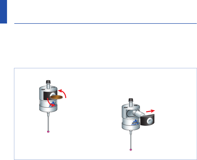
2) Installing and Replacing the Battery
Confirm the alignment of the battery electrodes when inserting the battery. The LED display
will not light if a dead battery is mistakenly inserted into the probe (refer to P18).
Do not allow coolant or cuttings to get inside the battery housing.
After attaching the battery cover, the LED will light for about 10 seconds.
Do not touch the finger while the LED is lit. (The probe will switch to the matching mode if
the finger is touched while the LED is lit. Reinstall the battery if this happens.)
① Remove the battery cover
with a screwdriver or coin.
② Take out the battery.
Hexagonal wrench
0.89 mm
Spanner S907
① Insert the finger.
② Tighten using the hexagonal
wrench and spanner.
3.Wireless Touch Probe
11
12
www.metrol.co.jp
www.metrol.co.jp
■Preparations for RC-K3E
1) Finger Attachment
2) Installing and Replacing the Battery
Confirm the alignment of the battery electrodes when inserting the battery. The LED display
will not light if a dead battery is mistakenly inserted into the probe (refer to P18).
Do not allow coolant or cuttings to get inside the battery housing.
After attaching the battery cover, the LED will light for about 10 seconds.
Do not touch the finger while the LED is lit. (The probe will switch to the matching mode if
the finger is touched while the LED is lit. Reinstall the battery if this happens.)
① Remove the battery cover
with a screwdriver or coin.
② Take out the battery.
Hexagonal wrench
0.89 mm
Spanner S907
① Insert the finger.
② Tighten using the hexagonal
wrench and spanner.
3.Wireless Touch Probe
11
12
www.metrol.co.jp
www.metrol.co.jp
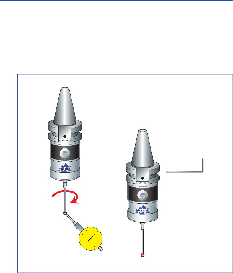
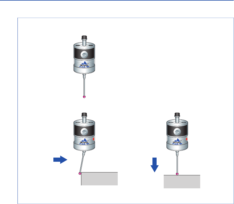
4) Finger Centering Adjustment
Caution: It is necessary to recheck the centering adjustment if the touch probe has been
dropped. Absolutely never strike the probe when adjusting centering.
■Preparations for RC-K3E
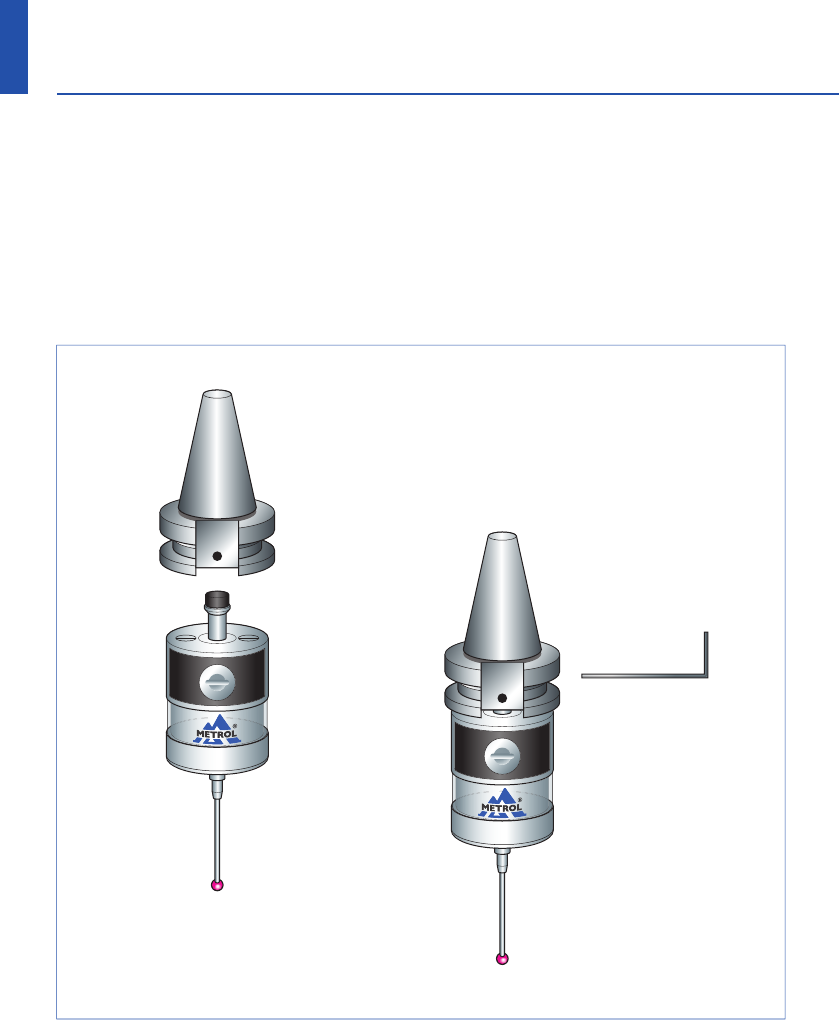
3) Attachment of Probe to Shank
① Attach the shank to the probe body.
② Tighten the set screw with
a hexagonal wrench.
0
20
10 10
20
40 50
30 30
40
① Adjust centering with Lever type dial gauge
or similar tool.
② After adjusting,
tighten the set screw
using a hexagonal wrench.
13
14
www.metrol.co.jp
www.metrol.co.jp
3.Wireless Touch Probe
Lever type dial gauge
4) Finger Centering Adjustment
Caution: It is necessary to recheck the centering adjustment if the touch probe has been
dropped. Absolutely never strike the probe when adjusting centering.
■Preparations for RC-K3E
3) Attachment of Probe to Shank
① Attach the shank to the probe body.
② Tighten the set screw with
a hexagonal wrench.
0
20
10 10
20
40 50
30 30
40
① Adjust centering with Lever type dial gauge
or similar tool.
② After adjusting,
tighten the set screw
using a hexagonal wrench.
13
14
www.metrol.co.jp
www.metrol.co.jp
3.Wireless Touch Probe
Lever type dial gauge
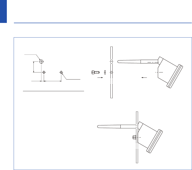
Recommended mounting holes
■Receiver Attachment
■Attachment of Direct Cable
・ Since the connector provides a waterproofing function when connected, insert the connector
securely and tighten the clamp nut.
・ Install the cable at an adequate distance away from electromagnetic noise generation sources.
・ Always make sure to connect the cable to ground when connecting.
15
16
www.metrol.co.jp
www.metrol.co.jp
3.Wireless Touch Probe
NOTE
507.5
31.2
2-φ6.6
φ10.5
X / Y Z
■Matching Probe and Receiver
It is necessary to match the probe and receiver when first installing the system. Matching is
also required only when replacing either the touch probe or the receiver. Matching is not
disabled when the power is turned off or when the battery is replaced. Matching can be
performed anywhere within the range of movement of the system.
■Operating Modes
Note① : Due to the properties of the lithium-thionyl chloride battery, the following series of
problems can occur if the low battery indication is ignored or overlooked.
1. The battery becomes worn down when the probe power is turned on, eventually
preventing the probe from functioning properly.
2. Although the probe may no longer function, if left as is, the power of the probe may
come back on if the battery is restored to a certain degree .
3. The battery becomes dead again and the probe no longer functions.
4. This series of events is repeated .
Note② : When the battery of the touch probe has remained dead (Batt. LED on the receiver is
lit) for 3 hours or more, the entire system no longer functions.
In this case, replace the battery of the touch probe, unplug the cable from the receiver,
and plug in the cable after waiting 10 seconds.
This will reset the system and restore system function.
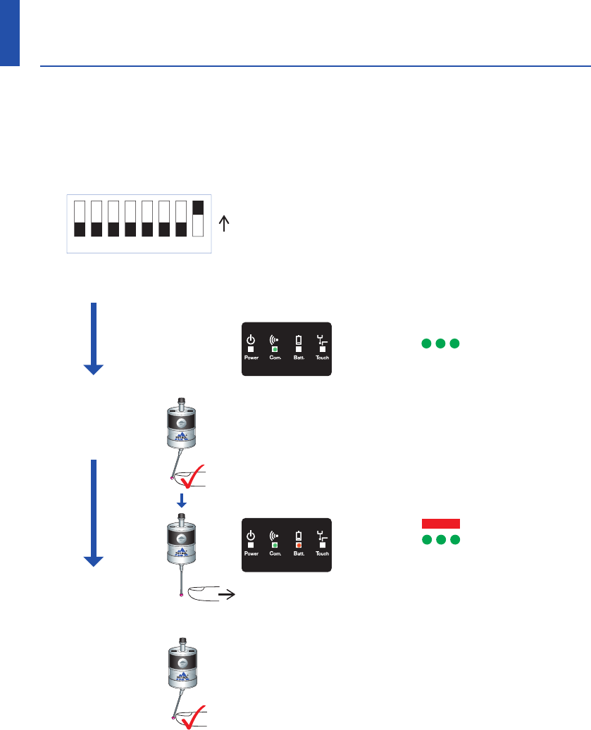
Detailed Diagram of DG SW
ON ・The Com. LED flashes during matching.
・The Batt. LED lights when matching is completed.
・The Batt. LED is turned off by switching off
the digital switch #8 on the receiver.
1) Switch ON the finger (state when contacting a processed
object) within 5 seconds after turning on the sensor
power (by temporarily removing the battery cover and
then replacing).
2) The sensor is switched to the matching mode by switching
the finger OFF within 2 seconds after switching it ON.
(touch probe LED flashes.)
1) Remove the cover of the receiver.
2) Switch on the digital switch #8 of the receiver.
①
Receiver Matching Procedure
Signal LED Display
Signal LED Display
② Probe Matching
Procedure
・Batt. LED LED Off
・Com. LED LED Flashing
1) The matching mode is terminated by switching the
sensor finger ON (the sensor LED goes out).
2) Switch the digital switch #8 on the receiver to OFF.
3) Complete the matching procedure by attaching
the receiver cover.
Note : The matching procedure is performed to record the sensor ID number in the receiver and
prevent interference by other radio signals. Once the matching procedure has been
performed, the sensor ID number is recovered in the receiver and further matching is not
required provided the sensor is not replaced (or repaired).
③ Matching Mode Completion
Procedure
LED off
Standby
Operating
LED lit (red)
▲
LED lit (red)
▲
17
18
www.metrol.co.jp
www.metrol.co.jp
3.Wireless Touch Probe
12345678
・Batt. LED LED On
・Com. LED LED Flashing
Matching is completed
when the Batt. LED lights.
<5s
<2s Return
X / Y Z
■Matching Probe and Receiver
It is necessary to match the probe and receiver when first installing the system. Matching is
also required only when replacing either the touch probe or the receiver. Matching is not
disabled when the power is turned off or when the battery is replaced. Matching can be
performed anywhere within the range of movement of the system.
■Operating Modes
Note① : Due to the properties of the lithium-thionyl chloride battery, the following series of
problems can occur if the low battery indication is ignored or overlooked.
1. The battery becomes worn down when the probe power is turned on, eventually
preventing the probe from functioning properly.
2. Although the probe may no longer function, if left as is, the power of the probe may
come back on if the battery is restored to a certain degree .
3. The battery becomes dead again and the probe no longer functions.
4. This series of events is repeated .
Note② : When the battery of the touch probe has remained dead (Batt. LED on the receiver is
lit) for 3 hours or more, the entire system no longer functions.
In this case, replace the battery of the touch probe, unplug the cable from the receiver,
and plug in the cable after waiting 10 seconds.
This will reset the system and restore system function.
Detailed Diagram of DG SW
ON ・The Com. LED flashes during matching.
・The Batt. LED lights when matching is completed.
・The Batt. LED is turned off by switching off
the digital switch #8 on the receiver.
1) Switch ON the finger (state when contacting a processed
object) within 5 seconds after turning on the sensor
power (by temporarily removing the battery cover and
then replacing).
2) The sensor is switched to the matching mode by switching
the finger OFF within 2 seconds after switching it ON.
(touch probe LED flashes.)
1) Remove the cover of the receiver.
2) Switch on the digital switch #8 of the receiver.
①
Receiver Matching Procedure
Signal LED Display
Signal LED Display
② Probe Matching
Procedure
・Batt. LED LED Off
・Com. LED LED Flashing
1) The matching mode is terminated by switching the
sensor finger ON (the sensor LED goes out).
2) Switch the digital switch #8 on the receiver to OFF.
3) Complete the matching procedure by attaching
the receiver cover.
Note : The matching procedure is performed to record the sensor ID number in the receiver and
prevent interference by other radio signals. Once the matching procedure has been
performed, the sensor ID number is recovered in the receiver and further matching is not
required provided the sensor is not replaced (or repaired).
③ Matching Mode Completion
Procedure
LED off
Standby
Operating
LED lit (red)
▲
LED lit (red)
▲
17
18
www.metrol.co.jp
www.metrol.co.jp
3.Wireless Touch Probe
12345678
・Batt. LED LED On
・Com. LED LED Flashing
Matching is completed
when the Batt. LED lights.
<5s
<2s Return
■Cleaning the Probe
Wipe the window of the probe with a clean cloth to remove any cuttings and other debris.
Clean the probe regularly to maintain the signal transmission capabilities of the probe in
the optimum state.
Caution:
・Confirm that the electrodes are correctly aligned when replacing the battery.
・The LED display will not light if a worn down battery is mistakenly inserted into the probe.
・Do not leave a worn down battery installed in the probe.
・Confirm that the battery cover seal has not been removed and use caution to prevent it from
being damaged.
・Be careful so that coolant or cuttings do not get inside battery housing when replacing the
battery.
・Before attaching the battery cover, check to make sure there is no damage or debris on the
seal and its contact surface.
・Refer to page 3 for information on safe use of the battery.
・After having replaced a worn down battery, wait for at least 15 seconds before inserting a
new battery.
・After attaching the cover, the LED will light for about 10 seconds. Do not touch the finger
while the LED is lit. (If the finger is contacted while the LED is lit, the probe will enter the
matching mode. If this happens, reinstall the battery.)
■Battery Replacement
① Remove the battery cover with
a screwdriver or coin.
② Take out the battery.
19
20
www.metrol.co.jp
www.metrol.co.jp
NOTE
4.Maintenance
21
22
www.metrol.co.jp
www.metrol.co.jp
Problem
Probe power does
not come on
(LED display does
not light or current
probe settings are
not displayed)
Probe power does
not come on
Machine stops at
an unexpected
location during
the measurement
cycle
Collision with
probe
Possible Cause
Dead battery
Use of battery other than
recommended battery
Battery is installed improperly
The time the battery has been
removed is too short, preventing
the probe from resetting
Dead battery
Battery is installed improperly
Not enough time allowed for
communication following battery
replacement
Probe outside signal transmission
range
Start / stop signal not being
transmitted from receiver (only
when radio ON is selected)
Probe is in energy saving mode
(only when radio ON is selected)
Defective wireless communication
/ probe is outside signal
transmission range
Problem with receiver or machine
tool
Dead battery
Probe unable to detect target
measurement surface
Inadequate amount of time for
stylus to become still following
sudden deceleration
Workpiece present on probe
movement path
Corrective Action
Replace the battery.
Replace the battery.
Check the alignment of
the electrodes of the battery.
Wait for at least 15 seconds
before installing a new battery.
Replace the battery.
Check the alignment of the
electrodes of the battery.
Check that the probe is within the
allowable range of movement, and
then wait for 1 or 2 minutes and try
sending the power on signal again.
Check the positional relationship
between the probe and receiver
(refer to P10).
Check whether or not the start LED
on the receiver momentarily lights
green.
After confirming that the probe is
within the range of movement, wait
1 to 2 minutes (the communication
LED changes from flashing to lit after
1 to 2 minutes) and then try sending
the power on signal again.
Check the location of receiver
(refer to system movement range).
Check the position of the receiver
and remove any obstacles.
Refer to the user's guide of the
receiver or machine tool.
Replace the battery.
Check whether workpiece is properly
installed and secured and whether
the finger has been damaged.
Insert a short dwell before each of
the probe movement commands.
(Dwell length varies according to
stylus length and rate of deceleration.)
The maximum dwell is 1 second.
Inspect the measurement software.
Problem
Defective
repeatability or
measurement
accuracy
Receiver
communication
error LED lights
during measure-
ment cycle
Receiver battery
alarm LED lights
Signal transmission
range excessively
short
Probe power does
not turn off
Probe LED
flashing
Com. LED flashes
more than 5 minutes
after machine power
turned on
Possible Cause
Debris present on workpiece or probe
Defective repeatability of seal
replacement by ATC
Inadequate coupling between probe
and shank or loose finger
Calibration value has not been up-
dated or calibration value is incorrect
Difference in transmission rates
between calibration and measurement
Measurement triggered by signal when
finger leaves measurement surface
Measurement signal output during
machine acceleration or deceleration
Feeding speed during measurement
too fast or too slow
Problem with machine tool
Probe outside signal transmission
range
Battery is worn down
Interference by other wireless
device
Power OFF signal not transmitted
from receiver
Probe LED lights during processing.
The finger has been contacted while
the probe LED is lit when replacing
the battery
(probe enters matching mode).
Probe outside signal transmission
range
Problem with receiver
Corrective Action
Clean the workpiece and probe.
Recalibrate the probe whenever
the tool is changed.
Check each location and retighten.
Inspect the measurement software.
Inspect the measurement software.
Inspect the measurement software.
Inspect the measurement software.
Test repeatability using various feeding
speeds.
Inspect machine tool accuracy.
Check the positional relationship
between the probe and receiver
(refer to P10).
Promptly replace the battery.
Identify and remove the source of
the interference.
Inspect the measurement software.
Transmit the power OFF signal.
Reinstall the battery.
Check the positions of the probe
and receiver (refer to P10).
Please inquire to the manufacturer.
5.Troubleshooting
23
24
www.metrol.co.jp
www.metrol.co.jp
NOTE
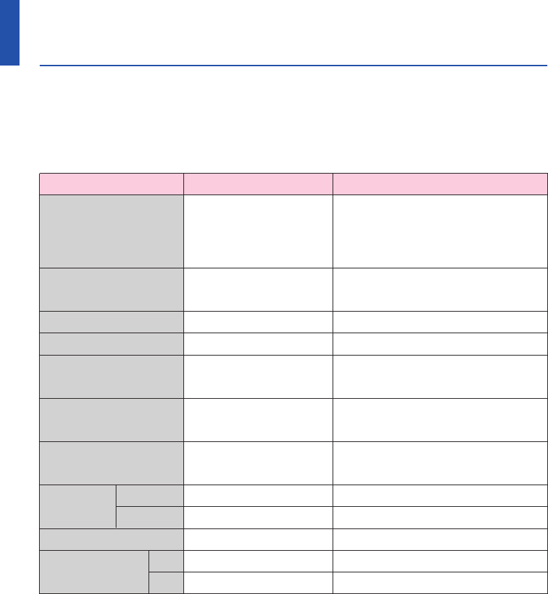
Name Model Comments
① Set Type RC-K3E-002-***S Product number for all sets.
Determined according to
combination of finger, shank
and direct output code.
② Sensor Head RC-K3E-002-***H Set number for ③+④+⑤+⑥+⑦.
Determined according to finger.
③ Sensor Unit RC-K3E-002HJ Sensor body only
④ Finger F-R40T-405 Standard finger (ruby ball Sφ4)
⑤1/2AA BT-001-001 Recommended dedicated
Lithium battery touch probe battery
⑥ Finger spanner S907 Tool for fastening and removing
finger
⑦ Finger wrench HEX-0.89 Tool for fastening and removing
finger
⑧ Shank BT30 H-BT30-001 Shank BT30
BT40 H-BT40-001 Shank BT40
⑨ Receiver RC-R02-001 Receiver
⑩ Output Cable 5m DC-R02-050 Cable 5m
10m DC-R02-100 Cable 10m
6.Parts List

23
24
www.metrol.co.jp
www.metrol.co.jp
NOTE
Name Model Comments
① Set Type RC-K3E-002-***S Product number for all sets.
Determined according to
combination of finger, shank
and direct output code.
② Sensor Head RC-K3E-002-***H Set number for ③+④+⑤+⑥+⑦.
Determined according to finger.
③ Sensor Unit RC-K3E-002HJ Sensor body only
④ Finger F-R40T-405 Standard finger (ruby ball Sφ4)
⑤1/2AA BT-001-001 Recommended dedicated
Lithium battery touch probe battery
⑥ Finger spanner S907 Tool for fastening and removing
finger
⑦ Finger wrench HEX-0.89 Tool for fastening and removing
finger
⑧ Shank BT30 H-BT30-001 Shank BT30
BT40 H-BT40-001 Shank BT40
⑨ Receiver RC-R02-001 Receiver
⑩ Output Cable 5m DC-R02-050 Cable 5m
10m DC-R02-100 Cable 10m
6.Parts List

RC-K3E
METROL CO., LTD.
Three-Dimensional
Touch Probes
Instruction Manual
METROL CO., LTD.
1-100 Takamatsu-cho Tachikawa, Tokyo 190-0011 JAPAN
Tel: +81 50 5558 7366 / Fax: +81 42 528 1442
E-mail: touchsensor@metrol.co.jp
TOKYO JAPAN
The specifications and descriptions are subject to change without notice due to improvements in products.
GM-RCK3E-E-K003