Metrum Technologies UTILIWISEECM under-the-cover IP-based wireless communications device User Manual
Metrum Technologies, LLC under-the-cover IP-based wireless communications device
UserManual.wiki
>
Metrum Technologies
>
UTILIWISEECM User Manual
User Manual
Navigation menu
Upload a User Manual
Namespaces
Wiki Guide
HTML
PDF
Info
Views
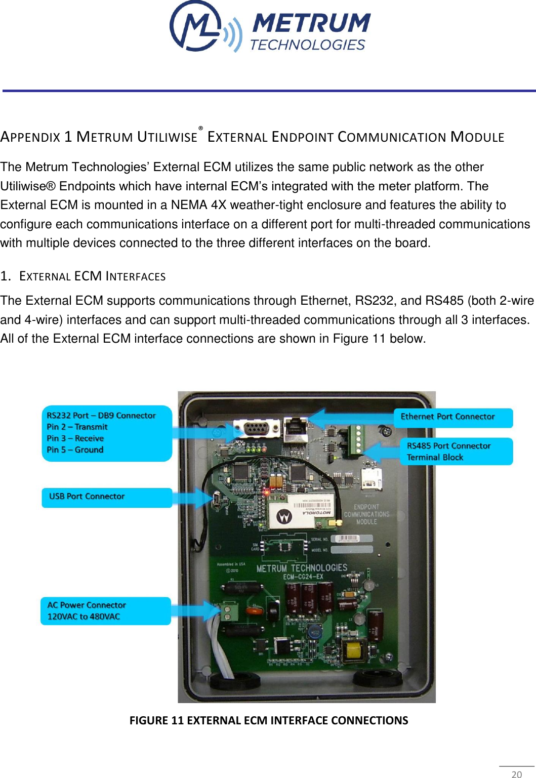
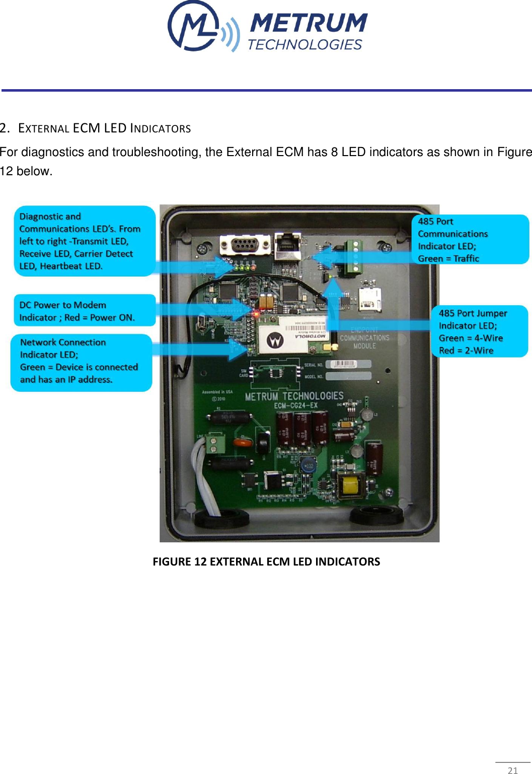
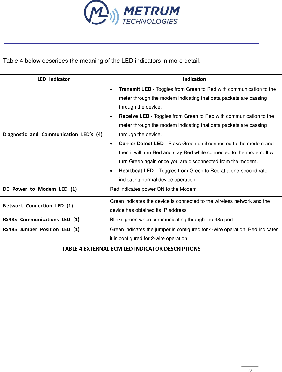
User Manual
Discussion / Help
Navigation