Metrum Technologies UTILIWISEECM under-the-cover IP-based wireless communications device User Manual
Metrum Technologies, LLC under-the-cover IP-based wireless communications device
User Manual

Web: www.metrum.us
Office: 254-752-7300
Confidential The contents of this manual are confidential and constitute the exclusive property of METRUM TECHNOLOGIES, LLC. This manual and its contents
may not be made public in any manner, distributed or loaned to others or reproduced or copied either in whole or part without prior written consent from
Metrum.
© 2011 METRUM
METRUM UTILIWISE® ENDPOINT COMMUNICATION MODULE
USER’S MANUAL

i
Notice
© 2011 Metrum Technologies, LLC
All rights reserved.
No part of this document may be reproduced or transmitted in any form or by any means,
electronic or mechanical, for any purpose without the express written permission of Metrum
Technologies, LLC.
Metrum Technologies, LLC makes no representations or warranties with respect to the contents
or use of this manual and specifically disclaims any warranties, express or implied, of
merchantability or fitness for any specific purpose. Further, Metrum Technologies, LLC reserves
the right to revise this publication and to make any modifications to its content, at any time,
without obligation to notify any party, person, or entity of such revisions or changes.
Product specifications cited are those in effect at time of publication. Metrum Technologies, LLC
shall not be liable for errors contained herein or for incidental or consequential damages in
connection with the furnishing, performance, or use of this material.
UtiliWise®, Configurator and ECM are trademarks and/or registered trademarks of Metrum Technologies, LLC.
MOTOROLA and the Stylized M Logo are registered in the US Patent & Trademark Office.
All other product and company names mentioned herein may be the trademarks and/or registered trademarks of
their respective owners.
For further information, contact:
Metrum Technologies
315 S. University Parks Dr.
Waco, TX 76701
Office: 254-752-7300
Fax: 254-752-7302
Email: info@metrum.us
Web: www.metrum.us

ii
Document History
Title: Metrum UtiliWise® Endpoint Communication Module User’s Manual
Revision Level
Date Issued
Description
Original
07/2011
Initial Release
Version 2.0
12/7/2011
Major update
Version 3.0
12/21/2011
Modified FCC Compliance Section

iii
CONTENTS
1. Metrum UtiliWise® Endpoint Overview ............................................... 1
2. Utiliwise® Endpoint Configuration and Communication ....................... 4
2.1. Utiliwise® Endpoint Configuration Procedure ................................................................................................................................ 4
2.1.1. Connect USB cable to the Utiliwise® Endpoint ................................................................................................................................ 4
2.1.2. Install Metrum Configurator Software ................................................................................................................................................. 6
2.1.3. Use the Metrum Configurator to verify Endpoint Settings .......................................................................................................... 7
2.1.4. ECM Configuration Features for the Verizon Network .............................................................................................................. 10
2.2. IP Communication Procedure for Metrum Wireless ECM’s ..................................................................................................... 11
2.2.1. Cisco AnyConnect ........................................................................................................................................................................................ 11
2.2.2. Site-to-site VPN tunnel.............................................................................................................................................................................. 12
2.3. Initial Inspection, Power-Up, and Troubleshooting Procedures ............................................................................................ 14
Appendix 1 Metrum Utiliwise® External Endpoint Communication Module 16
1. External ECM Interfaces ................................................................................................................................................................................ 16
2. External ECM LED Indicators ...................................................................................................................................................................... 17

iv
FCC Compliance
This equipment has been tested and found to comply with the limits for a Class B digital device,
pursuant to part 15 of the FCC Rules. These limits are designed to provide reasonable
protection against harmful interference in a residential installation. This equipment generates,
uses, and can radiate radio frequency energy and, if not installed and used in accordance with
the instructions, may cause harmful interference to radio communications. However, there is no
guarantee that interference will not occur in a particular installation. If this equipment does
cause harmful interference consult Metrum Support for help.

v
Safety Information
The following safety precautions must be observed during all phases of operation, service, and
repair of this device. Failure to comply with these precautions or with specific warnings
elsewhere in this manual violates safety standards of design, manufacture, and the intended
use of the metering instrument. Metrum Technologies, LLC assumes no liability for the
customer's failure to comply with these requirements.
• Warning: Any work on, or near, energized meters, meter sockets, or other metering
equipment can present a danger of electrical shock. All work on this product should be
performed only by qualified electricians and metering specialists in accordance with local
utility safety practices, utility requirements and procedures outlined in Chapter 14 of The
Handbook for Electricity Metering (10th edition). The information contained within this
manual is intended to be an aid to qualified metering personnel. It is not intended to replace
the extensive training necessary to handle metering equipment in a safe manner.
• Use care when servicing with the power on.
• Be aware that dangerous voltages exist at several points within the meter when this
product is installed on a meter base.
• Disconnect power before meter disassembly, soldering, or replacing components.
The meter is connected directly to line potential. Due to the possibility of the potential lines being
reversed, points accessible with the cover off may be at line voltage.
LINE POTENTIAL IS PRESENT ON THE INCOMING CONNECTORS ON THE METRUM
UtiliWise® COMMUNICATIONS BOARD AND ON THE MEASUREMENT BOARD
INCLUDING THE BATTERY CONNECTOR.
Consult the meter Instruction/Technical Manual for meter specific information.

1
1. METRUM UTILIWISE® ENDPOINT OVERVIEW
Metrum Utiliwise® Endpoints are comprised of a Metrum Endpoint Communications Module
(ECM) integrated with one of the supported electric meter platforms shown in Figure 1 below.
Metrum also has an external ECM also shown in Figure 1 which enables wireless
communications with distribution assets such as breakers, regulators, capacitor banks, or any
device equipped with communication outputs. A detailed description of Metrum’s External
ECM is in Appendix 1.
Elster A3 Itron Sentinel Landis+Gyr S4
Landis+Gyr Focus Itron Centron II Metrum External ECM
FIGURE 1 METRUM SUPPORTED ECM METER PLATFORMS
Figure 1c

2
The ECM enables two-way, wireless communications between the meter and the utility
interface over the public network carriers such as Sprint, Verizon, AT&T, or Metrum Wireless
which is an aggregation of several public carriers. The ECM’s are Internet Protocol (IP)
devices using pass-through communications enabling Head-End software like MV-90 to
retrieve and communicate across the public networks any registers, billing determinants or the
contents of any ANSI table supported by the meter. Reading frequency and data retrieved is
completely configurable and supports up to 4 sec interval communications between the Head-
End and Endpoint. All ECM’s can operate in multiple modes and support inbound and
outbound TCP/IP and UDP communications, real-time communications, remote mode
configuration, firmware upgrades, dynamic carrier selection, signal quality monitoring, remote
diagnostics, self-registration, and pass-through communications. In addition, the ECM’s
feature a solid state, auto-ranging power supply which is independent of the meter power
supply and can be easily retrofitted with multiple antenna options.
For communication with various devices in a ZigBee Smart Energy Home Area Network
(HAN), the ECM’s also have an optional integrated 100mW ZigBee module that is Smart
Energy 1.0 certified and Smart Energy 2.0 ready. The ZigBee module firmware can be
upgraded Over The Air (OTA) enabling easy migration from SE 1.0 to SE 2.0.
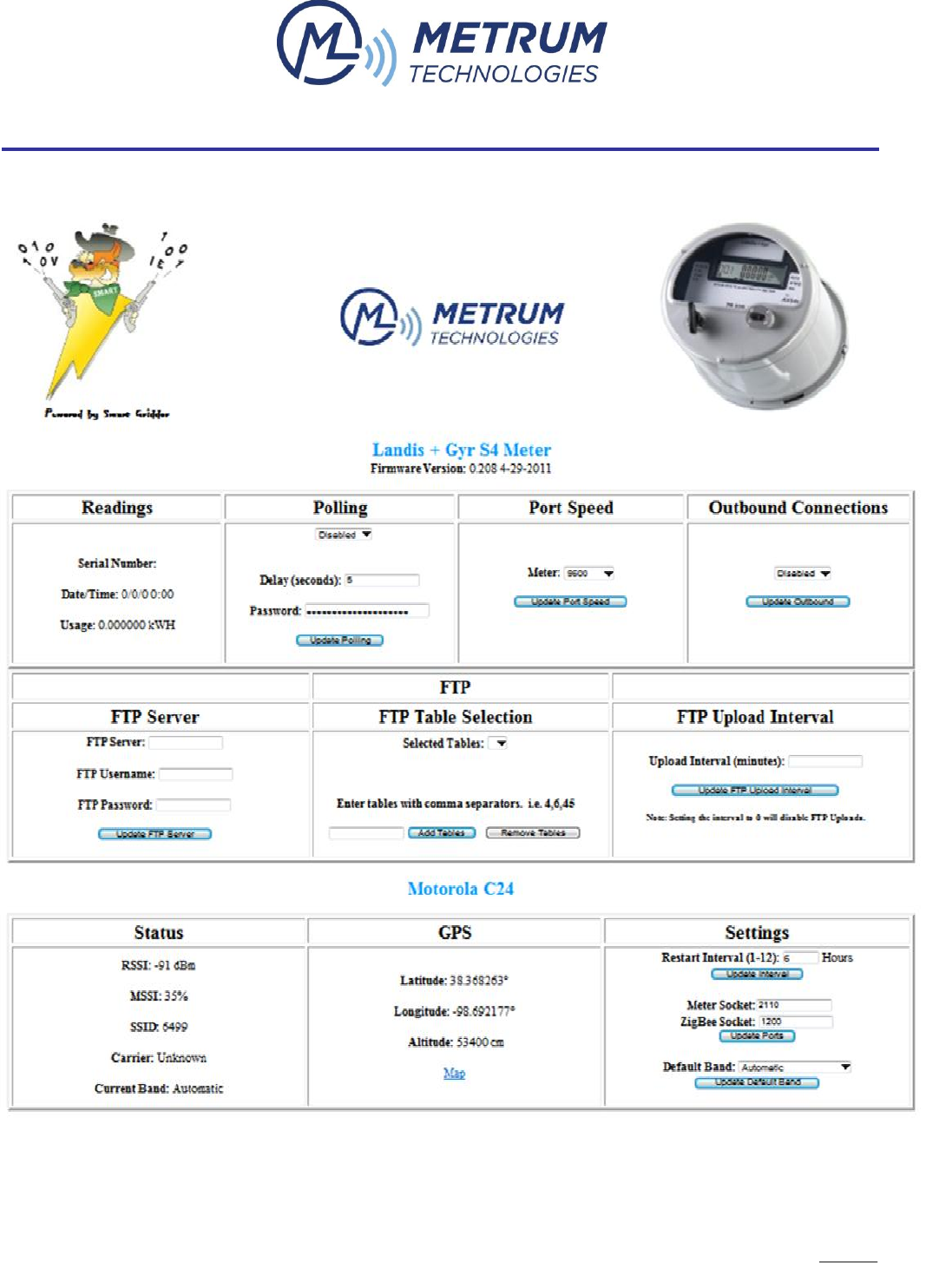
Each Utiliwise® Endpoint, as a standard feature, hosts a webpage for diagnostics and control
similar to the one shown in


5
FIGURE 2 UTILIWISE® ENDPOINT WEBPAGE

6
2. UTILIWISE® ENDPOINT CONFIGURATION AND COMMUNICATION
Although the Utiliwise® Endpoints are usually shipped with activated modems, customers should
always perform a “Settings” check before field installation which is also the first step in
troubleshooting a Utiliwise® Endpoint.
2.1. UTILIWISE® ENDPOINT CONFIGURATION PROCEDURE
2.1.1. CONNECT USB CABLE TO THE UTILIWISE® ENDPOINT
The Metrum USB driver package is included on the Metrum CD with your order and is also
available for download from the Metrum website at www.metrum.us/login where you will need
your login credentials. The first step is to power-up the UtiliWise® Endpoint and connect the
supplied USB cable which is a standard USB Mini cable. Connect the USB A end of the
supplied cable to a USB port on your computer, and connect the USB Mini end of the cable to
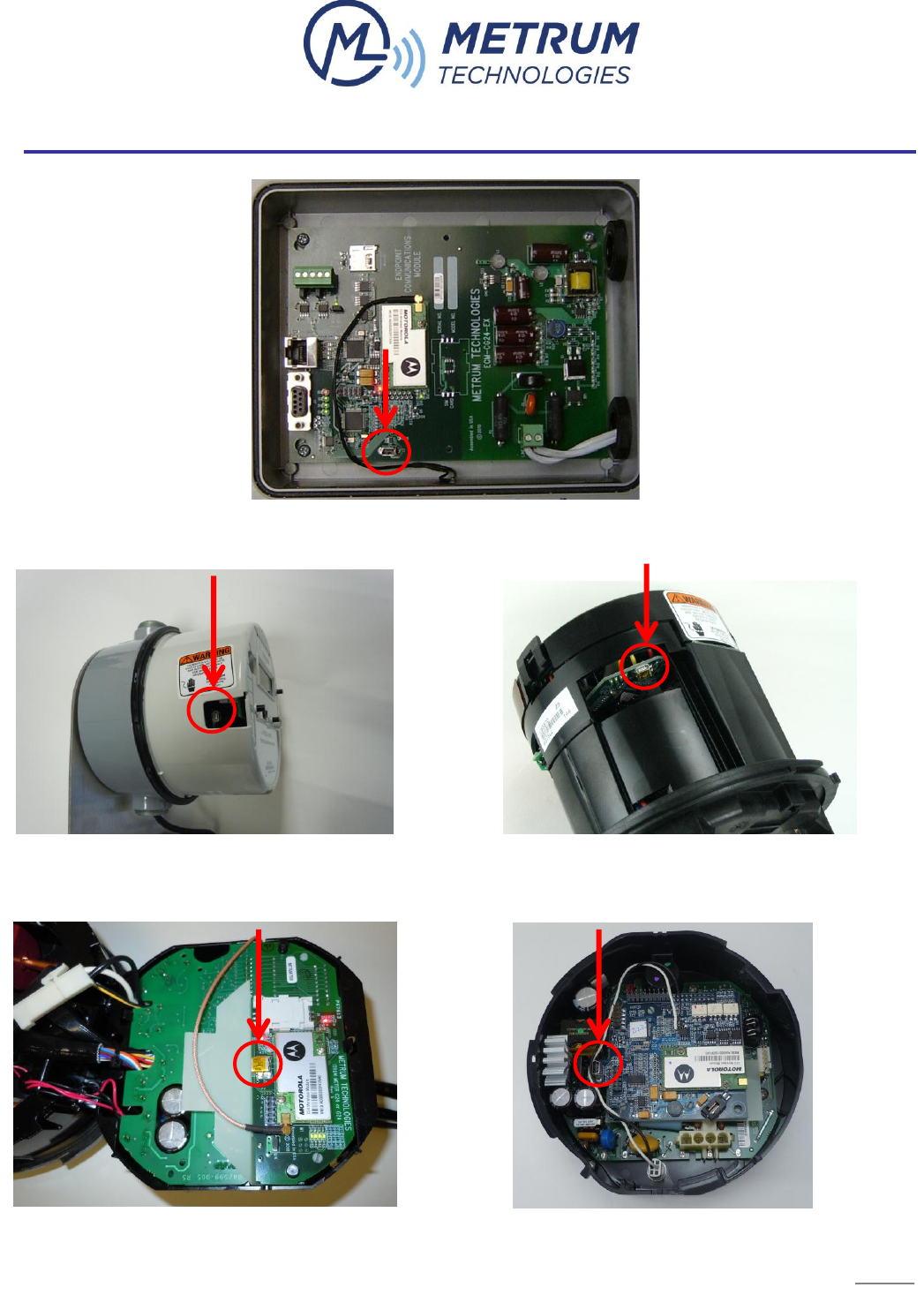
the exposed mini connector on the UtiliWise® Endpoint. The locations of the USB connector
under the cover of the UtiliWise® Endpoint meter platforms are shown in Figures 3-7 below.
7
FIGURE 3 EXTERNAL ECM USB CONNECTOR
FIGURE 4 FOCUS ECM USB CONNECTOR FIGURE 5 S4 ECM USB CONNECTOR
FIGURE 6 SENTINEL ECM USB CONNECTOR FIGURE 7 A3 ECM USB CONNECTOR

8
When the Windows® new hardware wizard prompts for driver installation, browse to the Metrum
USB folder where the driver is located. Once installed, follow the steps below.
1. Open Device Manager.
2. Open the Properties window for the Metrum USB.
3. Verify the COM port number for use in the Metrum Configurator application described in
the next section
4. Verify the baud rate is set to 115200.
5. Click "OK" to close the Properties dialog window and exit Device Manager.
Once the USB cable is connected, apply power to the meter if not already powered up and
ensure the LED’s on the UtiliWise® ECM are lit before continuing. On each of the Metrum
Utiliwise® ECM’s, there are 4 LED’s placed near each other and labeled D10, D11, D12, and
D13. These LED’s indicate the state of the ECM and are described in the table below.
LED Designator
Description
Normal State
Activity
D10
Power Indicator
Green blinking Red
D11
Carrier Detect
Green
Solid Red during session
D12
Receive
Green
Blinking Red
D13
Transmit
Green
Blinking Red
All four LEDs above blink Red simultaneously once the ECM acquires its mobile IP and then every
10 seconds thereafter verifying it has not lost connectivity.
2.1.2. INSTALL METRUM CONFIGURATOR SOFTWARE
The Metrum Configurator is the software used to perform a “Settings” check before field
installation of the Utiliwise® Endpoint. It is compatible with Microsoft Windows® operating
systems 98SE and later. Follow the steps below to install Configurator on your PC.
1. Copy the Configurator folder from the supplied Metrum CD-ROM to the desired location
on your hard drive e.g. “C:\Program Files\Metrum”.
9
2. Open the folder you copied and right click on “Configurator.exe” and create a shortcut to
the program on your desktop.
3. Open the Configurator software by double-clicking, or single-clicking depend on your
Windows settings on the icon.
2.1.3. USE THE METRUM CONFIGURATOR TO VERIFY ENDPOINT SETTINGS
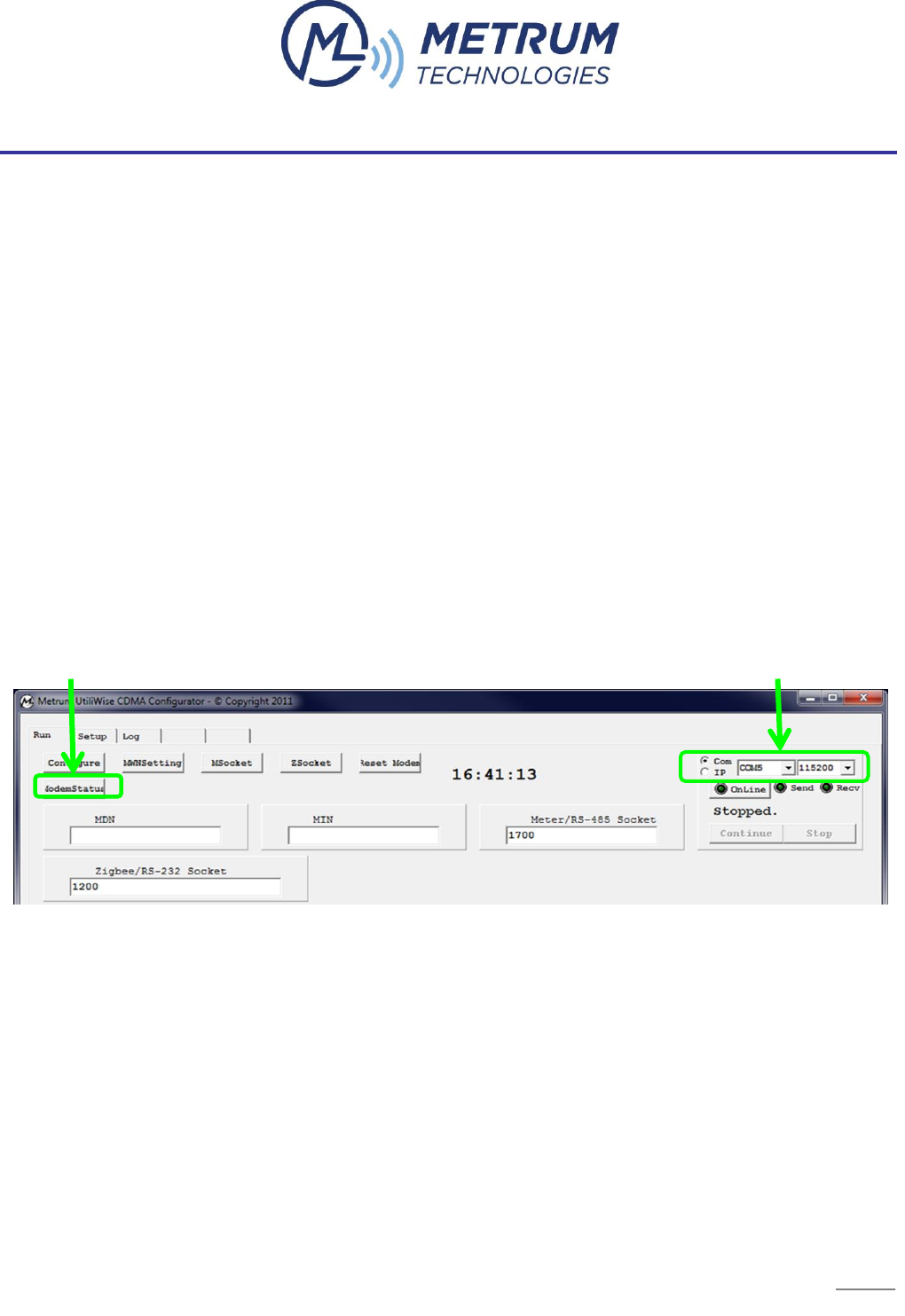
First, verify you have the correct COM port selected in the top right corner (e.g. COM1, COM2,
etc.); the default is set to COM1. While the Utiliwise® Endpoint is connected via the USB cable
to the computer, click on the “ModemStatus” button as shown in Figure 8 below.
Note: The software will only work with the USB cable attached to the ECM. If an invalid COM
port is selected, you will receive a timeout error message. If you receive a timeout error, retry
the operation again. If you are still unsuccessful, cycle the power to the unit, reseat the cable
connector, and retry.
FIGURE 8 METRUM CONFIGURATOR SCREENSHOT

10
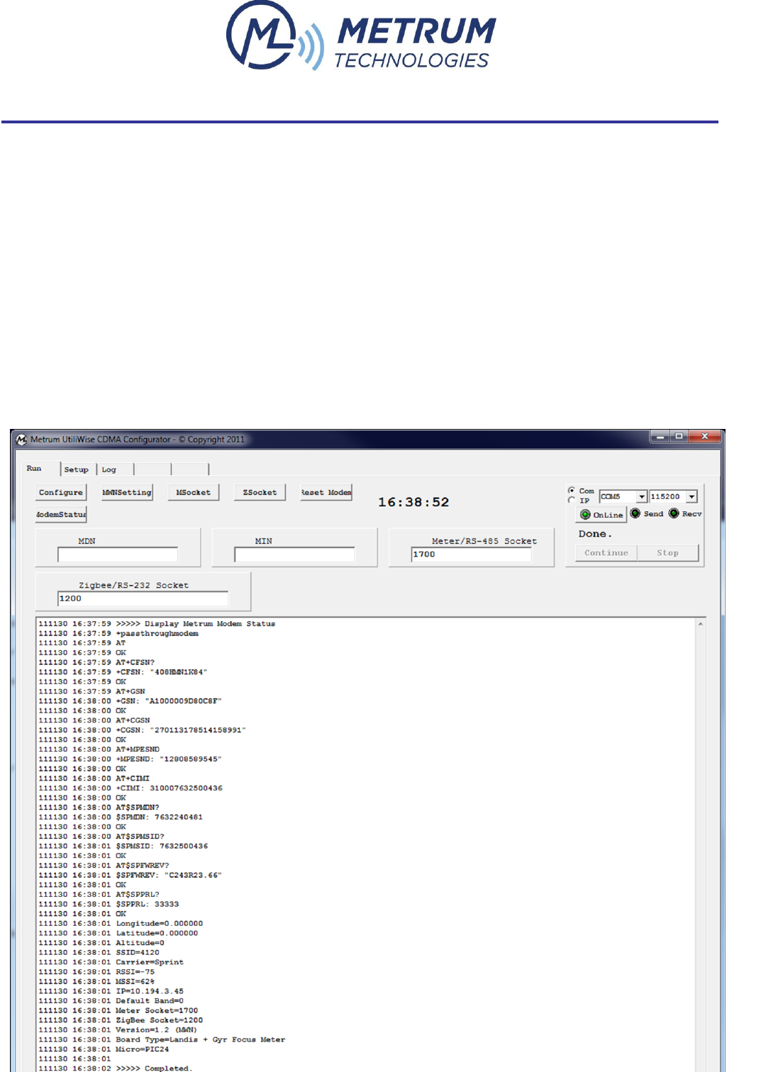
Once you click on the “ModemStatus” button highlighted above, the program will issue a series
of AT commands to determine the status of the modem. These commands are listed in Table 1
below.
Command
Example
Description
AT+WMIN?
+WMIN: 2145559999
Query Mobile Identification #
AT+WMDN?
+WMDN: 2145551234
Query Mobile Dial # (Phone #)
AT+CSQ?
+CSQ: 24, 99
Query Received Signal Quality. <SQM>,<FER>
Returns the Signal Quality Measure <SQM> and the
Frame Error Rate <FER> as follows:
<SQM>: 0-31 – Signal Quality Measurement; 99 – SQM
is not known or is not detectable.
<FER>: 99 – FER is not known or is not detectable.
AT+RSP?
+RSP: VERIZON
Query Wireless Carrier programmed in modem
AT+GMR
+GMR: S/W VER: gduvz14 PRL VER: 4
Query software and PRL (Preferred Roaming List) version
AT+GSN
+GSN: 6C1BD859
Query Hexadecimal ESN
AT*LISTENPORT?
1700
Query IP PORT programmed in modem.
AT*LOCALIP?
*LOCALIP: 70.196.178.164
Query IP Address assigned to modem
NOTE: This should never change with a Static IP
address.
AT*LISTENMODE=n
LISTENMODE=0
Set modem’s IP listening mode On or Off - 0=Off 1=On
AT*LISTENCLOSE
Disables IP listen mode.
TABLE 1 AT COMMAND LISTING

12
FIGURE 9 METRUM CONFIGURATOR AT COMMAND LISTING
13
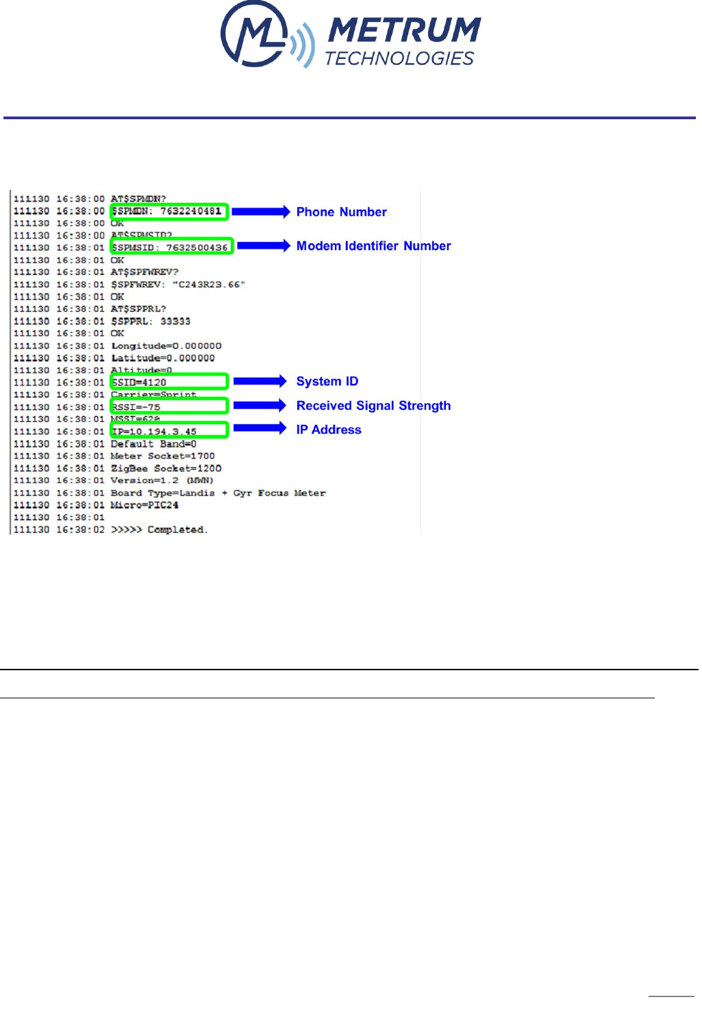
In this AT command listing, the settings to note are shown in
Figure 10 below.
FIGURE 10 METRUM CONFIGURATOR AT COMMAND SETTINGS OF INTEREST
If the ECM has a valid IP address, SSID, phone number, Modem Identifier Number, and an
RSSI greater than -110, the ECM is configured correctly and ready for IP communication.
Note: The default meter socket and ZigBee socket are 1700 and 1200 respectively, but these
can be changed in Configurator by changing the default values in the socket fields and clicking
on “Configure.”
2.1.4. ECM CONFIGURATION FEATURES FOR THE VERIZON NETWORK
Upon initial power up of a newly activated modem on the Verizon network, the ECM will
automatically acquire and program its MDN and MIN. This process can take up to 5 minutes to
complete during which time you will not be able to communicate remotely with the meter. Three

14
minutes after every subsequent power cycle and approximately every thirty days the ECM will
perform an over-the-air self-activation (OTA) and PRL (Preferred Roaming List) update.
2.2. IP COMMUNICATION PROCEDURE FOR METRUM WIRELESS ECM’S
Note: For ECM’s activated on the Verizon or AT&T networks, the IP communication procedure
should be coordinated with the carrier in terms of VPN access, etc.
For ECM’s activated on the Metrum Wireless Network, there are 2 ways to establish IP
communication with the Utiliwise® Endpoint using a VPN connection depending on the way the
head-end meter-reading software is setup.
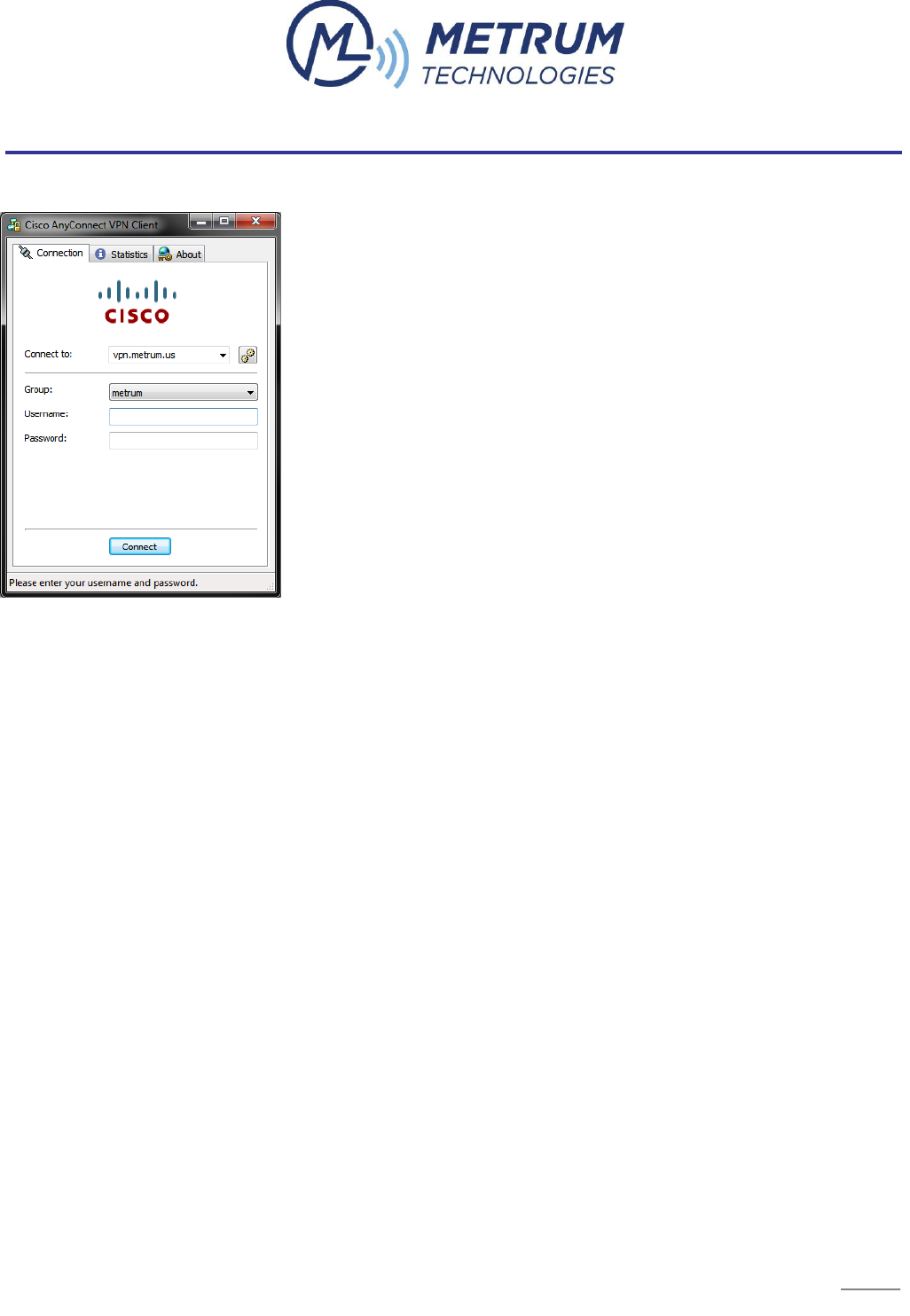
2.2.1. CISCO ANYCONNECT
Using the Cisco AnyConnect VPN client is the preferred VPN connection method for customers
reading Utiliwise® Endpoints over the Metrum Wireless Network (MWN) from a single host or
remote location with meter reading software. All Metrum Wireless Network (MWN) customers
that use the Cisco AnyConnect VPN client has an access control list (ACL) applied to their user
credentials which allow access only to customers assigned Metrum Wireless IP addresses with
all others denied.
This is not recommended for customers using automated server side meter reading software
systems or customers that have multiple hosts with metering software on their local area
network (LAN).
15
Cisco AnyConnect is compatible with the following Operating Systems.
Windows XP SP2 and SP3
Windows Vista (32-bit and 64-bit) SP2 or Vista Service Pack 1 with KB952876
Windows 7 (32-bit and 64-bit)
Red Hat Enterprise Linux 5 Desktop
Ubuntu 9.x
Mac OS X 10.5, and Mac OS X 10.6, 10.6.1, 10.6.2 (32-bit and 64-bit)
2.2.2. SITE-TO-SITE VPN TUNNEL
A site-to-site VPN tunnel is the preferred hardware VPN connection for customers reading
Utiliwise® Endpoints over the Metrum Wireless Network (MWN) that have automated server
side meter reading software systems or that have multiple hosts with metering software on
their local area network (LAN). All Metrum Wireless Network (MWN) customers that have a site-
to-site VPN tunnel with Metrum has a group policy in place with an access control list (ACL)
applied to it. This allows access only to customers assigned Metrum Wireless IP addresses with
all others denied.
Compatible hardware includes the following:

16
Cisco ASA 5500 Series Adaptive Security Appliances and Cisco routers
SonicWall security appliances
Check Point security appliances
For Metrum Wireless Network (MWN) customers wanting to setup a site-to-site VPN tunnel
between MWN and their company, please complete Table 2 below with your IT department and
send it back to the Metrum Wireless Network Administrator.

17
TABLE 2 SITE-TO-SITE VPN TUNNEL INFORMATION
Please enter the details below. This information will be used to configure the Site-to-Site VPN tunnel.
MWN - VPN Device Make/Model
Cisco ASA 5510
MWN - VPN Device OS/Software Version
Software Version 8.0(4)
MWN - VPN Peer IP Address
66.112.39.18
MWN - Network Range/s
10.194.0.0/16
10.192.0.0/16 (Only needed for customers with MWN IP
addresses assigned before 7/15/2011).
Remote - VPN Device Make/Model
?
Remote - VPN Device OS/Software Version
?
Remote - VPN Peer IP Address
?
Remote - Network Range/s
?
Pre-Shared Secret (IPsec) (Min 20 Characters)
Shared over phone or sent in email w/o a subject
IKE Phase 1 Encryption Algorithm (AES-256/3DES/DES)
AES-256
IKE Phase 1 Data Integrity Method (SHA1/MD5)
SHA
IKE Phase 1 Timeout Period (Default: 86400 Seconds)
Default
IKE Phase 1 Diffie-Hellman Group (Group1/Group2/Group3)
Group2
IKE Phase 2 Encryption Algorithm (AES-256/AES-128/3DES/DES)
AES-256
IKE Phase 2 Data Integrity Method (SHA1/MD5)
SHA
IKE Phase 2 Timeout Period (Default: 28800 Seconds)
Default
IKE Phase 2 PFS Required (YES/NO)
NO
PFS Diffie-Hellman Group (Group1/Group2/Group3; If PFS not
required leave blank)
NO
Additional Notes/Comments:
Ports/protocols to allow:
tcp/80
tcp/1200
tcp/1300
tcp/1700
tcp/ customer specific port (optional)
ICMP

18
2.3. INITIAL INSPECTION, POWER-UP, AND TROUBLESHOOTING PROCEDURES
In addition to the “Settings” check of the Utiliwise® Endpoint with the Metrum Configurator
described in this document, we recommend the following visual inspection and initial power-up
procedure before field installation.
2.3.1. Visual Inspection
2.3.1.1. Without completely disassembling the unit; inspect the unit for apparent
damage.
2.3.1.2. Verify all wire connectors are still connected.
2.3.1.3. If present, verify the KYZ or other option boards are in place and
connected.
2.3.1.4. Verify the ECM boards components soldered properly.
2.3.1.5. If visible, verify that the MEID of the ECM modem matches nameplate
label.
2.3.2. Initial Power up
2.3.2.1. Verify the meter LCD and ECM board LED’s are lit.
2.3.2.2. Read the meter optically to verify remote options are set correctly.
2.3.2.3. Power down the unit.
If there are any issues found during inspection, power-up, the “settings” check in Configurator,
or field operation, use the Endpoint Troubleshooting Guide in Table 3 below to diagnose/resolve
the problem.
If you are still unable to resolve the problem, send a description and any relevant
documentation like a screenshot of the AT command listing in Configurator to
support@metrum.us or contact Metrum directly at 254-752-7300.

19
Problem
Possible Causes
What to Check
No LED’s
No power to the Endpoint
No/corrupt ECM firmware
Ensure the Endpoint has power. There
should be at least 120V AC at the input
power leads of the ECM
Ensure the ECM has a firmware label on
the board
No / Incorrect ECM
Response in Configurator
No power to the Endpoint
No/poor USB connection to the
Endpoint
No/poor ECM connections
No/corrupt firmware on the
ECM
Ensure the Endpoint has power. There
should be at least 120V AC at the input
power leads of the ECM
Check the USB connection between the
Endpoint and PC
Check the ECM connections with the meter
Ensure the ECM has a firmware label on
the board
Cannot Communicate
Remotely with ECM
Poor antenna connection
Low signal strength
Incorrect MDN and/or MIN
Incorrect IP address
No/corrupt ECM firmware
Check the antenna connection
In Configurator, check the following
o Signal strength
o MDN and MIN
o IP Address
o ECM Firmware
Verify account is provisioned correctly (e.g.
3G, static IP, etc.)
Try to Ping the IP address for a response
Try to access the ECM webpage by
browsing to the IP address associated with
the endpoint
TABLE 3 ENDPOINT TROUBLESHOOTING GUIDE
20
APPENDIX 1 METRUM UTILIWISE® EXTERNAL ENDPOINT COMMUNICATION MODULE
The Metrum Technologies’ External ECM utilizes the same public network as the other
Utiliwise® Endpoints which have internal ECM’s integrated with the meter platform. The
External ECM is mounted in a NEMA 4X weather-tight enclosure and features the ability to
configure each communications interface on a different port for multi-threaded communications
with multiple devices connected to the three different interfaces on the board.
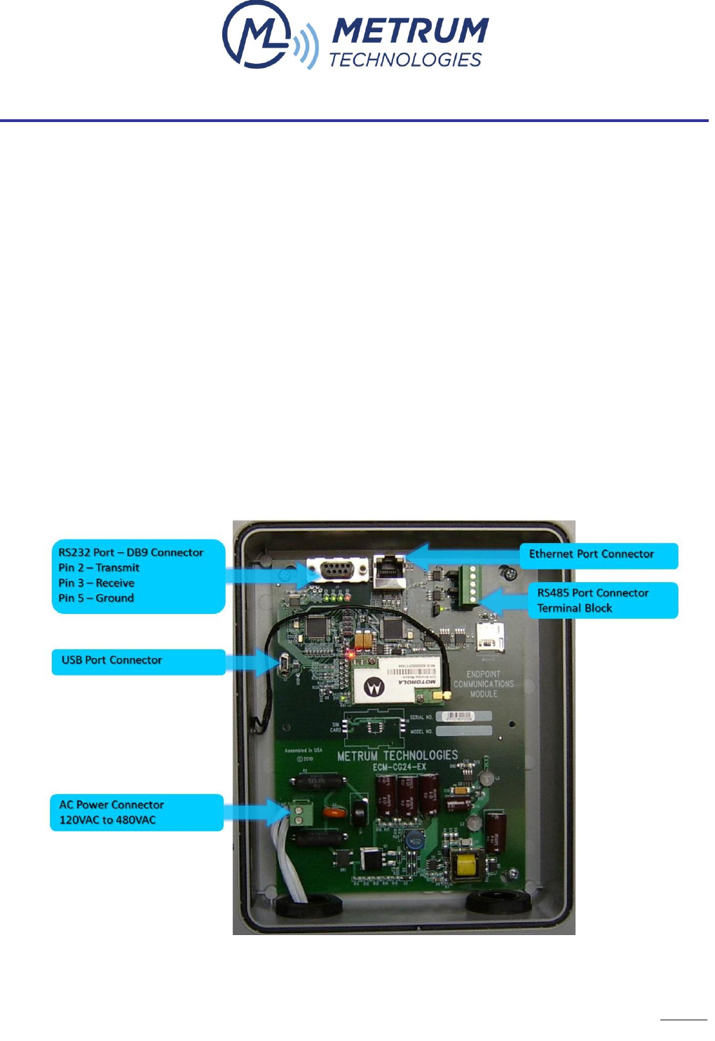
1. EXTERNAL ECM INTERFACES
The External ECM supports communications through Ethernet, RS232, and RS485 (both 2-wire
and 4-wire) interfaces and can support multi-threaded communications through all 3 interfaces.
All of the External ECM interface connections are shown in Figure 11 below.
FIGURE 11 EXTERNAL ECM INTERFACE CONNECTIONS

22
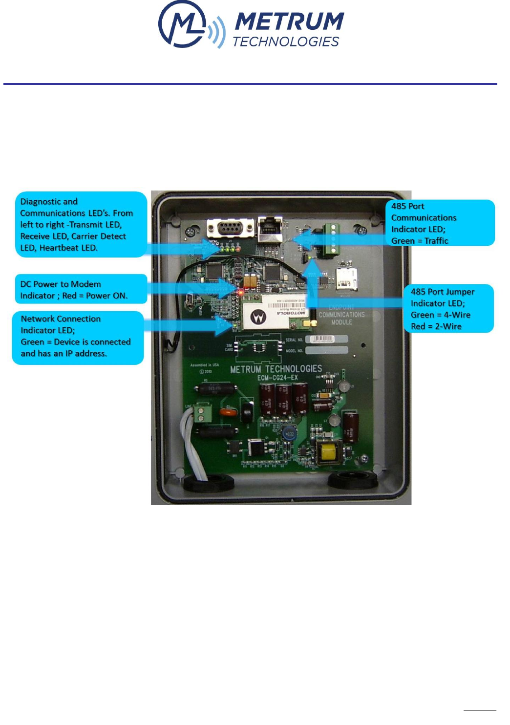
Table 4 below describes the meaning of the LED indicators in more detail.
LED Indicator
Indication
Diagnostic and Communication LED’s (4)
Transmit LED - Toggles from Green to Red with communication to the
meter through the modem indicating that data packets are passing
through the device.
Receive LED - Toggles from Green to Red with communication to the
meter through the modem indicating that data packets are passing
through the device.
Carrier Detect LED - Stays Green until connected to the modem and
then it will turn Red and stay Red while connected to the modem. It will
turn Green again once you are disconnected from the modem.
Heartbeat LED – Toggles from Green to Red at a one-second rate
indicating normal device operation.
DC Power to Modem LED (1)
Red indicates power ON to the Modem
Network Connection LED (1)
Green indicates the device is connected to the wireless network and the
device has obtained its IP address
RS485 Communications LED (1)
Blinks green when communicating through the 485 port
RS485 Jumper Position LED (1)
Green indicates the jumper is configured for 4-wire operation; Red indicates
it is configured for 2-wire operation
TABLE 4 EXTERNAL ECM LED INDICATOR DESCRIPTIONS