Micro Star MS3822 WLAN 802.11b/g/n 1T1R Slim Module User Manual Module
Micro Star International Co Ltd WLAN 802.11b/g/n 1T1R Slim Module Module
Contents
- 1. UserMan_I4L-MS3822_rev.
- 2. User Manual Host
- 3. User Manual Host Addendum
- 4. User Manual Module
User Manual Module

WLAN 802.11bgn 1T1R and BT2.1 EDR combo slim module
Application Note
Combo slim Module
Rev 1.0
Micro-Star International Co., Copyright 2009
Proprietary and Confidential
1
APPLICATION NOTE
MS-3822
WLAN 802.11b/g/n 1T1R Slim Module
WLAN 802.11bgn 1T1R and BT2.1 EDR combo slim module
Application Note
Combo slim Module
Rev 1.0
Micro-Star International Co., Copyright 2009
Proprietary and Confidential
2
Revision History
Revision Date Description Author/Revised by
1.0 2009/11/30 First version Benson
WLAN 802.11bgn 1T1R and BT2.1 EDR combo slim module
Application Note
Combo slim Module
Rev 1.0
Micro-Star International Co., Copyright 2009
Proprietary and Confidential
3
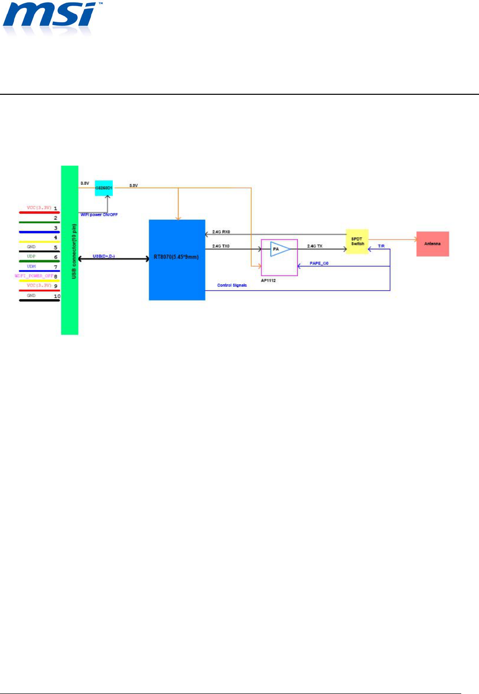
1. WLAN Module Block Diagram
Figure1: WLAN Module Block Diagram
WLAN 802.11bgn 1T1R and BT2.1 EDR combo slim module
Application Note
Combo slim Module
Rev 1.0
Micro-Star International Co., Copyright 2009
Proprietary and Confidential
4
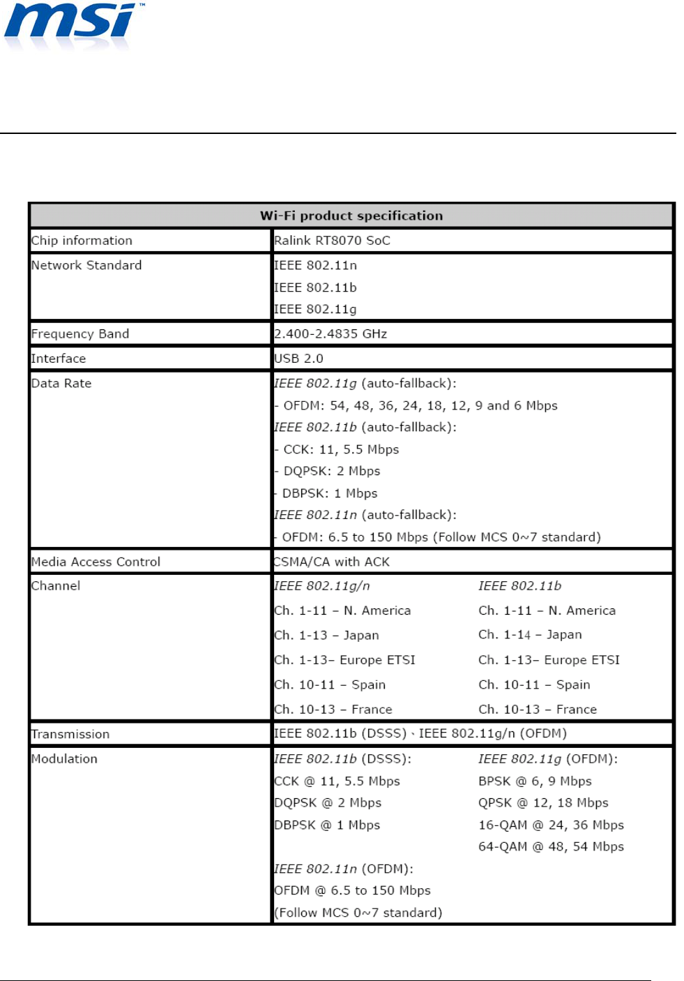
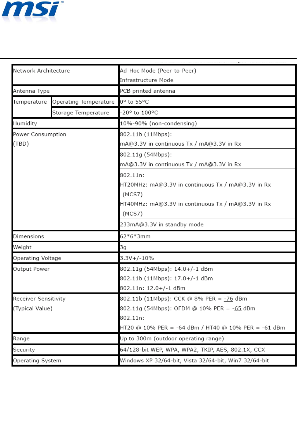
2. Product Specification
WLAN 802.11bgn 1T1R and BT2.1 EDR combo slim module
Application Note
Combo slim Module
Rev 1.0
Micro-Star International Co., Copyright 2009
Proprietary and Confidential
5
WLAN 802.11bgn 1T1R and BT2.1 EDR combo slim module
Application Note
Combo slim Module
Rev 1.0
Micro-Star International Co., Copyright 2009
Proprietary and Confidential
6
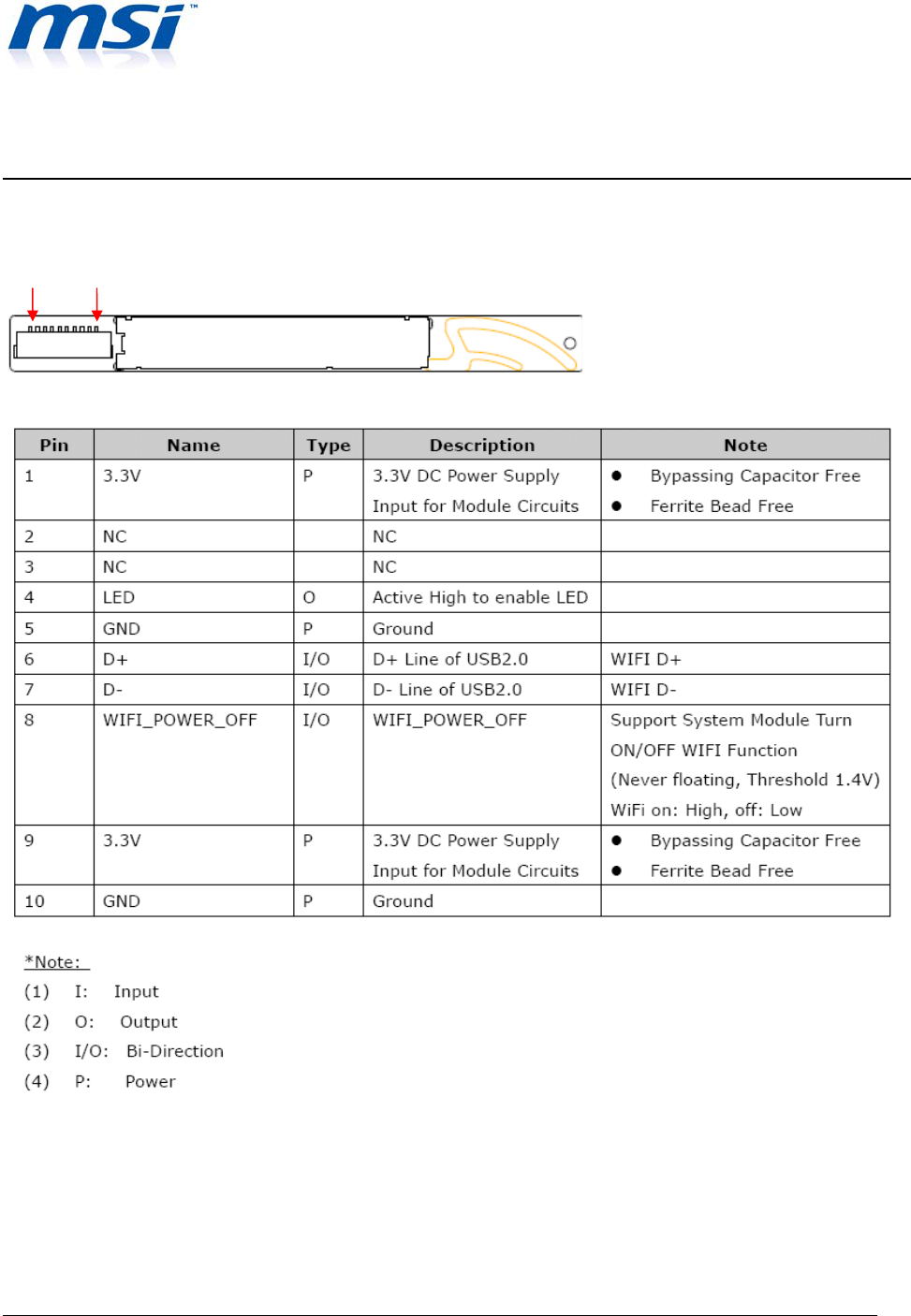
3. Module Pin Description
Table1: Combo Module Pin Description
Pin 1 Pin 10
WLAN 802.11bgn 1T1R and BT2.1 EDR combo slim module
Application Note
Combo slim Module
Rev 1.0
Micro-Star International Co., Copyright 2009
Proprietary and Confidential
7
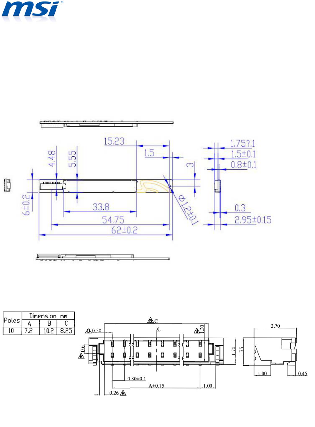
4. Mechanical Specifications
3.1 PCB Mechanical Drawing
Figure2: WLAN Module Dimension
3.2 Connector Mechanical Drawing
WLAN 802.11bgn 1T1R and BT2.1 EDR combo slim module
Application Note
Combo slim Module
Rev 1.0
Micro-Star International Co., Copyright 2009
Proprietary and Confidential
8
Figure3: Combo Module connector Dimension
4.3 Recommended Cable Length and Gauge
UL1571 32AWG HOOK UP WIRE OD=0.38mm, LENGTH=650mm (MAX.)
PS: This is the very minimum cable selection requirement. Performance could be more optimized if
cable length is shorter or premium cable is adopted.
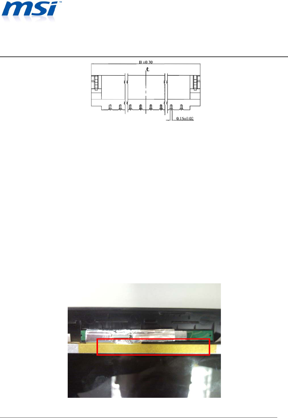
5. Recommended Assembly for WLAN Module
WLAN 802.11bgn 1T1R and BT2.1 EDR combo slim module
Application Note
Combo slim Module
Rev 1.0
Micro-Star International Co., Copyright 2009
Proprietary and Confidential
9
Applying insulating tape or other insulator and adhere it onto the module or LCD panel. This is to
prevent the module touching on the panel ground.
’
Giving at least 1-2mm gap or applying insulators (insulating tap) in between module & panel for
better isolation. (please note: This gap or isolation is only necessary when there is noise inducing
from the LCD panel)
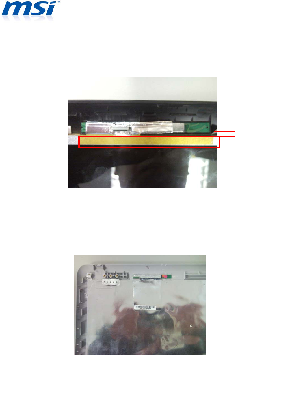
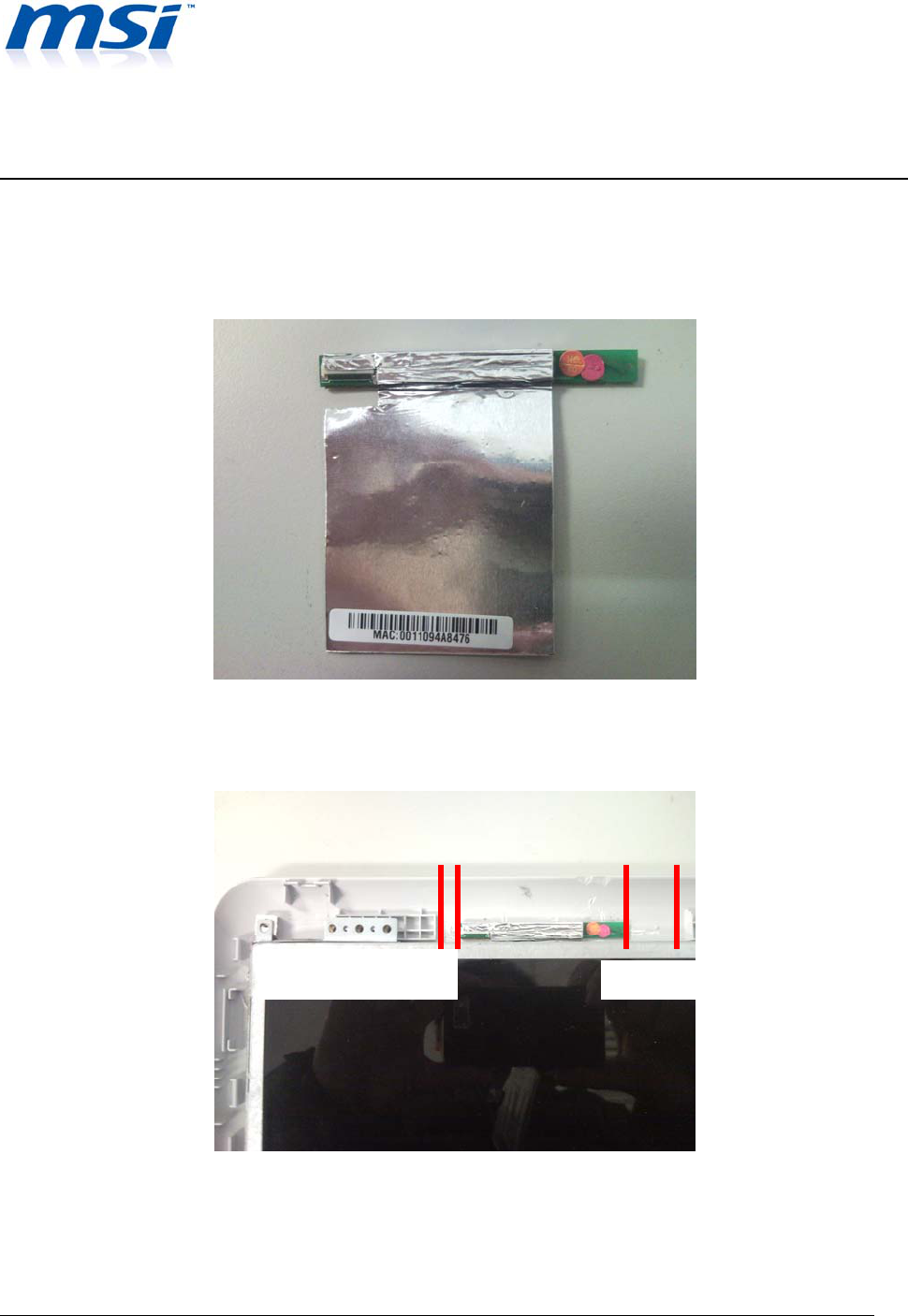
6. Solution for Thermal Reduction and Improving Antenna Gain
Adopting copper /aluminum foil or heat sink and then adhere it onto the top of combo module
shielding case. The bigger the foil/heat sink, the better the thermal conduction. Please note that
1~2mm gap
WLAN 802.11bgn 1T1R and BT2.1 EDR combo slim module
Application Note
Combo slim Module
Rev 1.0
Micro-Star International Co., Copyright 2009
Proprietary and Confidential
10
the size of foil/heat sink should just fit properly onto the shielding case. Foil/ heat sink size larger
than shielding area will impact the antenna performance. See below picture as a reference for
correct cutting size. Copper foil is highly recommended as it will enhance antenna performance.
7. Recommended Placement for Combo Module’s Antennas.
Leaving a gap between the combo module and NB housing ( the screw hole) for better antenna
performance.
0.5mm GAP ( BT) 10mm GAP
(
Wi-Fi
)
WLAN 802.11bgn 1T1R and BT2.1 EDR combo slim module
Application Note
Combo slim Module
Rev 1.0
Micro-Star International Co., Copyright 2009
Proprietary and Confidential
11
For Wi-Fi side, 10mm gap is recommended.
For Bluetooth side, 0.5mm gap is recommended.
Note: please avoid any metal parts to cover, touch or surround with antenna.
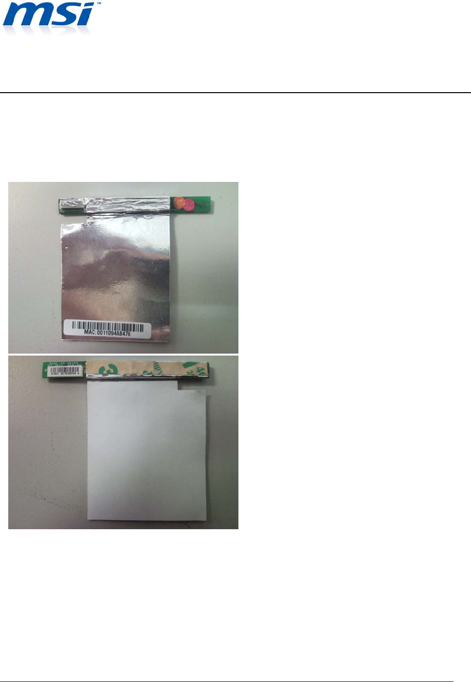
8. Recommended The Size Of Copper /Aluminum Foil
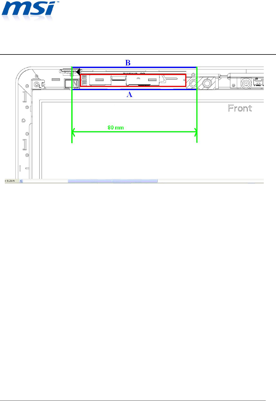
9. Recommended The EMI Coating Area
We suggest the area of EMI Coating must be within the length of Green line :100mm and the
width between blue line A and B (from the end of panel to end of A side). Don't Coating exceed
this area.
WLAN 802.11bgn 1T1R and BT2.1 EDR combo slim module
Application Note
Combo slim Module
Rev 1.0
Micro-Star International Co., Copyright 2009
Proprietary and Confidential
12