Micro Star MS6833A Mini PCI Card User Manual 8801
Micro Star International Co Ltd Mini PCI Card 8801
UserManual.wiki
>
Micro Star
>
MS6833A User Manual
Users Manual
Navigation menu
Upload a User Manual
Namespaces
Wiki Guide
HTML
PDF
Info
Views
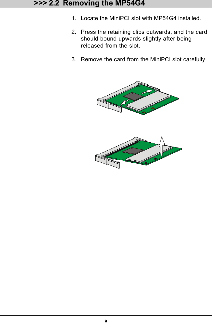
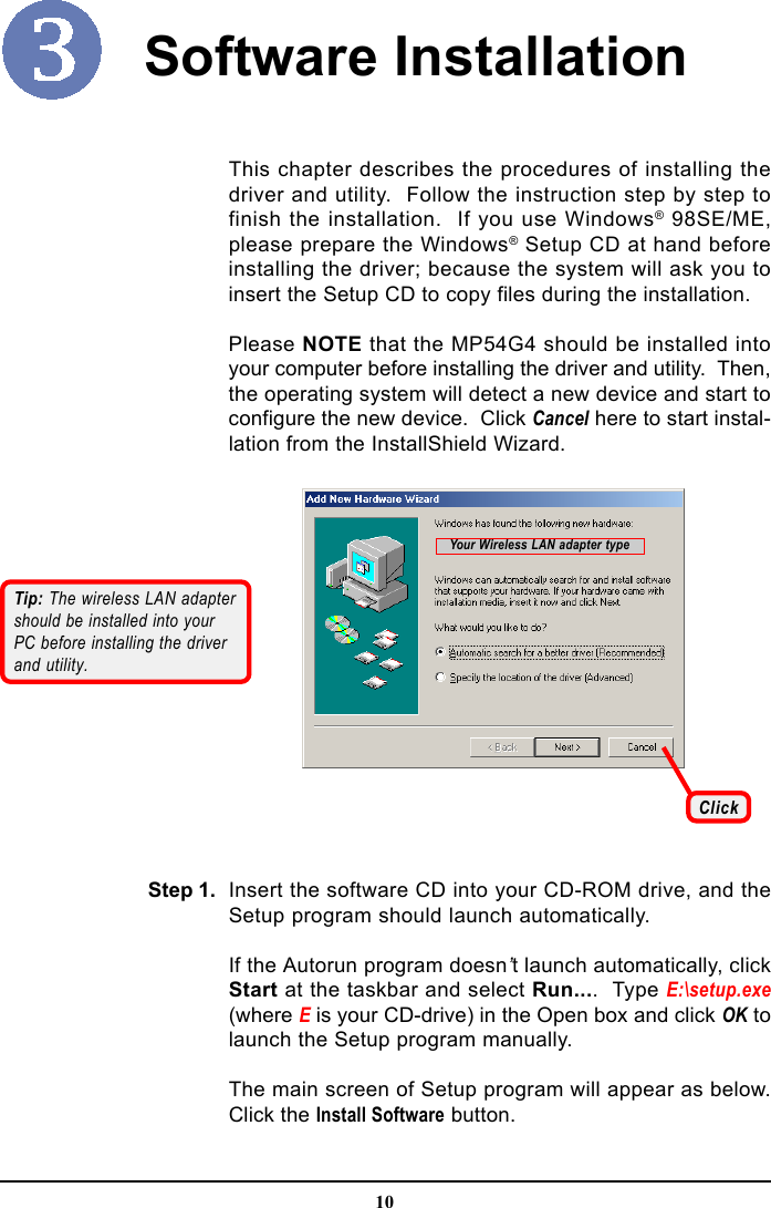
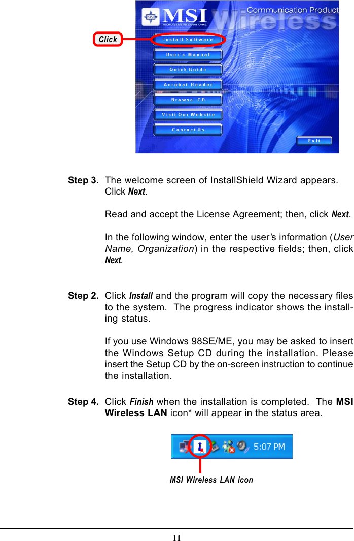
User Manual
Discussion / Help
Navigation