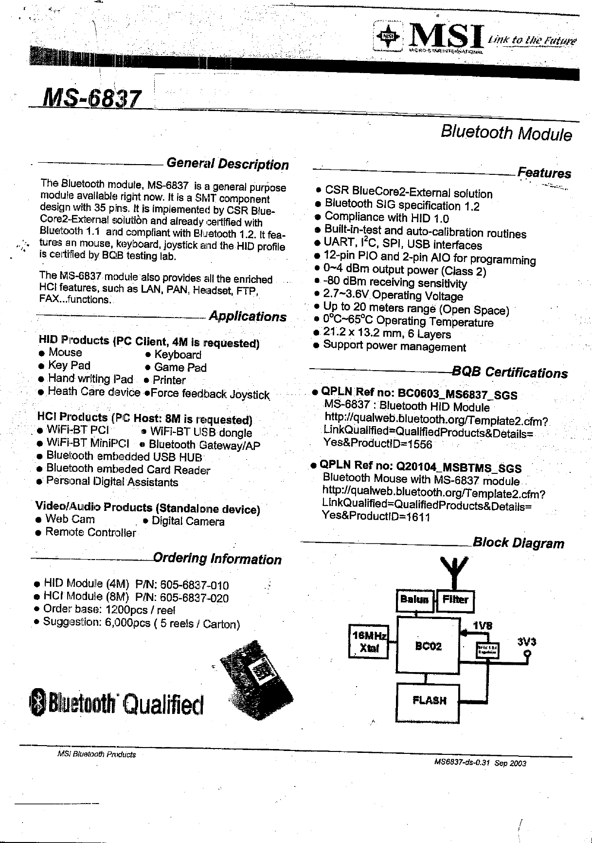
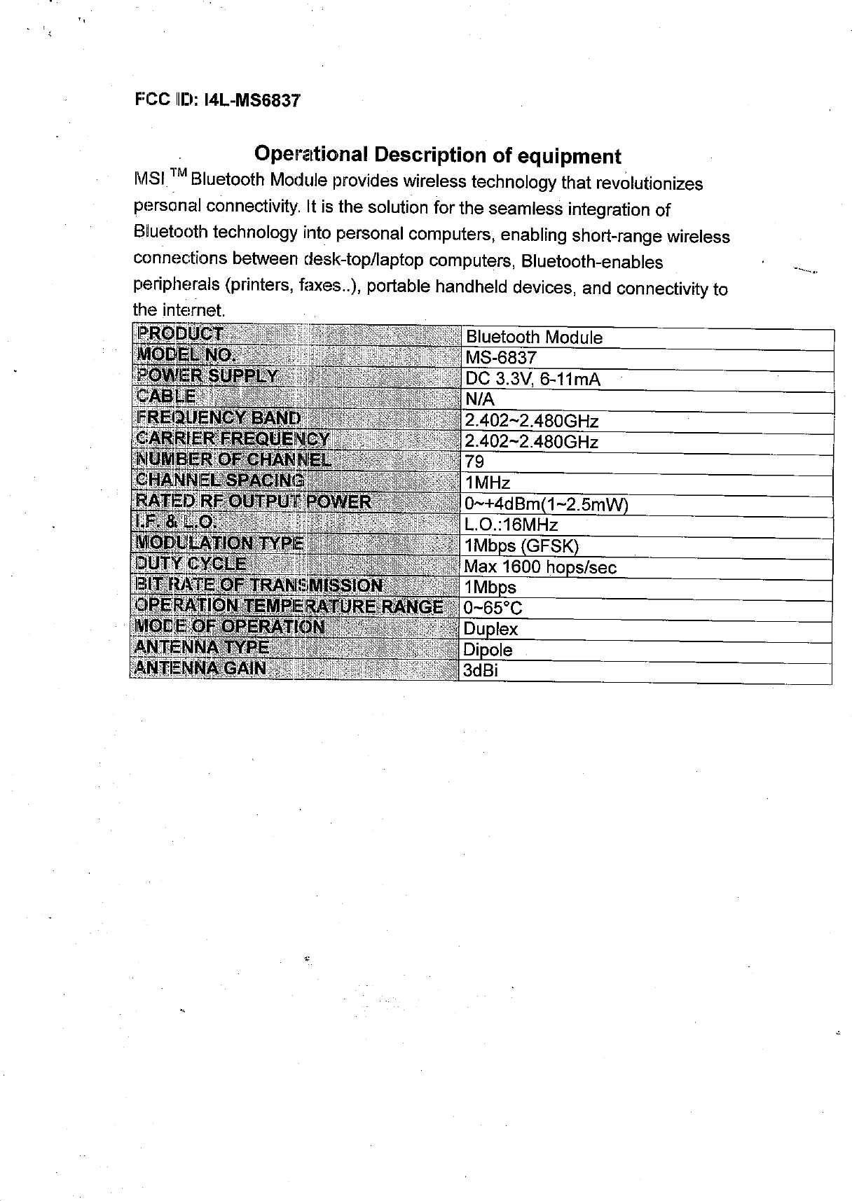
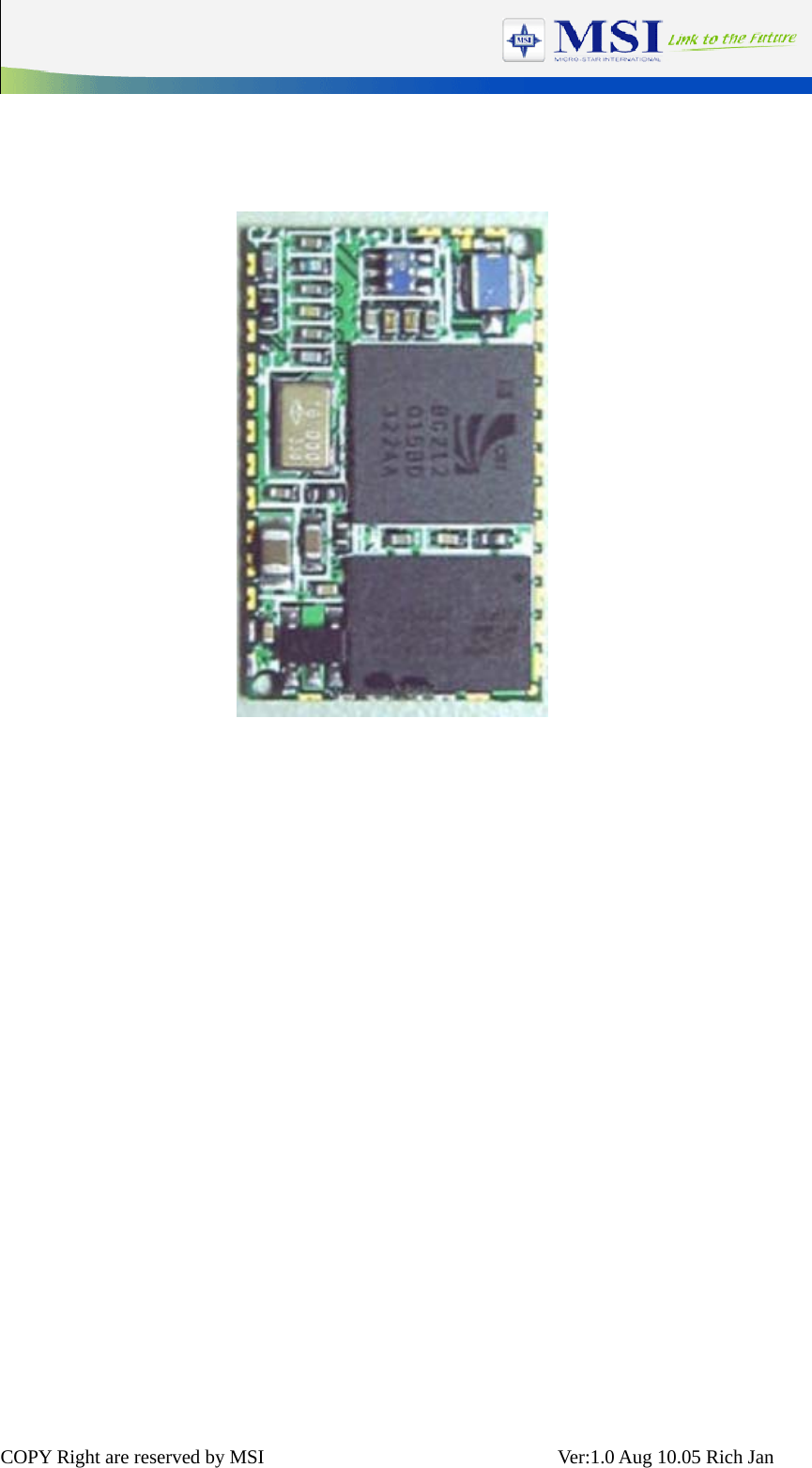
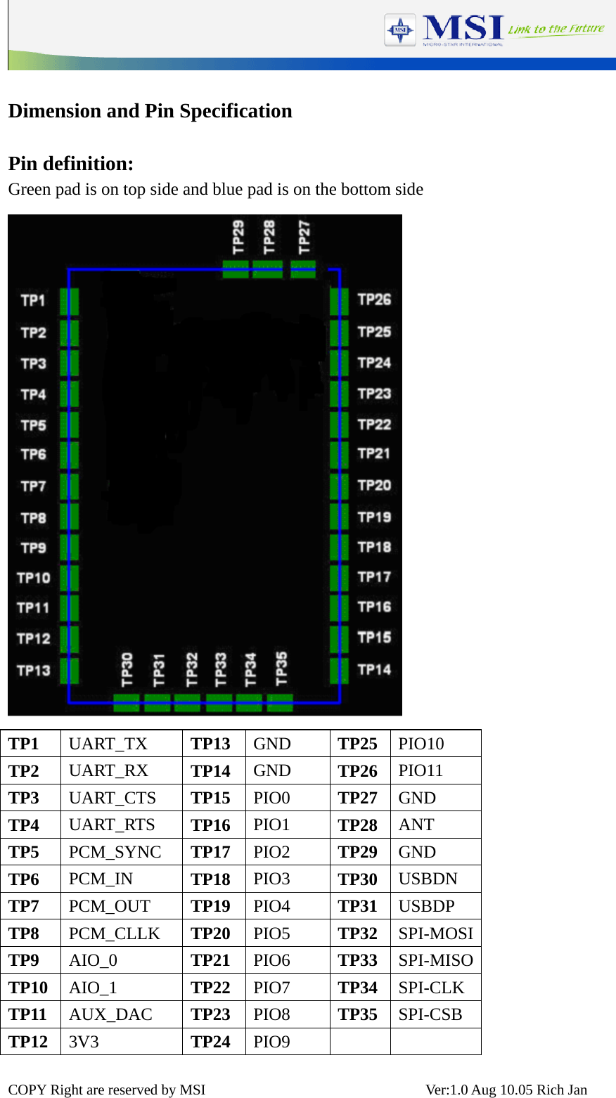
Micro Star MS6837 Bluetooth Module User Manual users manual
Micro Star International Co Ltd Bluetooth Module users manual
UserManual.wiki
>
Micro Star
>
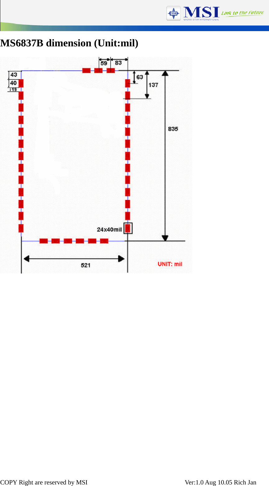
MS6837 User Manual
users manual
Navigation menu
Upload a User Manual
Namespaces
Wiki Guide
HTML
PDF
Info
Views
User Manual
Discussion / Help
Navigation