Micro Star MS6837 Bluetooth Module User Manual users manual
Micro Star International Co Ltd Bluetooth Module users manual
users manual
COPY Right are reserved by MSI Ver:1.0 Aug 10.05 Rich Jan
COPY Right are reserved by MSI Ver:1.0 Aug 10.05 Rich Jan
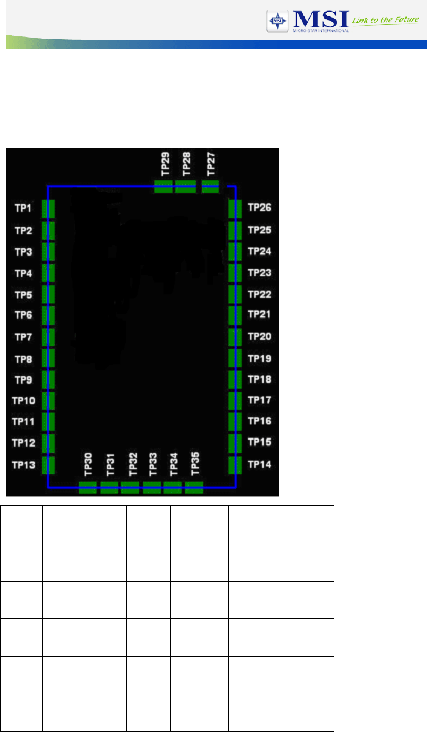
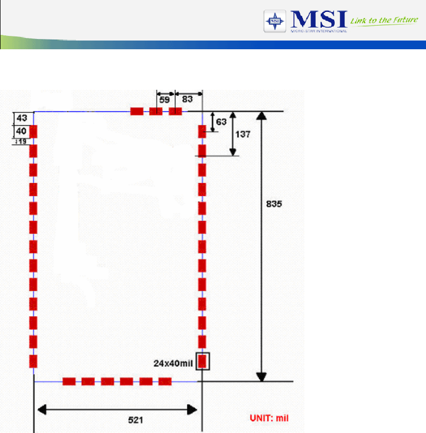
Dimension and Pin Specification
Pin definition:
Green pad is on top side and blue pad is on the bottom side
TP1 UART_TX TP13 GND TP25 PIO10
TP2 UART_RX TP14 GND TP26 PIO11
TP3 UART_CTS TP15 PIO0 TP27 GND
TP4 UART_RTS TP16 PIO1 TP28 ANT
TP5 PCM_SYNC TP17 PIO2 TP29 GND
TP6 PCM_IN TP18 PIO3 TP30 USBDN
TP7 PCM_OUT TP19 PIO4 TP31 USBDP
TP8 PCM_CLLK TP20 PIO5 TP32 SPI-MOSI
TP9 AIO_0 TP21 PIO6 TP33 SPI-MISO
TP10 AIO_1 TP22 PIO7 TP34 SPI-CLK
TP11 AUX_DAC TP23 PIO8 TP35 SPI-CSB
TP12 3V3 TP24 PIO9
COPY Right are reserved by MSI Ver:1.0 Aug 10.05 Rich Jan
MS6837B dimension (Unit:mil)
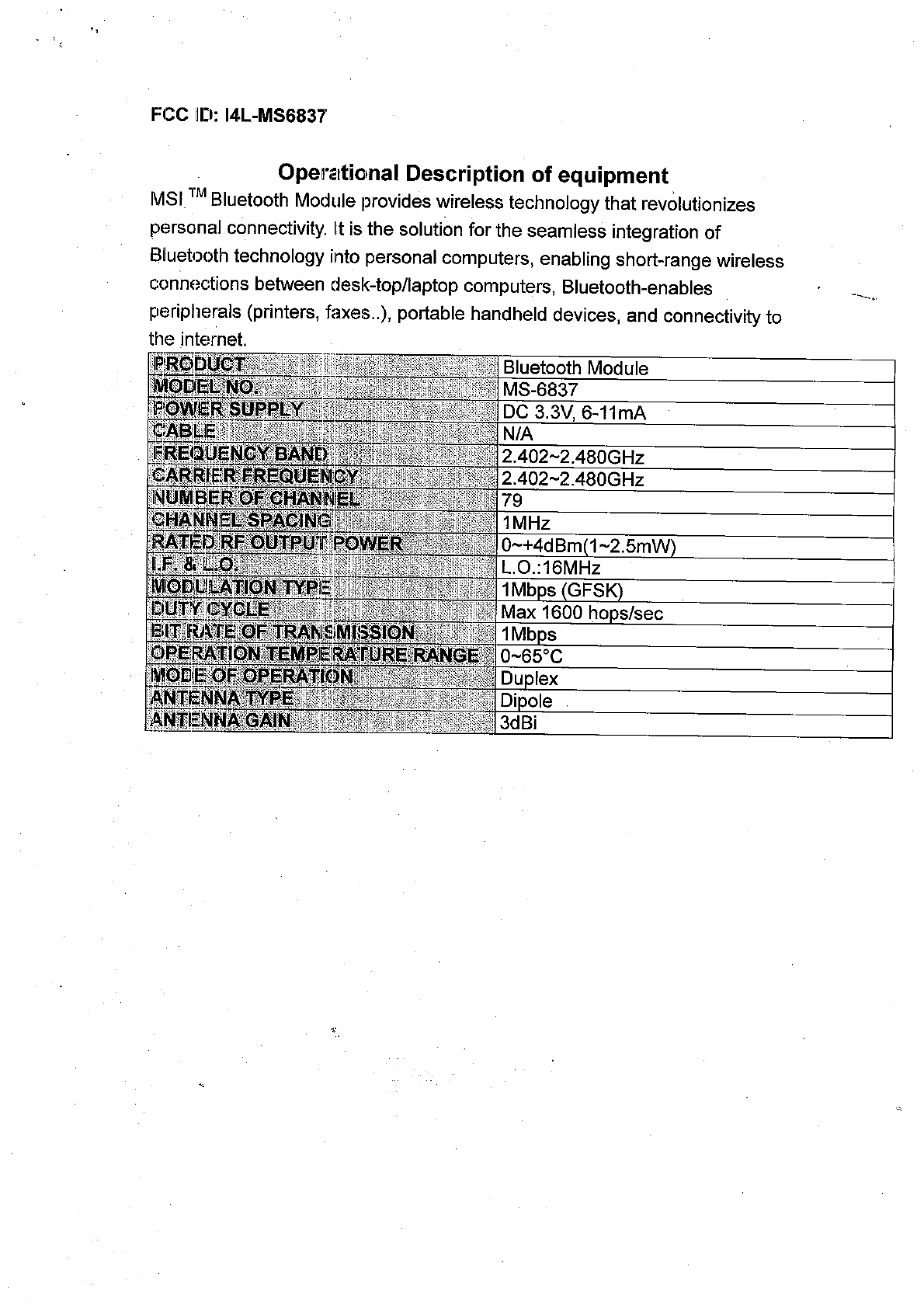
Federal Communications Commission (FCC) Statement
RADIO FREQUENCY INTERFERENCE BTATEMENT
This device complies with Part 15 of the FCC rules. Operation is subject to the following two
conditions:
1) this device may not cause harmful interference, and
2) this device must accept any interference received, including interference that may cause
undesired operation.
This equipment has been tested and found to comply with the limits for a Class B digital device,
pursuant to Part 15 of the FCC rules. These limits are designed to provide reasonable
protection against harmful interference in a residential installation. This equipment generates,
uses and can radiate radio frequency energy and if not installed and used in accordance with
the instructions, may cause harmful interference to radio communications. However, there is
no guarantee that interference will not occur in a particular installation. If this equipment does
cause harmful interference to radio or television reception, which can be determined by turning
the equipment off and on, the user is encouraged to try correct the interference by one or more
of the following measures:
- Reorient the receiving antenna.
- Increase the separation between the equipment and receiver.
- Connect the equipment into and outlet on a circuit different from that to which the
receiver is connected.
- Consult the dealer or an experienced radio/TV technician for help.
Warning: A shielded-type power cord is required in order to meet FCC emission limits
and also to prevent interference to the nearby radio and television reception. It is
essential that only the supplied power cord be used.
Use only shielded cables to connect I/O devices to this equipment.
CAUTION:
1. Any changes or modifications not expressly approved by the party responsible for
compliance could void your authority to operate the equipment.
2. The antenna(s) used for this transmitter must not be co-located or operating in
conjunction with any other antenna or transmitter.
3. The modular transmitter must be labeled with its own FCC ID number, and if the FCC
ID is not visible when the module is installed inside another device, then the outside of
the device into which the module is installed must also display a label referring to the
enclosed module. This exterior label can use wording such as the following:
“ Contains Transmitter Module FCC ID:XYZMODEL1” or “Contains FCC
ID:XYZMODEL1.”