MicroRidge Systems RM2 2.4GHz Radio Module User Manual Micro RM24 Users Guide Ver 1 2 4
MicroRidge Systems, Inc. 2.4GHz Radio Module Micro RM24 Users Guide Ver 1 2 4
Users Manual
All rights reserved. No parts of this work may be reproduced in any form or by any means - graphic, electronic, or
mechanical, including photocopying, recording, taping, or information storage and retrieval systems - without the written
permission of the publisher.
Products that are referred to in this document may be either trademarks and/or registered trademarks of the respective
owners. The publisher and the author make no claim to these trademarks.
While every precaution has been taken in the preparation of this document, the publisher and the author assume no
responsibility for errors or omissions, or for damages resulting from the use of information contained in this document or
from the use of programs and source code that may accompany it. In no event shall the publisher and the author be liable
for any loss of profit or any other commercial damage caused or alleged to have been caused directly or indirectly by this
document.
Version: 1.2.4
Printed: Friday, October 31, 2014 at 10:02 AM in Sunriver, Oregon.
MicroRidge 2.4 GHz Radio Module
Copyright © 2014 MicroRidge Systems, Inc.

IContents
Copyright © 2014 MicroRidge Systems, Inc.
MicroRidge 2.4 GHz Radio Module
Version 1.2.4
Table of Contents
Chapter 1 1
...................................................................................................................................
Introduction
Chapter 2 3
...................................................................................................................................
Features
Chapter 3 4
...................................................................................................................................
Releated Documents
Chapter 4 5
...................................................................................................................................
Specifications
...................................................................................................................................
Atmel Documentation 5
...................................................................................................................................
Dimensions 7
...................................................................................................................................
Pin Configuration 10
...................................................................................................................................
Soldering 12
Chapter 5 13
...................................................................................................................................
Application Board Design
Chapter 6 15
...................................................................................................................................
Ordering Information
Chapter 7 16
...................................................................................................................................
Radio Certification
Chapter 8 18
...................................................................................................................................
Contact MicroRidge
Chapter 9 19
...................................................................................................................................
Revision History
Introduction 1
Copyright © 2014 MicroRidge Systems, Inc.
MicroRidge 2.4 GHz Radio Module
Version 1.2.4
1Introduction
The MICRO-RM2.4 Radio Module from MicroRidge Systems is a small wireless module based
on the Atmel ATmega2564RFR2 microcontroller. The ATmega2564RFR2 is a low-powered
CMOS 8-bit microcontroller based on the AVR enhanced RISC architecture combined with a high
data rate transceiver for the 2.4 GHz ISM (industrial, scientific and medical) band.
The MICRO-RM2.4 contains an on-board chip antenna. The module contains radio certifications
for FCC, IC and EU (CE). No additional RF testing is required as long as the application of the
MICRO-RM2.4 follows the approved certifications.
The small size of the MICRO-RM2.4 module allows it to be used in small and compact products.
The module measures 12 x 20.75 x 3 mm (.472 x .817 x .118 inches). The module requires a
power supply of 1.8 to 3.6 volts DC. This voltage range allows the module to be powered by a
single 3 volt coin cell or two 1.5 volt batteries.
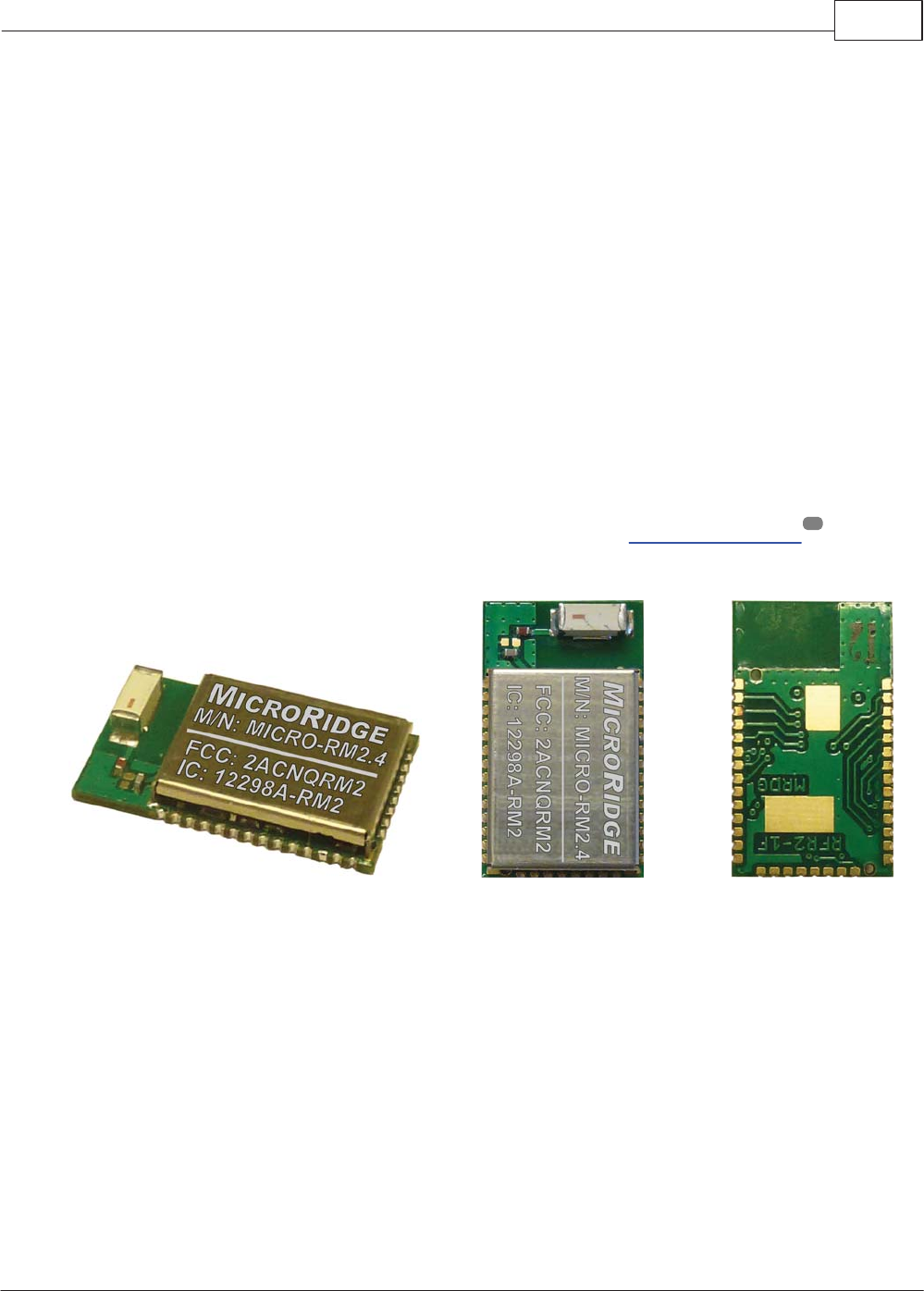
Radio Module Images
The photos below show the top and bottom views of the radio module. The 2 large gold pads
shown in the bottom view are the ground pads discussed in the Dimensions section .
Isometric View Top View Bottom View
7
Introduction 2
Copyright © 2014 MicroRidge Systems, Inc.
MicroRidge 2.4 GHz Radio Module
Version 1.2.4
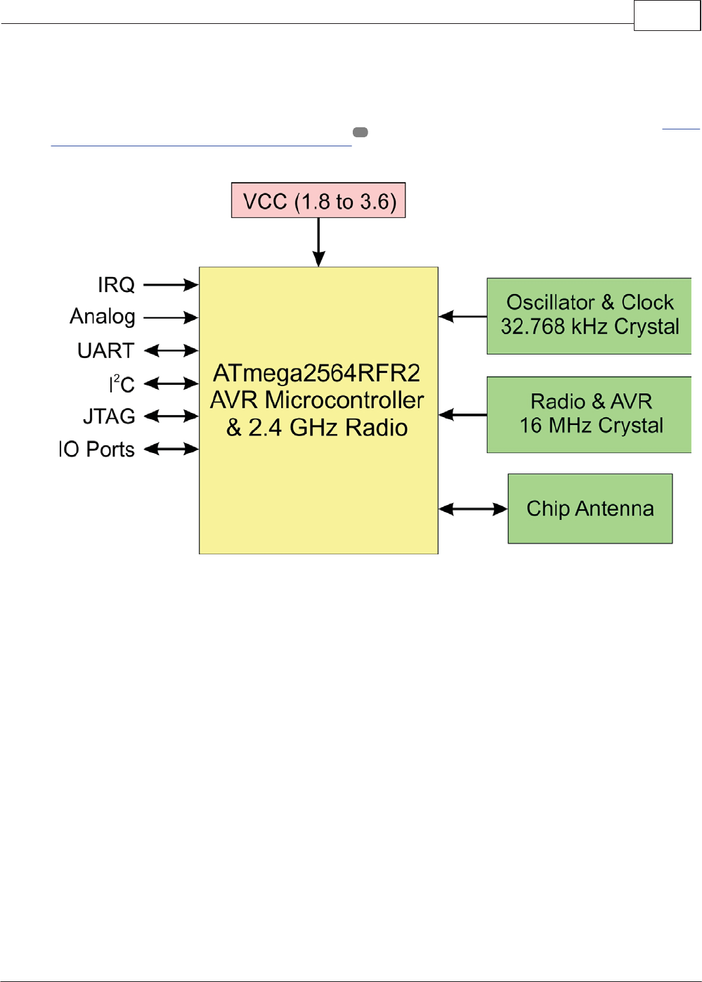
Basic Block Diagram
A basic block diagram of the MICRO-RM2.4 Radio Module is shown below. Refer to the Atmel
ATmega644/1284/2564RFR2 documentation for block diagrams with greater detail.
4

Features 3
Copyright © 2014 MicroRidge Systems, Inc.
MicroRidge 2.4 GHz Radio Module
Version 1.2.4
2Features
The features of the MICRO-RM2.4 Radio Module are numerous and allow the module to be used
in many low powered short range applications. The primary features of this module are as
follows:
Ultra compact size: 12 x 20.75 x 3 mm (.472 x .817 x .118 inches)
Built-in 32.768 kHz crystal for low power and deep sleep modes
Built-in 16 MHz crystal for 2.4 GHz transceiver and AVR microcontroller
Power supply voltage of 1.8 to 3.6 VDC
Typical power consumption:
o0.75 A in sleep mode (transceiver in Sleep and AVR in Power Save/Down mode)
o14.5 ma in TX mode at 3.5 dBm
o12.5 ma in RX mode
Memory resources:
o256K bytes In-System Self-Programmable Flash
o8K bytes EEPROM
o32K bytes SRAM
IEEE® 802.15.4 compliant transceiver
2.4 GHz ISM band
TX/RX 128 byte frame buffer
TX output power from -17 dBm to 3.5 dBm
Receiver sensitivity = -100 dBm
14 RF Channels (11 to 25, channel 14 is reserved for internal use)
Serial bootloader
Interface connections:
o30 I/O ports
o2 RS-232 serial ports
oJTAG programming connection
oI2C
High performance low power AVR® 8-bit microcontroller
ROHS complainant
Extensive documentation and software resources available on the Atmel web site

Releated Documents 4
Copyright © 2014 MicroRidge Systems, Inc.
MicroRidge 2.4 GHz Radio Module
Version 1.2.4
3Releated Documents
Additional information is available about the MICRO-RM2.4 Radio Module components and
supporting software from the following sources:
A complete description of the ATmega2564RFR2 microcontroller used in the module is
available on the Atmel web site (www.atmel.com). The document describing this
microcontroller is ATmega644/1284/2564RFR2 42073A-MCU Wireless.
Atmel also has additional documentation available that may be helpful in developing
wireless applications for the MICRO-RM2.4 module.
The MicroRidge Wireless Communication Library is available to assist in the development
of firmware for the MICRO-RM2.4 Radio Module. A per module license is required in order
to use this Communication Library. This library is only supported on the IAR Embedded
Workbench Ver 6.4 or later for the AVR microcontroller. Contact MicroRidge Systems for
more information.
18
Specifications 5
Copyright © 2014 MicroRidge Systems, Inc.
MicroRidge 2.4 GHz Radio Module
Version 1.2.4
4Specifications
The specifications sections consists of 4 areas:
Atmel Documentation This section contains 3 of the tables from the Atmel
ATmega644/1284/2564RFR2 documentation. The complete Atmel
document is over 600 pages in length. In order to fully understand
the radio module and how to work with it, you must become
familiar with this Atmel document.
Dimensions The dimensions for the MICRO-RM2.4 Radio Module, pad
locations and bottom side ground pads are presented in this
section.
Pin Configuration The pin connections available on the MICRO-RM2.4 Radio
Module are listed in this section.
Soldering A soldering profile is shown in this section.
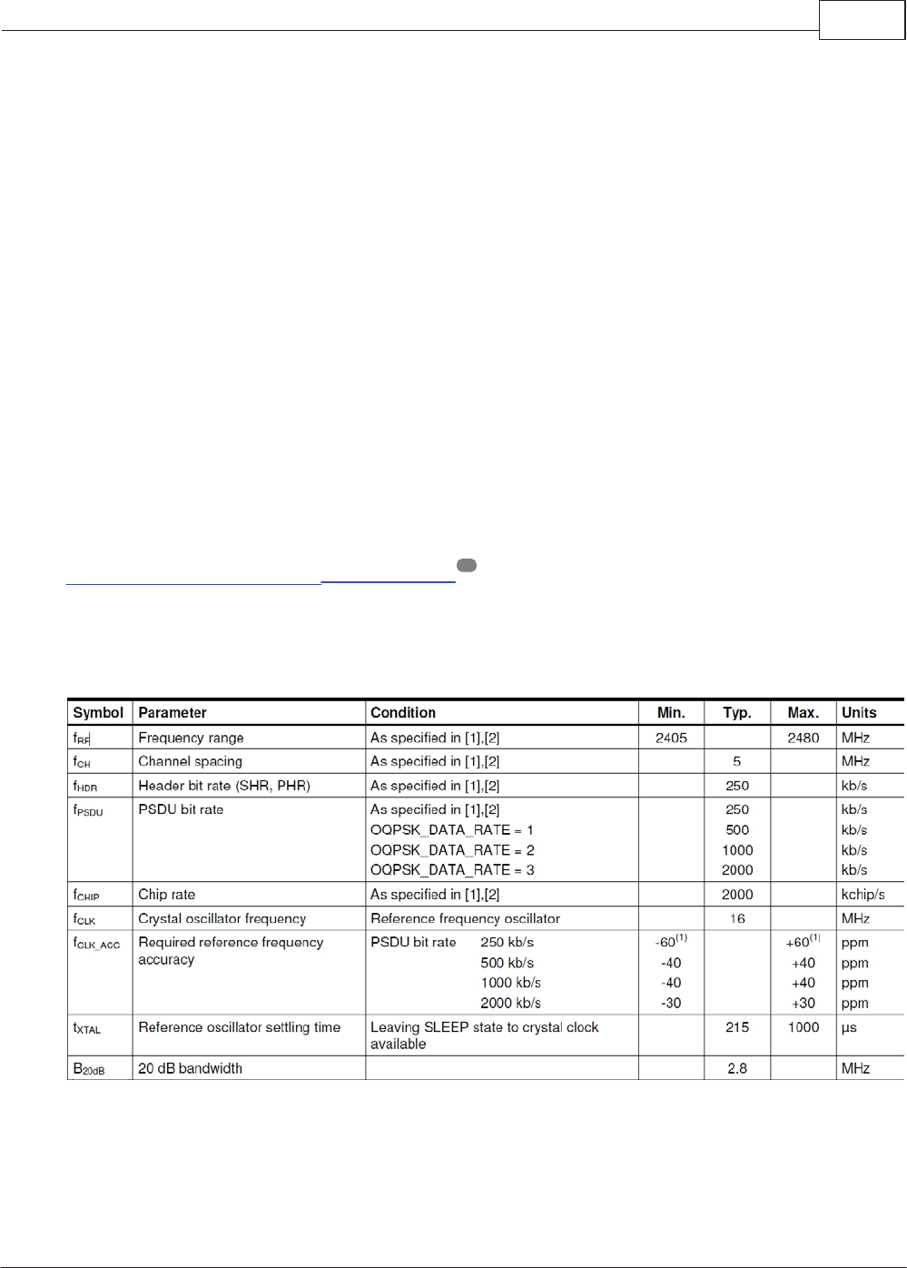
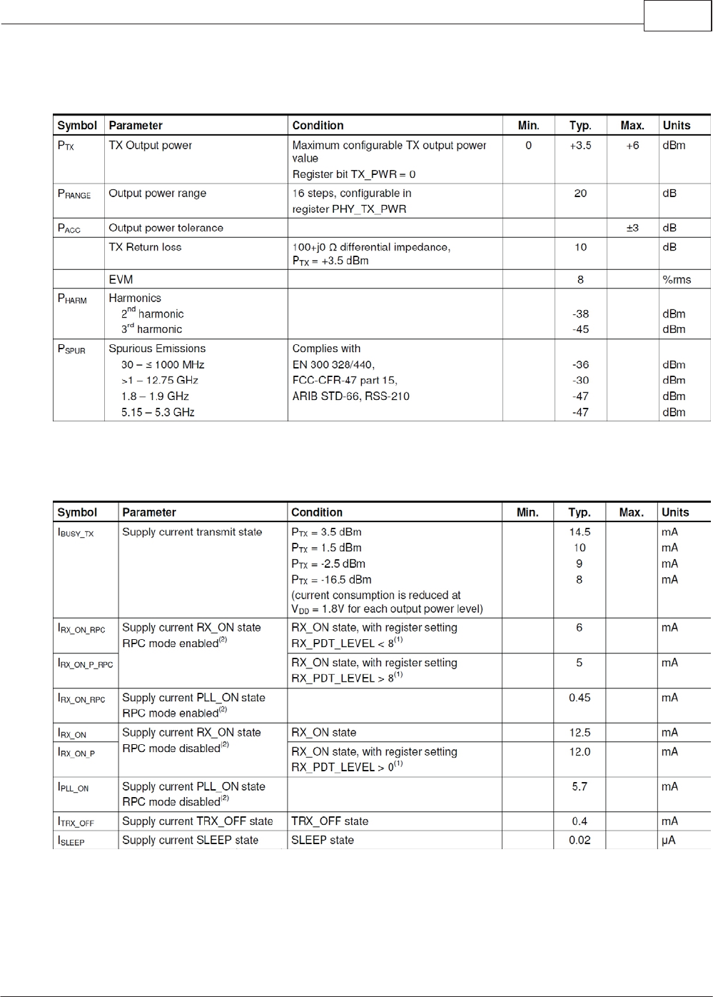
4.1 Atmel Documentation
For the complete specifications for the Atmel ATmega2564RFR2 radio transceiver refer to
ATmega644/1284/2564RFR2 documentation . The information shown below is only a few of
the multiple tables from the Atmel documentation. Refer to the Atmel documentation for the test
conditions and references shown in the tables.
General RF Specifications
4
Specifications 6
Copyright © 2014 MicroRidge Systems, Inc.
MicroRidge 2.4 GHz Radio Module
Version 1.2.4
Transmitter characteristics
Current Consumptions Specifications
Specifications 7
Copyright © 2014 MicroRidge Systems, Inc.
MicroRidge 2.4 GHz Radio Module
Version 1.2.4
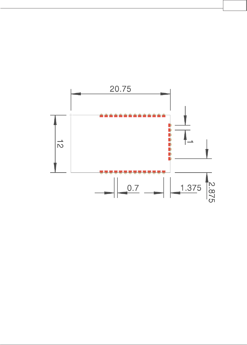
4.2 Dimensions
Board Dimensions
The dimensions for the MICRO-RM2.4 Radio Module are given below. All of the dimensions are
in mm. The thickness of the module from the bottom of the module to the top of the RF shield is
3 mm. The pad spacing is 1 mm and the pad width is 0.7 mm.
Board Dimensions (mm) and Solder Pad Placement
Specifications 8
Copyright © 2014 MicroRidge Systems, Inc.
MicroRidge 2.4 GHz Radio Module
Version 1.2.4
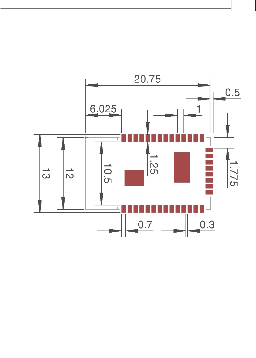
Solder Pad Placement
The recommended placement of the solder pads on the application board is shown below. The
2 large pads are ground pads and they are discussed in the Ground Pads. All dimensions are in
mm.
Specifications 9
Copyright © 2014 MicroRidge Systems, Inc.
MicroRidge 2.4 GHz Radio Module
Version 1.2.4
Ground Pads
The bottom of the module contains 2 ground (GND) pads areas that can be used to help secure
the module to the circuit board. In a rough environment, we have seen delamination problems
with this type of module board. When adhesive was used to help secure the module board to
the application circuit board, we no longer had any delamination problems between the module
and application circuit boards. In the stuffing process, the board house can use an adhesive to
help secure the wireless module to the application circuit board or solder the ground pads to the
application circuit board..
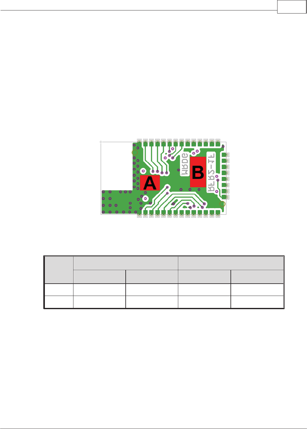
The 2 ground pads are available on the bottom side of the wireless module. These ground pads
are shown in red and labeled A and B. These 2 pad areas are part of the bottom ground plane.
Location of the Ground Pads on the Bottom of the Wireless Module
The size and location of the ground pads is shown in the following table.
Ground
Pad
Size Distance from Upper Left Corner
Width, mm Height, mm Horizontal, mm Vertical, mm
A3.25 2.50 6.50 5.50
B2.625 5.00 14.75 2.50
Specifications 10
Copyright © 2014 MicroRidge Systems, Inc.
MicroRidge 2.4 GHz Radio Module
Version 1.2.4
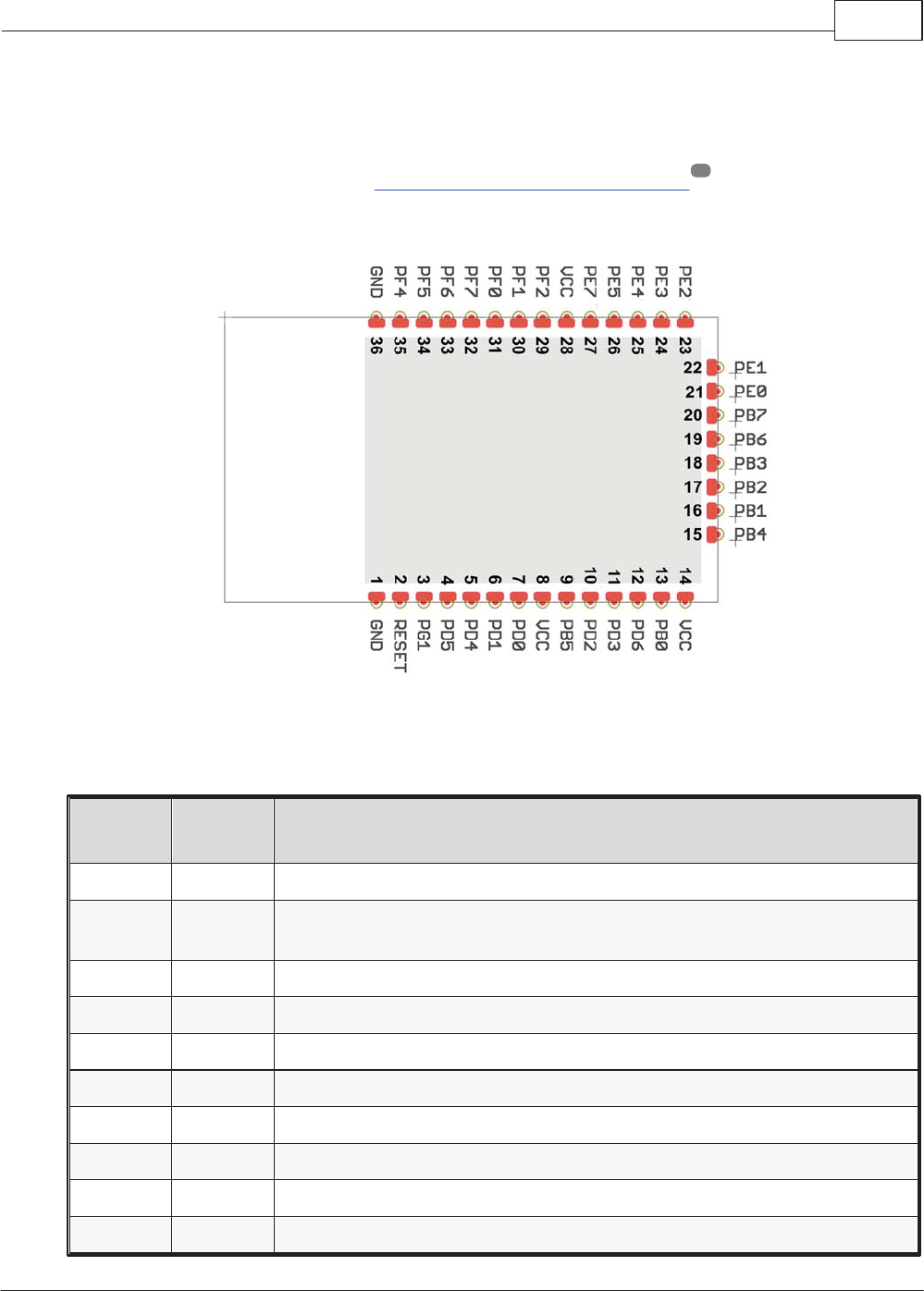
4.3 Pin Configuration
The pin connections for the MICRO-RM2.4 Radio Module are show below. For a complete
description of each pin refer to the Atmel ATmega644/1284/2564RFR2 documentation.
MICRO-RM2.4 Pin Connections
Module
Pin
Pin
Name Description
1 GND Ground (connected to AVSS_RFP, AVSS_RFN, DVSS & AVSS)
2RESET Reset input (active low). The radio module also contains a 100K pullup
resistor connected between this pin and VCC.
3PG1 Port PG1
4PD5 Port PD5 (alternate function XCK1)
5PD4 Port PD4 (alternate function ICP1)
6PD1 Port PD1 (alternate functions SDA & INT1)
7PD0 Port PD0 (alternate functions SCL & INT0)
8VCC 1.8 to 3.6 VDC (connected to DEVDD & EVDD)
9PB5 Port PB5 (alternate functions OC1A & PCINT5)
10 PD2 Port PD2 (alternate functions RXD1 & INT2)
4
Specifications 11
Copyright © 2014 MicroRidge Systems, Inc.
MicroRidge 2.4 GHz Radio Module
Version 1.2.4
Module
Pin
Pin
Name Description
11 PD3 Port PD3 (alternate functions TXD1 & INT3)
12 PD6 Port PD6 (alternate function T1)
13 PB0 Port PB0 (alternate functions SSN & PCINT0)
14 VCC 1.8 to 3.6 VDC (connected to DEVDD & EVDD)
15 PB4 Port PB4 (alternate functions OC2A & PCINT4)
16 PB1 Port PB1 (alternate functions SCK & PCINT1)
17 PB2 Port PB2 (alternate functions MOSI, PDI & PCINT2)
18 PB3 Port PB3 (alternate functions MISO, PDO & PCINT3)
19 PB6 Port PB6 (alternate functionsOC1B & PCINT6)
20 PB7 Port PB7 (alternate functions OC0A, OC1C & PCINT7)
21 PE0 Port PE0 (alternate functions RXD0 & PCINT8)
22 PE1 Port PE1 (alternate function TXD0)
23 PE2 Port PE2 (alternate functions XCK0 & AIN0)
24 PE3 Port PE3 (alternate functions OC3A & AIN1)
25 PE4 Port PE4 (alternate functions OC3B & INT4)
26 PE5 Port PE5 (alternate functions OC3C & INT5)
27 PE7 Port PE7 (alternate functions ICP3, INT7 & CLK)
28 VCC 1.8 to 3.6 VDC (connected to DEVDD & EVDD)
29 PF2 Port PF2 (alternate function ADC2)
30 PF1 Port PF1 (alternate function ADC1)
31 PF0 Port PF0 (alternate function ADC0)
32 PF7 Port PF7 (alternate functions JTAG TDI & ADC7)
33 PF6 Port PF6 (alternate functions JTAG TDO & ADC6)
34 PF5 Port PF5 (alternate functions JTAG TMS & ADC5)
35 PF4 Port PF4 (alternate functions JTAG TCK, PF3 & ADC3)
36 GND Ground (connected to AVSS_RFP, AVSS_RFN, DVSS & AVSS)
-- PD7 Port PD7. Do not use. This ports is used internally by the wireless
module.
-- TST Connected to GND in the wireless module.
-- CLKI Connected to GND in the wireless module.
Specifications 12
Copyright © 2014 MicroRidge Systems, Inc.
MicroRidge 2.4 GHz Radio Module
Version 1.2.4
Module
Pin
Pin
Name Description
-- TOSC1 Connected to 32.768 KHz crystal in the wireless module.
-- TOSC2 Connected to 32.768 KHz crystal in the wireless module.
-- XTAL1 Connected to 16 MHz crystal in the wireless module.
-- XTAL2 Connected to 16 MHz crystal in the wireless module.
4.4 Soldering
The following J-STD-020C compliant soldering profile is recommended for the MICRO-RM2.4
Radio Module. Since the FCC and IC IDs are etched into the RF shield, there is no concern
about heat form the soldering process damaging a label that contains this ID information.
Profile Feature Values
Average ramp-up rate (217°C to peak) 3°C/s max
Preheat temperature 175°C ±25°C 180s max
Temperature maintained above 217°C 60s to 150s
Time within 5°C of actual peak temperature 20s to 40s
Peak temperature range 260°C
Ramp-down rate 6°C/s max
Time within 25°C to peak temperature 8 minutes
Application Board Design 13
Copyright © 2014 MicroRidge Systems, Inc.
MicroRidge 2.4 GHz Radio Module
Version 1.2.4
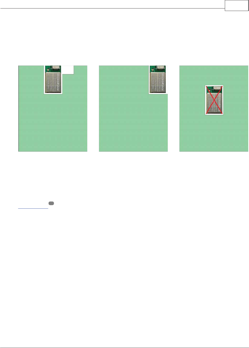
5Application Board Design
Normally, chip antennas are more tolerant of the board and enclosure materials. However, the
recommendations for the radio module placement on the application PCB still apply. The radio
module should be placed along an edge of the application PCB as shown below.
Module placed along top
edge of PCB.
Module placed along top
edge of PCB.
Module placed in center
portion of PCB.
Not an acceptable design.
Mounting Information
In general, via holes and traces are should not be placed on the application PCB upper layer in
the area occupied by the radio module module. The exception to this is if you are soldering the
ground pads to the PCB board, you can use via holes and/or traces to connect the pads to the
ground. Be careful that you do not place any via holes or traces adjacent to non-ground
circuits.
The ground connections along the edges of the radio module should be grounded by via holes
located as close as possible to the ground connections on the radio module.
Via Placement
The board design should prevent propagation of microwave fields inside the board material.
Electromagnetic waves of high frequency may penetrate the board thus making the edges of the
board radiate, which may distort the antenna pattern. To eliminate this effect, via holes should be
placed around the board's edges. A common rule of thumb is to make the via spacing less than
λ/20 at the maximum operating frequency. For the MICRO-RM2.4 Radio Module, the wavelength
at 2.4 GHz is 125 mm and the maximum via spacing would be 6.25 mm.
9

Application Board Design 14
Copyright © 2014 MicroRidge Systems, Inc.
MicroRidge 2.4 GHz Radio Module
Version 1.2.4
Other Recommendations
Metal enclosure should not be used.
Low profile enclosures might affect antenna antenna performance.
Avoid placing high profile components next to antenna.
Radio module should not be placed next to other electronics which might interfere with the
2.4 GHz frequency band.

Ordering Information 15
Copyright © 2014 MicroRidge Systems, Inc.
MicroRidge 2.4 GHz Radio Module
Version 1.2.4
6Ordering Information
Contact MicroRidge Systems to order MICRO-RM2.4 Radio Modules. The packaging options
of tray, and tape and reel are still being evaluated. There are also software options available for
the radio modules.
18

Radio Certification 16
Copyright © 2014 MicroRidge Systems, Inc.
MicroRidge 2.4 GHz Radio Module
Version 1.2.4
7Radio Certification
United States (FCC)
This device complies with part 15 of the FCC rules. Operation is subject to the following two
conditions: (1) This device may not cause harmful interference, and (2) this device must accept
any interference received, including interference that may cause undesired operation. Any
changes or modifications not expressly approved by manufacturer could void the user’s authority
to operate the equipment.
IMPORTANT! Any changes or modifications not expressly approved by the party responsible for
compliance could void the user’s authority to operate this equipment.
47 CFR 15.505
For a Class B digital device or peripheral, the instructions furnished the user shall include the
following or similar statement, placed in a prominent location in the text of the manual:
NOTE: This equipment has been tested and found to comply with the limits for a Class B digital
device, pursuant to part 15 of the FCC Rules. These limits are designed to provide reasonable
protection against harmful interference in a residential installation. This equipment generates,
uses and can radiate radio frequency energy and, if not installed and used in accordance with
the instructions, may cause harmful interference to radio communications. However, there is no
guarantee that interference will not occur in a particular installation. If this equipment does
cause harmful interference to radio or television reception, which can be determined by turning
the equipment off and on, the user is encouraged to try to correct the interference by one or
more of the following measures:
Reorient or relocate the receiving antenna.
Increase the separation between the equipment and receiver.
Connect the equipment into an outlet on a circuit different from that to which the receiver is
connected.
Consult the dealer or an experienced radio/ TV technician for help.
The modular transmitter must be labeled with its own FCC ID number, and, if the FCC ID is not
visible when the module is installed inside another device, then the outside of the device into
which the module is installed must also display a label referring to the enclosed module. This
exterior label can use wording such as the following:
Contains FCC ID: 2ACNQRM2
The MICRO-RN2.4 Radio Module has a Modular approval and does not need separate approval
for this module when used on an application board.
Industry Canada (IC)
This device complies with Industry Canada licence-exempt RSS standard(s). Operation is
subject to the following two conditions: (1) this device may not cause interference, and (2) this
device must accept any interference, including interference that may cause undesired operation
of the device.

Radio Certification 17
Copyright © 2014 MicroRidge Systems, Inc.
MicroRidge 2.4 GHz Radio Module
Version 1.2.4
Le présent appareil est conforme aux CNR d’Industrie Canada applicables aux appareils radio
exempts de licence. L’exploitation est autorisée aux deux conditions suivantes: (1) l’appareil ne
doit pas produire de brouillage, et (2) l’utilisateur de l’appareil doit accepter tout brouillage
radioélectrique subi, meme si le brouillage est susceptible d’en compromettre le fonctionnement.
IMPORTANT! Tous les changements ou modifications pas expressément approuvés par la
partie responsable de la conformité ont pu vider l’autorité de l’utilisateur pour actioner cet
équipment.
This Class [B] digital apparatus complies with Canadian ICES-003.
Cet appareil numérique de la classe [B] est conforme à la norme NMB-003 du Canada
This modular transmitter must be labeled with its own IC ID. If the IC ID Certification Number is
not visible while installed inside another device, then the device should display the label on it
referring the enclosed module. In that case, the final end product must be labeled in a visible
area with the following:
Contains IC: 12298A-RM2
The MICRO-RN2.4 Radio Module has a Modular approval and does not need separate approval
for this module when used on an application board.
European Union (ETSI)
The MICRO-RN2.4 module has been certified for use in European Union countries. If this
module is incorporated into a product, the manufacturer must ensure compliance of the final
product to the European harmonized EMC and low voltage/safety standards. A Declaration of
Conformity must be issued for each of these standards and kept on file as described in Annex II
of the R&TTE Directive.
Furthermore, the manufacturer must maintain a copy of the modules' documentation and ensure
the final product does not exceed the specified power ratings, antenna specifications, and/or
installation requirements as specified in the user manual. If any of these specifications are
exceeded in the final product, a submission must be made to a notified body for compliance
testing to all required standards.
The 'CE' marking must be affixed to a visible location on the OEM product. The CE mark shall
consist of the initials "CE" taking the following form:
The CE marking must have a height of at least 5 mm except where this is not possible on
account of the nature of the apparatus.
The CE marking must be affixed visibly, legibly, and indelibly.
More detailed information about CE marking requirements you can find at "DIRECTIVE 1999/5/
EC OF THE EUROPEAN PARLIAMENT AND OF THE COUNCIL" on 9 March 1999 at section
12.

Contact MicroRidge 18
Copyright © 2014 MicroRidge Systems, Inc.
MicroRidge 2.4 GHz Radio Module
Version 1.2.4
8Contact MicroRidge
Email:
Support: support@microridge.com
Sales: sales@microridge.com
Information: info@microridge.com
Phone:
Support: 541.593.1656
Sales: 541.593.3500
Main office: 541.593.1656
Fax: 541.593.5652
Mailing Address:
MicroRidge Systems, Inc.
PO Box 3249
Sunriver, OR 97707-0249
Shipping Address:
MicroRidge Systems, Inc.
56888 Enterprise Drive
Sunriver, OR 97707
Note: There is no mail delivery to this address. This address should only be used for
package delivery services such as UPS, FedEx, etc.
Web: www.MicroRidge-RM.com
Revision History 19
Copyright © 2014 MicroRidge Systems, Inc.
MicroRidge 2.4 GHz Radio Module
Version 1.2.4
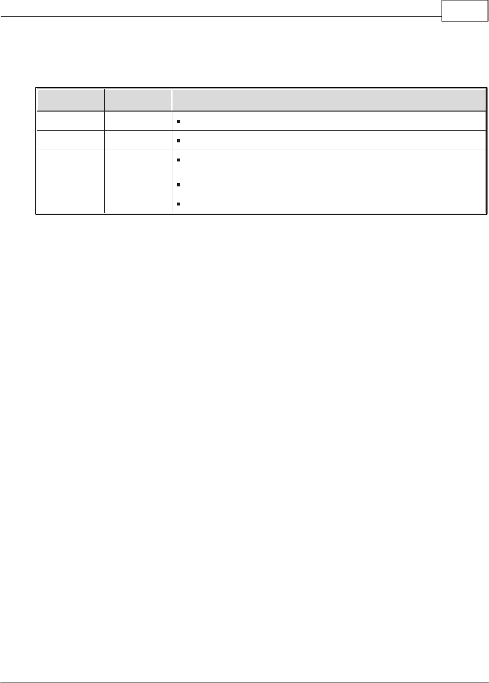
9Revision History
Date Version Comments
9-3-2014 1.0.1 Preliminary release of MICRO-RM2.4 User Manual
9-12-2014 1.1.2 Minor revisions to preliminary manual.
10-30-2014 1.2.3 Changed radio module images to reflect final FCC & IC
certification numbers.
Revised text for FCC and IC in Radio Certification section.
10-31-2014 1.2.4 Minor word additions to Radio Certification section.