MicroWeb MNC-W200 Network IP Camera User Manual 1
MicroWeb Co., Ltd. Network IP Camera 1
UserManual.wiki
>
MicroWeb
>
MNC-W200 User Manual
>
User Manual 1
Contents
1.
User Manual 1
2.
User Manual 2
User Manual 1
Navigation menu
Upload a User Manual
Namespaces
Wiki Guide
HTML
PDF
Info
Views
User Manual
Discussion / Help
Navigation
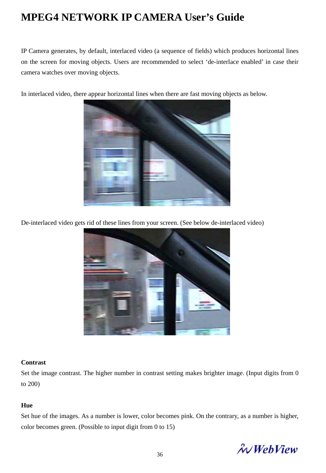
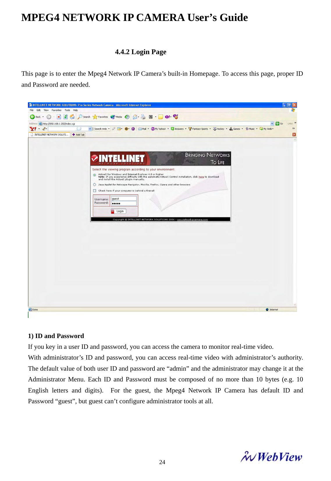
![MPEG4/JPEG Dual Mode Network IP Camera PROFESSIONAL SERIES User Manual [Model MNC-L200/MNC-W200] Revision 1.0.0](https://usermanual.wiki/MicroWeb/MNC-W200.User-Manual-1/User-Guide-764296-Page-1.png)
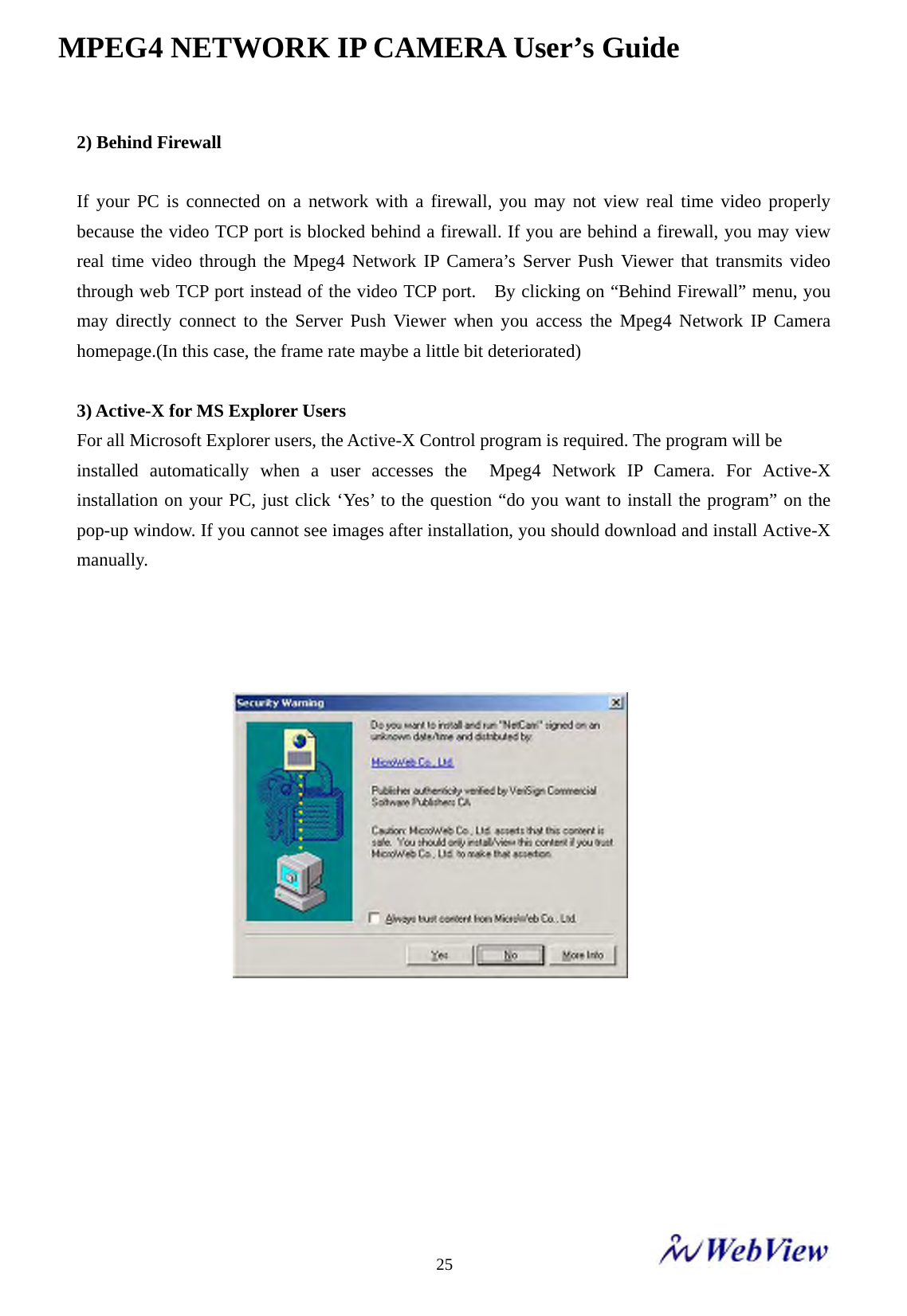
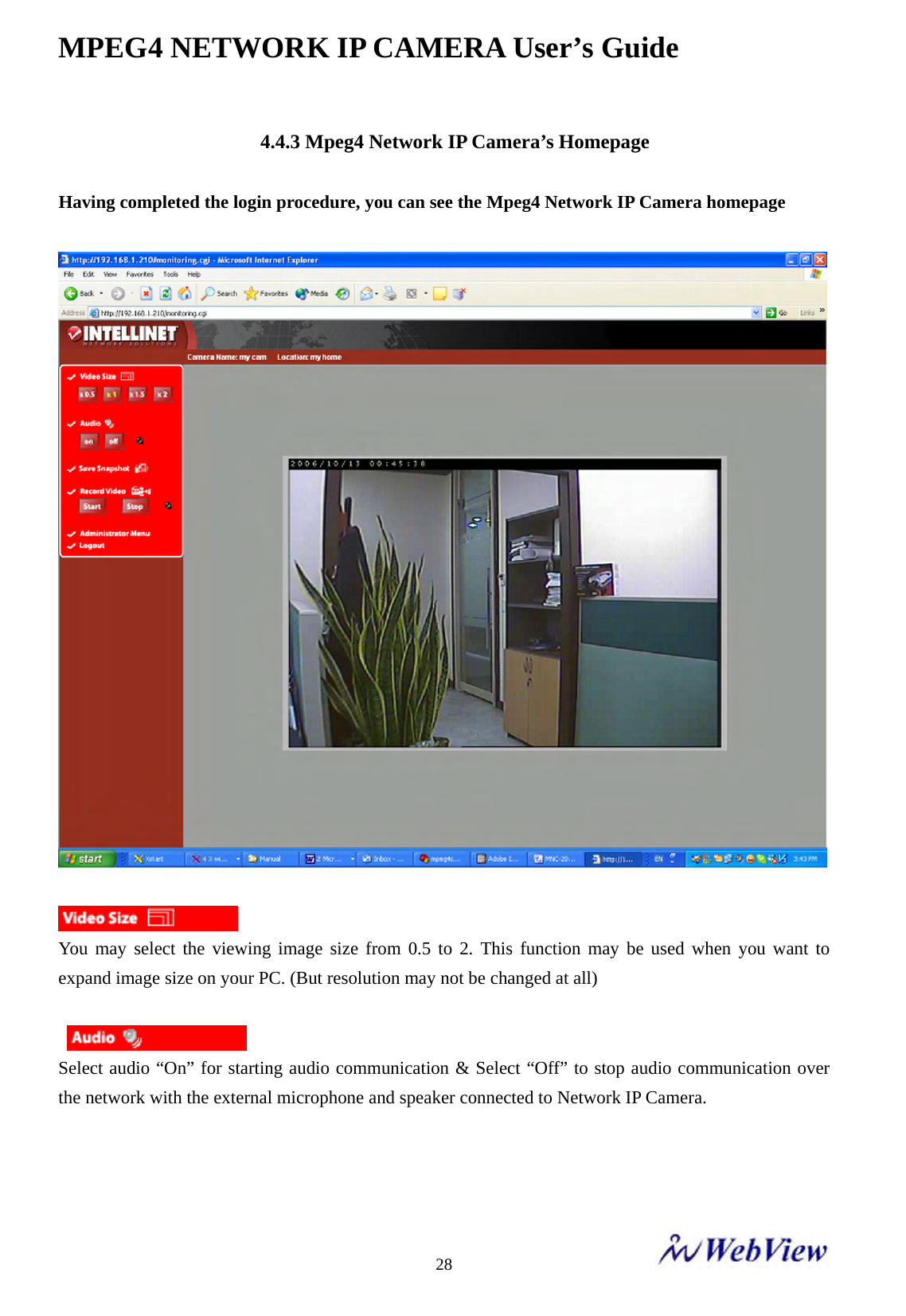
![This manual is intended for administrators and users of the WebView MPEG4/JPEG Dual Mode Network IP Camera[Model MNC-L200/MNC-W200], and is applicable for software release 1.4.0 and later. It includes instructions for using and managing the WebView MPEG4/JPEG Dual Mode Network IP Camera on your network. Previous experience of networking will be of use when using this product. Some knowledge of UNIX or Linux-based systems may also be beneficial, for developing shell scripts and applications. Later versions of this document will be posted to www.micro-web.co.kr , as required. FCC Statement This equipment generates, uses and can radiate radio frequency energy and, if not installed and used in accordance with the instructions, may cause harmful interference to radio communications. However, there is no guarantee that interference will not occur in a particular installation. If this equipment does cause harmful interference to radio or television reception, which can be determined by turning the equipment off and on, the user is encouraged to try to correct the interference by one or more of the following measures; - Re-orient or relocate the receiving antenna. - Increase the separation between the equipment and receiver. - Connect the equipment to an outlet on a different circuit to the receiver. - Consult your dealer or an experienced radio/TV technician for help. - Shielded (STP) network cables must be used with this unit to ensure compliance with EMC standards. This equipment has been tested and found to comply with the limits for Part 15 of FCC rules, which are designed to provide reasonable protection against such interference when operated in a commercial environment. Operation of this equipment in a residential area is likely to cause interference, in which case the user at his/her own expense will be required to take whatever measures may be required to correct the interference. FCC Caution : Any changes or modifications not expressly approved by the party responsible for compliance could void the user’s authority to operate this equipment. This device complies with Part 15 of FCC Rules. Operation of the device is subject to the following two conditions: (1) This device may not cause harmful interference, and (2) This device must accept any interference that may cause undesired operation.](https://usermanual.wiki/MicroWeb/MNC-W200.User-Manual-1/User-Guide-764296-Page-2.png)
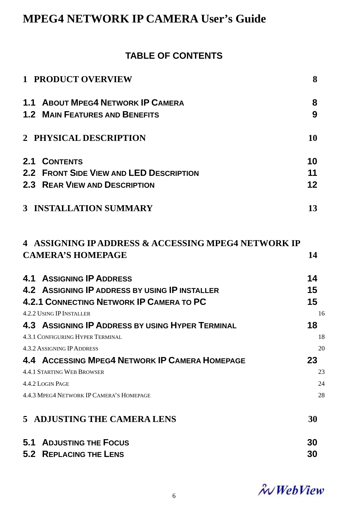
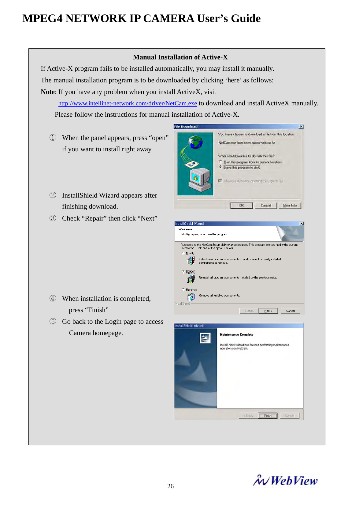
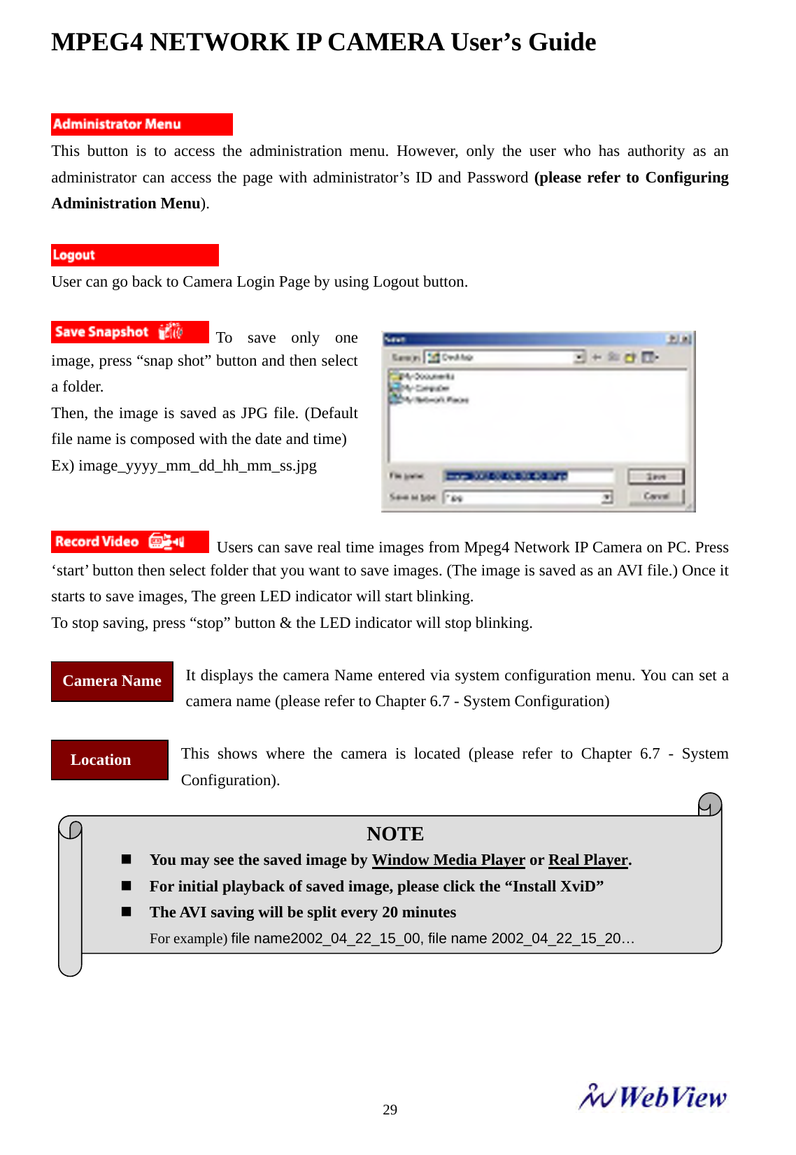
![MPEG4 NETWORK IP CAMERA User’s Guide 4 MNC-L200N : Wired MPEG4/JPEG Dual Mode Network IP Camera for NTSC standard MNC-L200P : Wired MPEG4/JPEG Dual Mode Network IP Camera for PAL standard MNC-W200N : Wireless and wired MPEG4/JPEG Dual Mode Network IP Camera for NTSC standard MNC-W200P : Wireless and wired MPEG4/JPEG Dual Mode Network IP Camera for PAL standard To determine your video standard, refer to the chart below ; PAL Afghanistan, Algeria, Argentina (N), Austria, Australia, Bangladesh, Belgium, Brazil (M), China, Denmark, Finland, Germany, Hong Kong, Iceland, India, Indonesia, Iraq, Ireland, Israel, Italy, Jordan, Kenya, Kuwait, Liberia, Malaysia, Netherlands, Nigeria, Norway, New Guinea, Pakistan, Singapore, South Africa, South W. Africa, Sudan, Sweden, Switzerland, Thailand, Turkey, Uganda, United Kingdom, United Arab Emirates, Yugoslavia, Zambia NTSC Canada, Chile, Costa Rica, Cuba, Dominican Republic, Ecuador, Japan, Mexico, Nicaragua, Panama, Peru, Philippines, Puerto Rico, South Korea, Taiwan, U.S.A. MPEG4/JPEG Dual Mode Network IP Camera Family [Model : MNC-L200/MNC-W200] User Manual Version 1.0.0 Oct. 2006](https://usermanual.wiki/MicroWeb/MNC-W200.User-Manual-1/User-Guide-764296-Page-4.png)

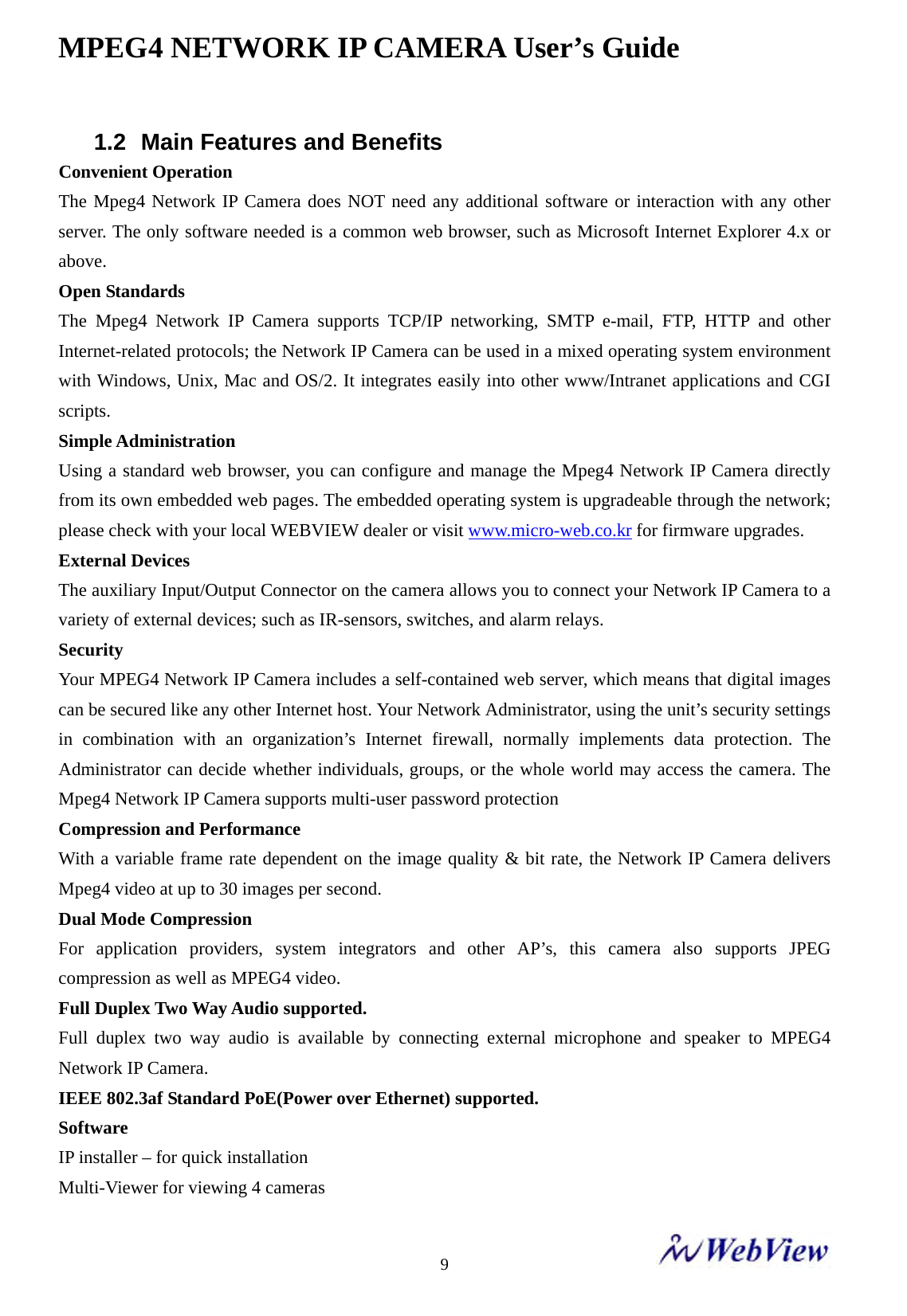
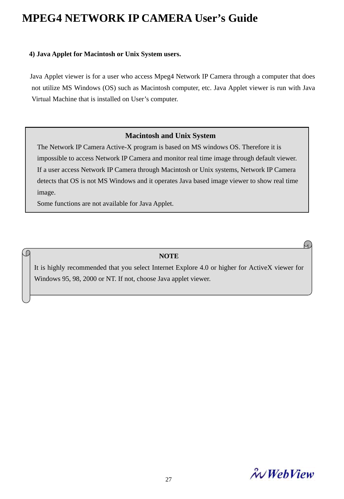
![MPEG4 NETWORK IP CAMERA User’s Guide 81 Product Overview 1.1 About Mpeg4 Network IP Camera [Model : MNC-L200] [Model : MNC-W200] The Mpeg4 Network IP Camera is an all-in-one networking device, which contains a digital color camera, powerful web server, optimized embedded operating system, hardware for image compression, and a physical Ethernet connection. The camera does not need any additional software or hardware. Simply provide power and connect an Ethernet Cable and view from any computer on the Network. The Mpeg4 IP Camera is ideal for surveillance applications that require high quality, full motion video and audio, as well as comparatively low bandwidth demands on the network. Mpeg4 Network IP Camera provides an easy user interface for remote access to receive the optimal synchronized video and audio from anywhere anytime over the Internet with the popular Internet Explorer Web Browser, as easy as surfing any regular Web sites. More than just a high-performance Network Camera, the Mpeg4 Network IP Camera also possesses many advanced features to provide the adequate personal or SI solutions, such as, Remote Surveillance, Home/Business Security, Audio/Video Conference, motion detection etc....](https://usermanual.wiki/MicroWeb/MNC-W200.User-Manual-1/User-Guide-764296-Page-8.png)
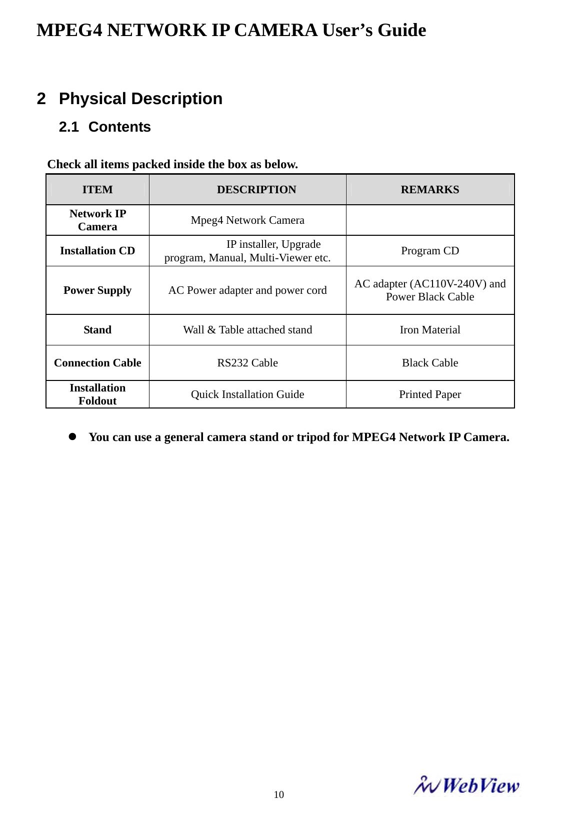
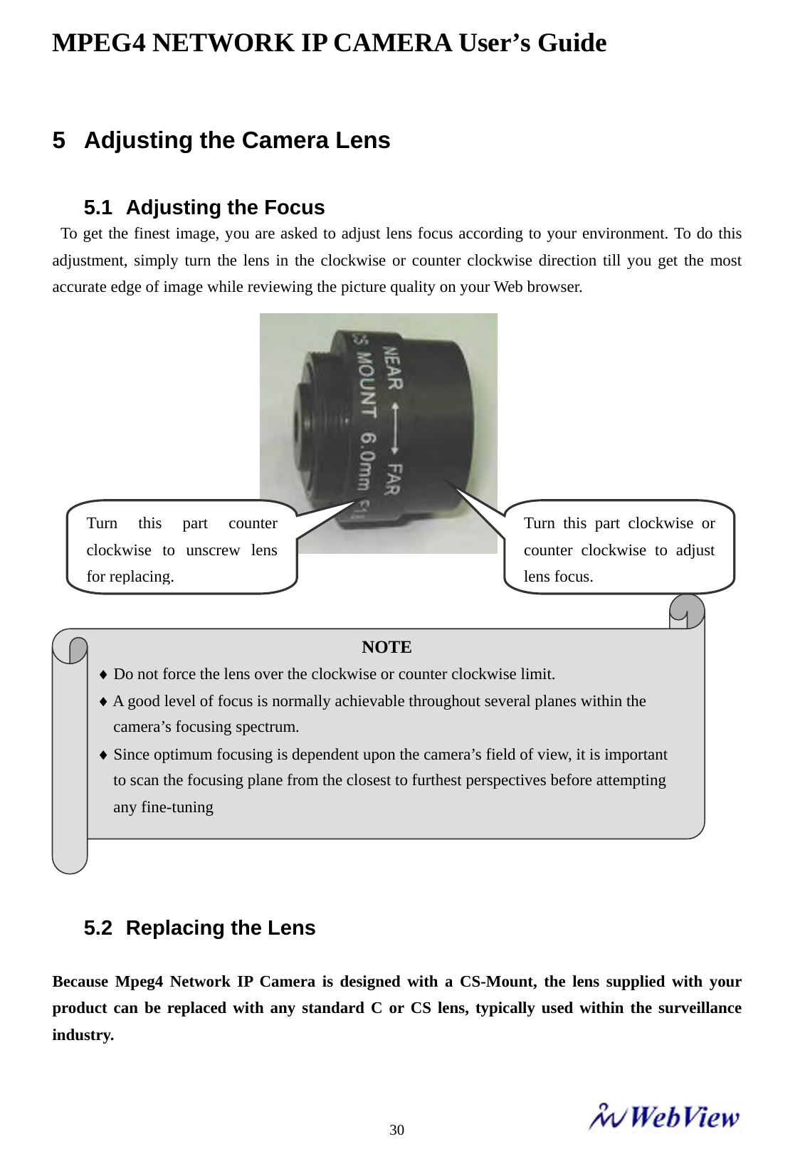
![MPEG4 NETWORK IP CAMERA User’s Guide 12 2.3 Rear View and Description Power Connector: Only use the supplied AC Adapter to avoid any possible damage from electric shock. Network Connector: Connect 10 baseT Ethernet or 100 base TX Fast Ethernet cable. GPIO Connector: To connect external devices such as infrared Sensors, alarms, or motion detectors (please refer to Appendix F – I/O Connectors). Mini DIN Connector: To connect external devices such as external Zoom/Focus Lens mechanism, or directly to a serial port for camera configuration via HyperTerminal (please refer to Appendix G - RS 232 Cable). SPK: Use to connect to external speaker for Audio communication. The Audio sent over N/w from Connected Camera client can be delivered through this externally connected speaker. MIC: The external MIC for Audio Input. The live Audio can be captured & transmitted to the connected camera client via the use of this MIC. RESET : Return your camera to factory default settings Network Connector Mini DIN for Zoom/Focus Control/ RS232 Communication Power Connector GPIO Connector ExternalSpeaker External MicrophoneWireless Antenna [for MNC-W200N, MNC-W200P]](https://usermanual.wiki/MicroWeb/MNC-W200.User-Manual-1/User-Guide-764296-Page-12.png)

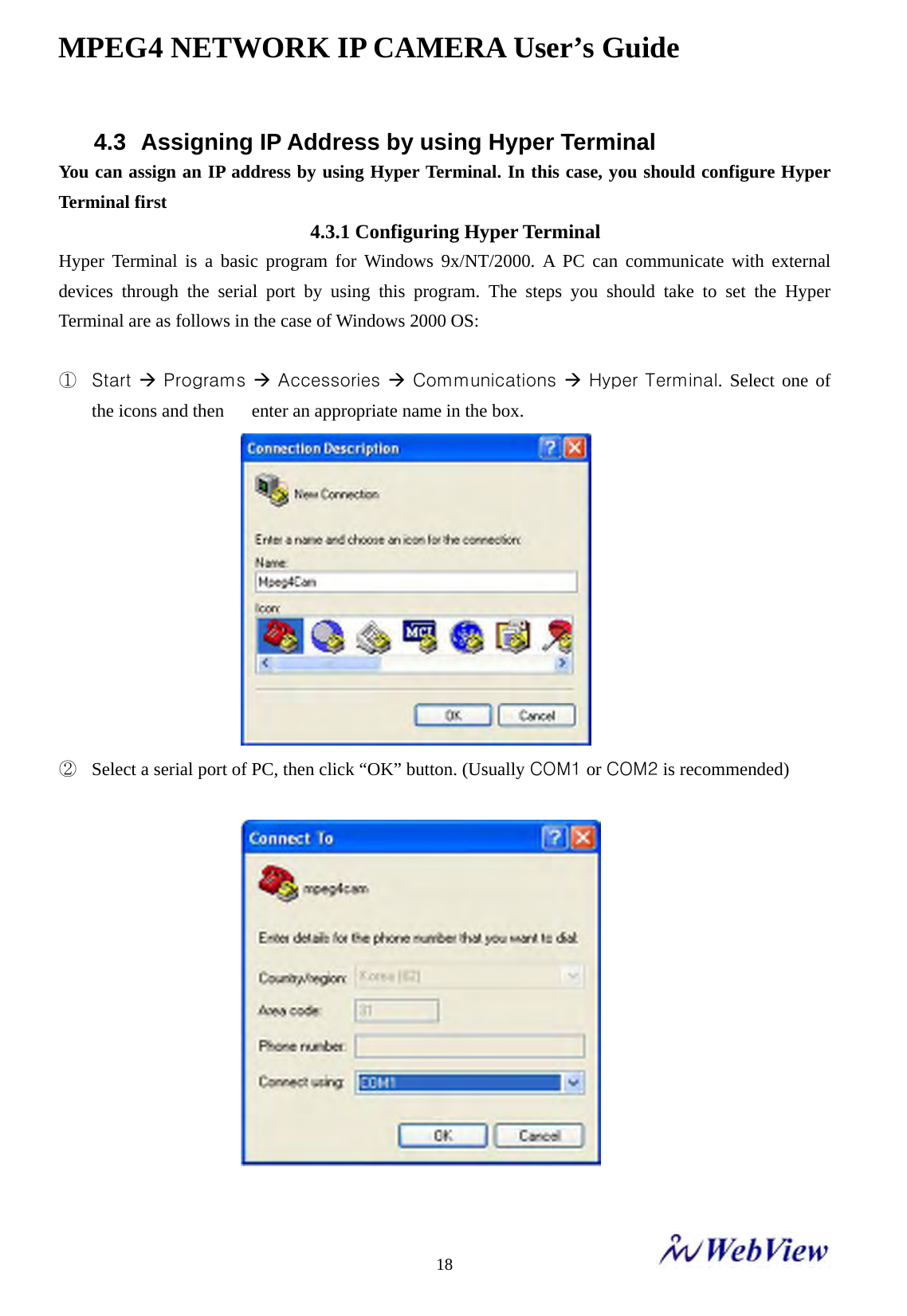
![MPEG4 NETWORK IP CAMERA User’s Guide 21- You can see Network Configuration while [Boot] Prompt is running by pressing ‘ps’ keys again. Here, IP Address, Netmask, gateway, TFTP server, & MAC address (Ethernet address) values are network configuration values. You should change these values in most case. If you don’t know what value you should assign, refer to the network administrator. IP address and subnet mask addresses are separated by colon (:). For example, IP address is represented by decimal numbers delimited by dot (.) like ‘192.168.1.27’. Hexadecimal numbers like ‘ffffff00’ in the case of ‘255.255.255.0’ represents subnet mask address. Note that the numbers of subnet mask value are not delimited by dot. Gateway (g) is the gateway address of Network Camera.](https://usermanual.wiki/MicroWeb/MNC-W200.User-Manual-1/User-Guide-764296-Page-21.png)
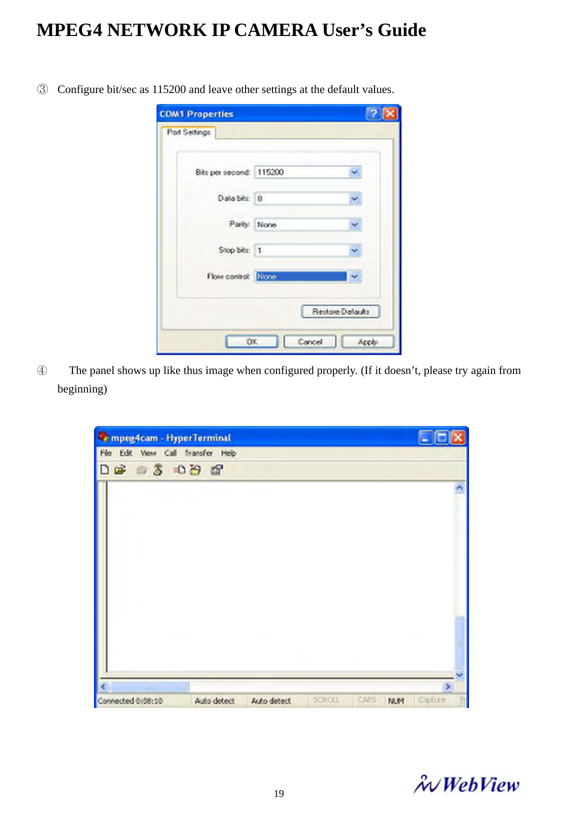
![MPEG4 NETWORK IP CAMERA User’s Guide 22 TFTP Server IP is the address to which Mpeg4 Network IP Camera tries to connect to upgrade its firmware program in flash memory. Mpeg4 Network IP Camera first search this host on the network on booting sequence. For more information on Mpeg4 Network IP Camera upgrade, refer to “E. Updating Mpeg4 Network IP Camera’s newly upgraded Program”. MAC Address is the Ethernet address of Network IP Camera. Type ‘cs’ keys to change the network configuration in [Boot] prompt. If you type ‘cs’ keys, Mpeg4 Network IP Camera shows you the information you can change its values and the current assigned values. You can change as the following figure. - - When you terminate hyper-terminal program after you changed network configuration, hyper-terminal program asks you whether you save the session.](https://usermanual.wiki/MicroWeb/MNC-W200.User-Manual-1/User-Guide-764296-Page-22.png)
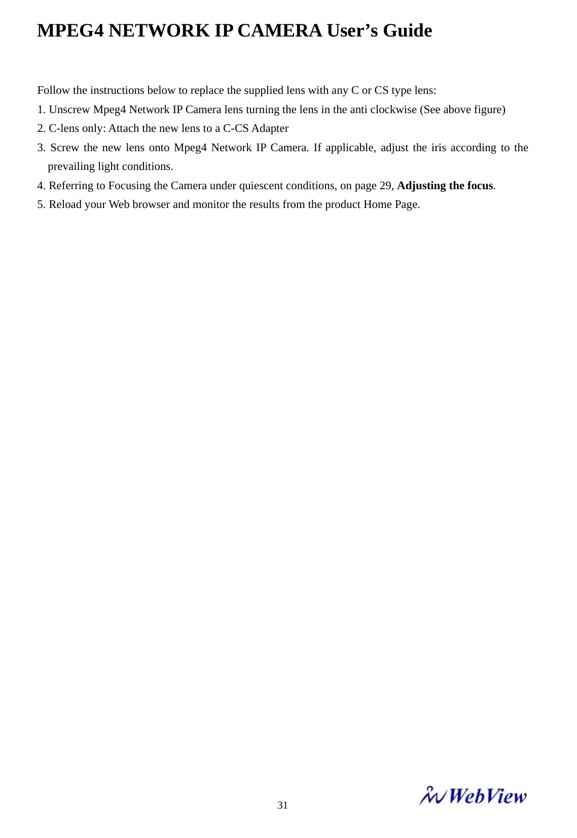
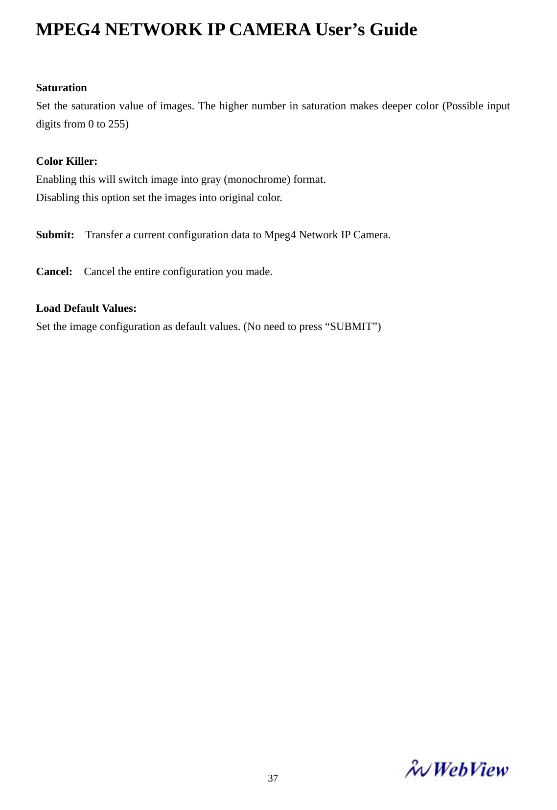
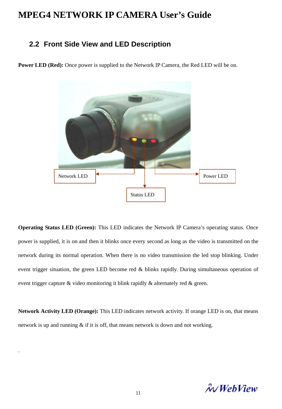
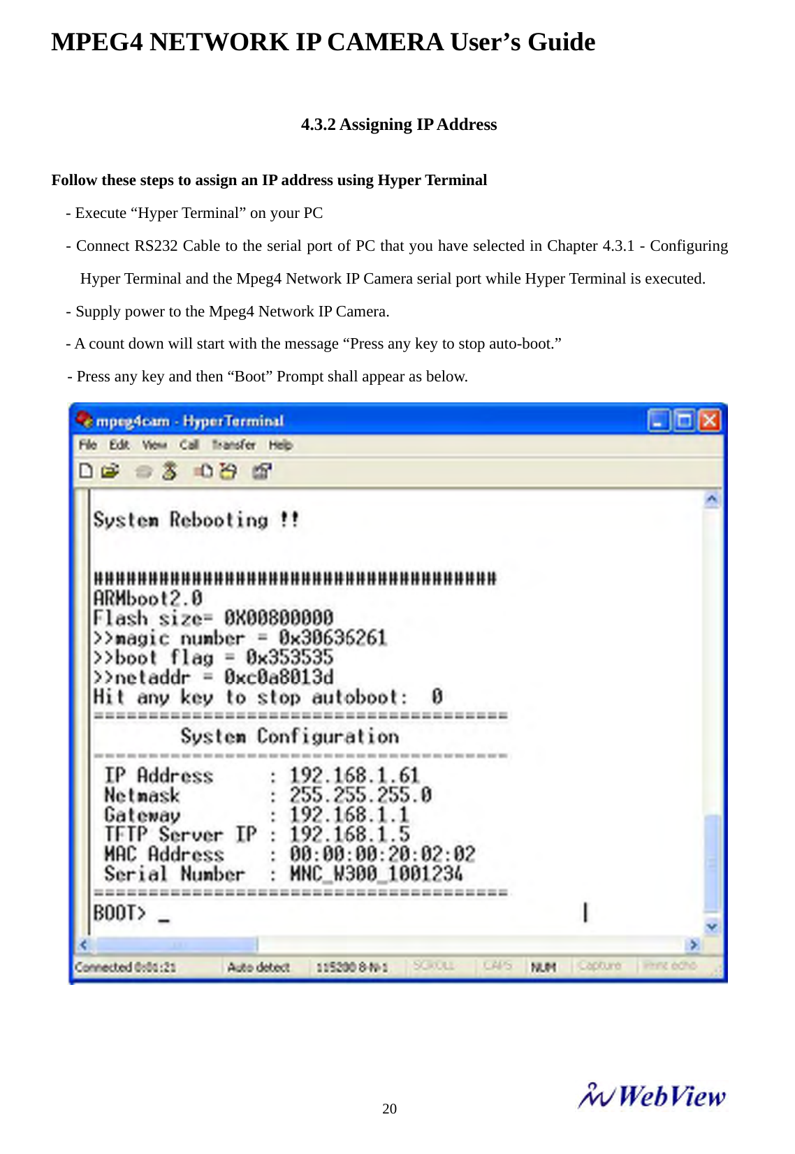
![MPEG4 NETWORK IP CAMERA User’s Guide 346.2 Image Configuration Rate Control Select the Rate control by selecting the VBR [Variable Bit Rate] or CBR [Constant Bit Rate] control. In VBR mode, the picture quality is fixed with fixed quantization value and the bit rate varies automatically in reaction to the complexity of video to maintain the set quality. Thus using the more bandwidth for complex video and less bandwidth for lower activity video. VBR is appropriate for storage applications. VBR can be used where video needs to be streamed over a fixed-bandwidth link. In CBR Mode, the bit rate is fixed irrespective of image complexity, and the picture quality is automatically adjusted by the MPEG4 encoder on a frame-by-frame basis to maintain the pre-set average bit rate. Thus the network bandwidth consumption is always fixed & predictable. CBR is of particular benefit where video needs to be streamed over a fixed-bandwidth link.](https://usermanual.wiki/MicroWeb/MNC-W200.User-Manual-1/User-Guide-764296-Page-34.png)
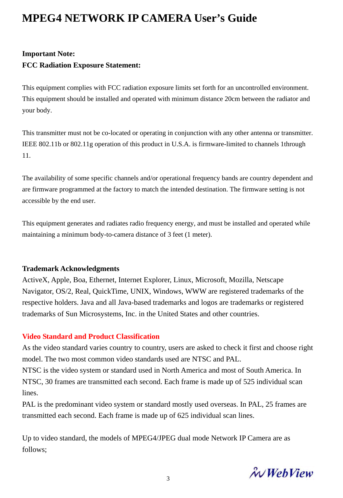
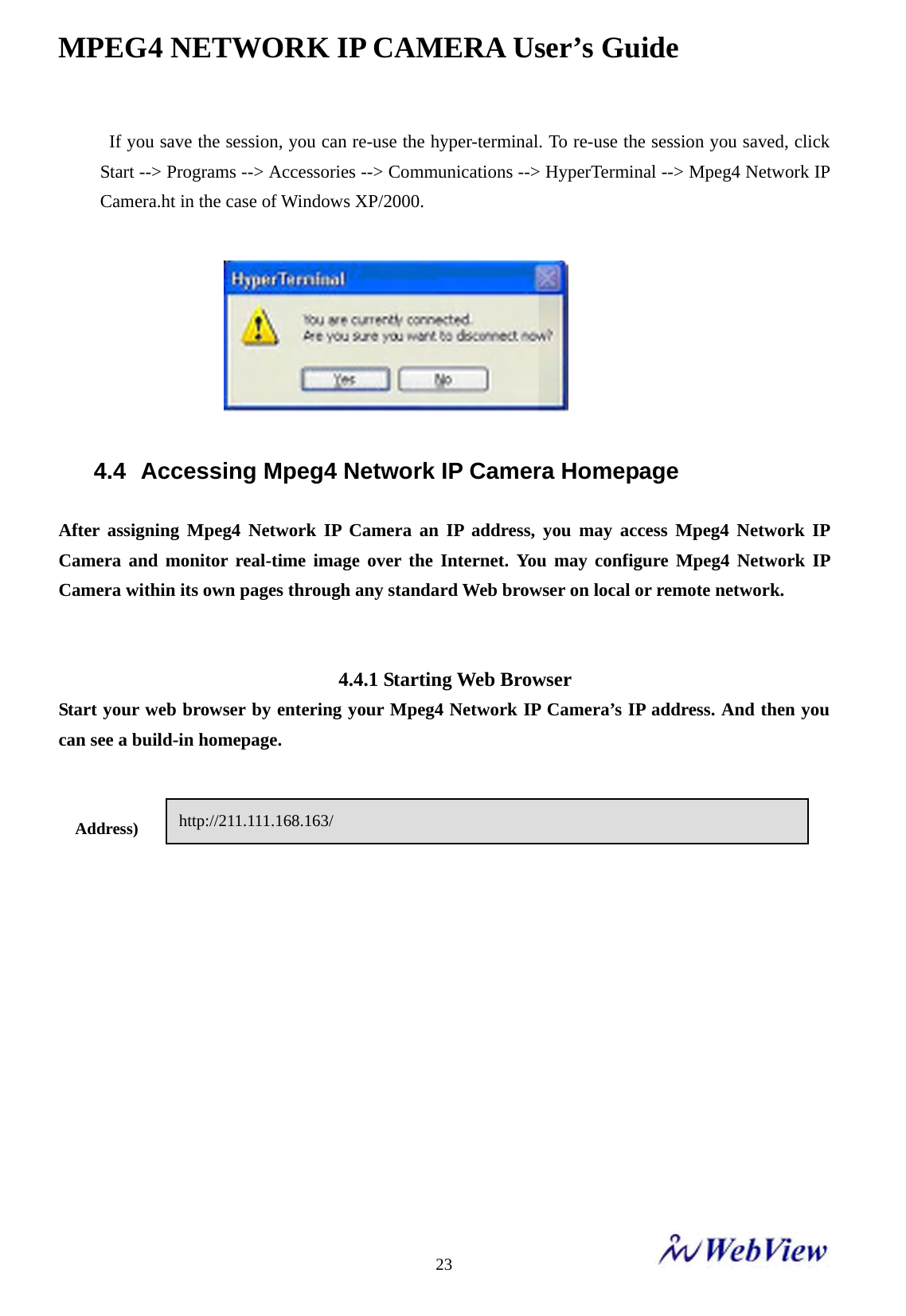
![MPEG4 NETWORK IP CAMERA User’s Guide 35Quality: Set the quality of encoding images. Lower is the number higher is the quality. This option is available when user selects the VBR rate control. Note that to achieve the set quality, the maximum bit rate can be used in VBR mode. Thus, the higher the set quality is, the more bandwidth usage on network. Bit rate: Set the target bit rate of encoding video. This option is available in CBR mode only. You can set the bit rate values from 30 kbps up to 5100 kbps at the interval of 30 kbps. The higher bit rate assures higher quality of live video but on the expense of the more network bandwidth usage. Controlling the maximum bit rate is the good idea for controlling the bandwidth used by Mpeg4 video stream. As the bit rate is fixed, the frame rate and image quality can be affected adversely. That is, the frame rate and image quality are traded off when the bit rate is fixed. Resolution Select the resolution for output video. Mpeg4 network IP camera support two type of image resolution, D1[720x480] & CIF[352x240]. Frame rate: Select frame rate according to the choice. The higher value of frame rate assures smoother video. But the more fps needs the more network-bandwidth. GOP Set the size of GOP (Group of Pictures). MPEG4 video stream consist continuous GOP and one GOP consists of one I frame and P frames. This value equals to the period of I frame. The more GOP size is given the little network-bandwidth will be occupied. Setting high value of GOP will save considerable network bandwidth. Display Name/Location Stamp: Select ‘On’ if you want to display camera name & location on the top of the transmitted images. Display Time/Date Stamp : Select ‘On’ if you want to display the camera time & date on the top of the transmitted images. Brightness Set the image brightness. The higher number means brighter image. (Input digits from 0 to 255) De-Interlace Select this filter if you want to monitor a de-interlaced video (a sequence of frame). The Mpeg4 Network](https://usermanual.wiki/MicroWeb/MNC-W200.User-Manual-1/User-Guide-764296-Page-35.png)