MicroWeb MNC-W200 Network IP Camera User Manual 2
MicroWeb Co., Ltd. Network IP Camera 2
UserManual.wiki
>
MicroWeb
>
MNC-W200 User Manual
>
User Manual 2
Contents
1.
User Manual 1
2.
User Manual 2
User Manual 2
Navigation menu
Upload a User Manual
Namespaces
Wiki Guide
HTML
PDF
Info
Views
User Manual
Discussion / Help
Navigation
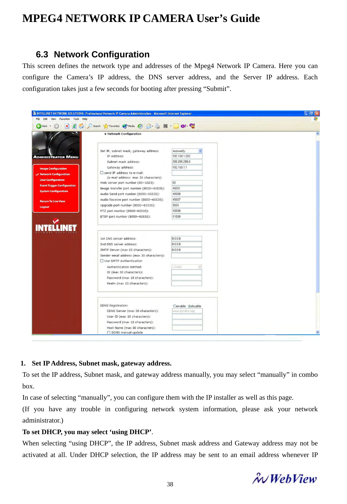
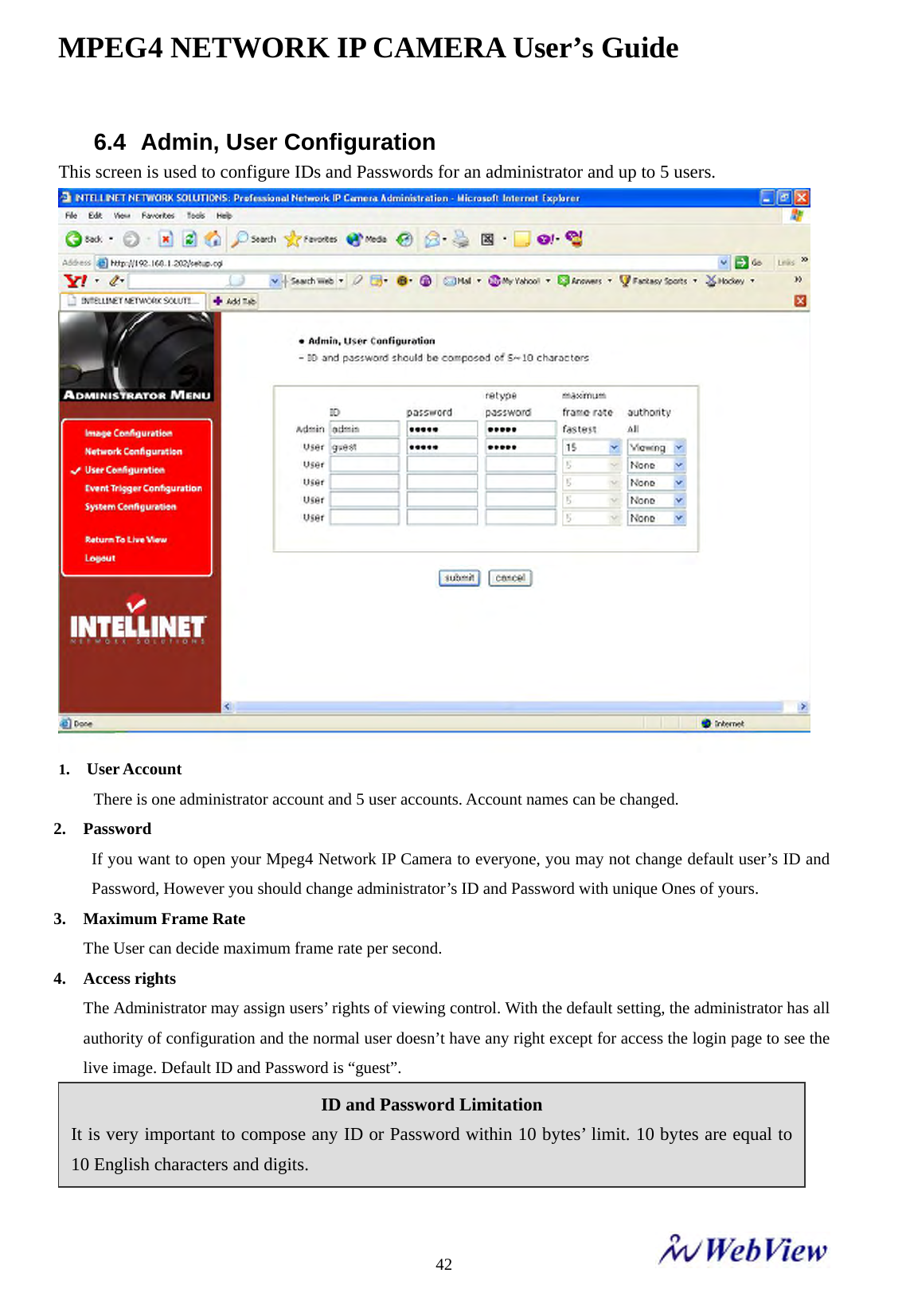
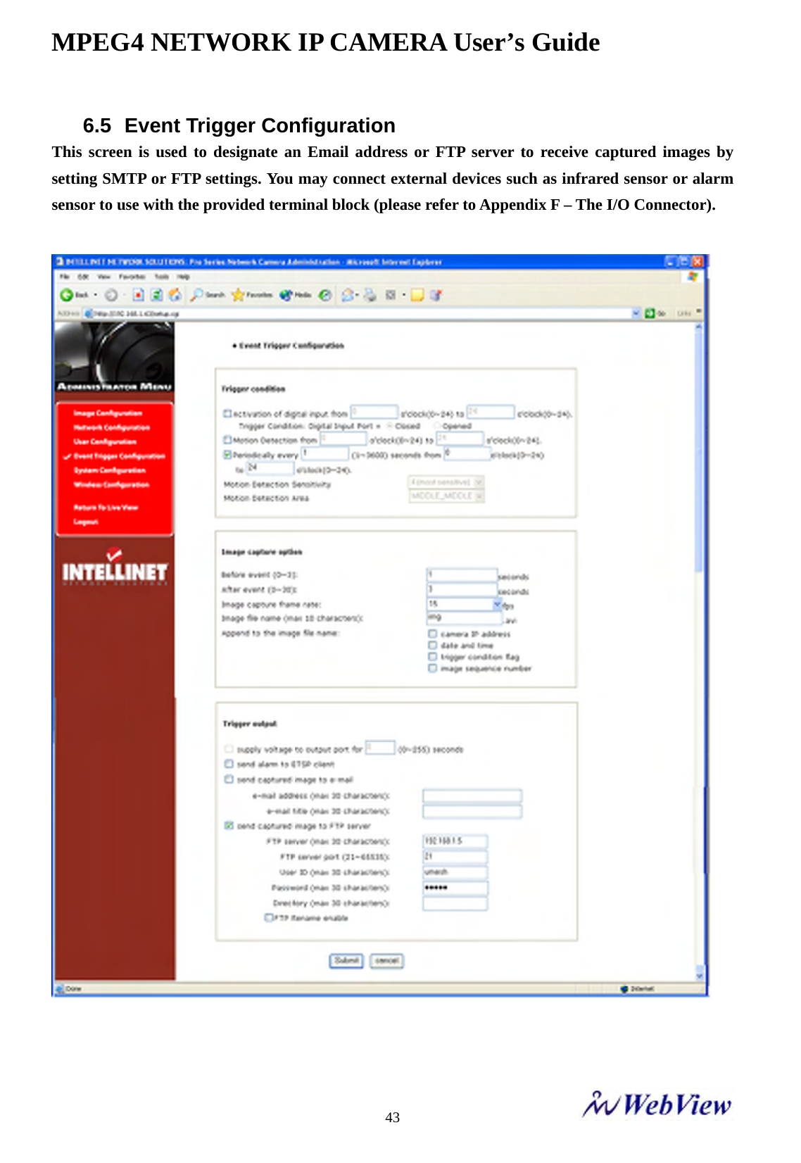
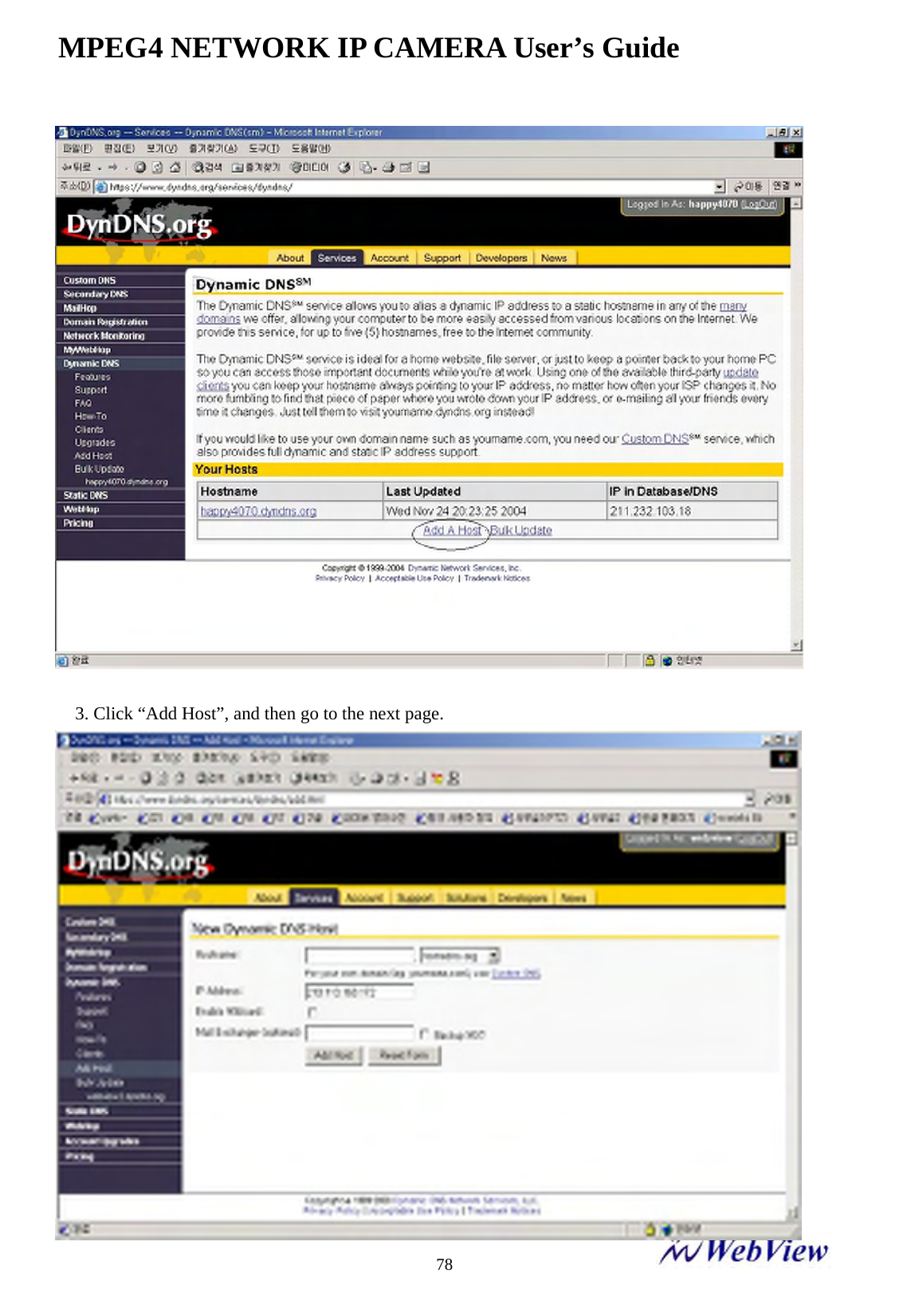
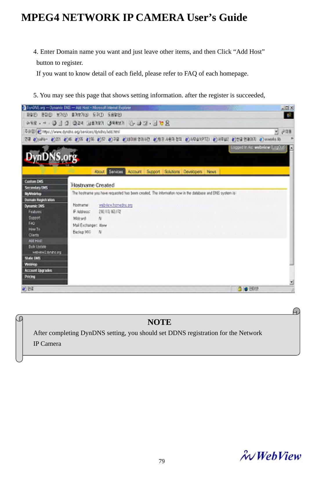
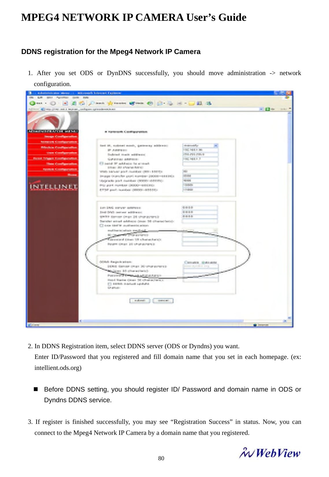
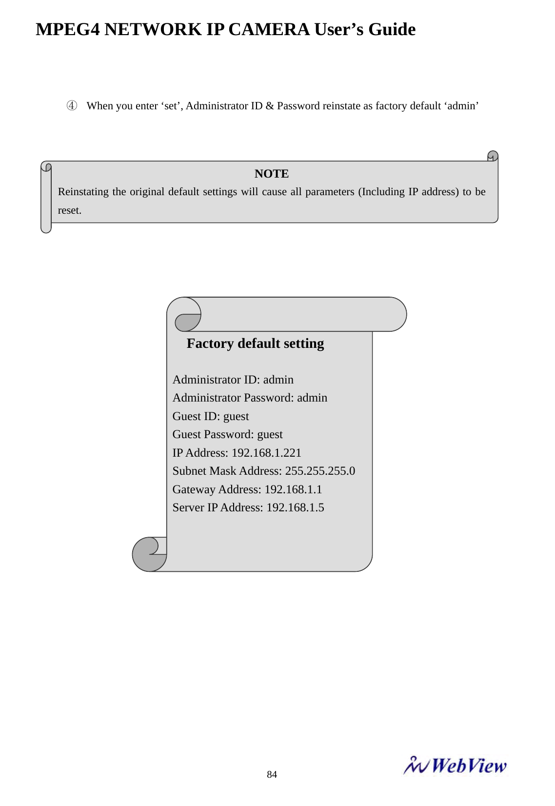
![MPEG4 NETWORK IP CAMERA User’s Guide 83J. Reinstating the Factory Default Settings This information explains instructions in detail on how to set the default settings in the Mpeg4 Network IP Camera. In certain circumstances it may become necessary to restart or reinstate the Factory Default settings for your Mpeg4 Network IP Camera: This is performed by pressing the Reset Button, or using Hyper Terminal Setting. Follow these instructions to reinstate the product factory default settings By pressing Reset button. ① Using a paper clip or any sharp pin, press the reset button on the backside of Mpeg4 Network IP Camera. ② Switch off the Mpeg4 Network IP Camera by disconnecting the power cable. ③ Press and keep the Reset Button pressed, and then reconnect the power supply cable. ④ Keep the Reset Button pressed until the Operating Status LED (Green) blinks three times. (Note that this may take up to 10~15 seconds), then release the button. When the Operating Status LED (Green) blinks three times. By Using Hyper Terminal ① Execute “Hyper Terminal” as referred to Chapter “4.3.1 Configuring Hyper Terminal” ② Supply the power to the Mpeg4 Network IP Camera. ③ After a while, the count down starts with the message “Press Any key tostop auto-boot within 3 seconds...”At this time, press any key. Then,[Mpeg4 Network IP Camera Boot] prompt shows like the below image.](https://usermanual.wiki/MicroWeb/MNC-W200.User-Manual-2/User-Guide-764297-Page-46.png)