Microelectronics Technology BR5811E1 WIRELESS OUTDOOR BRIDGE SYSTEM User Manual BR5811E1 USER S MANUAL
Microelectronics Technology Inc WIRELESS OUTDOOR BRIDGE SYSTEM BR5811E1 USER S MANUAL
Contents
- 1. USERS MANUAL
- 2. HARDWARE INSTALLATION
USERS MANUAL
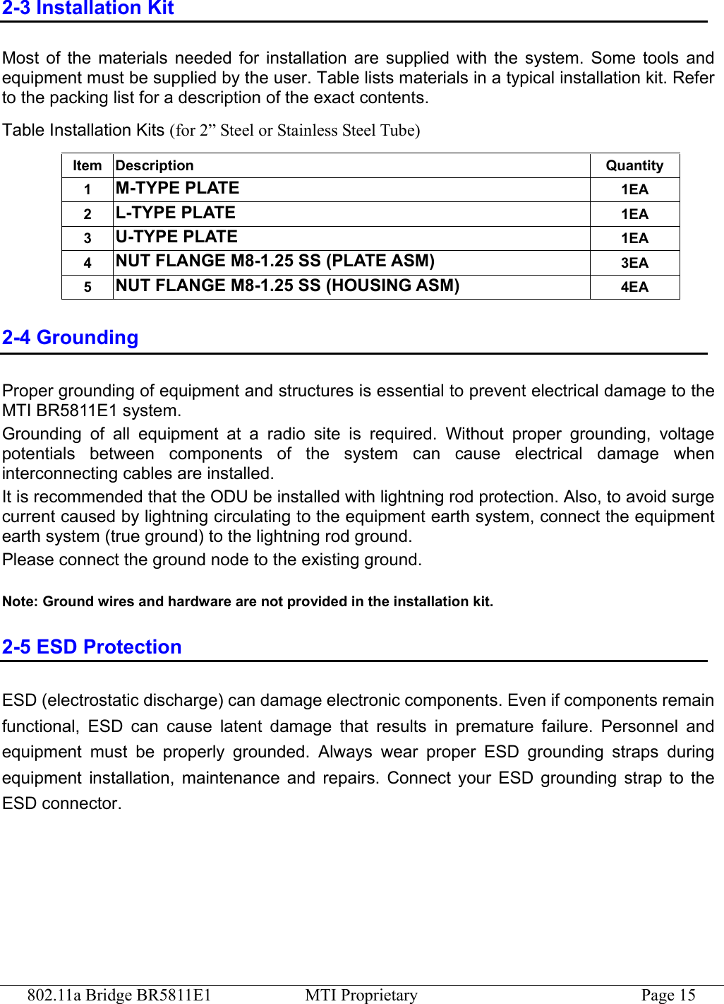
![802.11a Bridge BR5811E1 MTI Proprietary Page 5 Manual Conventions The following conventions are followed in this manual: Bold Bold type within paragraph text indicates commands, file names, directory names, paths, output, or returned values. Italic Within commands, italics indicate a variable that the user must specify. Titles of manuals or other published documents are also set in italics. Courier The courier font indicates output or display. [] Within commands, items enclosed in square brackets are optional parameters or values that the user can choose to specify or omit. {} Within commands, item enclosed in braces are options from which the user must choose. | Within commands, the vertical bar separates options. … An ellipsis indicates a repetition of preceding parameter. > The right angle bracket separates successive menu selection. Notices NOTE: This message denotes neutral or positive information that calls out important points to the text. A note provides information that applies only in special cases. Caution: Cautions call special attention to hazards that can cause system damage or data corruption, to a lesser degree than warnings. Warnings: Warnings call special attention to hazards that can cause system damage, data corruption, personal injury, or death.](https://usermanual.wiki/Microelectronics-Technology/BR5811E1.USERS-MANUAL/User-Guide-386645-Page-5.png)