Microelectronics Technology BR5811E1 WIRELESS OUTDOOR BRIDGE SYSTEM User Manual Chapter 2 Hardware Installation

Microelectronics Technology Inc WIRELESS OUTDOOR BRIDGE SYSTEM Chapter 2 Hardware Installation

Contents

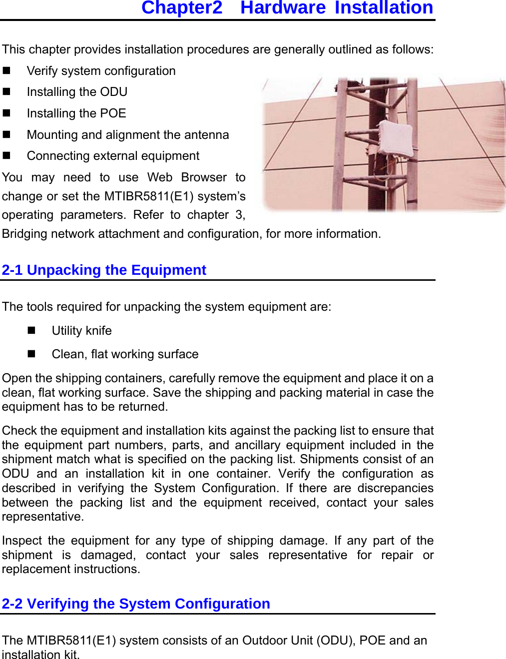
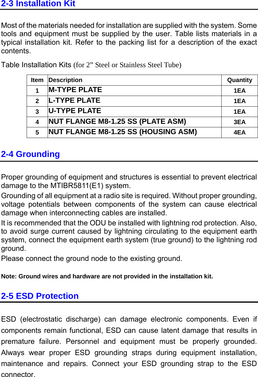
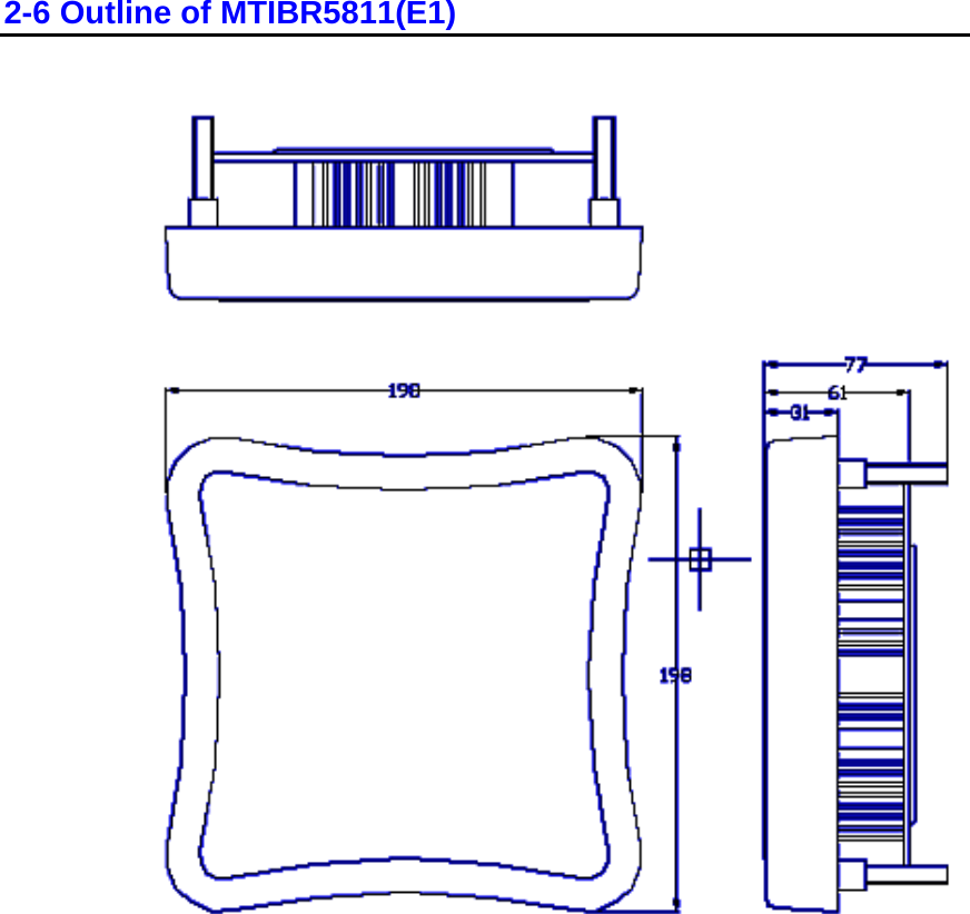
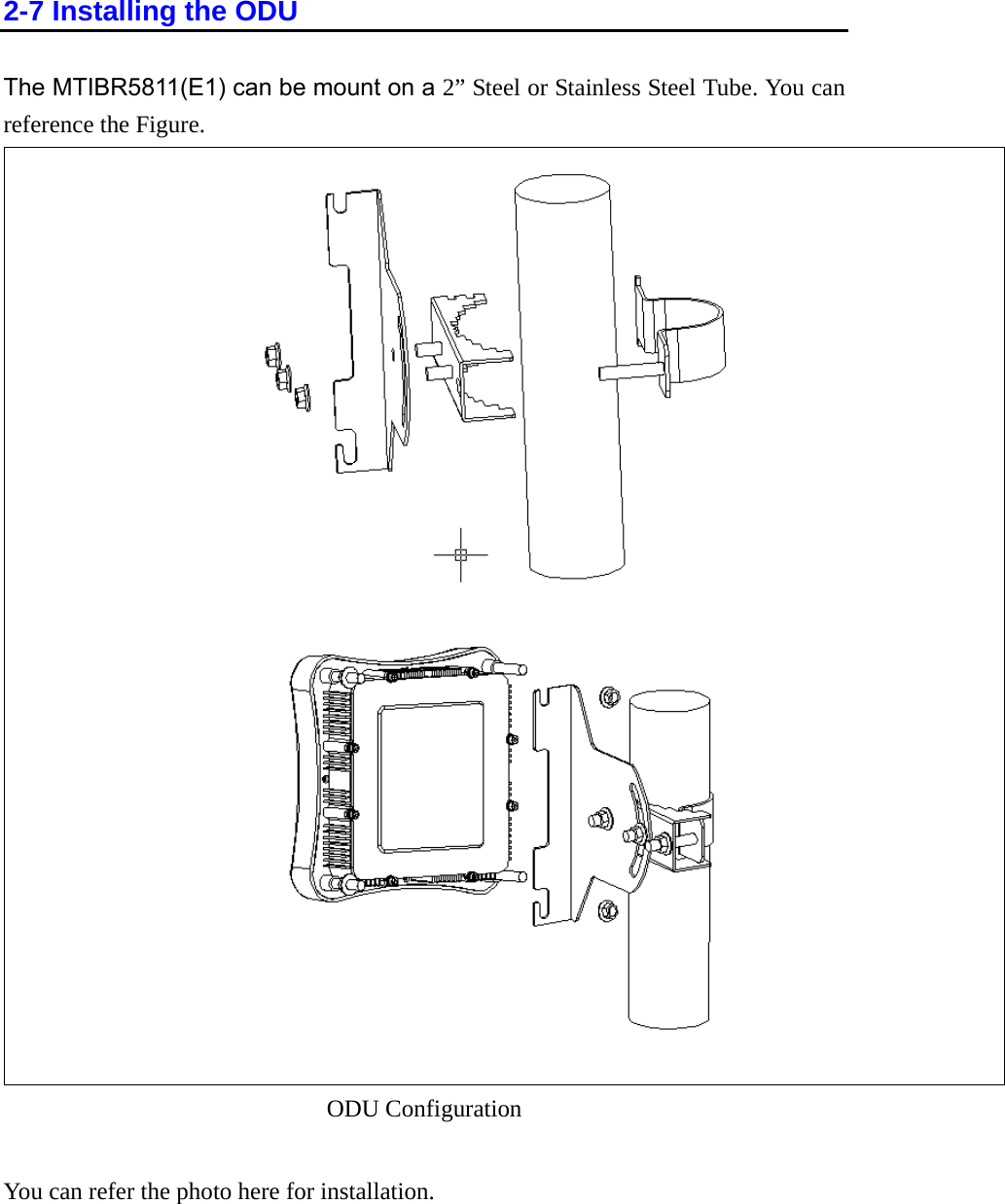
HARDWARE INSTALLATION

Chapter2  Hardware Installation This chapter provides installation procedures are generally outlined as follows:   Verify system configuration   Installing the ODU   Installing the POE   Mounting and alignment the antenna   Connecting external equipment You may need to use Web Browser to change or set the MTIBR5811(E1) system’s operating parameters. Refer to chapter 3, Bridging network attachment and configuration, for more information. 2-1 Unpacking the Equipment The tools required for unpacking the system equipment are:   Utility knife   Clean, flat working surface Open the shipping containers, carefully remove the equipment and place it on a clean, flat working surface. Save the shipping and packing material in case the equipment has to be returned. Check the equipment and installation kits against the packing list to ensure that the equipment part numbers, parts, and ancillary equipment included in the shipment match what is specified on the packing list. Shipments consist of an ODU and an installation kit in one container. Verify the configuration as described in verifying the System Configuration. If there are discrepancies between the packing list and the equipment received, contact your sales representative. Inspect the equipment for any type of shipping damage. If any part of the shipment is damaged, contact your sales representative for repair or replacement instructions. 2-2 Verifying the System Configuration The MTIBR5811(E1) system consists of an Outdoor Unit (ODU), POE and an installation kit.
2-3 Installation Kit Most of the materials needed for installation are supplied with the system. Some tools and equipment must be supplied by the user. Table lists materials in a typical installation kit. Refer to the packing list for a description of the exact contents. Table Installation Kits (for 2” Steel or Stainless Steel Tube) Item Description  Quantity 1  M-TYPE PLATE 1EA 2  L-TYPE PLATE 1EA 3  U-TYPE PLATE 1EA 4  NUT FLANGE M8-1.25 SS (PLATE ASM) 3EA 5  NUT FLANGE M8-1.25 SS (HOUSING ASM) 4EA 2-4 Grounding Proper grounding of equipment and structures is essential to prevent electrical damage to the MTIBR5811(E1) system. Grounding of all equipment at a radio site is required. Without proper grounding, voltage potentials between components of the system can cause electrical damage when interconnecting cables are installed. It is recommended that the ODU be installed with lightning rod protection. Also, to avoid surge current caused by lightning circulating to the equipment earth system, connect the equipment earth system (true ground) to the lightning rod ground. Please connect the ground node to the existing ground.  Note: Ground wires and hardware are not provided in the installation kit. 2-5 ESD Protection ESD (electrostatic discharge) can damage electronic components. Even if components remain functional, ESD can cause latent damage that results in premature failure. Personnel and equipment must be properly grounded. Always wear proper ESD grounding straps during equipment installation, maintenance and repairs. Connect your ESD grounding strap to the ESD connector.
2-6 Outline of MTIBR5811(E1)
2-7 Installing the ODU The MTIBR5811(E1) can be mount on a 2” Steel or Stainless Steel Tube. You can reference the Figure.     guration You can refer the photo here for installation. ODU Confi
2-8 Connecting the cable An power to the ODU and allows Ethernet data to flow between Stations with Bridge C power is 2-9 Align the Antenna (TBD) Ethernet cable connects the ODU to the POE output port. The cable connects system. Another Ethernet cable connects the station to POE input port. Aapplied to the bridge system by connect it to POE AC adapter.   Notices The RSSI BNC connector is still not function well now. Please use the RSSI reading from the statistics window in WEB -base browser.  Antenna alignment is performed with both the near-end and the far-end ile monitoring the RSSI  alignment v her the RSSI voltage reading is, the  voltage reading is from 0 to 3.28VDC, e resolution is 256 ns. sure optimum   performance, the main lobe of the antenna must be aligned  the antenna through the range of radiated power n be positively identified. Each side lobe is approximately 20 dB lower than be as you move away from the main lobe.  men dure is applicable to both protected and otions. Align the antenna as follows: ced tial alignment does not produce the correct ng. sult your path ca n and adjust the radio’s attenuation level, so do eed the maxidg  far end is operational.    Bri ve the protective cap from the RSSI BNC connector. 4.  Connect a voltmeter to the RSSI connector and set the voltmeter to measure VDC. uth direction. Monitor the voltmeter and locate the position where the voltage is minimum (null) and record the ot the antenna in the elevation direction. Pivot ltage is minimum on the voltmeter terminals operating. The antenna position is adjusted whfor antennastronger the signal. The range of the RSSIoltage. The higand th  divisioCaution: To en systemwith the center of the far end antenna. Rotateso the main lobe cathe preceding loThis antenna align t procenon-protected system c nfiguraNote: Repeat this pro ure if the iniRSSI readi1.  Con lculationot exc imum receiving signal level.   2.    Verify that the Br e at the3.  At the near-end dge, remo5.  Pivot the antenna slowly in the azimreading. 6.  Monitor the voltmeter and pivthe antenna to the position where the voand record the reading.
7.  Repeat these steps as necessary to get an accurate reading. 8.  Tighten all fasteners and check that the null has not changed. If the null has changed, repeat the procedure until the null is maintained after tightening the fasteners. 9.  Disconnect the voltmeter and replace the RSSI protective cap.   Note: The signal level over the link is not optimal until both antennas are correctly aligned. 2-10 External Antenna    For BR5811(E) If you use the external antenna option, you can follow the antenna installation guide to fixed the antenna and use the RF cable in the installation kit to connect the Bridge and antenna. External antenna Specifications: KBNT5826-13 5.8GHz WLAN 26 Grid Parabolic Antenna Frequency: 5725-5875MHz Gain: 26 dBi Impedance: 50 . Beam width:  H6 V8 Polarization: Linear, Vertical Front to Back Ratio:  > 30 dB Maximum Input Power:  200W Lightning Protection:  DC Ground Connector:  N type female VSWR   1.4 Dimension:  Caliber 520 x 450 mm, 2.6kgw Rated Wind Velocity:  60 m/s Mounting Hardware:  Φ30-Φ60

Navigation menu