Microelectronics Technology RU-824 RFID UHF USB READER User Manual CCCCCCCCCCCC
Microelectronics Technology Inc RFID UHF USB READER CCCCCCCCCCCC
UserManual.wiki
>
Microelectronics Technology
>
RU 824 User Manual
user manual
Navigation menu
Upload a User Manual
Namespaces
Wiki Guide
HTML
PDF
Info
Views
User Manual
Discussion / Help
Navigation
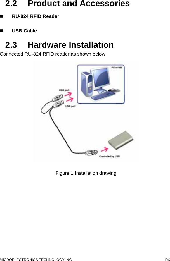
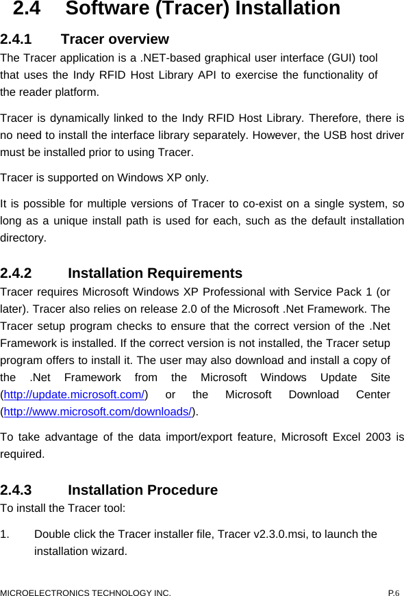
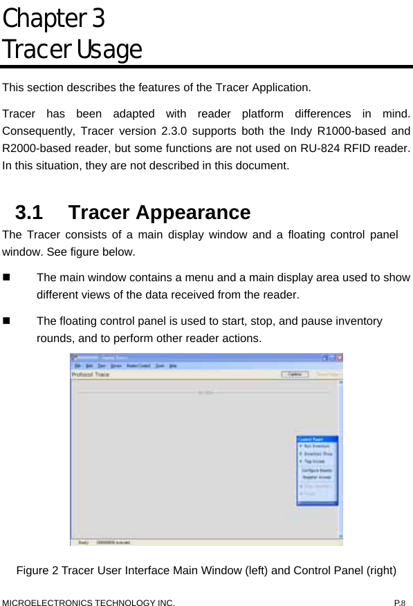
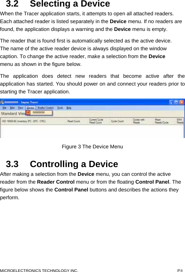
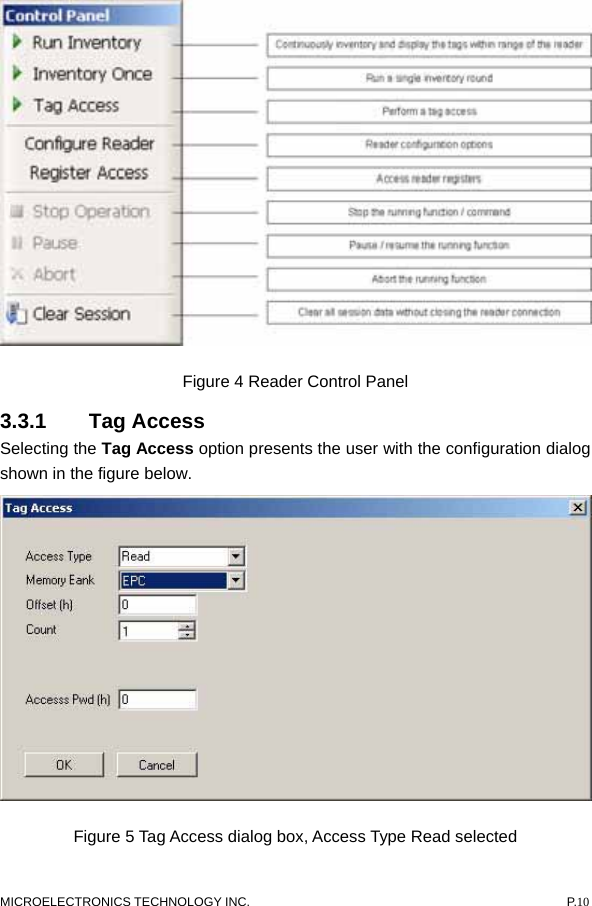
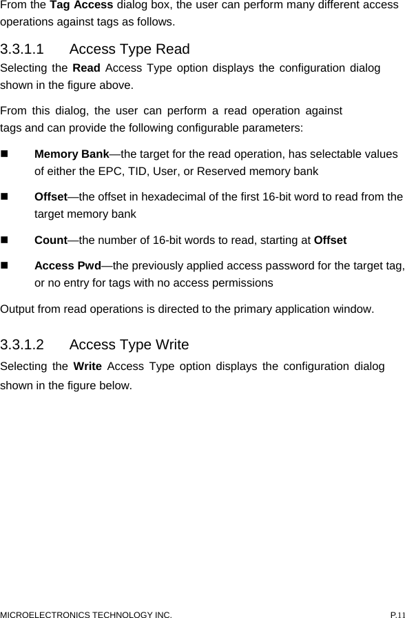
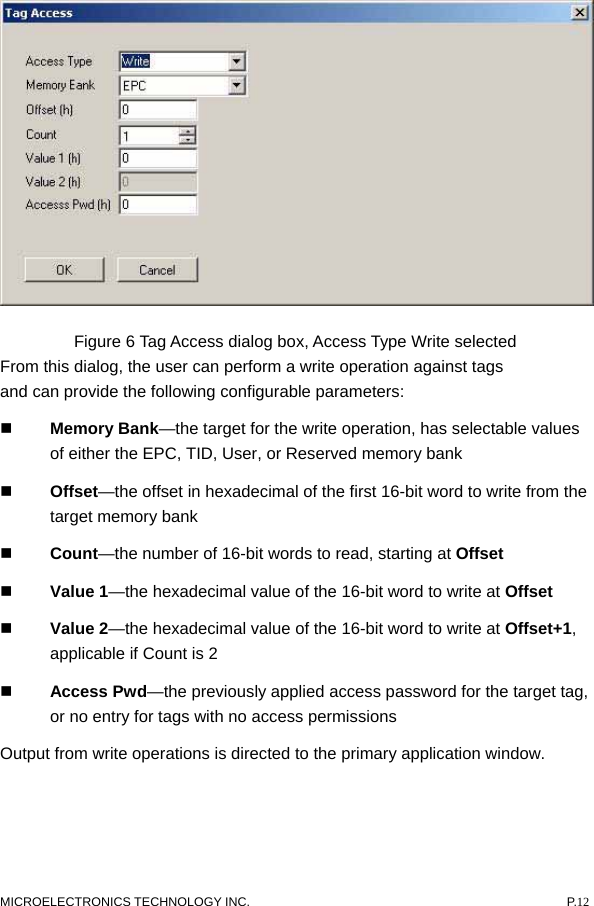
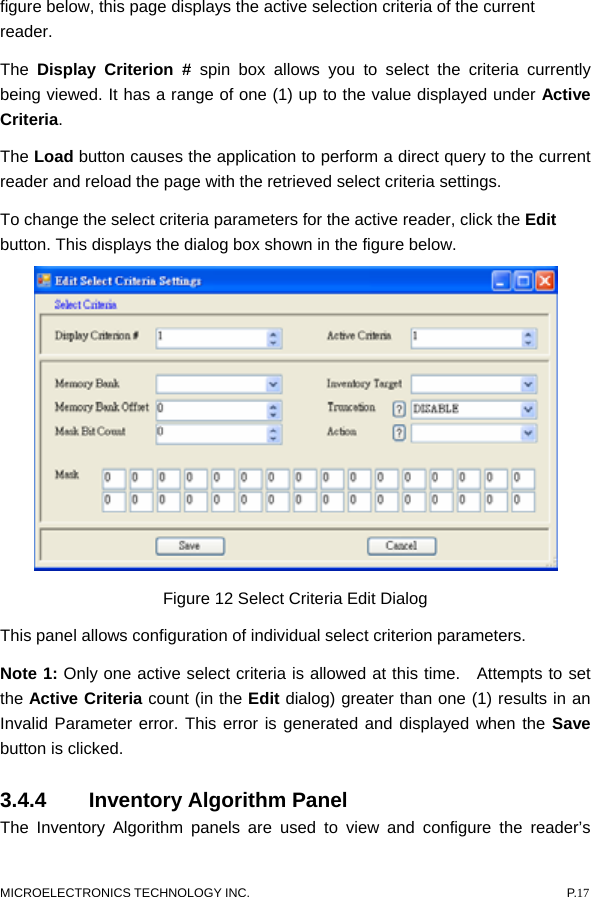
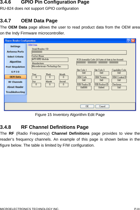
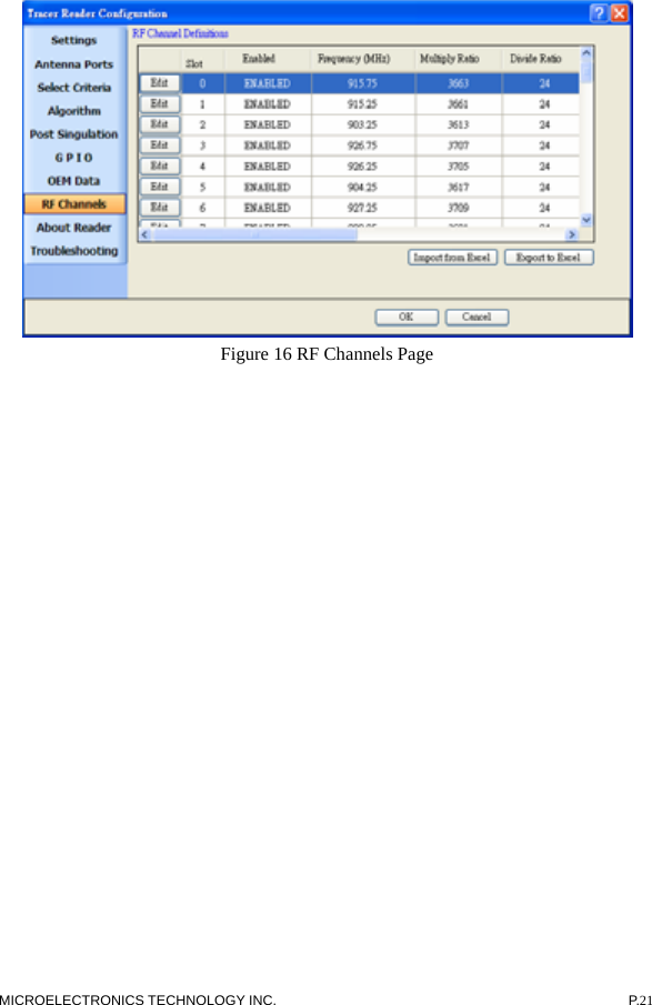
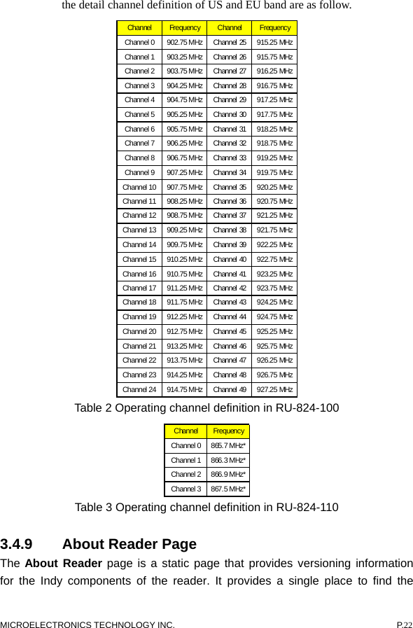
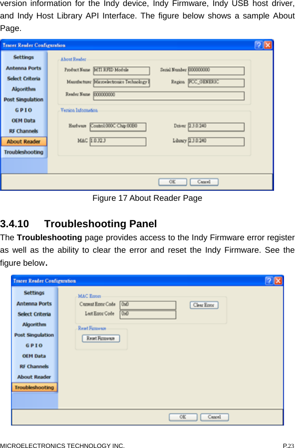
![MICROELECTRONICS TECHNOLOGY INC. P.7 2. When prompted, designate the desired installation directory. The default is [Program Files]\IMPINJ\Tracer v2.3.0\. 3. Installation includes the C++ runtime libraries and adds a desktop shortcut to the Tracer application. 1. To Start the Tracer application: Double click the desktop shortcut, or Use the Start Menu. For example, if installed to the default directory: Click Start, Select All Programs, IMPINJ, Impinj Tracer v2.3.0, Click Tracer. Open the Tracer installation folder and double click Tracer.exe 2.4.4 Removal Procedure To uninstall the Tracer tool: 1. Click Start, Select All Programs, IMPINJ, Impinj Tracer v2.3.0, Click Uninstall Tracer. When prompted to uninstall this product, click Yes. Alternatively: 1. Open the Control Panel and select Add or Remove Programs. 2. Select the entry for the Tracer version to uninstall and click Change/Remove. 3. When prompted to remove this product, click Yes.](https://usermanual.wiki/Microelectronics-Technology/RU-824/User-Guide-1378709-Page-7.png)