Microelectronics Technology RU-824 RFID UHF USB READER User Manual CCCCCCCCCCCC
Microelectronics Technology Inc RFID UHF USB READER CCCCCCCCCCCC
user manual

MTI RU-824 RFID Reader
Quick Guide
Version 1.1
MTI Group Proprietary Information
Any unauthorized use, duplication, reproduction, or disclosure of this
document may be considered as infringement of MTI Group’s intellectual
property rights, the infringer may be accused and liable applicable legal
penalties.
MICROELECTRONICS TECHNOLOGY INC. P.2
Chapter 1 Introduction........................................................... 3
1.1 Purpose................................................................ 3
1.2 Trademarks .......................................................... 3
Chapter 2 Product Introduction............................................. 4
2.1 Product Specification ........................................... 4
2.2 Product and Accessories ..................................... 5
2.3 Hardware Installation ........................................... 5
2.4 Software (Tracer) Installation............................... 6
2.4.1 Tracer overview....................................... 6
2.4.2 Installation Requirements ....................... 6
2.4.3 Installation Procedure ............................. 6
2.4.4 Removal Procedure ................................ 7
Chapter 3 Tracer Usage ....................................................... 8
3.1 Tracer Appearance .............................................. 8
3.2 Selecting a Device ............................................... 9
3.3 Controlling a Device............................................. 9
3.3.1 Tag Access ........................................... 10
3.4 Configure Reader............................................... 14
3.4.1 Settings Page........................................ 16
3.4.2 Antenna Configuration Page................. 16
3.4.3 Select Criteria Page .............................. 16
3.4.4 Inventory Algorithm Panel..................... 17
3.4.5 Post Singulation Criteria Page.............. 19
3.4.6 GPIO Pin Configuration Page............... 20
3.4.7 OEM Data Page.................................... 20
3.4.8 RF Channel Definitions Page................ 20
3.4.9 About Reader Page............................... 22
3.4.10 Troubleshooting Panel .......................... 23

MICROELECTRONICS TECHNOLOGY INC. P.3
Chapter 1
Introduction
1.1 Purpose
This guide will help you set-up and configure your RU-824 RFID reader.
Following the installation instructions should be quick and easy.
1.2 Configuration
This guide covers the following configuration
Configuration Part number
US band RFID Reader RU-824-100
EU band RFID Reader RU-824-110
1.3 Trademarks
The product described in this guide is a licensed product of
Microelectronics Technology Inc.
Microsoft, Windows 95, Windows 98, Windows Millennium Edition,
Windows NT, Windows 2000, Windows XP, and MS-DOS are registered
trademarks of the Microsoft Corporation.
Java is a trademark of Sun Microsystems, Inc.
Impinj is a trademark of Impinj Corporation.
All other brand and product names are trademarks or registered
trademarks of their respective owners.

MICROELECTRONICS TECHNOLOGY INC. P.4
Chapter 2
Product Introduction
2.1 Product Specification
Module Number RU-824
Features
•Compliant with EPCglobal C1G2 / ISO 18000-6C
• Adjustable Output Power
• Low Power Consumption
• FCC & ETSI Certification
• Compact dimensions
• Maximum tag read distance of 1 m
Air-interface Protocols EPC Class 1 Gen 2/ISO 18000-6C
Frequency Band US: 902~928MHz ; EU: 865~868MHz
Output Power Adjustable +5 ~ +24dBm in 1dB step
Supply Voltage Powered by USB
Current Consumption Idle mode:0.25A
Scan mode: Max 1A@ 24dBm
Host Communication
Interfaces / Data Rates USB 2.0 Full Speed: 12 Mb/s
Compliance
US: FCC 47 CFR Part 15, Subpart C (section 15.247), Subpart B, SAR
OET 65,
EU: ETSI EN 302 208-1 V1.2.1,EN 301 489-1/-3, EN 60950-1,
SAR EN 62311
Effective Range Max. 1m with build-in antenna
Physical 80 mm L x 57 mm W x 14 mm H
Antenna Build-in linear polarization antenna
Environment Storage Temperature: -40°C to 85°C
Operating Temperature: 0°C to 40°C
Table 1 RU-824 Specification
2.2 Product and Accessories
RU-824 RFID Reader
USB Cable
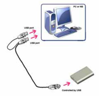
2.3 Hardware Installation
Connected RU-824 RFID reader as shown below
Figure 1 Installation drawing
MICROELECTRONICS TECHNOLOGY INC. P.5

MICROELECTRONICS TECHNOLOGY INC. P.6
2.4 Software (Tracer) Installation
2.4.1 Tracer overview
The Tracer application is a .NET-based graphical user interface (GUI) tool
that uses the Indy RFID Host Library API to exercise the functionality of
the reader platform.
Tracer is dynamically linked to the Indy RFID Host Library. Therefore, there is
no need to install the interface library separately. However, the USB host driver
must be installed prior to using Tracer.
Tracer is supported on Windows XP only.
It is possible for multiple versions of Tracer to co-exist on a single system, so
long as a unique install path is used for each, such as the default installation
directory.
2.4.2 Installation Requirements
Tracer requires Microsoft Windows XP Professional with Service Pack 1 (or
later). Tracer also relies on release 2.0 of the Microsoft .Net Framework. The
Tracer setup program checks to ensure that the correct version of the .Net
Framework is installed. If the correct version is not installed, the Tracer setup
program offers to install it. The user may also download and install a copy of
the .Net Framework from the Microsoft Windows Update Site
(http://update.microsoft.com/) or the Microsoft Download Center
(http://www.microsoft.com/downloads/).
To take advantage of the data import/export feature, Microsoft Excel 2003 is
required.
2.4.3 Installation Procedure
To install the Tracer tool:
1. Double click the Tracer installer file, Tracer v2.3.0.msi, to launch the
installation wizard.
MICROELECTRONICS TECHNOLOGY INC. P.7
2. When prompted, designate the desired installation directory. The default
is [Program Files]\IMPINJ\Tracer v2.3.0\.
3. Installation includes the C++ runtime libraries and adds a desktop
shortcut to the Tracer application.
1. To Start the Tracer application:
Double click the desktop shortcut, or
Use the Start Menu. For example, if installed to the default
directory: Click Start, Select All Programs, IMPINJ, Impinj Tracer
v2.3.0, Click Tracer.
Open the Tracer installation folder and double click Tracer.exe
2.4.4 Removal Procedure
To uninstall the Tracer tool:
1. Click Start, Select All Programs, IMPINJ, Impinj Tracer v2.3.0, Click
Uninstall Tracer. When prompted to uninstall this product, click Yes.
Alternatively:
1. Open the Control Panel and select Add or Remove Programs.
2. Select the entry for the Tracer version to uninstall and click
Change/Remove.
3. When prompted to remove this product, click Yes.
Chapter 3
Tracer Usage
This section describes the features of the Tracer Application.
Tracer has been adapted with reader platform differences in mind.
Consequently, Tracer version 2.3.0 supports both the Indy R1000-based and
R2000-based reader, but some functions are not used on RU-824 RFID reader.
In this situation, they are not described in this document.
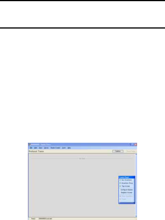
3.1 Tracer Appearance
The Tracer consists of a main display window and a floating control panel
window. See figure below.
The main window contains a menu and a main display area used to show
different views of the data received from the reader.
The floating control panel is used to start, stop, and pause inventory
rounds, and to perform other reader actions.
Figure 2 Tracer User Interface Main Window (left) and Control Panel (right)
MICROELECTRONICS TECHNOLOGY INC. P.8
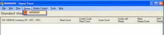
3.2 Selecting a Device
When the Tracer application starts, it attempts to open all attached readers.
Each attached reader is listed separately in the Device menu. If no readers are
found, the application displays a warning and the Device menu is empty.
The reader that is found first is automatically selected as the active device.
The name of the active reader device is always displayed on the window
caption. To change the active reader, make a selection from the Device
menu as shown in the figure below.
The application does detect new readers that become active after the
application has started. You should power on and connect your readers prior to
starting the Tracer application.
Figure 3 The Device Menu
3.3 Controlling a Device
After making a selection from the Device menu, you can control the active
reader from the Reader Control menu or from the floating Control Panel. The
figure below shows the Control Panel buttons and describes the actions they
perform.
MICROELECTRONICS TECHNOLOGY INC. P.9
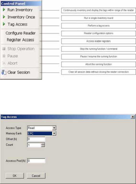
Figure 4 Reader Control Panel
3.3.1 Tag Access
Selecting the Tag Access option presents the user with the configuration dialog
shown in the figure below.
Figure 5 Tag Access dialog box, Access Type Read selected
MICROELECTRONICS TECHNOLOGY INC. P.10
MICROELECTRONICS TECHNOLOGY INC. P.11
From the Tag Access dialog box, the user can perform many different access
operations against tags as follows.
3.3.1.1 Access Type Read
Selecting the Read Access Type option displays the configuration dialog
shown in the figure above.
From this dialog, the user can perform a read operation against
tags and can provide the following configurable parameters:
Memory Bank—the target for the read operation, has selectable values
of either the EPC, TID, User, or Reserved memory bank
Offset—the offset in hexadecimal of the first 16-bit word to read from the
target memory bank
Count—the number of 16-bit words to read, starting at Offset
Access Pwd—the previously applied access password for the target tag,
or no entry for tags with no access permissions
Output from read operations is directed to the primary application window.
3.3.1.2 Access Type Write
Selecting the Write Access Type option displays the configuration dialog
shown in the figure below.
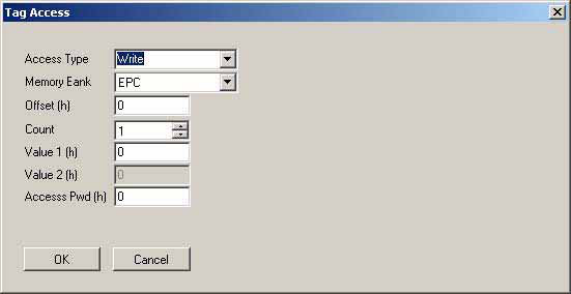
Figure 6 Tag Access dialog box, Access Type Write selected
From this dialog, the user can perform a write operation against tags
and can provide the following configurable parameters:
Memory Bank—the target for the write operation, has selectable values
of either the EPC, TID, User, or Reserved memory bank
Offset—the offset in hexadecimal of the first 16-bit word to write from the
target memory bank
Count—the number of 16-bit words to read, starting at Offset
Value 1—the hexadecimal value of the 16-bit word to write at Offset
Value 2—the hexadecimal value of the 16-bit word to write at Offset+1,
applicable if Count is 2
Access Pwd—the previously applied access password for the target tag,
or no entry for tags with no access permissions
Output from write operations is directed to the primary application window.
MICROELECTRONICS TECHNOLOGY INC. P.12
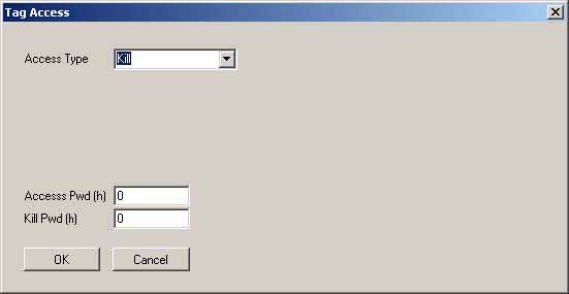
3.3.1.3 Access Type Kill
The kill operation allows the user to render any tag with a matching access and
kill password as permanently non-functional. Selecting the Kill Access Type
option displays the configuration dialog shown in the figure below.
Figure 7 Tag Access dialog box, Access Type Kill selected
Note: Tags with a value of zero for their password are not expected
to respond to the kill command.
3.3.1.4 Access Type Lock
The lock operation allows the user to specify the desired exposure of tag kill and
access password permissions. It also allows the user to specify write permission
and condition levels for the EPC, TID, and User memory banks. Selecting the
Lock Access Type option displays the dialog box shown in the figure below.
MICROELECTRONICS TECHNOLOGY INC. P.13
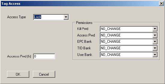
Figure 8 Tag Access dialog box, Access Type Lock selected
Note that all permissions are set in a single operation. In many circumstances, it
may be desirable to leave one or more of the target passwords or permissions
in an unmodified state. To do this, select the NO_CHANGE option for those
targets.
3.4 Configure Reader
The Tracer application allows the user to configure many of the settings of the
attached readers. To access the configuration panel:
Note: This is a quick guide for RU-824 RFID reader. Some functions are not
described and released in this document.
From the Reader Control menu, select Configure Reader. Alternatively, from
the Control Panel, select Configure Reader. See the figure below. This
opens the Tracer Reader Configuration dialog box.
MICROELECTRONICS TECHNOLOGY INC. P.14
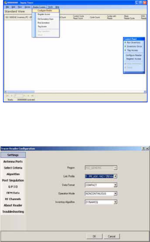
Figure 9 Accessing Reader Configuration
The Tracer Reader Configuration dialog contains many function-specific
pages, each of which is listed on the left-hand side selection bar. The current
selection is always indicated by a visual highlight. For example, in the figure
below, the Settings page is active.
Figure 10 Reader Configuration Dialog Box
MICROELECTRONICS TECHNOLOGY INC. P.15
3.4.1 Settings Page
When the Reader Configuration dialog first opens, it displays the Settings
page shown in the figure above. The settings displayed are the current
settings on the reader.
From this page, you can view and/or configure the following items:
Operating Region (Read only, set within the reader)
Link Profile
Data Format (Compact, Normal or Extended)
Operational Mode (Continuous Mode or Discontinuous Mode)
Inventory Algorithm (Fixed Q or Dyanmic Q)
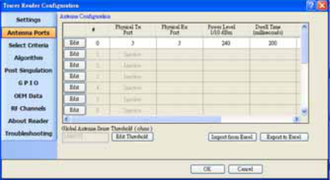
3.4.2 Antenna Configuration Page
From the Antenna Configuration page, you can configure power level . The
maximum power level setting of RU-824 is limited at +24dBm.
Figure 11 Antenna Configuration Dialog Box
3.4.3 Select Criteria Page
Use the Select Criteria page to view and configure the selection criteria query
settings that can be used for any tag–protocol operations. As shown in the
MICROELECTRONICS TECHNOLOGY INC. P.16
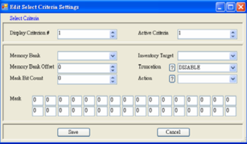
figure below, this page displays the active selection criteria of the current
reader.
The Display Criterion # spin box allows you to select the criteria currently
being viewed. It has a range of one (1) up to the value displayed under Active
Criteria.
The Load button causes the application to perform a direct query to the current
reader and reload the page with the retrieved select criteria settings.
To change the select criteria parameters for the active reader, click the Edit
button. This displays the dialog box shown in the figure below.
Figure 12 Select Criteria Edit Dialog
This panel allows configuration of individual select criterion parameters.
Note 1: Only one active select criteria is allowed at this time. Attempts to set
the Active Criteria count (in the Edit dialog) greater than one (1) results in an
Invalid Parameter error. This error is generated and displayed when the Save
button is clicked.
3.4.4 Inventory Algorithm Panel
The Inventory Algorithm panels are used to view and configure the reader’s
MICROELECTRONICS TECHNOLOGY INC. P.17
query settings, the parameters for the selected singulation algorithm, and
whether select and post singulation filters should be utilized during inventory,
read, write and similar operations.
The figure below shows an example of the Inventory Algorithm View panel.
The Load button queries the current reader and refreshes the values displayed
on the Algorithm Settings page.
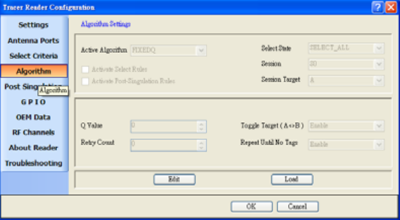
To modify the algorithm settings for the current reader, click the Edit
button. This opens a dialog box similar to the one shown in the figure
below.
Figure 13 Inventory Algorithm Edit Page
In the Active Algorithm dropdown box, you can select between the Fixed Q
and Dyanmic Q algorithm. When you select a new algorithm, the configurable
fields displayed in the center sub-panel change to match those available with
the selected algorithm.
The Activate Select Rules and Active Post-Singulation Rules checkboxes
control whether the select and post singulation criteria that have been
configured should be utilized during inventory, read, write, and similar
operations.
MICROELECTRONICS TECHNOLOGY INC. P.18
3.4.5 Post Singulation Criteria Page
Use the Post Singulation page to view and configure reader settings that
define the manner in which tags and post singulation are filtered (based on all or
part of the tag’s EPC).
The Display Criterion # spin box allows you to select the criteria currently
being viewed. It has a range of one (1) up to the value displayed under Active
Criteria.
The Load button causes the application to perform a direct query to the current
reader and reload the page with the retrieved post singulation criteria settings.
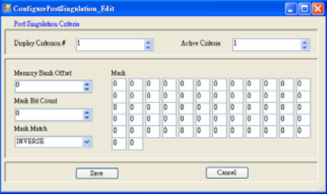
To change the post singulation criteria parameters for the active reader, click
the Edit button. This displays the dialog box shown in the figure below.
Figure 14 Post Singulation Criteria Edit Dialog
This page allows configuration of individual post singulation criterion
parameters.
Note: Only one active post singulation criteria is allowed at this time. Attempts
to set the Active Criteria count greater than one (1) in the Edit dialog result in
an Invalid Parameter error. This error is generated and displayed when the
Save button is clicked.
MICROELECTRONICS TECHNOLOGY INC. P.19
3.4.6 GPIO Pin Configuration Page
RU-824 does not support GPIO configuration
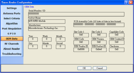
3.4.7 OEM Data Page
The OEM Data page allows the user to read product data from the OEM area
on the Indy Firmware microcontroller.
Figure 15 Inventory Algorithm Edit Page
3.4.8 RF Channel Definitions Page
The RF (Radio Frequency) Channel Definitions page provides to view the
reader’s frequency channels. An example of this page is shown below in the
figure below. The table is limited by F/W configuration.
MICROELECTRONICS TECHNOLOGY INC. P.20
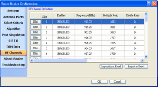
Figure 16 RF Channels Page
MICROELECTRONICS TECHNOLOGY INC. P.21

the detail channel definition of US and EU band are as follow.
Channel Frequency Channel Frequency
Channel 0 902.75 MHz Channel 25 915.25 MHz
Channel 1 903.25 MHz Channel 26 915.75 MHz
Channel 2 903.75 MHz Channel 27 916.25 MHz
Channel 3 904.25 MHz Channel 28 916.75 MHz
Channel 4 904.75 MHz Channel 29 917.25 MHz
Channel 5 905.25 MHz Channel 30 917.75 MHz
Channel 6 905.75 MHz Channel 31 918.25 MHz
Channel 7 906.25 MHz Channel 32 918.75 MHz
Channel 8 906.75 MHz Channel 33 919.25 MHz
Channel 9 907.25 MHz Channel 34 919.75 MHz
Channel 10 907.75 MHz Channel 35 920.25 MHz
Channel 11 908.25 MHz Channel 36 920.75 MHz
Channel 12 908.75 MHz Channel 37 921.25 MHz
Channel 13 909.25 MHz Channel 38 921.75 MHz
Channel 14 909.75 MHz Channel 39 922.25 MHz
Channel 15 910.25 MHz Channel 40 922.75 MHz
Channel 16 910.75 MHz Channel 41 923.25 MHz
Channel 17 911.25 MHz Channel 42 923.75 MHz
Channel 18 911.75 MHz Channel 43 924.25 MHz
Channel 19 912.25 MHz Channel 44 924.75 MHz
Channel 20 912.75 MHz Channel 45 925.25 MHz
Channel 21 913.25 MHz Channel 46 925.75 MHz
Channel 22 913.75 MHz Channel 47 926.25 MHz
Channel 23 914.25 MHz Channel 48 926.75 MHz
Channel 24 914.75 MHz Channel 49 927.25 MHz
Table 2 Operating channel definition in RU-824-100
Channel Frequency
Channel 0 865.7 MHz*
Channel 1 866.3 MHz*
Channel 2 866.9 MHz*
Channel 3 867.5 MHz*
Table 3 Operating channel definition in RU-824-110
3.4.9 About Reader Page
The About Reader page is a static page that provides versioning information
for the Indy components of the reader. It provides a single place to find the
MICROELECTRONICS TECHNOLOGY INC. P.22
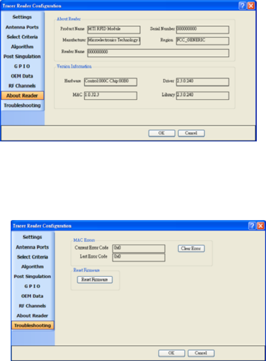
version information for the Indy device, Indy Firmware, Indy USB host driver,
and Indy Host Library API Interface. The figure below shows a sample About
Page.
Figure 17 About Reader Page
3.4.10 Troubleshooting Panel
The Troubleshooting page provides access to the Indy Firmware error register
as well as the ability to clear the error and reset the Indy Firmware. See the
figure below.
MICROELECTRONICS TECHNOLOGY INC. P.23
MICROELECTRONICS TECHNOLOGY INC. P.24
Figure 18 Troubleshooting Page
Note: Performing a Reset Firmware operation causes a reset of the connection
to the current reader. The reader will no longer be accessible via the application
until the application is restarted.
Appendix A: Federal Communication
Commission Interference Statement
This equipment has been tested and found to comply with the limits for a Class B digital
device, pursuant to Part 15 of the FCC Rules. These limits are designed to provide
reasonable protection against harmful interference in a residential installation. This
equipment generates, uses and radiates radio frequency energy and, if not installed and
used in accordance with the instructions, may cause harmful interference to radio
communications. However, there is no guarantee that interference will not occur in a
particular installation. If this equipment does cause harmful interference to radio or
television reception, which can be determined by turning the equipment off and on, the
user is encouraged to try to correct the interference by one of the following measures:
- Reorient or relocate the receiving antenna.
- Increase the separation between the equipment and receiver.
- Connect the equipment into an outlet on a circuit different from that to which the
receiver is connected.
- Consult the dealer or an experienced radio/TV technician for help.
This device complies with Part 15 of the FCC Rules. Operation is subject to the following
two conditions: (1) This device may not cause harmful interference, and (2) this device
must accept any interference received, including interference that may cause undesired
operation.
FCC Caution: Any changes or modifications not expressly approved by the party
responsible for compliance could void the user's authority to operate this equipment.
FCC RF Radiation Exposure Statement:
1. This Transmitter must not be co-located or operating in conjunction with any other
antenna or transmitter.
2. This equipment complies with FCC RF radiation exposure limits set forth for an
uncontrolled environment.
This device was tested for operations with the device maintained the use of distance 5mm
to the human body to the back side of the Phantom. To maintain compliance with FCC RF
exposure compliance requirements, avoid direct contact to the transmitting antenna during
transmitting.
MICROELECTRONICS TECHNOLOGY INC. P.25
MICROELECTRONICS TECHNOLOGY INC. P.26
Appendix B: Declaration of Conformity for
R&TTE Directive 99/5/EC
We,
MICROELECTRONICS TECHNOLOGY INC.
________________________________________________________________________
_
Hereby, declare that the essential requirements set out in the R&TTE Directive 99/5/EC
have been fully fulfilled on our product with indication below:
Product Name: RFID UHF USB READER
Model / Brand Name: RU-824 /MTI
The following standards have been applied for the investigation of compliance:
(Radio Standard Name) (Standard Version)ETSI EN 302 208-2 V1.3.1:2010
(EMC Standard Name) (Standard Version) ETSI EN 301 489-1 V1.8.1 2008-4
ETSI EN 301 489-3 V1.4.1 2002-08
(Safety Standard Name) (Standard Version)EN 60950-1:2006+A11:2009
(EMF Standard Name) (Standard Version) EN62311:2008
And apply notified body assessment:
Notified Body number 0700
PHOENIX TESTLAB GmbH
Königswinkel 10
D-32825 Blomberg
Germany
Furthermore, the ISO requirement for the in-process quality control procedure as well as
the manufacturing process has been reached. The technical document as well as the test
reports will be kept for a period at least 10 years after the last product has been
manufactured at the disposal of the relevant national authorities of any Member State for
inspection.
Detail contact information for this declaration has been listed below as the window of any

issues relevant for this declaration.
European Representative Manufacturer Contact
Company: MICROELECTRONICS TECHNOLOGY INC.
Address: No.1,Innovation Road II, Hsinchu
Science Park,Hsinchu 300, Taiwan, R.O.C.
Name/Title: Michael Lee/Section Manager
TEL: 886-3-577-3335
FAX: 886-3-578-1466
Email: lee_michael@mti.com.tw
2010-10-26
Signature Date
Company: MICROELECTRONICS ECHNOLOGY INC.
A
ddress: No.1,Innovation Road II, Hsinchu
Science Park,Hsinchu 300, Taiwan, R.O.C.
Name/Title: Michael Lee/Section Manager
TEL: 886-3-577-3335
FAX: 886-3-578-1466
Email: lee_michael@mti.com.tw
2010-10-26
Signature Date
MICROELECTRONICS TECHNOLOGY INC. P.27