Microhard Systems VIP4GABGN20 LTE Ethernet Bridge / Serial Gateway User Manual 2 of 2
Microhard Systems Inc LTE Ethernet Bridge / Serial Gateway 2 of 2
UserManual.wiki
>
Microhard Systems
>
VIP4GABGN20 User Manual
>
User Manual 2 of 2
Contents
1.
User manual
2.
User Manual 1 of 2
3.
User Manual 2 of 2
User Manual 2 of 2
Navigation menu
Upload a User Manual
Namespaces
Wiki Guide
HTML
PDF
Info
Views
User Manual
Discussion / Help
Navigation
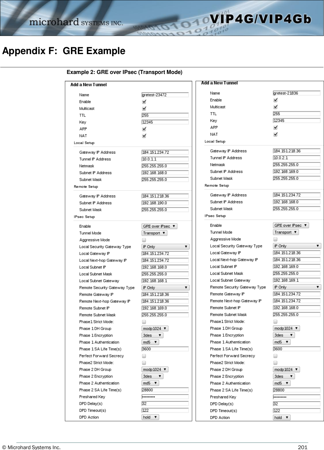
![© Microhard Systems Inc. 101 4.0 Configuration IP Protocol Config (Continued…) SMS Transparent Mode: Serial data from the COM1 port can be send to one or multiple destinations via SMS text messaging. SMS messages received by the VIP4G can also be sent to the COM1 port. Message Max Size Enter the maximum message size. Once the number of characters has been reached the VIP4G will package the data up and send it as a SMS message to the number(s) specified. [1….160]. The character timeout can be used to send messages more frequently by detecting a pause in the incoming data. Default: 160 Reply Timeout(s) Enter a value for the Reply Timeout in seconds. Default: 10 Access Control By selecting Anonymous, the VIP4G will accept a SMS message from any number. If Control Phone List is selected, only messages from the numbers in the Access Control List will be accepted. Default: Anonymous Read SMS Control Select Keep in SIM Card to save incoming SMS messages in the SIM card, select Delete to delete messages once they have been output to serial port. Default: Keep in SIM Card Access Control Phone List Messages can be sent to up to five (5) numbers, also, this list can be used to filter incoming SMS messages (See Access Control) Default: None Image 4-5-3: Comport > SMS Transparent Mode](https://usermanual.wiki/Microhard-Systems/VIP4GABGN20.User-Manual-2-of-2/User-Guide-3100603-Page-1.png)
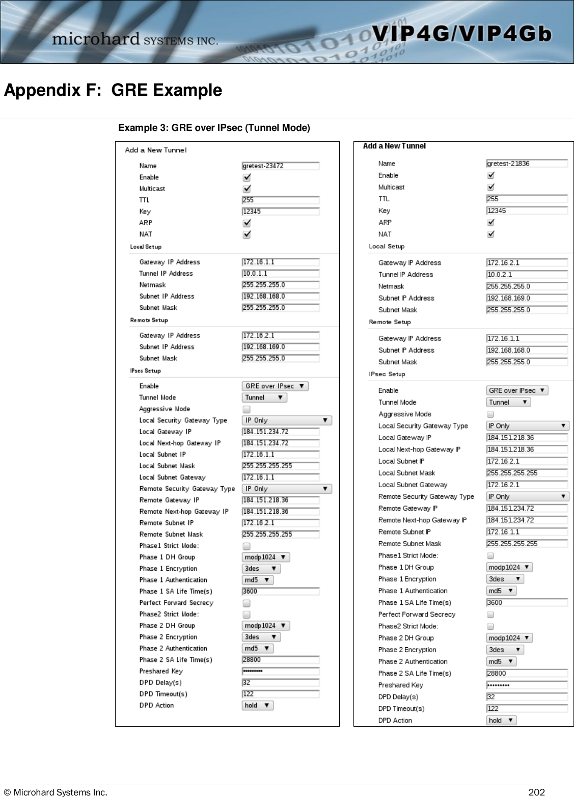
![© Microhard Systems Inc. 172 5.0 AT Command Line Interface AT+CMGR Command Syntax This command allows the application to read stored messages. The messages are read from the SIM card memory. AT+CMGR=<index> Description Example Input: AT+CMGR=<index><enter> Response: +CMGR: <stat>,<oa>,,<dt> <data> OK Parameters: <index> Index in SIM card storage of the message <stat> Status of Message in Memory (Text Mode) “REC UNREAD” Received unread messages “REC READ” Received read messages <oa> Originator Address String type <dt> Discharge Time String format: "yy/MM/dd,hh:mm:ss±zz" (year [00-99]/ month [01-12]/Day [01-31], Hour:Min:Second and TimeZone [quarters of an hour]) <data> SMS User Data in Text Mode String type AT+CMGL Command Syntax This command allows the application to read stored messages by indicating the type of the message to read. The messages are read from the SIM card memory. AT+CMGL=<status> Status: 0 - Lists all unread messages 1 - Lists all read messages 4 - Lists all messages Description Example Input: AT+CMGL=1 <enter> Response: AT+CMGL=1 +CMGL: 0,"REC READ","+14035553776",,"2013/10/04,11:12:27-06" Test Message 1 +CMGL: 1,"REC READ","+14035553776",,"2013/10/04,11:12:53-06" Test Message 2 +CMGL: 2,"REC READ","+14035553776",,"2013/10/04,11:13:06-06" Another test message! OK](https://usermanual.wiki/Microhard-Systems/VIP4GABGN20.User-Manual-2-of-2/User-Guide-3100603-Page-72.png)
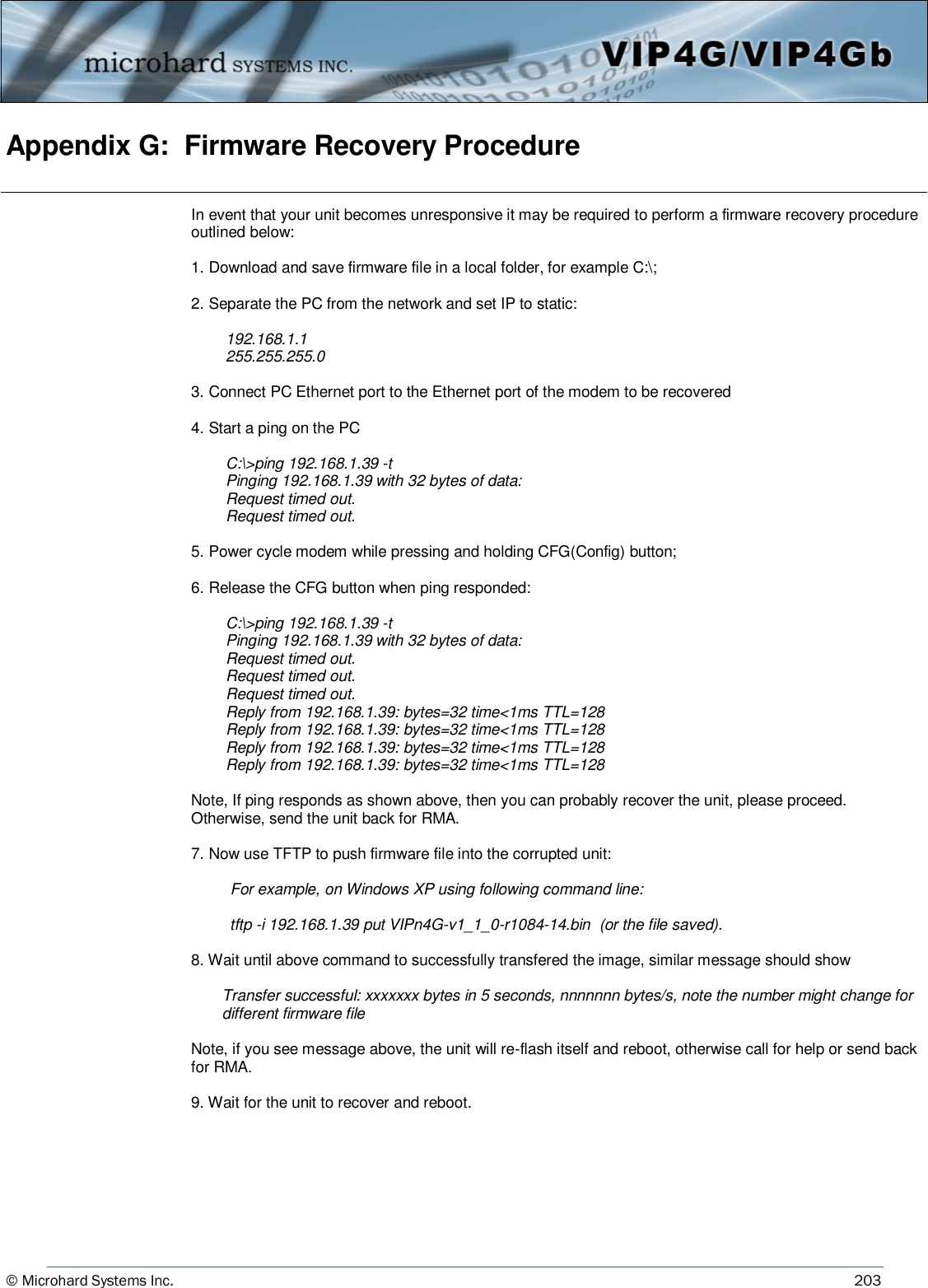
![© Microhard Systems Inc. 179 5.0 AT Command Line Interface AT+MTWT Command Syntax Enable/Disable the Wireless Traffic Timeout. Unit will reset if it does not see any traffic from the carrier for the amount of time defined. AT+MTWT=<Mode>[,<Interval_s>,<Reboot Time Limit_s>] Mode: 0 Disable 1 Enable Reboot Time Limit:300-60000 Description Example Input: AT+MTWT=1,1,300 <enter> Response: OK AT+MRTF Command Syntax Reset the modem to the factory default settings stored in non-volatile (NV) memory. Unit will reboot with default settings. AT+MRTF <action> Action: 0 pre-set action 1 confirm action OK Description Example Input: AT+MRTF=1 <enter> Response: OK AT+MSCMD Command Syntax Enable/Disable the Wireless Traffic Timeout. Unit will reset if it does not see any traffic from the carrier for the amount of time defined. AT+MSCMD=<Mode>[,<Filter Mode>[,<Phone No.1>[,...,<Phone No.6>]]] Mode: 0 Disable 1 Enable SMS Command Filter Mode: 0 Disable 1 Enable Phone Filter OK Description Example Input: AT+MSCMD=1,1,403556767,4057890909<enter> Response: OK](https://usermanual.wiki/Microhard-Systems/VIP4GABGN20.User-Manual-2-of-2/User-Guide-3100603-Page-79.png)
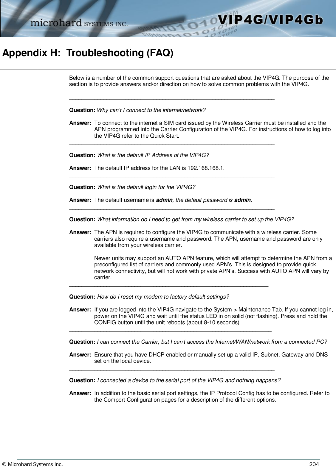
![© Microhard Systems Inc. 182 5.0 AT Command Line Interface AT+MEURD1 AT+MEURD2 AT+MEURD3 Command Syntax Define Event Report UDP Report No.1/2/3. AT+MEURD1=<Mode>[,<Remote IP>,<Remote Port>,<Interval Ti me_s>] Mode: 0 Disable 1 Moden Event Report 2 SDP Event Report 3 Management Report Description Example Input: AT+MIKAC=www.google.com,600,10<enter> Response: OK AT+MNMSR Command Syntax Define NMS Report. AT+MNMSR=<Mode>[,<Remote Port>,<Interval Time_s>] Mode: 0 Disable 1 Enable NMS Report Description Example Input: AT+MNMSR=1,20200,300<enter> Response: OK AT+MGPSR1 AT+MGPSR2 AT+MGPSR3 AT+MGPSR4 Command Syntax Define GPS Report No.1/2/3/4. AT+MGPSR1=<Mode>[,<Remote IP>,<Remote Port>,<Interval Ti me_s>] Mode: 0 Disable 1 Enable UDP Report Description Example Input: AT+MGPSR1=1,192.168.168.25,20175,600 <enter> Response: OK](https://usermanual.wiki/Microhard-Systems/VIP4GABGN20.User-Manual-2-of-2/User-Guide-3100603-Page-82.png)
![© Microhard Systems Inc. 188 5.0 AT Command Line Interface AT+MIS Command Syntax Module Input Status. AT+MIS Description Example Input: AT+MIS <enter> Response: +MIS: available input status INPUT 1: 0 open OK AT+MOS Command Syntax Module Output Status. AT+MOS=<Mode>[,<Setting No.>,<Status>] Mode: 0 All Output Status 1 Output Setting Setting No.: 1, 2, 3, 4(if output available) Status: 0 open 1 close Description Example Input: AT+MOS=0 <enter> Response: +MOS: available output status OUTPUT 1: 0 open OK Input: AT+MOS=1,1,1 <enter> Response: OK](https://usermanual.wiki/Microhard-Systems/VIP4GABGN20.User-Manual-2-of-2/User-Guide-3100603-Page-88.png)