Microhard Systems VIP4GABGN20 LTE Ethernet Bridge / Serial Gateway User Manual 2 of 2
Microhard Systems Inc LTE Ethernet Bridge / Serial Gateway 2 of 2
Contents
- 1. User manual
- 2. User Manual 1 of 2
- 3. User Manual 2 of 2
User Manual 2 of 2
© Microhard Systems Inc. 101
4.0 Configuration
IP Protocol Config (Continued…)
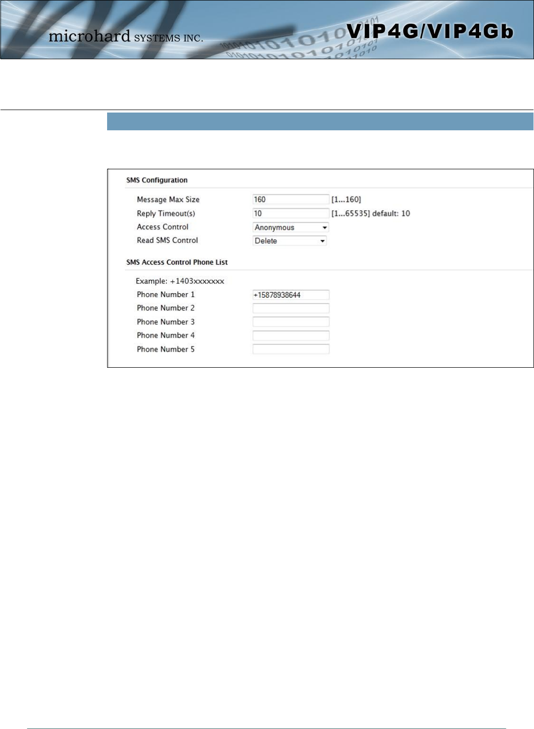
SMS Transparent Mode: Serial data from the COM1 port can be send to one or multiple destinations via
SMS text messaging. SMS messages received by the VIP4G can also be sent to the COM1 port.
Message Max Size
Enter the maximum message size. Once the number of characters has been reached the
VIP4G will package the data up and send it as a SMS message to the number(s) specified.
[1….160]. The character timeout can be used to send messages more frequently by detecting
a pause in the incoming data.
Default: 160
Reply Timeout(s)
Enter a value for the Reply Timeout in seconds.
Default: 10
Access Control
By selecting Anonymous, the VIP4G will accept a SMS message from any number. If
Control Phone List is selected, only messages from the numbers in the Access Control List
will be accepted.
Default: Anonymous
Read SMS Control
Select Keep in SIM Card to save incoming SMS messages in the SIM card, select Delete to
delete messages once they have been output to serial port.
Default: Keep in SIM Card
Access Control Phone List
Messages can be sent to up to five (5) numbers, also, this list can be used to filter incoming
SMS messages (See Access Control)
Default: None
Image 4-5-3: Comport > SMS Transparent Mode
© Microhard Systems Inc. 102
4.0 Configuration
IP Protocol Config (Continued…)
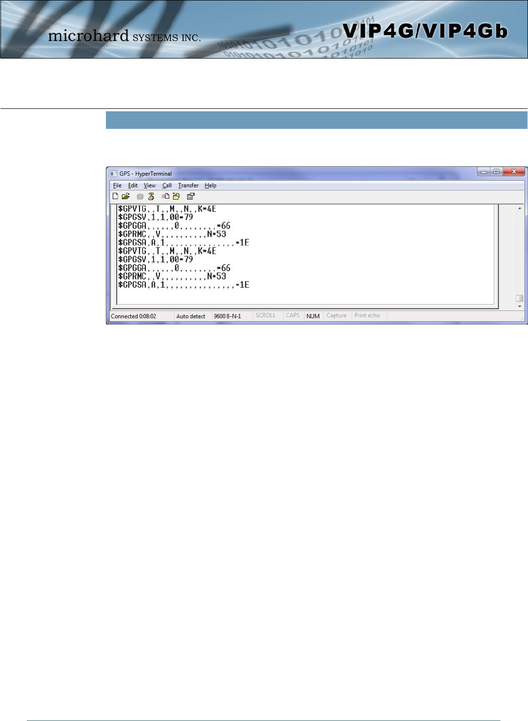
GPS Transparent Mode: When in GPS Transparent Mode, GPS data is reported out the serial port at 1
second intervals. Sample output is shown below:
Image 4-5-4: Comport > GPS Transparent Mode
© Microhard Systems Inc. 103
4.0 Configuration
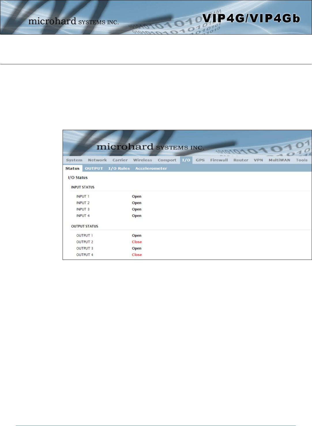
Image 4-6-1: I/O > Status
4.6 I/O
4.6.1 I/O > Status
The VIP4G has 4 status inputs, which can be used with various alarms and sensors for monitoring, telling
the modem when certain events have occurred, such as an intrusion alarm on a door, a temperature
threshold has been exceed, or a generator has failed, out of fuel. Also included are 4 outputs, that can be
used to drive external relays to remotely control equipment and devices.
Input Status
The WebUI will display the current state of each input. The I/O pins are all normally open so an open status
indicates that there is nothing connected to the input pins, or that an event has not occurred to trigger the
input. The inputs have a small wetting current (Vin) used to detect a contact closure, and prevent false
readings by any noise or intermittent signals, it has a threshold sensitivity of 1.8V.
Output Status
The WebUI will display the current state of each control output. Using the Output menu discussed in the
next section, a user can remotely control the status of the output pins.
© Microhard Systems Inc. 104
4.0 Configuration
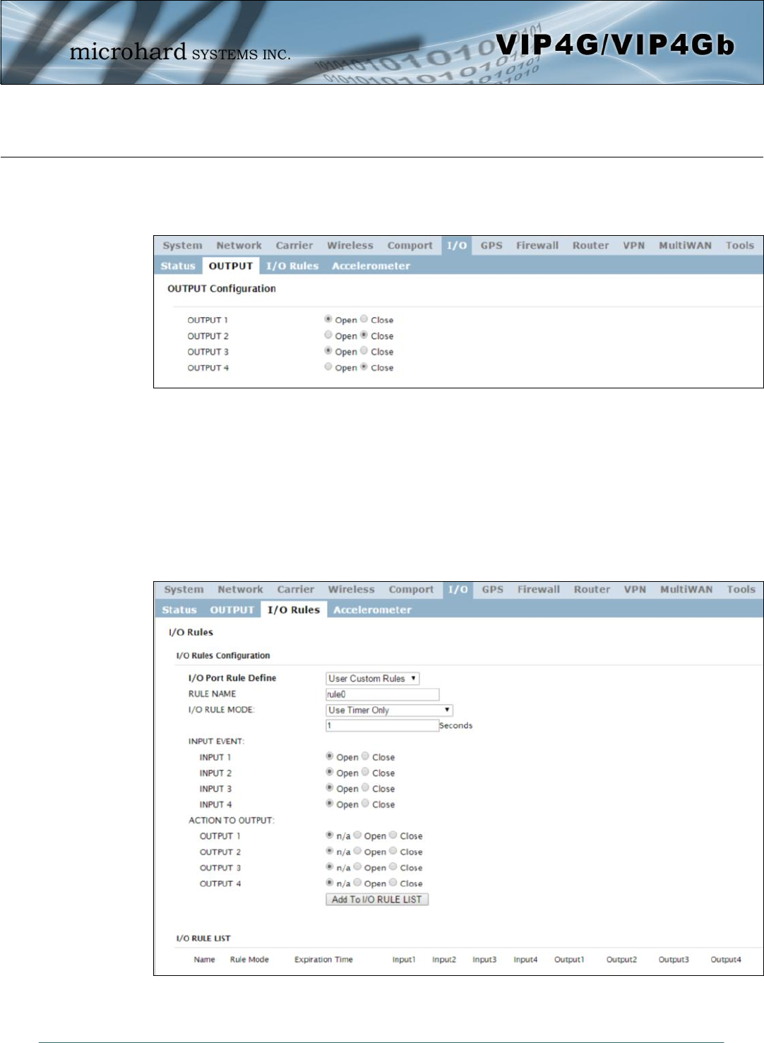
Image 4-6-2: I/O > OUTPUT
4.6.2 I/O > OUTPUT
Each of the 4 Outputs can be controlled separately, allowing a user to remotely trigger an event.
The output pins on the VIP4G can be used provide output signals, which can be used to drive an external
relay to control an external device. Maximum recommended load for the Output Pin is 150mA @ 32 VDC
(Vin)
4.6.3 I/O > I/O Rules
Custom rules can be applied to the I/O behavior, such as setting a output after a specified time,
or an input or combination of inputs triggering output(s).
Image 4-6-3: I/O > I/O Rules

© Microhard Systems Inc. 105
4.0 Configuration
I/O Port Rule Define
Set the type of I/O rules to perform:
Disabled: Outputs have no logical connection to inputs.
Default Rules:
Each input has a logical connection to each output as follows:
Input 1 -> Output 1
Input 2 -> Output 2
Input 3 -> Output 3
Input 4 -> Output 4
Custom Rules:
User can make custom rules to trigger output states. Custom rules can
contain any of the following I/O rules:
A timer has finished counting down
A input signal has changed state
A combination of a input state and a timer.
Values (selection)
Disable
Default Rules
Custom Rules
Rule Name
Each I/O rule must have a unique name. This is for reference purposes and
has no effect on the rule itself.
Values (characters)
rule0
I/O Rule Mode
Define the parameters of the desired rule:
Use Timer Only: Once the programmed timer has expired, the defined
output state will be triggered.
Use Input States Only: The VIP4G will set puts as defined based on input
states.
Use Input States With Timer: A combination of inputs states and a timer
would trigger an output action when the input state if changed for more
than the specified time.
Values (selection)
Use Timer Only
Use Input States Only
Use Input States With
Timer
© Microhard Systems Inc. 106
4.0 Configuration
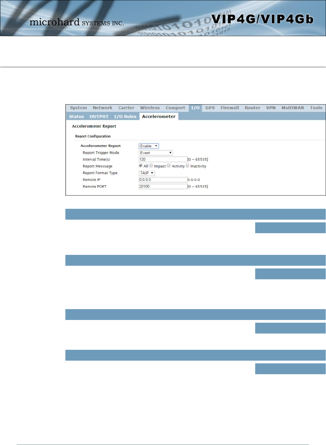
4.6.4 I/O > Accelerometer
The VIP4G has a internal Accelerometer, which can be configured to report events to a remote host based
on a specific physical activity.
Image 4-6-4: I/O > Accelerometer
Accelerometer Report
Enable or disable reporting by the Accelerometer. Values (selection)
Disable
Enable
Report Trigger Mode
Select reporting on event, timer or both. Values (selection)
Event
Timer
Event OR Timer
Interval
Set the time at which events will be reported if the timer feature is selected. Values (seconds)
120
Report Message
Select the types of events that cause a report to be sent. Values (selection)
ALL
Impact
Activity
Inactivity
© Microhard Systems Inc. 107
4.0 Configuration
Report Format Type
Select the format in which the report will be sent, TAIP or Text. Values (selection)
TAIP
Text
Remote IP
Enter the IP Address of the remote host. This is the address in
which the reports will be sent via UDP packets. Values (IP Address)
0.0.0.0
Remote PORT
Enter the UDP port number to send the reports. Values (Port)
20100
© Microhard Systems Inc. 108
4.0 Configuration
4.7 GPS
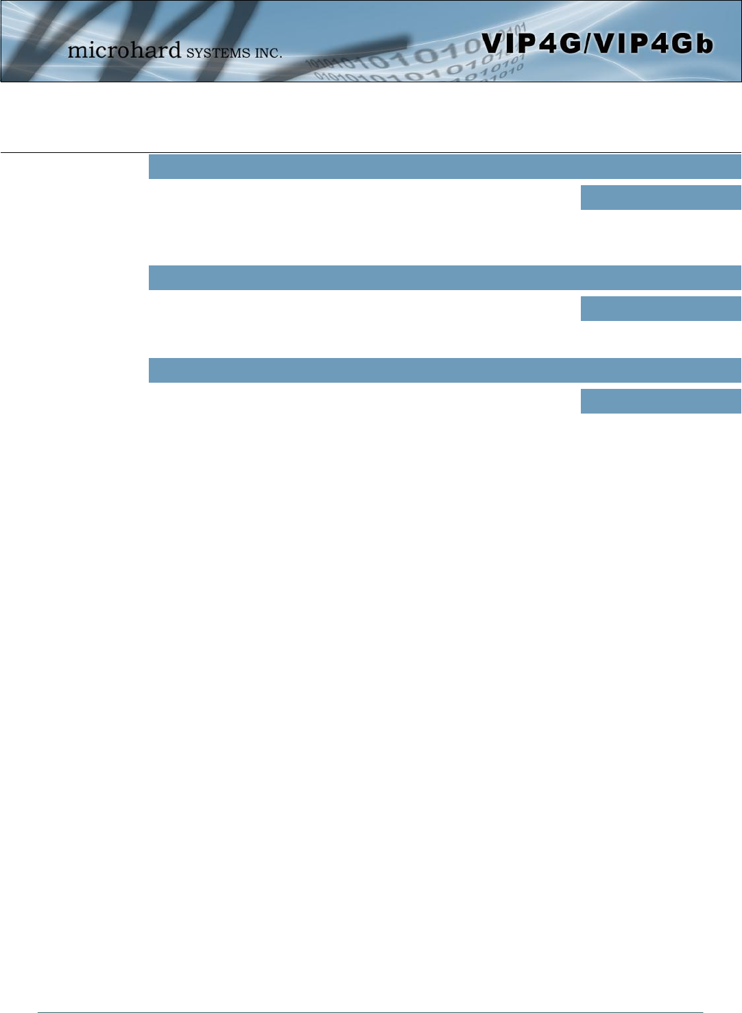
4.7.1 GPS > Location
Location Map
The location map shows the location on the VIP4G. The unit will attempt to get the GPS coordinates from
the built in GPS receiver, and if unsuccessful, will use the Cell ID location reported by the Cellular Carrier.
Image 4-7-1: GPS > Location Map
When using standalone GPS the specific coordinates are shown as in the above screenshot. If the VIP4G
is unable to locate GPS satellites, or if configured to use Embedded Carrier GPS, only the estimated
location of the VIP4G is shown with a radius drawn on the map.
© Microhard Systems Inc. 109
4.0 Configuration
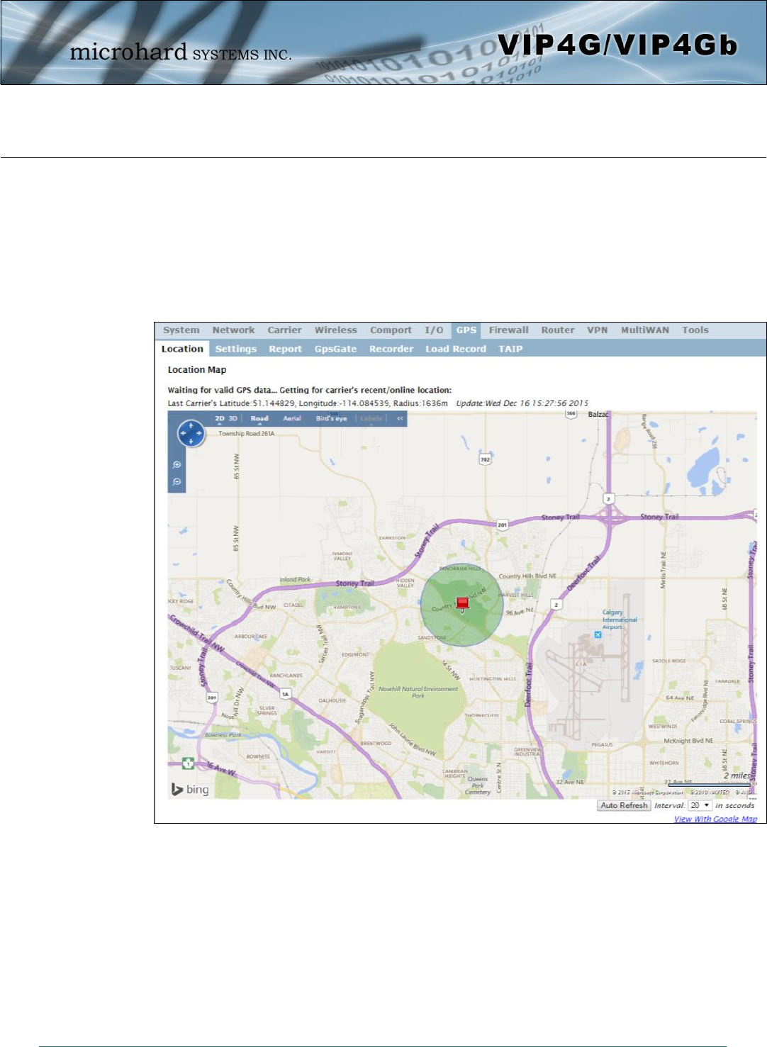
4.7.2 GPS > Settings
The VIP4G can be polled fro GPS data via GPSD standards and/or provide customizable reporting to up to
4 different hosts using UDP or Email Reporting.
GPS data can also be reported to the COM1 serial port. For more information, refer to the COM1 > IP
Protocol Config > GPS Transparent Mode section.
Image 4-7-2: GPS > Settings
GPS Status
Enable or disable the GPS polling function of the VIP4G. Values
Disable / Enable
GPS Source
Select the data source for GPS data. Values
Stand Alone GPS
Embedded Carrier GPS
TCP Port
Specify the TCP port on the VIP4G where the GPS service is running and
remote systems can connect and poll for GPSD data. Values
2947
© Microhard Systems Inc. 110
4.0 Configuration
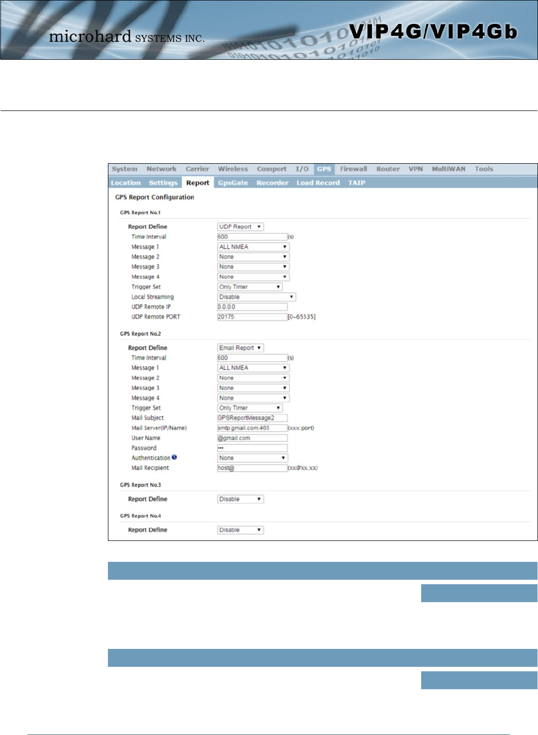
4.7.3 GPS > GPS Report
The VIP4G can provide customizable reporting to up to 4 hosts using UDP or Email Reporting.
Image 4-7-3: GPS > GPS Report
Report Define
Enable UDP and/or Email or disable GPS Reporting. Up to 4 reports can
be set up and configured independently. Values (selection)
Disable
UDP Report
Email Report
Time Interval
The interval timer specifies the frequency at which the GPS data is
reported in seconds. Values (seconds)
600
© Microhard Systems Inc. 111
4.0 Configuration
Message 1-4
The Message field allows customization of up to 4 different GPS messages
to be sent to the specified host.
None - Message is not used, no data will be sent
ALL - Sends all of the below
GGA - GPS Fix Data
GSA - Overall Satellite Data
GSV - Detailed Satellite Data
RMC - Recommended Min Data for GPS
VTG - Vector Track & Ground Speed
GPSGate - For use with GPSGate Tracking Software
Values (selection)
None
ALL NMEA
GGA
GSA
GSV
RMC
VTG
Latitude/Longitude
GPSGate UDP Protocol
Trigger Set
The trigger condition defines the conditions that must be met before a GPS
update is reported. If OR is chosen, the Repeater Timer OR the Distance
trigger conditions must be met before an update is sent. The AND
condition, requires that both the Repeat timer AND the Distance trigger
conditions be met before an update is sent.
Values (selection)
Only Timer
Timer AND Distance
Timer OR Distance
Distance Set
The distance parameter allows the GPS data to only be sent when a
specified distance has been traveled since the last report. Values (meters)
1000
UDP Remote IP / Port
This is the IP Address and port of the remote host in which the UDP
packets are to be sent. Values (Address/Port)
0.0.0.0 / 20175
Mail Subject
If an Email report is chosen, the subject line of the Email can be defined
here. Values (characters)
1000
Mail Server
If an Email report is to be sent, the outgoing mail server must be defined,
and the port number. Values (Address:port)
smtp.gmail.com:465
Username / Password
Some outgoing mail servers required username and password to prevent
an account being used for spam. Enter the login credentials here. Values (characters)
Username / password
Mail Recipient
Some outgoing mail servers require a username and password to prevent
an account being used for spam. Enter the login credentials here. Values (characters)
host@email.com
© Microhard Systems Inc. 112
4.0 Configuration
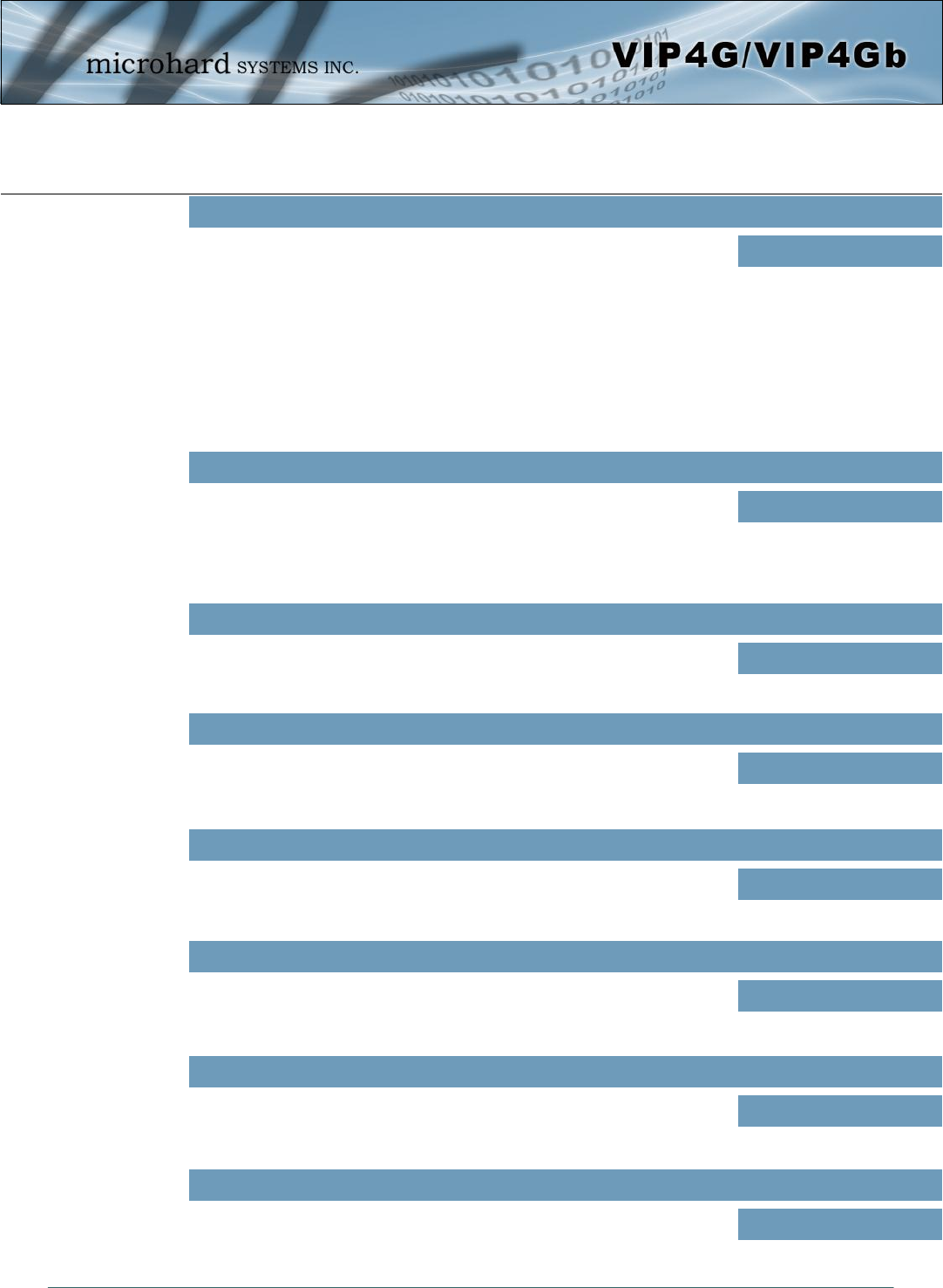
4.7.4 GPS > GpsGate
The VIP4G is compatible with GpsGate - GPS Tracking Software, which is a 3rd party mapping solution
used for various GPS services including vehicle and asset tracking The VIP4G can communicate with
GpsGate via Tracker Mode and TCP/IP. (UDP reporting can also send information to GpsGate, see the
GPS > Report - UDP Reports)
Image 4-7-4: GPS > GpsGate Tracker Mode
Mode Set
Enable GpsGate Tracker Mode or TCP modes. In tracker mode The VIP4G
and GpsGate software will communicate via TCP/IP, however if a
connection is not available it will attempt to use SMS messaging.
Values (selection)
Disable
Enable Tracker Mode
Enable TCP Send Mode
Server Command Channel
By default VIP4G and GpsGate will use TCP and SMS to ensure
communication between each other. It is also possible to specify TCP or
SMS communication only. Initial setup in Tracker mode must be via SMS.
Values (seconds)
TCP and SMS
TCP Only
SMS Only
TCP Alive Mode / Alive Time Interval
TCP alive mode will keep TCP connection alive if tracker is not enabled or
the tracker interval is too long. The default is 150 seconds. Values (seconds)
150
GpsGate - Tracker Mode
© Microhard Systems Inc. 113
4.0 Configuration
Setup Phone Filter
A phone number filter can be applied to prevent SMS commands not
intended for the VIP4G from being processed. Values (selection)
Disable: Accept All
Enable Filter
Motion Trigger
Use this parameter to enable or disable the motion trigger in the VIP4G. Values (selection)
Disable
Enable Motion Trigger
When GPS Invalid, Sending Data
Specify what happens when the GPS data is invalid, either use the last
valid position or do not use the last valid position. Values (selection)
Not Use Last Valid Position
Use Last Valid Position
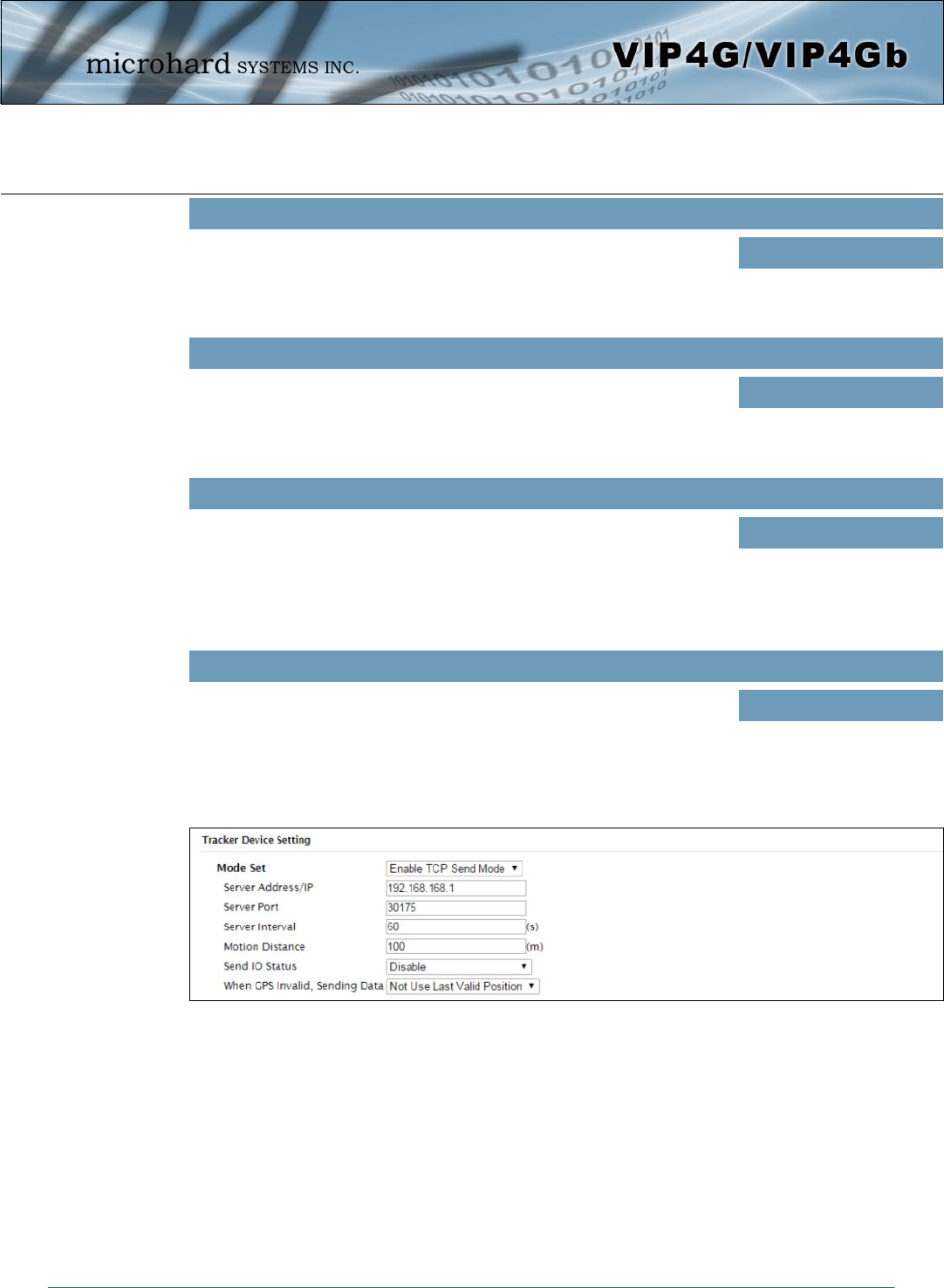
GpsGate - TCP Mode
Send IO Status
When enabled, the VIP4G will send the current status of the Digital I/O
inputs and/or outputs to the GpsGate Server. Values (selection)
Disable
Send Input Status
Send Output Status
Send Input&Output Status
Image 4-7-5: GPS > GpsGate TCP Mode
© Microhard Systems Inc. 114
4.0 Configuration
Mode Set
Enable GpsGate Tracker Mode or TCP modes. In TCP Mode the VIP4G
will establish a connection with the GpsGate Server directly without the
SMS setup process. If the TCP connection is not available, the VIP4G will
continue to try to connect every few seconds.
Values (selection)
Disable
Enable Tracker Mode
Enable TCP Send Mode
Server Address / IP
Enter the IP Address of the server running the GpsGate application. Values (IP Address)
192.168.168.1
Server Port
Enter the TCP Port of the server running the GpsGate application. Values (Port)
30175
Server Interval
Define the interval at which the VIP4G will send data to the GpsGate
Server. Values (seconds)
60
Motion Distance
Set the motion threshold in which the VIP4G will be triggered to send
location data. Values (meters)
100
When GPS Invalid, Sending Data
Specify what happens when the GPS data is invalid, either use the last
valid position or do not use the last valid position. Values (selection)
Not Use Last Valid Position
Use Last Valid Position
Send IO Status
When enabled, the VIP4G will send the current status of the Digital I/O
inputs and/or outputs to the GpsGate Server. Values (selection)
Disable
Send Input Status
Send Output Status
Send Input&Output Status
© Microhard Systems Inc. 115
4.0 Configuration
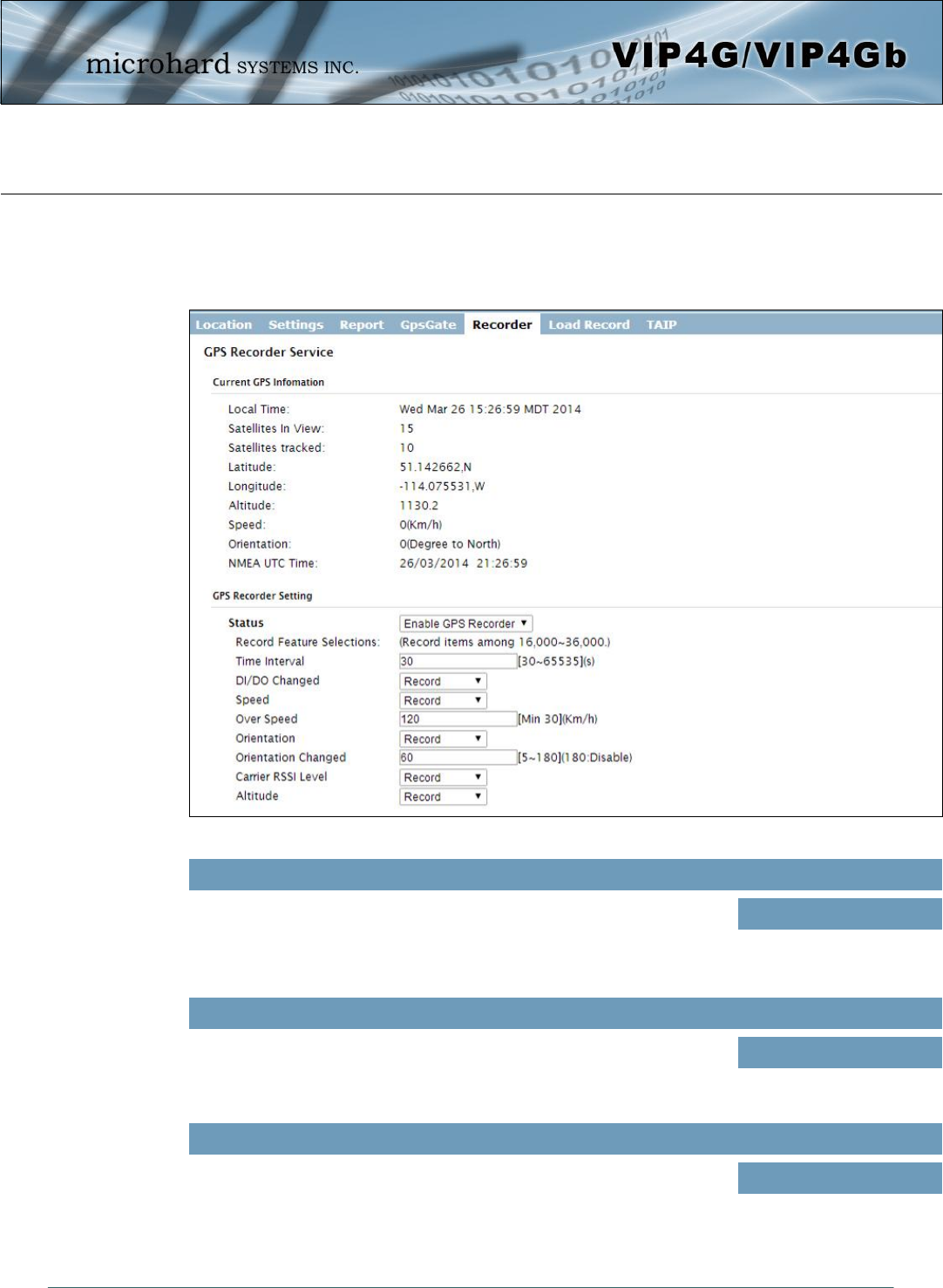
4.7.5 GPS > Recorder
The VIP4G can be configured to record events based on time intervals, and/or an event trigger and store
them in non-volatile memory. These events can then be viewed within the WebUI, on a map, or sent to a
remote server in a number of different formats.
Image 4-7-6: GPS > GPS Recorder Service
Status
Use the Status parameter to enable the GPS recording functionality of the
VIP4G. The total number of records that can be recorded varies between
16,000 and 36,000, depending on the number of GPS parameters that are
recorded.
Values (selection)
Disable
Enable GPS Recorder
Time Interval
Define the interval at which the VIP4G will record GPS data. If there is no
valid data available at the specified time (i.e. no connected satellites), the
unit will wait until the next time valid information is received.
Values (seconds)
300
DI/DO Changed
The VIP4G can detect and report the current GPS info when a digital input
or output status changes, regardless of the time interval setting. Values (selection)
Record / Don’t Record
© Microhard Systems Inc. 116
4.0 Configuration
Speed
Select Record to include the current speed in the reported data. Values (selection)
Record / Don’t Record
Over Speed
Trigger a GPS record entry when the speed has exceeded the configured
threshold. A minimum of 30 Km/hr is required. Values (Km/hr)
120
Orientation
Select Record to record the current orientation when a GPS entry is
recorded. (Degree to North). Values (selection)
Record / Don’t Record
Orientation Changed
Record a GPS, regardless of the time interval, if the orientation of the unit
changes. (5 ~ 180: 180 = Disable) Values (5 ~ 180)
60
Carrier RSSI Level
Select Record to record the current 4G/Cellular RSSI level when a GPS
entry is recorded. (-dB). Values (selection)
Record / Don’t Record
Altitude
Select Record to record the current Altitude when a GPS entry is recorded
(meters). Values (selection)
Record / Don’t Record
© Microhard Systems Inc. 117
4.0 Configuration
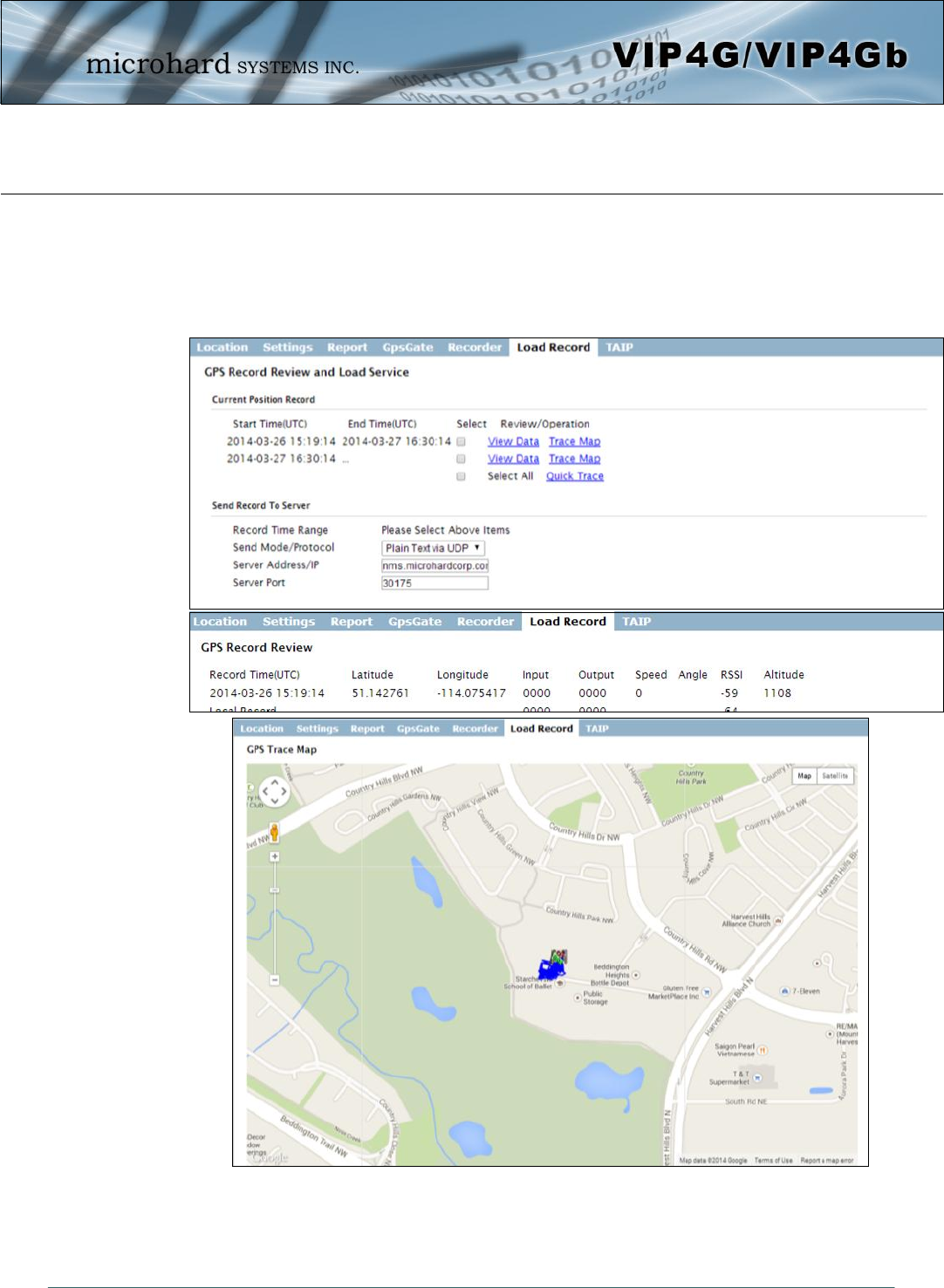
4.7.6 GPS > Load Record
Data that has been recorded and saved by the VIP4G can then be viewed or sent to a remote server in
various formats. The data recorded can also be viewed directly by selecting “View Data” and the data can
be traced on a map (internet access required), by selecting “Trace Map”, or “Quick Trace”. The
screenshots below show the raw data that can be viewed and the Trace Map/Quick Trace output.
Image 4-7-7: GPS > GPS Load Record
© Microhard Systems Inc. 118
4.0 Configuration
Record Time Range
Check the boxes next to the records listed above that are to be sent to the
server. Values (selection)
(no default)
Send Mode / Protocol
Specify the data format / protocol type for the data to be sent. Values (selection)
NMEA via UDP
NMEA via TCP
GpsGate via UDP
GpsGate via TCP
Plain Text via UDP
Plain Text via TCP
Server Address/IP
Enter the address or IP address of the remote server to which the data is to
be sent. Values (IP)
nms.microhardcorp.com
Server Port
Enter the UDP/TCP port number of the remote server to which the data is
to be sent. Values (Port)
30175
© Microhard Systems Inc. 119
4.0 Configuration
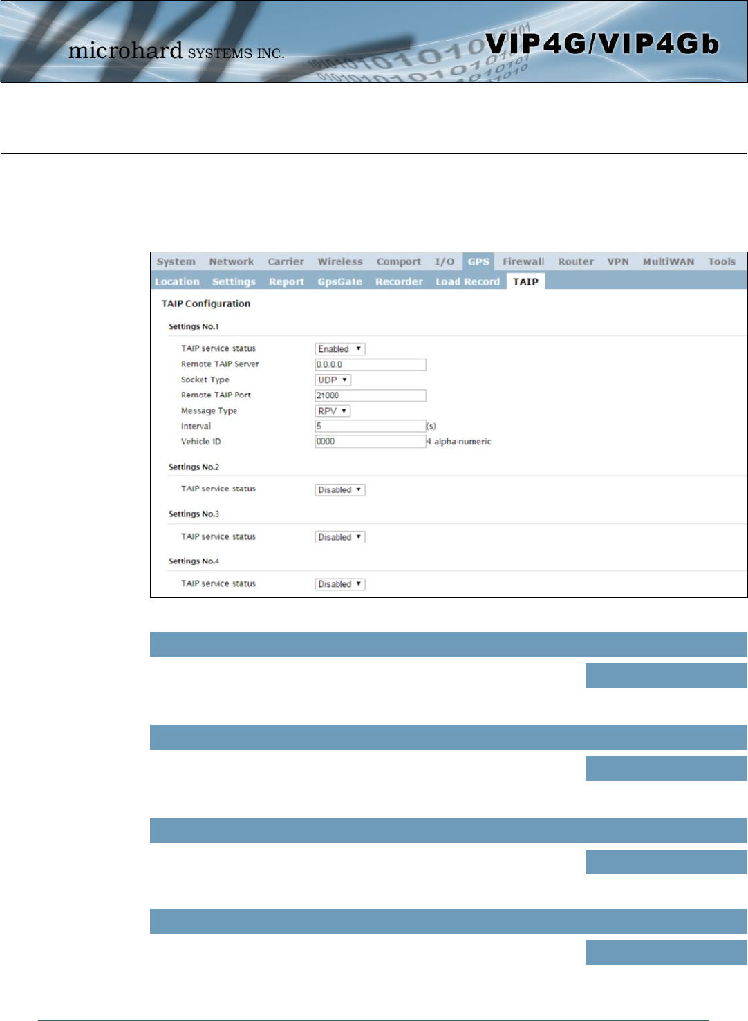
4.7.7 GPS > TAIP
The VIP4G has the ability to send GPS data in TAIP (Trimble ACSII Interface Protocol) format to up to 4
different TAIP servers. The following section describes the configuration parameters required to initialize
TAIP reporting.
Image 4-7-8: GPS > TAIP
TAIP service status
Enable or disable TAIP service on the VIP4G. The VIP4G can report TAIP
to up to 4 different hosts. Values (selection)
Enable / Disable
Remote TAIP Server
Enter the IP Address of the Remote TAIP Server. Values (IP Address)
0.0.0.0
Socket Type
Select the socket type that is used by the Remote TAIP server. Select TCP
or UDP, this will define how the connection (TCP) or data is sent (UDP) to
the server.
Values (selection)
UDP / TCP
Remote TAIP Port
Enter the TCP or UDP port number used on the Remote TAIP server. Values (TCP/UDP)
UDP / TCP
© Microhard Systems Inc. 120
4.0 Configuration
Message Type
Select between RPV and RLN message types.
RPV - Position/Velocity
RLN - Long Navigation Message
Values (selection)
RPV / RLN
Interval
Set the frequency at which TAIP messages are reported to the remote
server. The unit used is seconds, and the default value is 60 seconds. Values (seconds)
60
Vehicle ID
Set the Vehicle ID using 4 alpha-numeric characters. Values (chars)
0000
© Microhard Systems Inc. 121
4.0 Configuration
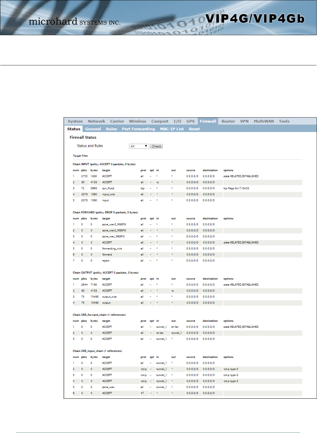
Image 4-8-1: Firewall > Status
4.8 Firewall
4.8.1 Firewall > Status
Firewall Status allows a user to see detailed information about how the firewall is operating. The All, Filter,
Nat, Raw, and Mangle options can be used to view different aspects of the firewall.
© Microhard Systems Inc. 122
4.0 Configuration
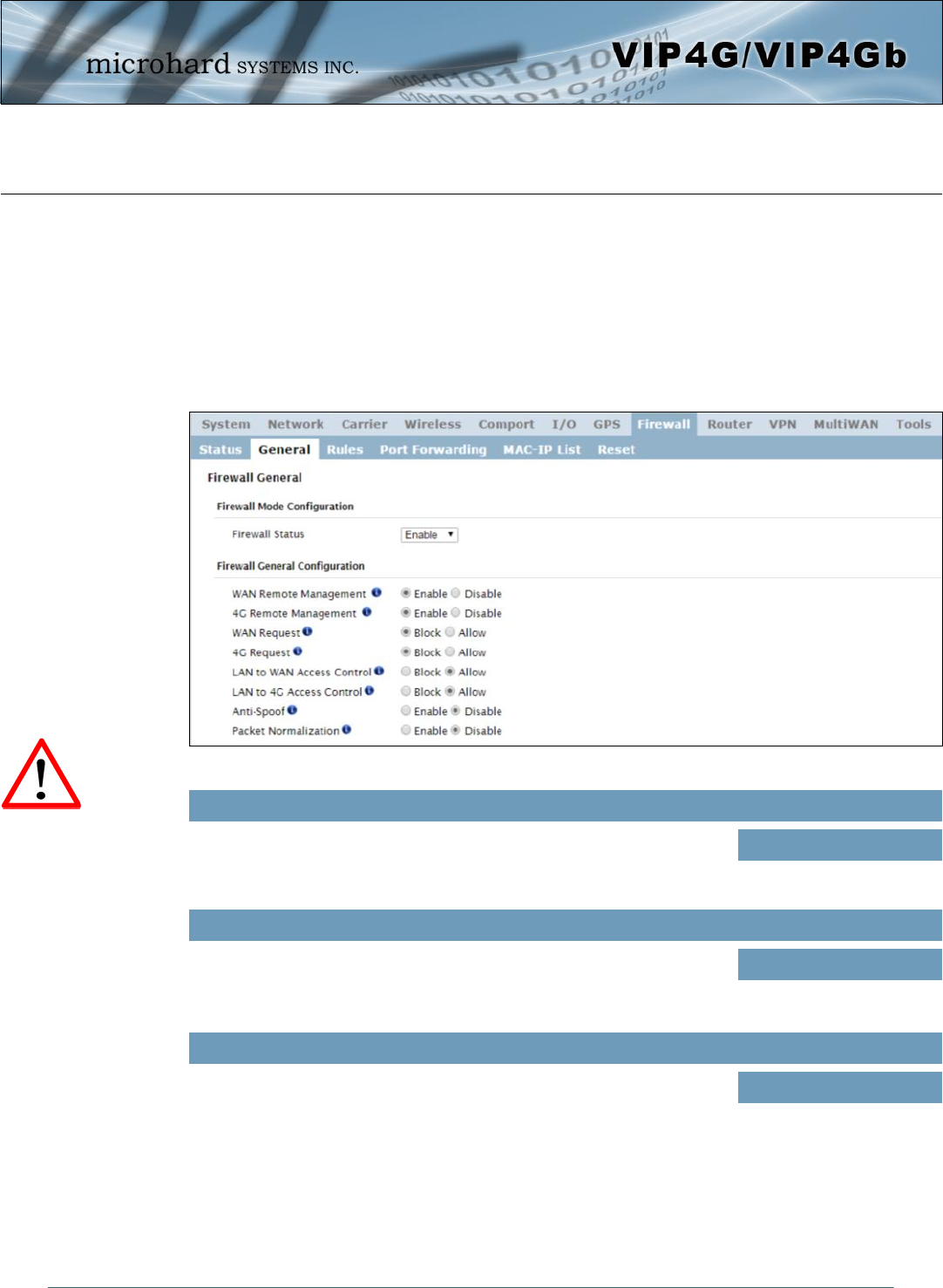
Image 4-8-2: Firewall > General
4.8.2 Firewall > General
The General Firewall settings allow users to enable or disable the firewall, and to decide which areas of the
modem to protect. The Firewall can also be reset to factory defaults from this area of the WebUI.
In a cellular device such as this, it is highly recommended to configure the firewall to protect any devices
connected to the modem, and to control data usage. This is especially important units set up with a public
IP address as the modem is effectively on the public internet and is susceptible to a wide range of threats
which may severely impact the data usage. This can be avoided by blocking all 4G/Cellular traffic and
setting up specific rules to either open only used ports, or even restrict access to specific IP/networks.
Firewall Status
When enabled, the firewall settings are in effect. When disabled, none of
the settings configured in the menu’s below have an effect, the modem is
“open” to anyone.
Values
Disable / Enable
WAN Remote Management
Allow remote management of the VIP4G on the WAN side using the WebUI
on port 80(HTTP), and 443 (HTTPS). If disabled, the configuration can only
be accessed from the LAN (or 4G if enabled)..
Values
Enable / Disable
4G Remote Management
Allow remote management of the VIP4G from the 4G side of using the
WebUI on port 80(HTTP), and 443 (HTTPS). If disabled, the configuration
can only be accessed from the LAN (or WAN if enabled)..
Values
Enable / Disable
For best practices and to
control data usage it is
critical that the firewall be
configured properly.
It is recommended to block
all incoming 4G/Cellular
traffic and create rules to
open specific ports and/or
use ACL lists to limit
incoming connections.
© Microhard Systems Inc. 123
4.0 Configuration
WAN Request
When Blocked the VIP4G will block all requests from devices on the WAN
unless specified otherwise in the Access Rules, MAC List, IP List
configurations. Access to ports 80 (HTTP) and 443 (HTTPS-if enabled), is
still available unless disabled in the WAN Remote Management option.
Values
Block / Allow
LAN to WAN Access Control
Allows or Blocks traffic from the LAN accessing the WAN unless specified
otherwise using the Access Rules, MAC, and IP List configuration. Values
Block / Allow
4G Request
When Blocked all requests from devices on the 4G (Wireless Carrier) side
will be blocked, unless specified otherwise in the Access Rules, MAC List,
IP List configurations. Access to ports 80 (HTTP) and 443 (HTTPS-if
enabled), is still available unless disabled in the 4G Remote Management
option.
Values
Block / Allow
LAN to 4G Access Control
Allows or Blocks traffic from the LAN accessing the 4G connection unless
specified otherwise using the Access Rules, MAC, and IP List
configuration.
Values
Block / Allow
Anti-Spoof
The Anti-Spoof protection is to create some firewall rules assigned to the
external interface (WAN & 4G/Cellular) of the firewall that examines the
source address of all packets crossing that interface coming from outside.
If the address belongs to the internal network or the firewall itself, the
packet is dropped.
Values
Enable / Disable
When 4G is set to ‘Allow’
the modem is open to
anyone, this is not
recommended as it may
impact data usage from
unwanted sources.
Packet Normalization
Packet Normalization is the normalization of packets so there are no
ambiguities in interpretation by the ultimate destination of the packet. The
scrub directive also reassembled fragmented packets, protecting some
operating systems from some forms of attack, and drops TCP packets that
have invalid flag combinations.
Values
Enable / Disable
© Microhard Systems Inc. 124
4.0 Configuration
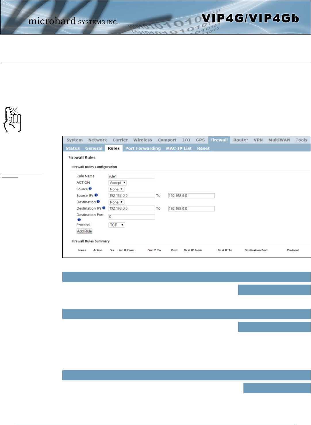
Image 4-8-3: Firewall > Rules
4.8.3 Firewall > Rules
Once the firewall is turned on, rules configuration can be used to define specific rules on how local and
remote devices access different ports and services. MAC List and IP List are used for general access, and
are applied before rules are processed.
It is highly recommended to block as much traffic as possible from the modem, especially when using a
public IP address. The best security would to be to allow traffic only from trusted IP addresses, and only
the specific ports being used, and block everything else. Not configuring the firewall and the firewall rules
correctly could result in unpredictable data charges from the cellular carrier.
Rule Name
The rule name is used to identify the created rule. Each rule must have a
unique name and up to 10 characters can be used. Values (10 Chars)
characters
Action
The Action is used to define how the rule handles the connection request.
ACCEPT will allow a connection, while REJECT (error) and DROP
(quietly dropped), will refuse connections.
This is configured based on how the WAN/4G Request and LAN to
WAN/4G Access Control are configured in the previous menus.
Values (selection)
ACCEPT
DROP
REJECT
Source
Select the zone which is to be the source of the data traffic. WAN applies
to the WAN RJ45 connection, and 4G refers to the connection to the
cellular carrier. The LAN refers to local connections on the VIP4G
(Ethernet/WiFi).
Values
LAN / 4G / WIFI / WAN
None
Refer to Appendix D for an
example of how to set up a
firewall to block all
connections and then add
access to only specific IP’s
and Ports.
Appendix D: Firewall
Example
© Microhard Systems Inc. 125
4.0 Configuration
Source IPs
Match incoming traffic from the specified source IP range. Boxes accept
single IP Addresses without network masks, example: 192.168.1.0 to
192.168.1.255 represents all IP Addresses in the 192.168.1.0/24 network.
(Put same IP in both boxes for a single IP match.)
Values (IP Address)
192.168.0.0 to
192.168.0.0
Destination
Select the zone which is the intended destination of the data traffic. WAN
applies to the wireless connection to the cellular carrier and the LAN refers
to local connections on the VIP4G (Ethernet/WiFi)
Values (selection)
LAN / 4G / WIFI / WAN
None
Destination IPs
Match incoming traffic from the specified destination IP range. Boxes
accept single IP Addresses without network masks, example: 192.168.1.0
to 192.168.1.255 represents all IP Addresses in the 192.168.1.0/24
network. (Put same IP in both boxes for a single IP match.)
Values (IP Address)
192.168.0.0 to
192.168.0.0
Destination Port
Match incoming traffic directed at the given destination port or port range.
(To specify a port range use a From:To (100:200) format)
Values (port)
0
Protocol
The protocol field defines the transport protocol type controlled by the rule. Values
TCP
UDP
Both
ICMP
© Microhard Systems Inc. 126
4.0 Configuration
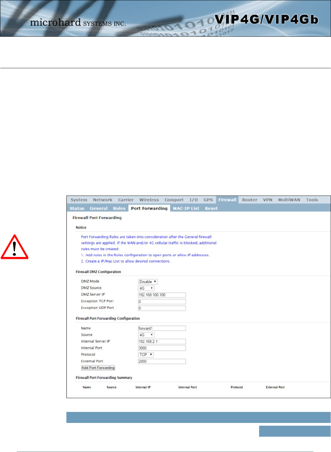
Image 4-8-4: Firewall > Port Forwarding
4.8.4 Firewall > Port Forwarding
The VIP4G can be used to provide remote access to connected devices. To access these devices a user
must define how incoming traffic is handled by the VIP4G. If all incoming traffic is intended for a specific
connected device, DMZ could be used to simplify the process, as all incoming traffic can be directed
towards a specific IP address.
In the case where there is multiple devices, or only specific ports need to be passed, Port forwarding is
used to forward traffic coming in from the WAN (Cellular) to specific IP Addresses and Ports on the LAN.
Port forwarding can be used in combination with other firewall features, but the Firewall must be enabled
for Port forwarding to be in effect. If the WAN Request is blocked on the General Tab, additional rules and/
or IP Lists must be set up to allow the port forwarding traffic to pass through the firewall.
IP-Passthrough (Carrier > Settings) is another option for passing traffic through the VIP4G, in this case all
traffic is passed to a single device connected to a RJ45 port on the VIP4G, The device must be set for
DHCP or have the WAN IP set as its static IP, as the VIP4G assigns the WAN IP to the device, and the
modem enters into a transparent mode, routing all traffic to the RJ45 port. This option bypasses all firewall
features of the VIP4G, as well as all other features of the VIP4G such as COM, VPN, GPS etc.
DMZ Mode
Enable or disable DMZ Mode. DMZ can be used to forward all traffic to a
specific IP address (DMZ Server IP) on the LAN. Values (selection)
Disable / Enable
If DMZ is enabled and an
exception port for the WebUI
is not specified, remote
management will not be
possible. The default port for
remote management is TCP
80.
© Microhard Systems Inc. 127
4.0 Configuration
Protocol
Select the type of transport protocol used. For example Telnet uses TCP,
SNMP uses UDP, etc. Values (selection)
External Port
Port number of incoming request (from 4G/WAN-side). Values (Port #)
2000
TCP / UDP / Both
Name
This is simply a field where a convenient reference or description is added
to the rule. Each Forward must have a unique rule name and can use up to
10 characters.
Values (10 chars)
Forward
Internal Server IP
Enter the IP address of the intended internal (i.e. on LAN side of VIP4G)
server. This is the IP address of the device you are forwarding traffic to. Values (IP Address)
192.168.2.1
Internal Port
Target port number of internal server on the LAN IP entered above. Values (Port #)
3000
Source
Select the source for the DMZ traffic, either 4G or from WAN. Values (selection)
4G / WAN
Exception Port
Enter a exception port number that will NOT be forwarded to the DMZ
server IP. Usually a configuration or remote management port that is
excluded to retain external control of the VIP4G.
Values (Port #)
443
DMZ Server IP
Enter the IP address of the device on the LAN side of the VIP4G where all
the traffic will be forwarded to. Values (IP Address)
192.168.100.100
DMZ Source
Select the source for the DMZ traffic, either 4G or from WAN. Values (selection)
4G / WAN
If the firewall is set to block
incoming traffic on the WAN
and/or 4G interfaces,
additional rules or IP/MAC
lists must be configured to
allow desired traffic access.
© Microhard Systems Inc. 128
4.0 Configuration
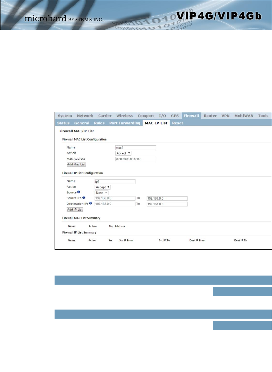
Image 4-8-5: Firewall > MAC-IP List
4.8.5 Firewall > MAC-IP List
MAC List configuration can be used to control which physical LAN devices can access the ports on the
VIP4G, by restricting or allowing connections based on the MAC address. IP List configuration can be used
to define who or what can access the VIP4G, by restricting or allowing connections based on the IP
Address/Subnet.
MAC-IP List can be used alone or in combination with LAN to WAN/4G Access Control to provide secure
access to the physical ports of the VIP4G.
Firewall MAC List Configuration
Rule Name
The Rule Name field is required to give the rule a convenient name for
reference. Each rule must have a unique name, up to 10 characters in
length.
Values (10 chars)
MAC_List
MAC Address
Specify the MAC Address to be added to the list. Must be entered in the
correct format as seen above. Not case sensitive. Values (MAC Address)
00:00:00:00:00:00

© Microhard Systems Inc. 129
4.0 Configuration
Firewall MAC List Configuration (Continued)
Action
The Action is used to define how the rule handles the connection request.
ACCEPT will allow a connection, while REJECT (error) and DROP (quietly
dropped), will refuse connections.
Values (selection)
ACCEPT
DROP
REJECT
Firewall IP List Configuration
Rule Name
The Rule Name field is required to give the rule a convenient name for
reference. Each rule must have a unique name, up to 10 characters in
length.
Values (10 chars)
IP_List
Source Address
Match incoming traffic from the specified source IP range. Boxes accept
single IP Addresses without network masks, example: 192.168.1.0 to
192.168.1.255 represents all IP Addresses in the 192.168.1.0/24 network.
(Put same IP in both boxes for a single IP match.)
Values (IP Address)
192.168.0.0 to
192.168.0.0
Action
The Action is used to define how the rule handles the connection request.
ACCEPT will allow a connection, while REJECT (error) and DROP (quietly
dropped), will refuse connections.
Values (selection)
ACCEPT / DROP / REJECT
Destination Address
Match incoming traffic from the specified destination IP range. Boxes
accept single IP Addresses without network masks, example: 192.168.1.0
to 192.168.1.255 represents all IP Addresses in the 192.168.1.0/24
network. (Put same IP in both boxes for a single IP match.)
Values (IP Address)
192.168.0.0 to
192.168.0.0
Source
Enter the specific zone that the IP List will apply to, 4G (Cellular), WAN ,
LAN (Ethernet, WiFi) or None (both). Values (Selection)
LAN / WAN / / WIFI / 4G /
NONE
© Microhard Systems Inc. 130
4.0 Configuration
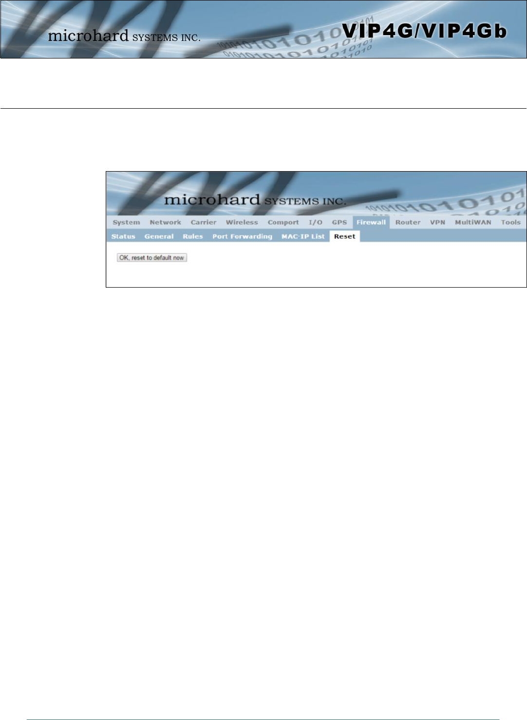
Image 4-8-6: Firewall > Reset to Defaults
4.8.6 Firewall > Reset
To reset the firewall back to default settings and erase all rules, port forwards, and IP/MAC lists, use the
reset button see below:
© Microhard Systems Inc. 131
4.0 Configuration
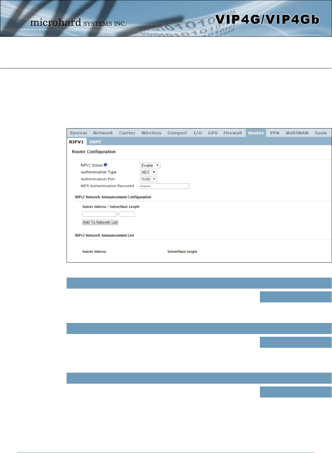
Image 4-9-1: Router > RIPv2
4.9 Router
4.9.1 Router > RIPV2
The VIP4G is capable of providing and participating in RIPv2 (Routing Information Protocol v2), to
exchange routing information from attached devices. Static routes can also be added in the Network >
Routes menu.
RIPV2 Status
Enable or disable RIPV2 routing on the VIP4G. If enabled the VIP4G will
exchange routing information on the specified (interfaces) attached
networks.
Values (selection)
Enable / Disable
Authentication Type / Port / Password
Enable MD5 authentication on for the RIPV2 protocol. Also select the port
used for RIPV2, and the required password. Values (selection)
None
MD5
RIPV2 Network Announcement Configuration
Each attached network that is to participate with the RIPV2 exchange must
be specified here. Once added they participating networks are shown in the
list.
Values (Subnet/Length))
(no default)
© Microhard Systems Inc. 132
4.0 Configuration
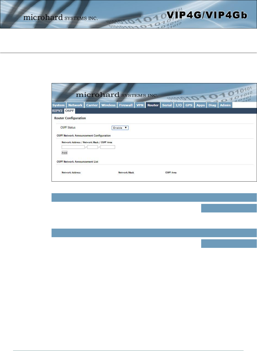
Image 4-9-2: Router > OSPF
4.9.2 Router > OSPF
The VIP4G is also capable of providing and participating in OSPF (Open Shortest Path First), to exchange
routing information from attached devices. Static routes can also be added in the Network > Routes menu.
OSPF Status
Enable or disable OSPF routing on the VIP4G. If enabled the VIP4G will
exchange routing information on the specified (interfaces) attached
networks.
Values (selection)
Enable / Disable
OSPF Network Announcement Configuration
Each attached network that is to participate with the OSPF exchange must
be specified here. Once added they participating networks are shown in the
list.
Values (Subnet/Length))
(no default)
© Microhard Systems Inc. 133
4.0 Configuration
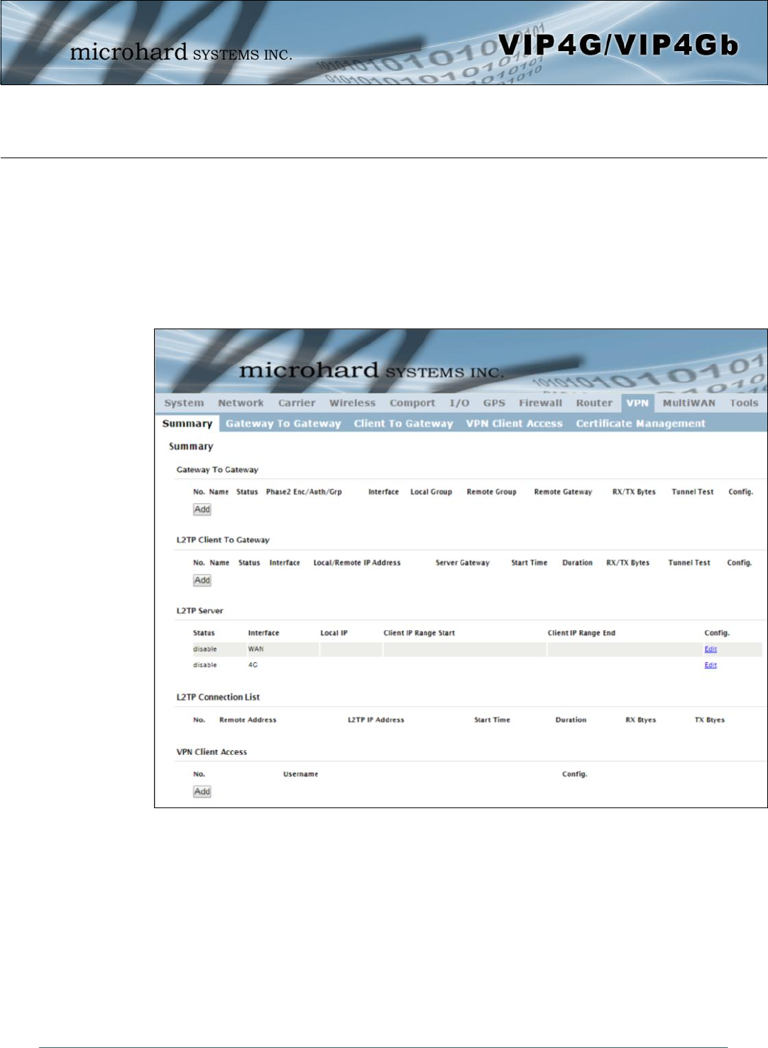
Image 4-10-1: VPN > Summary
4.10 VPN
4.10.1 VPN > Summary
A Virtual Private Network (VPN) may be configured to enable a tunnel between the VIP4G and a remote
network.. The VIP4G supports VPN IPsec Gateway to Gateway (site-to-site) tunneling, meaning you are
using the VIP4G to connect a tunnel to network with VPN capabilities (Another VIP4G or VPN capable
device). The VIP4G can also operate as a L2TP Server, allowing users to VPN into the unit from a remote
PC, and a L2TP Client.
© Microhard Systems Inc. 134
4.0 Configuration
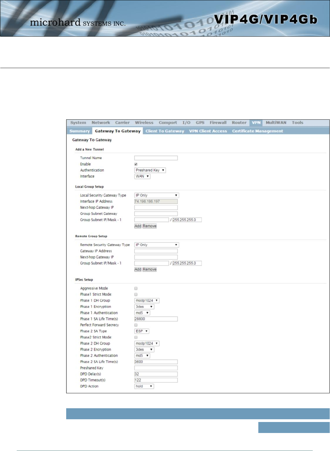
Image 4-9-2: VPN > Gateway to Gateway
4.9.2 VPN > Gateway To Gateway (Site-to-Site)
A Gateway to Gateway connection is used to create a tunnel between two VPN devices such as
an VIP4G and another device (another VIP4G or Cisco VPN Router or another vendor…). The
local and remote group settings will need to be configured below to mirror those set on the other
VPN device.
Tunnel Name
Enter a name for the VPN Tunnel. Up to 16 different tunnels can be
created, each requiring a unique name. Values (chars)
tunnel1
© Microhard Systems Inc. 135
4.0 Configuration
Local Group Setup
Interface IP Address
Displays the IP address of the VIP4G, which is the local VPN Gateway. Values (IP Address)
Current IP Address
Next-hop Gateway IP
Next-hop Gateway means the next-hop gateway IP address for the local or
remote gateway participant's connection to the public network. Values (IP Address)
(no default)
Enable
Used to enable (checked) is disable (unchecked) the VPN tunnel. Values (checkbox)
Enable (Checked)
Local Security Gateway Type
Specify the method for identifying the router to establish the VPN tunnel.
The Local Security Gateway is on this router; the Remote Security
Gateway is on the other router. At least one of the routers must have either
a static IP address or a dynamic IP with server id to make a connection.
Values (selection)
IP Only
IP + Server ID
Dynamic IP + Server ID
IP Only: Choose this option if this router has a static WAN IP address. The WAN IP address appears
automatically. For the Remote Security Gateway Type, an extra field appears. If you know the IP address
of the remote VPN router, choose IP Address, and then enter the address.
IP + Server ID: Choose this option if this router has a static WAN IP address and a server id. The WAN IP
address appears automatically. For the Remote Security Gateway Type, an extra field appears. If you
know the IP address of the remote VPN router, choose IP Address, and then enter the address.
Dynamic IP + Server ID: Choose this option if this router has a dynamic IP address and a server id
(available such as @microhard.vpn). Enter the server id to use for authentication. The server id can be
used only for one tunnel connection.
Server ID
This option appears when the Local Security Gateway Type specifies that
the Server ID is required for the connection. The Server ID must be in the
format @name, where name can be anything. Both routers must know
each others names to establish a connection.
Values (IP Address)
(no default)
Group Subnet IP
Define the local network by specifying the local subnet. The local and
remote routers must use different subnets. Values (IP Address)
(no default)
© Microhard Systems Inc. 136
4.0 Configuration
Subnet IP Address
Define the remote network by specifying the local subnet. Values (IP Address)
(no default)
Subnet Mask
Specify the subnet mask of the remote network address. Values (IP Address)
255.255.255.0
Group Subnet Gateway
Enter the Gateway for the local group network. Values (IP Address)
(no default)
Remote Group Setup
Gateway IP Address
If the remote VPN router has a static IP address, enter the IP address of
the remote VPN Gateway here. Values (IP Address)
(no default)
Group Subnet Mask
Specify the subnet mask of the local network address. Values (IP Address)
255.255.255.0
Remote Security Gateway Type
Specify the method for identifying the router to establish the VPN tunnel.
The Local Security Gateway is on this router; the Remote Security
Gateway is on the other router. At least one of the routers must have either
a static IP address or a dynamic IP with server id to make a connection.
(See Local Group Setup for details)
Values (selection)
IP Only
IP + Server ID
Dynamic IP + Server ID
Server ID
This option appears when the Remote Security Gateway Type specifies
that the Server ID is required for the connection. The Server ID must be in
the format @name, where name can be anything. Both routers must know
each others names to establish a connection.
Values (IP Address)
(no default)
Next-hop Gateway IP
Next-hop Gateway means the next-hop gateway IP address for the local or
remote gateway participant's connection to the public network. Values (IP Address)
(no default)
© Microhard Systems Inc. 137
4.0 Configuration
Phase 1 SA Life Time
Select value to match the values required by the remote VPN router. Values
28800
Perfect Forward Secrecy (pfs)
Select value to match the values required by the remote VPN router. Values (selection)
Disable / Enable
Phase 1 Authentication
Select value to match the Phase 1 Authentication used by the remote VPN
router. Values (selection)
md5
sha1
Phase 1 Encryption
Select value to match the Phase 1 Encryption type used by the remote
VPN router. Values (selection)
3des
aes
aes128
aes256
IPsec Setup
Phase 1 DH Group
Select value to match the values required by the remote VPN router. Values (selection)
modp1024
modp1536
modp2048
Phase 2 DH Group
Select value to match the values required by the remote VPN router. Values (selection)
modp1024
modp1536
modp2048
Phase 2 Encryption
Select value to match the Phase 1 Encryption type used by the remote
VPN router. Values (selection)
3des
aes
aes128
aes256
© Microhard Systems Inc. 138
4.0 Configuration
Phase 2 Authentication
Select value to match the Phase 1 Authentication used by the remote VPN
router. Values (selection)
md5
sha1
Phase 2 SA Life Time
Select value to match the values required by the remote VPN router. Values
3600
Preshared Key
Set the Preshared Key required to authenticate with the remote VPN
router. Values (characters)
password
DPD Delay(s)
Dead Peer Detection is used to detect if there is a dead peer. Set the DPD
Delay (seconds), as required. Values (seconds)
32
DPD Timeout(s)
Set the DPD (Dead Peer Detection) Timeout (seconds), as required. Values (seconds)
122
DPD Action
Set the DPD action, hold or clear, as required. Values (seconds)
Hold
Clear
© Microhard Systems Inc. 139
4.0 Configuration
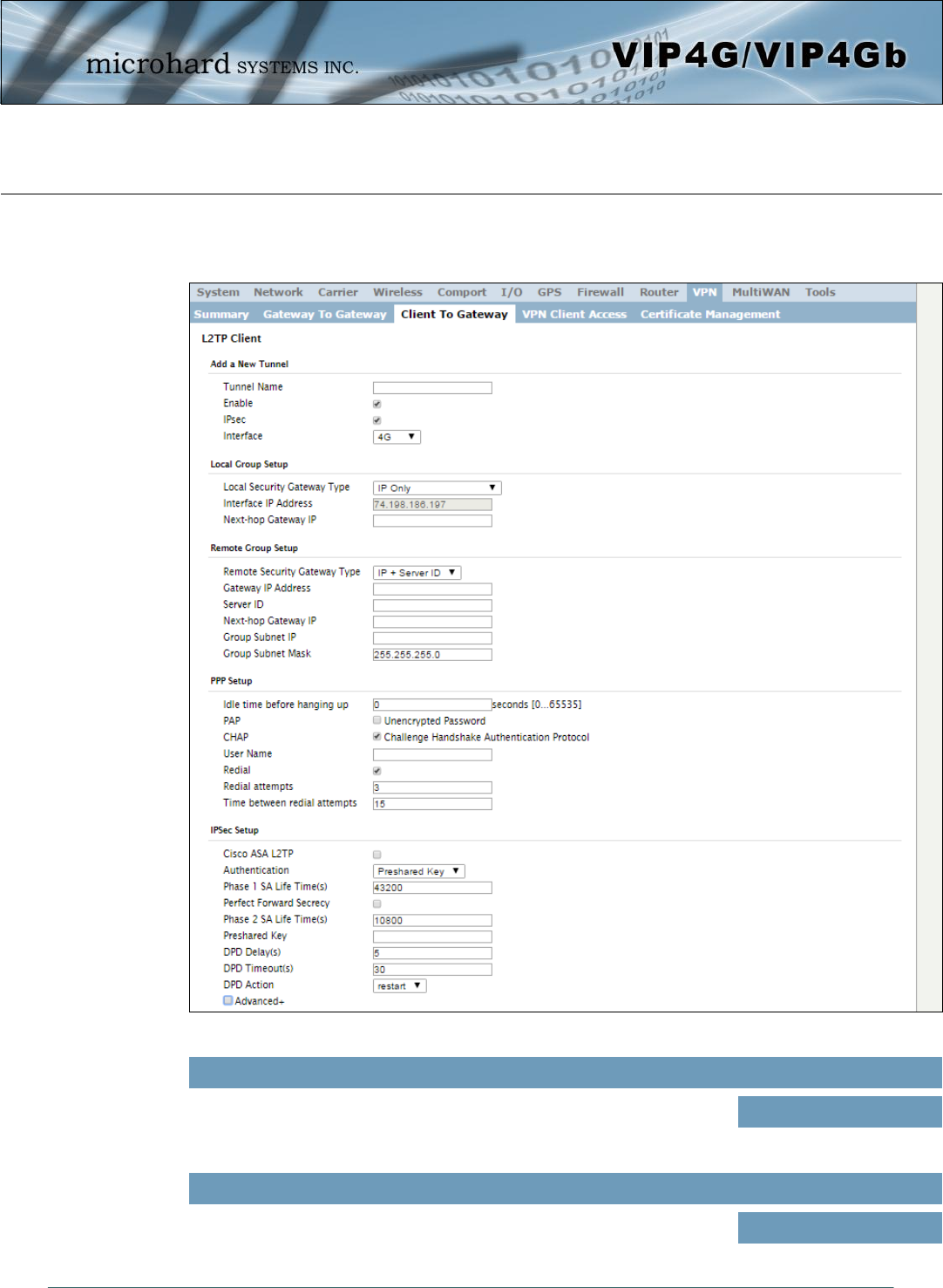
Image 4-10-3: VPN > Client to Gateway
4.10.3 VPN > Client To Gateway (L2TP Client)
The VIP4G can operate as a L2TP Client, allowing a VPN connection to be made with a L2TP Server.
Tunnel Name
Enter a name for the VPN Tunnel. Up to 16 different tunnels can be
created, each requiring a unique name. Values (chars)
tunnel1
Enable
Used to enable (checked) is disable (unchecked) the VPN tunnel. Values (checkbox)
Enable (Checked)
© Microhard Systems Inc. 140
4.0 Configuration
Local Interface IP Address
This will show the WAN or 4G IP Address used for the L2TP Interface. Values (IP Address)
Current IP
Remote Gateway IP Address
Enter the IP Address of the Remote Gateway that you wish to establish a
connection with. Values (IP Address)
none
Remote Server ID
Some servers require that you know the Server ID as well as the IP
address. Enter the Server ID of the remote router here. Values
none
Remote Subnet IP
In order to communicate with the devices on the other side of the tunnel,
the VIP4G must know which data to pass through the tunnel, to do this
enter the Remote Subnet network IP address here.
Values (IP Address)
none
Remote Subnet Mask
Enter the Remote Subnet Mask Values (IP Address)
none
Idle time before hanging up
Enter the Idle time (in seconds) to wait before giving up the PPP
connection. The default is 0, which means the time is infinite. (0—65535) Values (seconds)
0
Username
Enter the Username Values (chars)
0
Preshared Key
The preshared key is required to connect to the L2TP Server. Values (chars)
0
IPSec Setup - See previous sections for additional info.
© Microhard Systems Inc. 141
4.0 Configuration
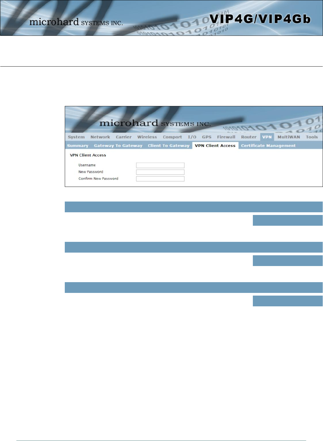
Image 4-10-4: VPN > VPN Client Access
4.10.4 VPN > VPN Client Access
For VPN L2TP Server operation, users will be required to provide a username and password. Use VPN
Client Access to set up the required users.
Username
Enter a username for the user being set up.
Values (characters)
New Password
Enter a password for the use. Values (characters)
Confirm New Password
Enter the password again, the VIP4G will ensure that the password match. Values (IP Address)
© Microhard Systems Inc. 142
4.0 Configuration
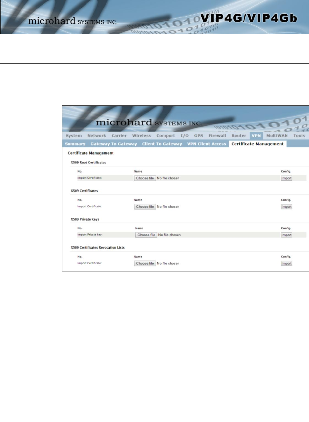
Image 4-10-5: VPN > Certificate Management
4.10.5 VPN > Certificate Management
When using the VPN features of the VIP4G, it is possible to select X.509 for the Authentication Type. If that
is the case, the VIP4G must use the required x.509 certificates in order to establish a secure tunnel
between other devices. Certificate Management allows the user a place to manage these certificates.
© Microhard Systems Inc. 143
4.0 Configuration
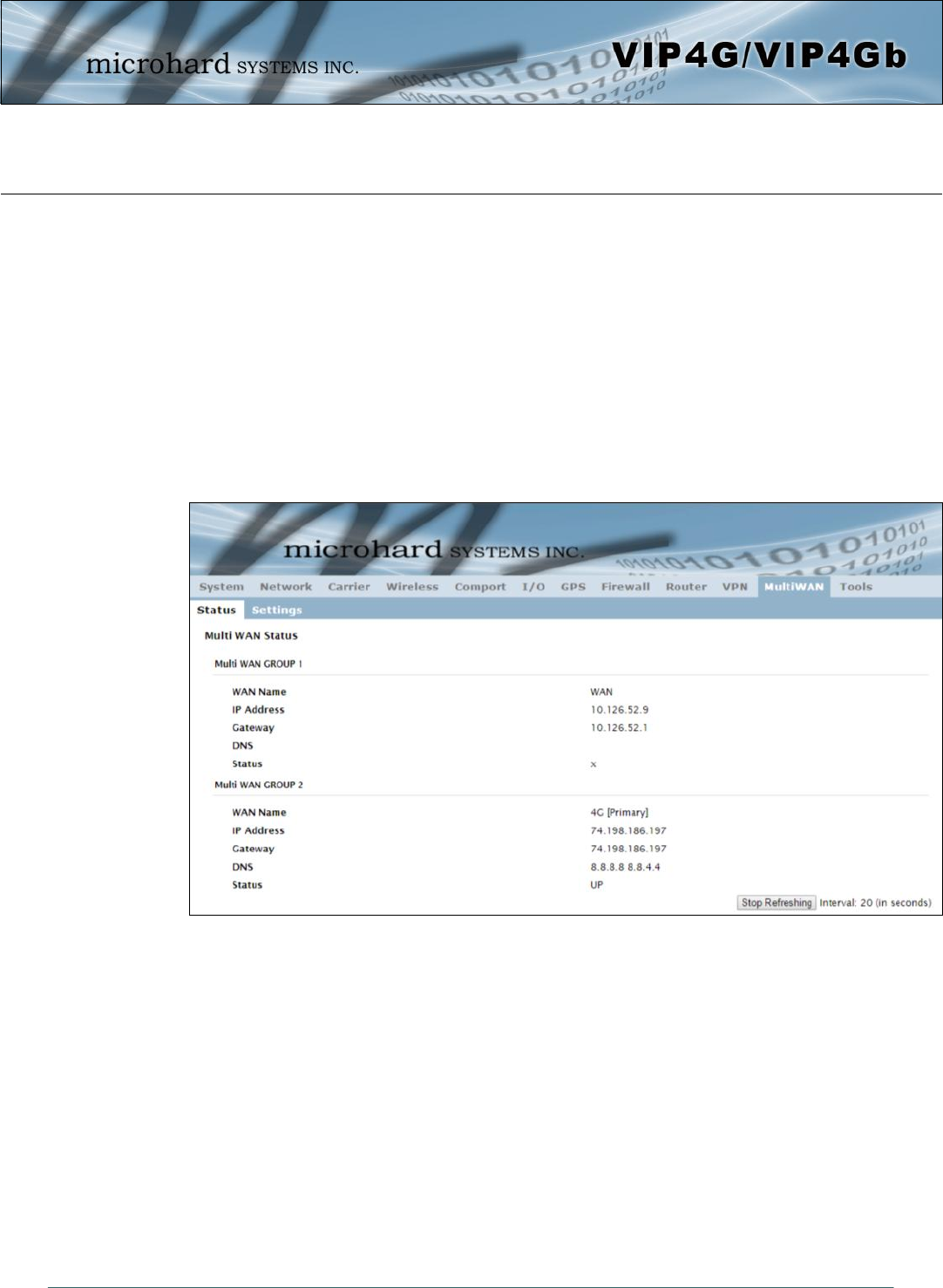
Image 4-10-1: MultiWAN > Status
4.11 MultiWAN
4.11.1 MultiWAN > Status
The VIP4G is capable of having 2 WAN connections, one connected to the physical WAN port on the
VIP4G and the Cellular WAN connection to the wireless carrier. The MultiWAN section allows a user to
define how traffic uses these WAN’s.
The main purpose of the MultiWan feature is to use one network for a primary connection, such as a local,
wired ISP for broadband access, and if that connection fails or is offline, the VIP4G can automatically
switch to an alternate network connection such as the 4G/Cellular connection.
The Status menu gives an overview of both WAN connections and their configuration. WAN group 1 is the
wired WAN and WAN group 2 is the 4G/Cellular connection to a wireless carrier.
© Microhard Systems Inc. 144
4.0 Configuration
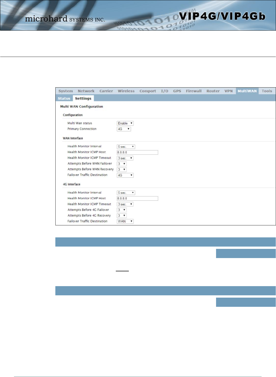
Image 4-10-2: MultiWAN > Settings
4.10.2 MultiWAN > Settings
The following section describes the parameters required for MultiWan for failover purposes. The
configuration for each interface in identical, so will only be described once.
Multi Wan status
Enable or disable the MultiWan service on the VIP4G.
To use MultiWAN, the WAN (wired) must be configured as independent in
the Network > WAN settings and/or the Wireless must be set to Client &
bound to the WIFI interface.
Values (selection)
Enable / Disable
Primary Connection
Define which connection is the primary network/internet connection for the
VIP4G. Normally this is the wired WAN connection to an ISP.
Values (selection)
WAN / 4G / WIFI
© Microhard Systems Inc. 145
4.0 Configuration
Health Monitor ICMP Timeout
This is the amount of time the Health Monitor will wait for a response from
the ICMP Host. Values (selection)
1, 2, 3, 4, 5, 10 (seconds)
Attempts Before WAN Failover
This is the number of attempts the VIP4G will attempt to reach the IMCP
host before going into failover and switching WAN interfaces. Values (selection)
1, 3, 5, 10, 15, 20
Attempts Before WAN Recovery
The VIP4G will continue to monitor the failed interface, even after failover
has occurred. This defines the number of successful attempts required
before recovering the failed interface.
Values (selection)
1, 3, 5, 10, 15, 20
Failover Traffic Destination
Select the interface to use once failover has occurred. Values (selection)
4G, WAN, Disable
Health Monitor ICMP Host
This is the IP Address or domain name of a valid reachable host that can
be used to determine link health. Values (Address)
8.8.8.8
Health Monitor Interval
This is the frequency at which the VIP4G will send ICMP packets to the
defined host to determine if the interface has failed. Values (selection)
5,10,20,30,60,120(sec.)
Disable
© Microhard Systems Inc. 146
4.0 Configuration
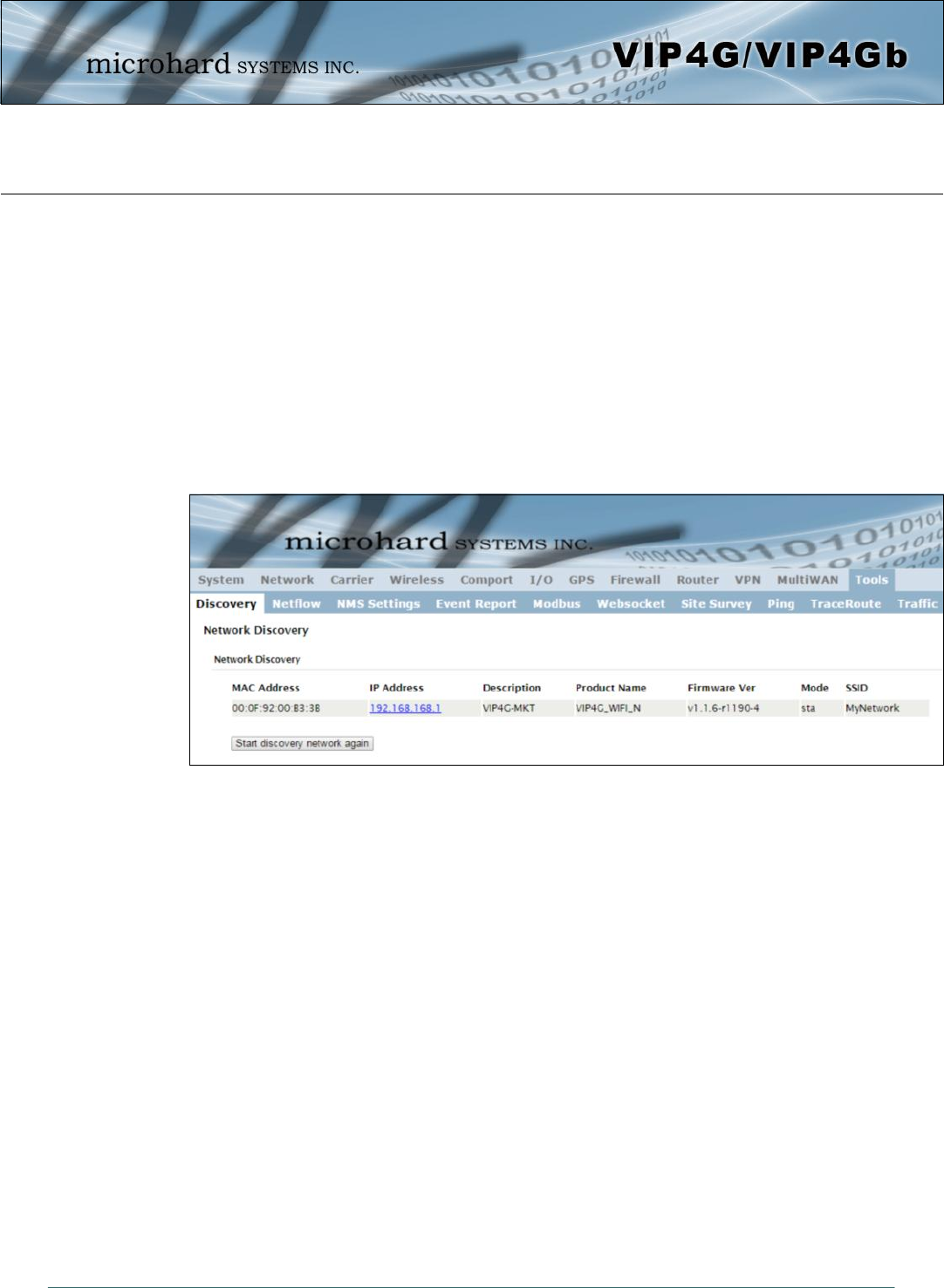
Image 4-12-1: Tools > Discovery
4.12 Tools
4.12.1 Tools > Discovery
Network Discovery
The Network discovery tool allows the VIP4G to send a broadcast to all VIP4G/VIP Series units on the
same network. Other units on the network will respond to the broadcast and report their MAC address, IP
address (With a hyperlink to that units WebUI page), description, firmware version, operating mode, and
the SSID (regardless of whether it was set to broadcast or not).
The discovery service can be a useful troubleshooting tool and can be used to quickly find and indentify
other units on the network. It can be disabled from the Network > sdpServer menu.
To begin, click the Start discovery network again button, the VIP4G will send out a broadcast message,
and will report back, by populating the network discovery screen as seen above. This will detect any VIP4G
or Microhard enabled devices on the local broadcast domain, regardless of the IP address or subnet. Once
devices are found, and if on a accessible subnet, the IP Address link can be used to automatically open a
web browser WebUI session with that unit.
© Microhard Systems Inc. 147
4.0 Configuration
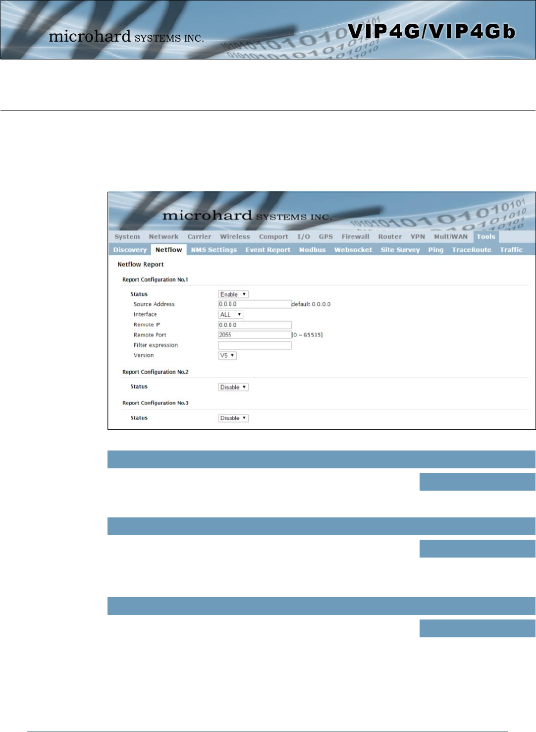
Image 4-12-2: Tools > Netflow Report
4.12.2 Tools > Netflow Report
The VIP4G can be configured to send Netflow reports to up to 3 remote systems. Netflow is a tool that
collects and reports IP traffic information, allowing a user to analyze network traffic on a per interface basis
to identity bandwidth issues and to understand data needs. Standard Netflow Filters can be applied to
narrow down results and target specific data requirements.
Status
Enable / Disable Netflow Reporting. Values (selection)
Disable / Enable
Interface
Select between WAN ,4G/Cellular and LAN interfaces, or capture data from
all interfaces. Values (selection)
LAN / WAN / 4G / ALL
Source Address
The Source Address is the IP Address, of which data is to be collected and
analyzed. The default of 0.0.0.0 will collect and report information about all
addresses connected to the interface selected below.
Values (IP Address)
0.0.0.0
© Microhard Systems Inc. 148
4.0 Configuration
Remote Port
Enter the Remote Port number. Values (IP Address)
0
Filter expression
Filter expression selects which packets will be captured. If no expression is
given, all packets will be captured. Otherwise, only packets for which
expression is `true' will be captured. Example: tcp&&port 80
The “tcpdump” manual, available on the internet provides detailed expression syntax.
Values (chars)
(no default)
Remote IP
The Remote IP is the IP Address of the NetFlow collector where the flow
reports are be sent. Values (IP Address)
0.0.0.0
Version
Select the Netflow version format to use. V1, 5 and 7 are supported. Values (selection)
V1 / V5 / V7
© Microhard Systems Inc. 149
4.0 Configuration
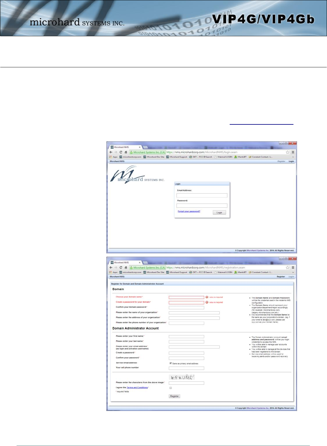
Image 4-12-3: NMS Registration
4.12.3 Tools > NMS Settings
The Microhard NMS is a no cost server based monitoring and management service offered by Microhard
Systems Inc. Using NMS you can monitor online/offline units, retrieve usage data, perform backups and
centralized upgrades, etc. The following section describes how to get started with NMS and how to
configure the VIP4G to report to NMS.
To get started with NMS, browse to the Microhard NMS website, nms.microhardcorp.com, click on the
register button in the top right corner to register for a Domain (profile), and set up a Domain Administrator
Account.
© Microhard Systems Inc. 150
4.0 Configuration
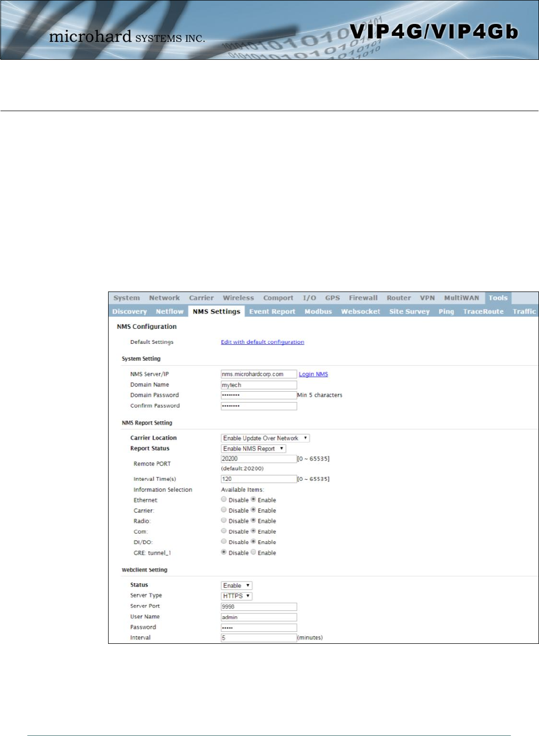
Image 4-12-4: NMS Settings
Domain Name: A logical management zone for 3G or 4G devices will report to on NMS, the logged data
is separated from any other users that are using NMS. The Domain Name is required in every 3G or 4G
device for it to report to right zone. Under this user domain, one can create and manage sub-domain. The
sub-domain can only be created by the domain administrator, NOT by the NMS subscription page.
Domain Password: This password is used to prevent misuse of the domain. This needs to be entered
into each 3G or 4G device for it to report to right zone.
Email Address: The email address entered here will be the login username. During the registration stage,
a confirmation email will be sent by the NMS system for verification and confirmation to activate your
account.
Once confirmed, this account will be the administrator of the domain. The administrator can manage sub-
domain and user accounts that belong to this domain.
Once NMS has been configured, each VIP4G must be configured to report into NMS.
© Microhard Systems Inc. 151
4.0 Configuration
Default Settings
The default Settings link will reset the configuration form to the default factory values. The form still needs
to be submitted before any changes will occur.
NMS Server/IP
The default server address for NMS is nms.microhardcorp.com. The NMS
can also be hosted privately, and if that is the case, enter the address here. Values (IP/Name)
nms.microhardcorp.com
Domain Name / Password
This is the domain name and password that was registered on the NMS
website, it must be entered to enable reporting to the NMS system. Values (chars)
default
Carrier Location
Enable or Disable location estimation via carrier connection. When
enabled, the VIP4G will consume some data to retrieve location information
from the internet.
Values (chars)
Disable/Enable
Remote Port
This is the port to which the UDP packets are sent, and the NMS system is
listening on. Ensure this matches what is configured on NMS. The default
is 20200.
Values (UDP Port#)
20200
Network Management System (NMS) Configuration
NMS Report Setting
Report Status
Enable or Disable UDP reporting of data to the NMS system. Values (chars)
Enable NMS Report
Disable NMS Report
Interval(s)
The Interval defines how often data is reported to NMS. The more often
data is reported, the more data is used, so this should be set according to a
user’s data plan. (0 to 65535 seconds)
Values (seconds)
300

© Microhard Systems Inc. 152
4.0 Configuration
Information Selection
The VIP4G can report information about the different interfaces it has. By
default the VIP4G is set to send information about the Carrier, such as
usage and RSSI. Statistical and usage data on the Radio (WiFi), Ethernet
and Serial interfaces can also be reported.
The more that is reported, the more data that is sent to the NMS system,
be aware of data plan constraints and related costs.
Values (check boxes)
Ethernet
Carrier
Radio
COM
DI / DO
Status
The Web Service can be enabled or disabled. This service is used to
remotely control the VIP4G. It can be used to schedule reboots, firmware
upgrade and backup tasks, etc.
Values (chars)
Disable/Enable
Server Port
This is the port where the service is installed and listening. This port should
be open on any installed firewalls. Values (Port#)
9998
Webclient Setting
Server Type
Select between HTTPS (secure), or HTTP server type. Values (chars)
HTTPS/ HTTP
Username / Password
This is the username and password used to authenticate the unit. Values (seconds)
admin/admin
Interval
The Interval defines how often the VIP4G checks with the NMS System to
determine if there are any tasks to be completed. Carrier data will be
consumed every time the device probes the NMS system.
Values (min)
60
© Microhard Systems Inc. 153
4.0 Configuration
Image 4-12-5: Tools > Event Report
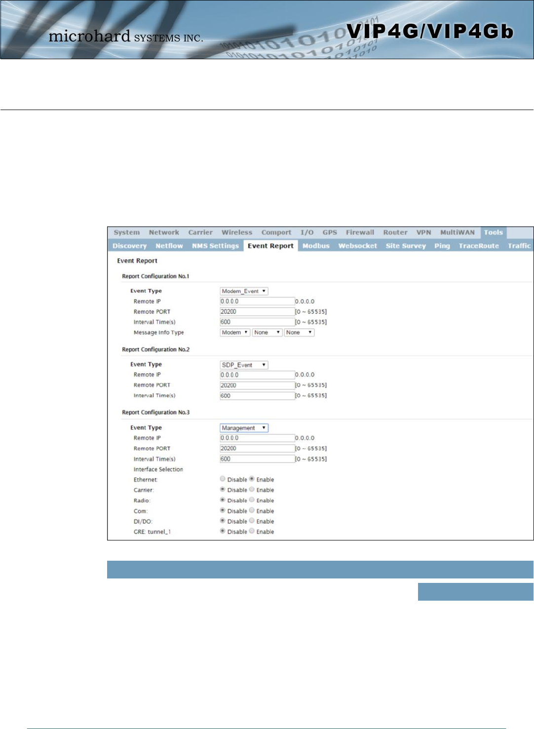
4.12.4 Tools > Event Report
4.12.4.1 Event Report > Configuration
Event Reporting allows the VIP4G to send periodic updates via UDP packets. These packets are
customizable and can be sent to up to 3 different hosts, and at a programmable interval. The event packet
can report information about the modem such as the hardware/ software versions, core temperature,
supply voltage, etc; carrier info such as signal strength (RSSI), phone number, RF Band; or about the WAN
such as if the assigned IP Address changes. All events are reported in binary.
Event Type
This box allows the selection of the type of event to be reported. The
default is disabled. If Modem_Event is selected, additional options appear
to the right and allow for customization of the event reported via Messages.
If Management is selected, additional check boxes appear below to select
the interfaces to report to the Microhard NMS system.
Values (selection)
Modem_Event
SDP_Event
Management
© Microhard Systems Inc. 154
4.0 Configuration
Remote IP
Enter the IP Address of a reachable host to send the UDP packets Values (IP Address)
0.0.0.0
Remote Port
Specify the UDP port number of the Remote IP Address.
*Default Port Numbers for Microhard NMS (20100 for modem events, 20200 for
Management)
Values (Port #)
20200
Interval Time(s)
This is the interval time in seconds, that the VIP4G will send the configured
UDP message to the Remote IP and Port specified. Values (seconds)
600
4.12.4.2 Event Report > Message Structure
Modem_event message structure
- fixed header (fixed size 20 bytes)
- Modem ID (uint64_t (8 bytes))
- Message type mask (uint8_t(1 byte))
- reserved
- packet length (uint16_t(2 bytes))
Note: packet length = length of fixed header + length of message payload.
Message type mask
Modem info - 2 bits
00 no
01 yes (0x1)
Carrier info - 2 bits
00 no
01 yes (0x4)
WAN Info - 2 bits
00 no
01 yes (0x10)
sdp_event message structure
- spd_cmd (1 byte(0x01))
- content length (1 byte)
- spd_package - same as spd response inquiry package format
Message Info Type
When Modem_Event is selected, up to three different payloads can be
selected. Values (seconds)
Modem
Carrier
WAN

© Microhard Systems Inc. 155
4.0 Configuration
4.12.4.3 Event Report > Message Payload
Modem info:
Content length - 2 BYTES (UINT16_T)
Modem name - STRING (1-30 bytes)
Hardware version - STRING (1-30 bytes)
Software version - STRING (1-30 bytes)
Core temperature - STRING (1-30 bytes)
Supply voltage - STRING (1-30 bytes)
Carrier info:
Content length - 2 BYTES (UINT16_T)
RSSI - 1 BYTE (UINT8_T)
RF Band - 2 BYTES (UINT16_T)
Service type - STRING (1-30 Bytes)
Channel number - STRING (1-30 Bytes)
SIM card number - STRING (1-30 Bytes)
Phone number - STRING (1-30 Bytes)
WAN Info:
Content length - 2 BYTES (UINT16_T)
IP address - 4 BYTES (UINT32_T)
DNS1 - 4 BYTES (UINT32_T)
DNS2 - 4 BYTES (UINT32_T)
Message Order:
Messages will be ordered by message type number.
For example,
If message type mask = 0x15, the eurd package will be equipped by header+modem information+carrier
information+wanip information.
If message type mask = 0x4, the eurd package will be equipped by header+carrier information.
If message type mask = 0x11, the eurd package will be equipped by header+modem infomation+wanip
infomation.

© Microhard Systems Inc. 156
4.0 Configuration
Image 4-12-6: Tools > Modbus Configuration
4.12.5 Tools > Modbus
4.12.5.1 Modbus > TCP Modbus
The VIP4G can be configured to operate as a TCP/IP or Serial (COM) Modbus slave and respond to
Modbus requests and report various information as shown in the Data Map.
Status
Disable or enable the Modbus service on the VIP4G. Values (selection)
Disable Service
Enable Service
TCP Mode Status
Disable or enable the Modbus TCP Connection Service on the VIP4G. Values (selection)
Disable
Enable
© Microhard Systems Inc. 157
4.0 Configuration
Port
Specify the Port in which the Modbus TCP service is to listen and respond
to polls. Values (Port #)
502
Active Timeout(s)
Define the active timeout in seconds. Values (seconds)
30
Slave ID
Each Modbus slave device must have a unique address, or Slave ID. Enter
this value here as required by the Modbus Host System. Values (value)
1
Coils Address Offset
Enter the Coils Address offset as required by the Master. Values (value)
0
Input Address Offset
Enter the Input Address offset as required by the Master. Values (value)
0
Register Address Offset
Enter the Register Address offset as required by the Master. Values (value)
0
Master IP Filter Set
It is possible to only accept connections from specific Modbus Master IP’s,
to use this feature enable the Master IP Filter and specify the IP Addresses
in the fields provided.
Values (selection)
Disable / Enable
© Microhard Systems Inc. 158
4.0 Configuration
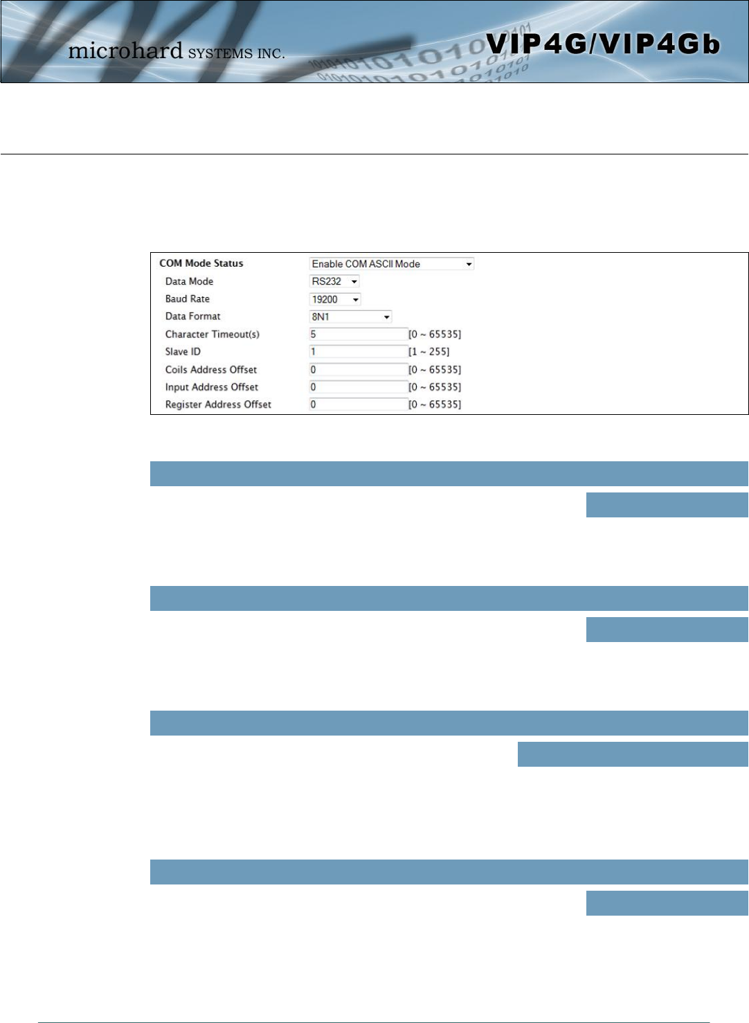
4.12.5.2 Modbus > COM (Serial) Modbus
The VIP4G can also participate in serial based Modbus, to configure and view the serial Modbus settings,
the COM1 port must first be disabled in the Comport > Settings menu. Only the settings that are different
from TCP Modbus will be discussed.
COM Mode Status
Disable to select the Serial (COM) mode for the Modbus service. In RTU
mode, communication is in binary format and in ASCII mode,
communication is in ASCII format.
Values (selection)
Disable
Enable COM ASCII Mode
Enable COM RTU Mode
Data Mode
Determines which (rear of unit) serial interface shall be used to connect to
external devices: RS232, RS485, or RS422. This option applies only to
COM1. When an interface other than RS232 is selected, the DE9 port will
be inactive.
Values (selection)
RS232
RS485
RS422
Baud Rate
The serial baud rate is the rate at which the modem is to
communicate with the attached local serial device. Values (selection (bps))
921600
460800
230400
115200
14400
9600
7200
4800
57600
38400
28800
19200
3600
2400
1200
600
300
Data Format
This setting determines the format of the data on the serial port.
The default is 8 data bits, No parity, and 1 Stop bit. Values (selection)
8N1
8N2
8E1
7E1
7O1
7E2
7O2
8O1
7N1
7N2
Image 4-12-7: Tools > Modbus Serial Configuration
© Microhard Systems Inc. 159
4.0 Configuration
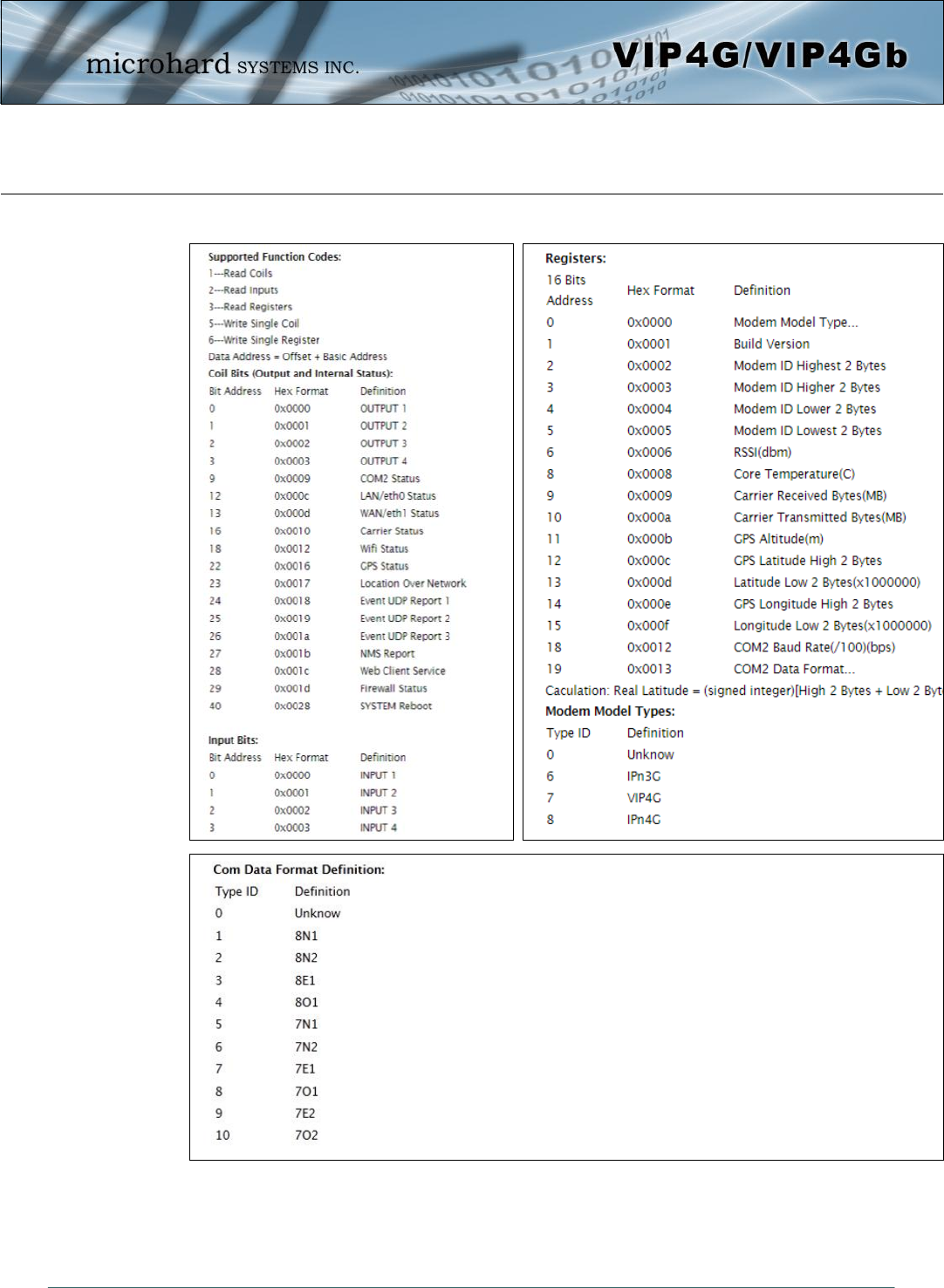
4.12.5.3 Modbus > Modbus Data Map
Image 4-12-8: Tools > Modbus Data Map
© Microhard Systems Inc. 160
4.0 Configuration
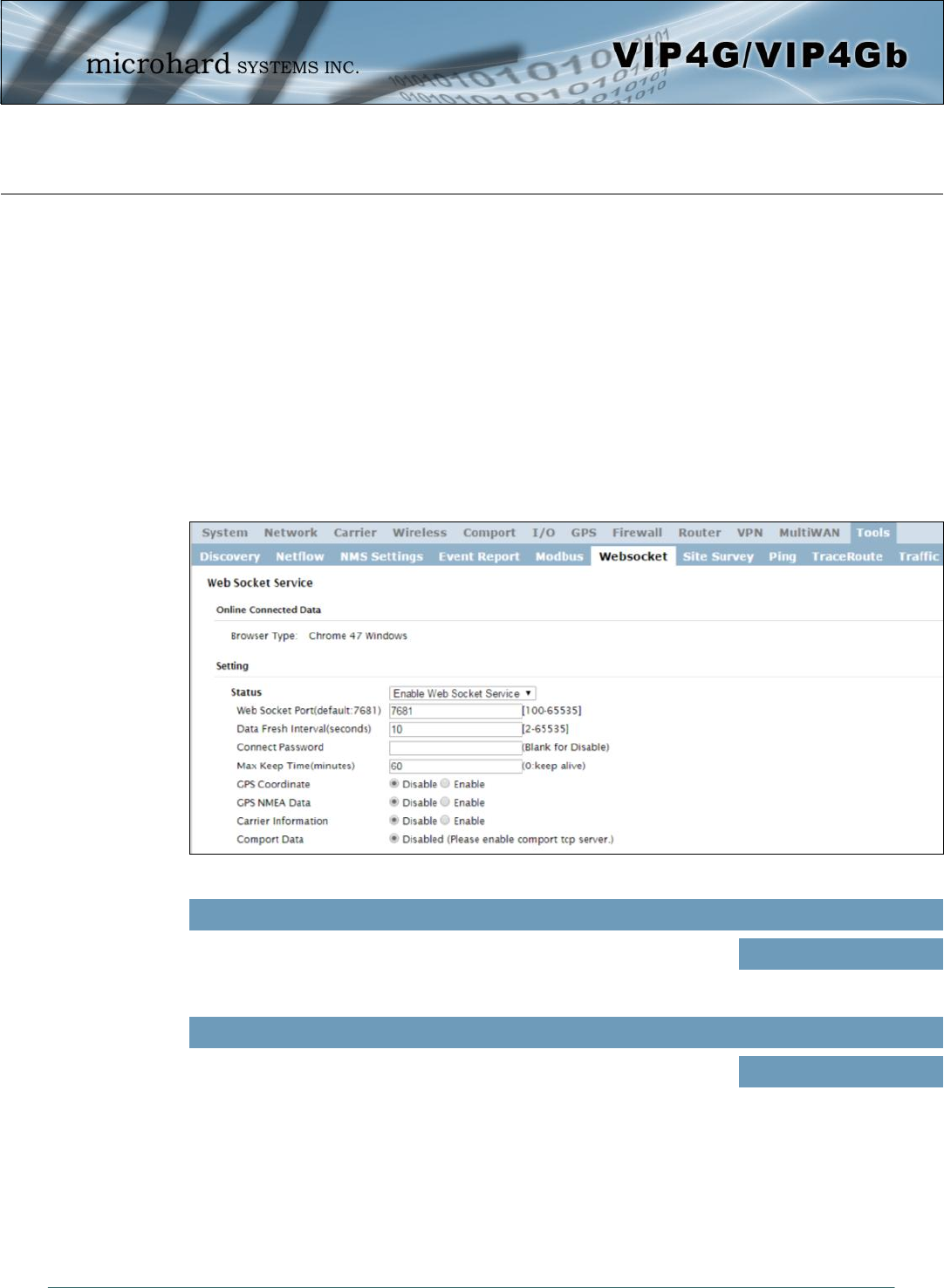
Image 4-12-9: Tools > Web Socket Service
4.12.6 Tools > Websocket
The Websocket service is a feature of HTML5.0 or later. Web Socket is designed to be implemented in
web browsers and web servers to allow XML scripts to access the HTML web service with a TCP socket
connection.
It is mainly used for two purposes:
refreshing page information without refreshing the entire page to reduce network stream.
to integrate internet applications with xml to get required information in real time.
Currently we provide four types of information as configured:
GPS Coordinate Information
GPS NMEA Data
Carrier Information
Comport Data
Status
Enable or disable the web socket service in the VIP4G. Values (selection)
Enable / Disable
Web Socket Port
Enter the desired web socket TCP port number. The default is 7681, and
the valid range is 100 to 65535. Values (TCP port)
7681

© Microhard Systems Inc. 161
4.0 Configuration
Data Fresh Intervals
Enter in the time at which data is to be refreshed. The default is 10
seconds, the valid range is 2 to 65535 seconds. Values (seconds)
10
Connect Password
For added security a password can be required to connect to the web
socket service. To disable, leave this field blank. The default is disabled. Values
(blank)
Max Keep Time
This field determines how long the web socket is open once started/
enabled. The default is 60 mins, a value of zero means the service with
continue to run indefinitely.
Values (minutes)
60
GPS Coordinate
If enabled the VIP4G will report GPS coordinate data to the websocket. Values (selection)
Disable / Enable
GPS NMEA Data
If enabled the VIP4G will report GPS NMEA data to the websocket. Values (selection)
Disable / Enable
Carrier Information
If enabled the VIP4G will report carrier information to the websocket. Values (selection)
Disable / Enable
Comport Data
If enabled, and the COM1 port is configured for TCP Server, the comport
data will be reported to the web socket. Values (selection)
Disable / Enable
© Microhard Systems Inc. 162
4.0 Configuration
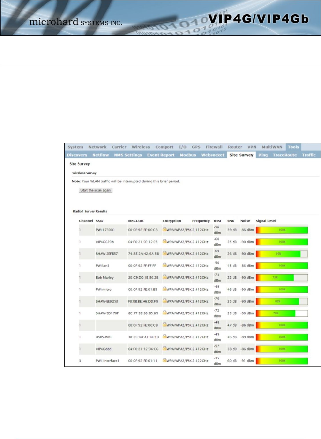
Image 4-12-10: Tools > Site Survey
4.12.7 Tools > Site Survey
Wireless Survey
The Wireless Survey feature will scan the available wireless channels for any other 802.11 wireless
networks in proximity to the VIP4G. The Survey will display the Channel number the other networks are
operating on, the MAC address, Encryption Type, Frequency and general signal level and quality
information. This can be useful for finding available networks, or troubleshooting connection and sensitivity
problems. If there are other networks operating on the same frequency, or a channel close to the one
chosen, it can then be decided to try to use another channel.
© Microhard Systems Inc. 163
4.0 Configuration
Image 4-12-11: Tools > Ping
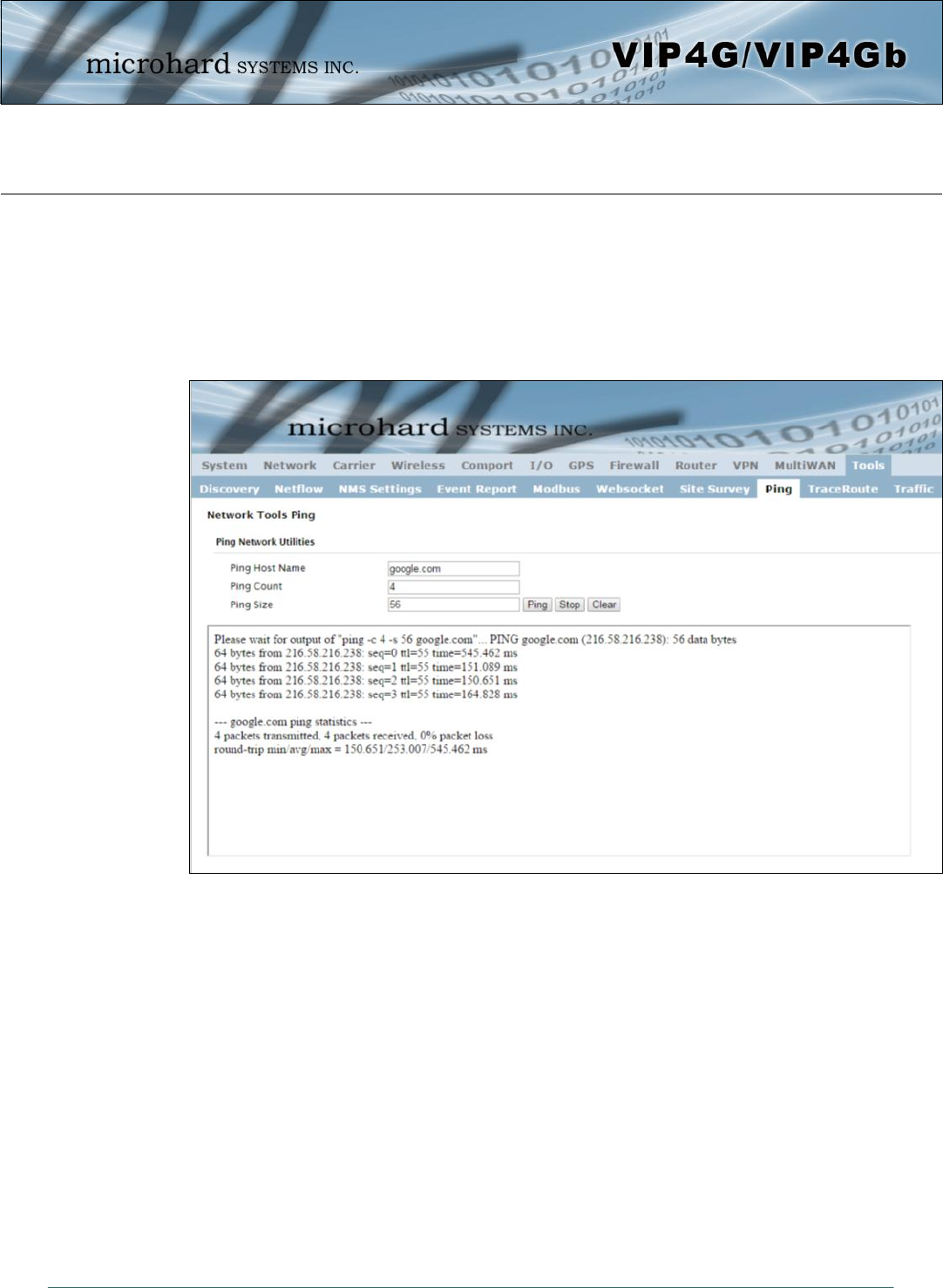
4.12.8 Tools > Ping
Network Tools Ping
The Network Tools Ping feature provides a tool to test network connectivity from within the VIP4G unit. A
user can use the Ping command by entering the IP address or host name of a destination device in the
Ping Host Name field, use Count for the number of ping messages to send, and the Packet Size to modify
the size of the packets sent.
© Microhard Systems Inc. 164
4.0 Configuration
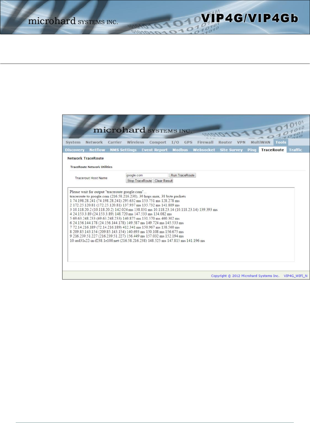
Image 4-12-12: Tools > TraceRoute
4.12.9 Tools > TraceRoute
Network TraceRoute
The Trace Route command can be used to provide connectivity data by providing information about the
number of hops, routers and the path taken to reach a particular destination.
© Microhard Systems Inc. 165
4.0 Configuration
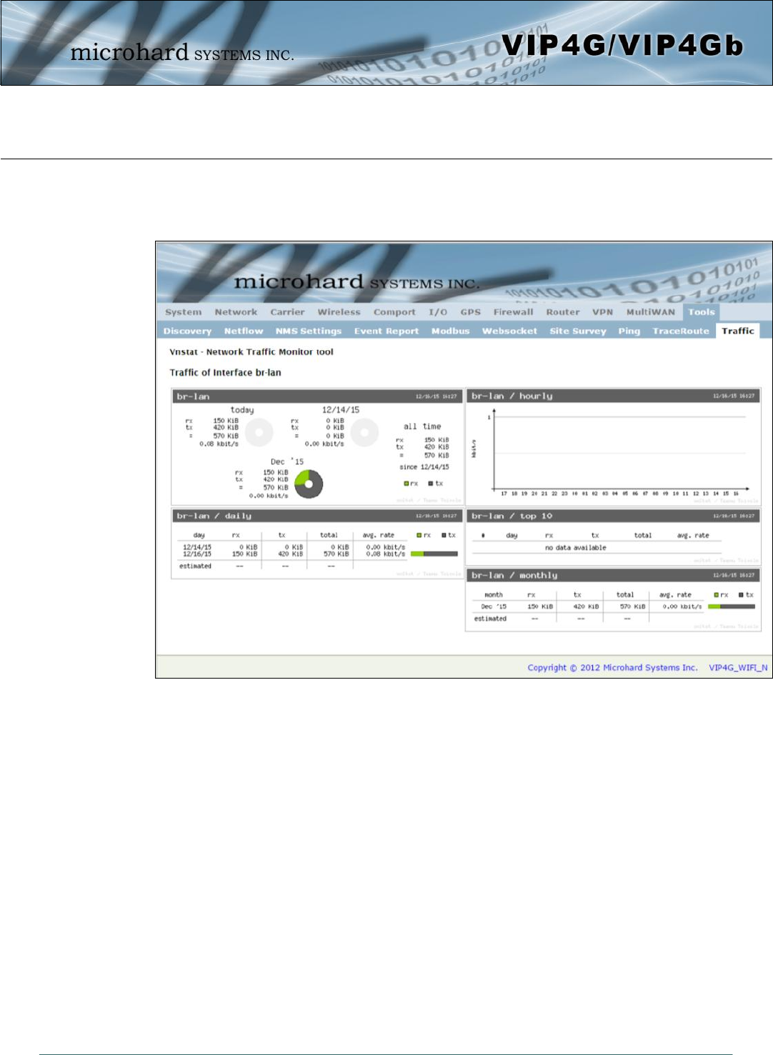
Image 4-12-13: Tools > Traffic
4.12.10 Tools > Traffic
The Traffic menu shows a graphical display of the LAN traffic by day and month. It can be used to
determine when there are high and low periods of LAN traffic over a period of time.
© Microhard Systems Inc. 166
5.0 AT Command Line Interface
5.1 AT Command Overview
AT Commands can be issued to configure and manage the VIP4G, serial port (Serial), or by TCP/IP
(telnet).
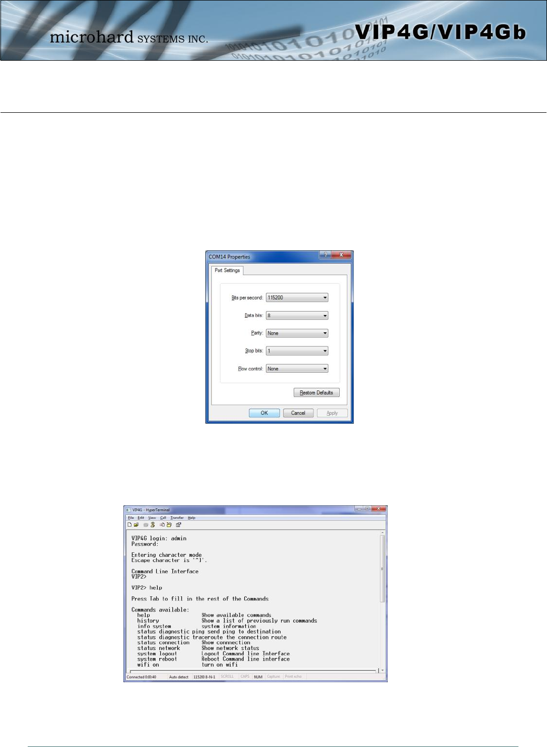
5.1.1 Serial Port
To connect and access the AT Command interface on the VIP4G, a physical connection must be made on
the RS232 DB9 serial port labeled ‘Serial’. A terminal emulation program (Hyperterminal, Tera Term,
ProComm, Putty etc) can then be used to communicate with the VIP4G.
Image 5-1: Serial Port Settings
Default Settings:
Baud rate: 115200
Data bits: 8
Parity: None
Stop Bits: 1
Flow Control: None
Once communication is established, a login is required to access the AT Command interface, once logged
in, the AT Command Line Interface menu is displayed. Type “?” or Help to list the menu commands.
Default Settings:
VIP4G login: admin
Password: admin
Image 5-2: AT Command Window
© Microhard Systems Inc. 167
5.0 AT Command Line Interface
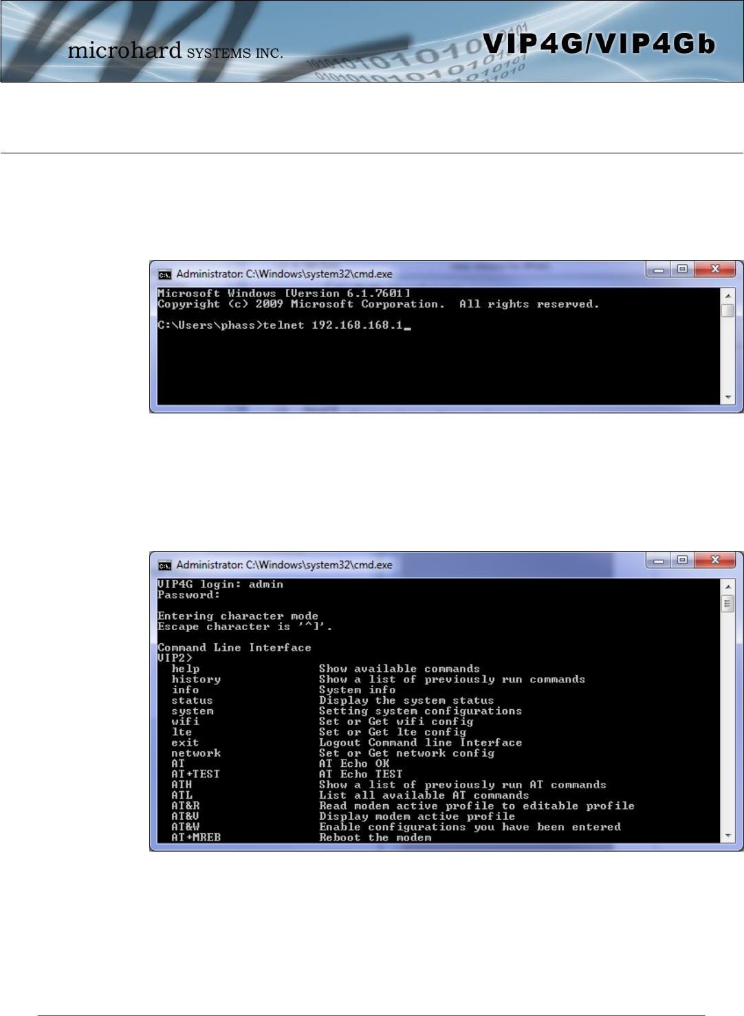
5.1.2 Telnet (TCP/IP)
Telnet can be used to access the AT Command interface of the VIP4G. The default port is TCP Port 23. A
telnet session can be made to the unit using any Telnet application (Windows Telnet, Tera Term,
ProComm etc). Once communication is established, a login is required to continue.
Image 5-3: Establishing a Telnet Session
A session can be made to the WAN IP Address (if allowed in the firewall settings) for remote configuration,
or to the local RJ45 interface (default IP: 192.168.168.1).
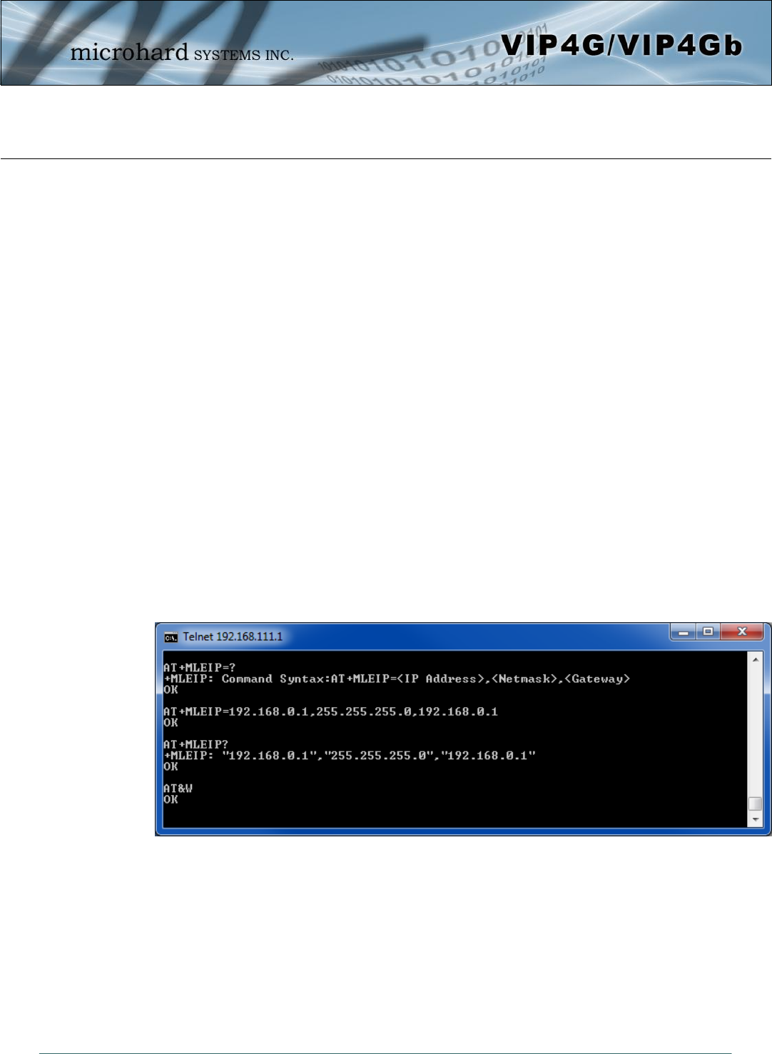
Once a session is established a login is required to continue. As seen in the Serial port setup, the default
login is admin, and the password is admin. Once verified, the AT Command Line Interface menu is shown
and AT Commands can now be issued. (Type “?” or Help to list the commands)
Image 5-4: Telnet AT Command Session
© Microhard Systems Inc. 168
5.0 AT Command Line Interface
5.2 AT Command Syntax
The follow syntax is used when issuing AT Commands on the VIP4G
- All commands start with the AT characters and end with the <Enter> key
- Microhard Specific Commands start with +M
- Help will list top level commands (ATL will list ALL available AT Commands)
- To query syntax of a command: AT+<command_name>=?
- Syntax for commands that are used only to query a setting:
AT<command_name>
- Syntax for commands that can be used to query and set values:
AT<command_name>=parameter1,parameter2,… (Sets Values)
AT<command_name>? (Queries the setting)
Query Syntax:
AT+MLEIP=? <Enter>
+MLEIP: Command Syntax:AT+MLEIP=<IP Address>,<Netmask>,<Gateway>
OK
Setting a value:
AT+MLEIP=192.168.0.1,255.255.255.0,192.168.0.1 <Enter>
OK
Query a setting:
AT+MLEIP? <Enter>
+MLEIP: “192.168.0.1”, “255.255.255.0”, “192.168.0.1”
OK
A screen capture of the above commands entered into a unit is shown below:
Image 5-5: Telnet AT Command Syntax
Once AT commands are entered, the changes are immediate.
ATO or ATA Exits the AT Command Line Interface.

© Microhard Systems Inc. 169
5.0 AT Command Line Interface
5.3 Supported AT Commands
AT
Command Syntax
Echo OK. AT <enter>
Description
Example
ATH
Command Syntax
Show a list of previously run commands. ATH <enter>
Description
Example
Input:
ATH <enter>
Response:
AT Command history: 1. ATH 2. ATL 3. ATH
Input:
AT <enter>
Response:
OK
AT&R
Command Syntax
Read modem profile to editable profile. (Reserved) AT&R <enter>
Description
Example
Input:
AT&R <enter>
Response:
OK
AT+TEST
Command Syntax
Echo TEST AT+TEST <enter>
Description
Example
Input:
AT+TEST <enter>
Response:
AT ECHO TEST:
:0

© Microhard Systems Inc. 170
5.0 AT Command Line Interface
AT&V
Command Syntax
Read modem active profile. AT&V <enter>
Description
Example
Input:
AT&V <enter>
Response:
&V:
hostname:VIP4G
timezone:MST7MDT,M3.2.0,M11.1.0
systemmode:gateway
time mode:sync
OK
AT&W
Command Syntax
Reserved. AT&W <enter>
Description
Example
Input:
AT&W <enter>
Response:
OK
AT+MREB
Command Syntax
Reboots the modem. AT+MREB <enter>
Description
Example
Input:
AT+MREB <enter>
Response:
OK. Rebooting...

© Microhard Systems Inc. 171
5.0 AT Command Line Interface
ATA
Command Syntax
Quit. Exits AT Command session and returns you to
login prompt. ATA <enter>
Description
Example
Input:
ATA <enter>
Response:
OK
IPn3G Login:
ATO
Command Syntax
Quit. Exits AT Command session and returns you to
login prompt. ATO <enter>
Description
Example
Input:
ATA <enter>
Response:
OK
IPn3G Login:
AT+CMGS
Command Syntax
Send SMS message. To send message CTRL+Z
must be entered, to exit, ESC. AT+CMGS=<Phone Number><CR>
text is entered <CTRL+Z/ESC>
Description
Example
Input:
AT+CMGS=4035553776 <enter>
4035553776 Test <ctrl+z>
Response:
OK

© Microhard Systems Inc. 172
5.0 AT Command Line Interface
AT+CMGR
Command Syntax
This command allows the application to read stored
messages. The messages are read from the SIM card
memory.
AT+CMGR=<index>
Description
Example
Input:
AT+CMGR=<index><enter>
Response:
+CMGR: <stat>,<oa>,,<dt>
<data>
OK
Parameters:
<index> Index in SIM card storage of the message
<stat> Status of Message in Memory (Text Mode)
“REC UNREAD” Received unread messages
“REC READ” Received read messages
<oa> Originator Address
String type
<dt> Discharge Time
String format: "yy/MM/dd,hh:mm:ss±zz" (year [00-99]/ month [01-12]/Day [01-31],
Hour:Min:Second and TimeZone [quarters of an hour])
<data> SMS User Data in Text Mode
String type
AT+CMGL
Command Syntax
This command allows the application to read stored
messages by indicating the type of the message to
read. The messages are read from the SIM card
memory.
AT+CMGL=<status>
Status:
0 - Lists all unread messages
1 - Lists all read messages
4 - Lists all messages
Description
Example
Input:
AT+CMGL=1 <enter>
Response:
AT+CMGL=1
+CMGL: 0,"REC READ","+14035553776",,"2013/10/04,11:12:27-06"
Test Message 1
+CMGL: 1,"REC READ","+14035553776",,"2013/10/04,11:12:53-06"
Test Message 2
+CMGL: 2,"REC READ","+14035553776",,"2013/10/04,11:13:06-06"
Another test message!
OK

© Microhard Systems Inc. 173
5.0 AT Command Line Interface
AT+CMGD
Command Syntax
This command handles deletion of a single message
from memory location <index>, or multiple
messages according to <delflag>.
AT+CMGD=<index>,<delflag>
delflag:
0 - Deletes the message specified in <index>
1 - Deletes all read messages
4 - Deletes all messages
Description
Example
Input:
AT+CMGD=0,4 <enter>
Response:
index=0 dflag=4
OK
AT+GMR
Command Syntax
Modem Record Information AT+GMR <enter>
Description
Example
Input:
AT+GMR <enter>
Response:
+GMR:
Hardware Version:v1.0.0 Software Version:v1.1.0 build 1060
Copyright: 2012 Microhard Systems Inc.
System Time: Mon Dec 2 16:03:51 2013
OK
AT+GMI
Command Syntax
Get Manufacturer Identification AT+GMI=<enter>
Description
Example
Input:
AT+GMI<enter>
Response:
+GMI: 2012 Microhard Systems Inc.
OK

© Microhard Systems Inc. 174
5.0 AT Command Line Interface
AT+CNUM
Command Syntax
Check modem’s phone number. AT+CNUM <enter>
Description
Example
Input:
AT+CNUM <enter>
Response:
+CNUM: "+15875558645"
OK
AT+CIMI
Command Syntax
Check modem’s IMEI and IMSI numbers. AT+CIMI <enter>
Description
Example
Input:
AT+CIMI <enter>
Response:
+CIMI: IMEI:012773002108403, IMSI:302720406982933
OK
AT+CCID
Command Syntax
Check modem’s SIM card number. AT+CCID=<enter>
Description
Example
Input:
AT+CCID<enter>
Response:
+CCID: 89302720401025355531
OK

© Microhard Systems Inc. 175
5.0 AT Command Line Interface
AT+MSYSI
Command Syntax
System Summary Information AT+MSYSI <enter>
Description
Example
Input:
AT+MSYSI <enter>
Response:
Carrier:
Carrier:
IMEI:012773002113114
SIMID:89302720401025355531
IMSI:302720406982933
Phone Num: +15878938645
Status: CONNECTED
Network: ROGERS
RSSI:WCDMA RSSI : 70
Temperature:51 degC
Ethernet Port:
MAC:00:0F:92:00:B3:3B
IP:192.168.168.1
MASK:255.255.255.0
Wan MAC:00:0F:92:01:B3:3B
Wan IP:0.0.0.0
Wan MASK:0.0.0.0
System:
Device:VIP4G_MKT
Product:VIP4G_WIFI_N
Image:VIP4G
Hardware:v2.0.0
Software:v1.1.6 build 1184-14
Copyright: 2012 Microhard Systems Inc.
Time: Thu Jun 18 13:25:34 2015
AT+MMNAME
Command Syntax
Modem Name / Radio Description. 30 chars. AT+MMNAME=<modem_name>
Description
Example
Input: (To set value)
AT+MMNAME=VIP4G_CLGY<enter>
Response:
OK
Input: (To retrieve value)
AT+MMNAME=?<enter>
Response:
+MMNAME: VIP4G_CLGY
OK

© Microhard Systems Inc. 176
5.0 AT Command Line Interface
AT+MLEIP
Command Syntax
Set the IP Address, Netmask, and Gateway for the
local Ethernet interface. AT+MLEIP=<IPAddress>, <Netmask>,
<Gateway>
Description
Example
Input:
AT+MLEIP=192.168.168.1,255.255.255.0,192.168.168.1 <enter>
Response:
OK
AT+MDHCP
Command Syntax
Enable/Disable the DHCP server running of the local
Ethernet interface. AT+MDHCP=<action>
0 Disable
1 Enable
Description
Example
Input:
AT+MDHCP=1 <enter>
Response:
OK
AT+MDHCPA
Command Syntax
Define the Starting and Ending IP Address (range)
assignable by DHCP on the local Ethernet interface. AT+MDHCPA=<Start IP>, <End IP>
Description
Example
Input:
AT+MDHCPA=192.168.168.100,192.168.168.200 <enter>
Response:
OK
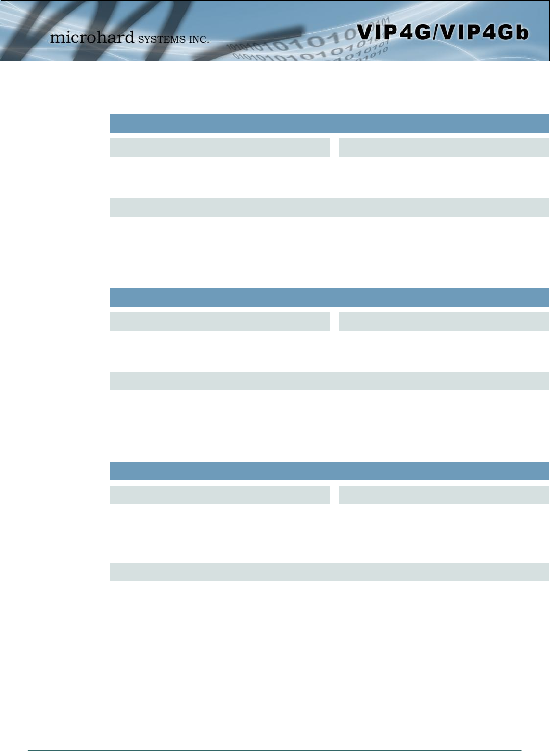
© Microhard Systems Inc. 177
5.0 AT Command Line Interface
AT+MEMAC
Command Syntax
Retrieve the MAC Address of the local Ethernet
interface. AT+MEMAC <enter>
Description
Example
Input:
AT+MEMAC<enter>
Response:
+MEMAC: "00:0F:92:00:40:9A"
OK
AT+MSIP
Command Syntax
Set LAN static IP AT+MSIP=<static IP address> <enter>
Description
Example
Input:
AT+MSIP=192.168.168.1 <enter>
Response:
+MSIP: setting and restarting network...
OK
AT+MSCT
Command Syntax
Set LAN Connection Type. AT+MSCT=<Mode>
Mode:
0 DHCP
1 Static IP
Description
Example
Input:
AT+MSCT=1 <enter>
Response:
OK

© Microhard Systems Inc. 178
5.0 AT Command Line Interface
AT+MNTP
Command Syntax
Enable and define a NTP server. AT+MNTP=<status>,<NTP server>
Status:
0 Disable
1 Enable
Description
Example
Input:
AT+MNTP=1,pool.ntp.org<enter>
Response:
OK
AT+MPIPP
Command Syntax
Enable/Disable IP-Passthrough AT+MPIPP=<Mode>
Mode:
0 Disable
1 Ethernet
Description
Example
Input:
AT+MPIPP=1 <enter>
Response:
OK
AT+MCNTO
Command Syntax
Sets the timeout value for the serial and telnet
consoles. Once expired, user will be return to login
prompt.
AT+MCNTO=<Timeout_s>
0 - Disabled
0 - 65535 (seconds)
Description
Example
Input:
AT+MCNTO=300 <enter>
Response:
OK

© Microhard Systems Inc. 179
5.0 AT Command Line Interface
AT+MTWT
Command Syntax
Enable/Disable the Wireless Traffic Timeout. Unit
will reset if it does not see any traffic from the carrier
for the amount of time defined.
AT+MTWT=<Mode>[,<Interval_s>,<Reboot
Time Limit_s>]
Mode:
0 Disable
1 Enable
Reboot Time Limit:300-60000
Description
Example
Input:
AT+MTWT=1,1,300 <enter>
Response:
OK
AT+MRTF
Command Syntax
Reset the modem to the factory default settings
stored in non-volatile (NV) memory. Unit will reboot
with default settings.
AT+MRTF <action>
Action:
0 pre-set action
1 confirm action
OK
Description
Example
Input:
AT+MRTF=1 <enter>
Response:
OK
AT+MSCMD
Command Syntax
Enable/Disable the Wireless Traffic Timeout. Unit
will reset if it does not see any traffic from the carrier
for the amount of time defined.
AT+MSCMD=<Mode>[,<Filter Mode>[,<Phone
No.1>[,...,<Phone
No.6>]]]
Mode:
0 Disable
1 Enable SMS Command
Filter Mode:
0 Disable
1 Enable Phone Filter
OK
Description
Example
Input:
AT+MSCMD=1,1,403556767,4057890909<enter>
Response:
OK

© Microhard Systems Inc. 180
5.0 AT Command Line Interface
AT+MPWD
Command Syntax
Used to set or change the ADMIN password for the
VIP4G. AT+MPWD=<New password>,<confirm
password>
password: at least 5 characters
Description
Example
Input:
AT+MPWD=admin,admin<enter>
Response:
OK
AT+MDISS
Command Syntax
Configure discovery mode service used by VIP4G
and utilities such as “IP Discovery”. AT+MDISS=<Mode>
Mode:
0 Disable
1 Discoverable
Description
Example
Input:
AT+MDISS=1 <enter>
Response:
OK
AT+MIKACE
Command Syntax
Enable or Disable IMCP ICMP keep-alive check. AT+MIKACE=<Mode>
Mode:
0 Disable
1 Enable
Description
Example
Input:
AT+MIKACE=1<enter>
Response:
OK

© Microhard Systems Inc. 181
5.0 AT Command Line Interface
AT+MIKAC
Command Syntax
Set ICMP Keep-alive check parameters. AT+MIKAC=<host name>, <interval in
seconds>, <count>
Description
Example
Input:
AT+MIKAC=www.google.com,600,10<enter>
Response:
OK
AT+MDDNSE
Command Syntax
Enable/Disable DDNS. AT+MDDNSE=<Mode>
Mode:
0 Disable
1 Enable
Description
Example
Input:
AT+MDDNSE=0<enter>
Response:
OK
AT+MDDNS
Command Syntax
Select DDNS service provider, and login credentials
as required for DDNS services. AT+MDDNS=<service type>,<host>,<user
name>,<password>
service type:
0 changeip
1 dyndns
2 eurodyndns
3 hn
4 noip
5 ods
6 ovh
7 regfish
8 tzo
9 zoneedit
Description
Example
Input:
AT+MDDNS=0,user.dydns.org,user,password <enter>
Response:
OK

© Microhard Systems Inc. 182
5.0 AT Command Line Interface
AT+MEURD1
AT+MEURD2
AT+MEURD3
Command Syntax
Define Event Report UDP Report No.1/2/3. AT+MEURD1=<Mode>[,<Remote IP>,<Remote
Port>,<Interval Ti
me_s>]
Mode:
0 Disable
1 Moden Event Report
2 SDP Event Report
3 Management Report
Description
Example
Input:
AT+MIKAC=www.google.com,600,10<enter>
Response:
OK
AT+MNMSR
Command Syntax
Define NMS Report. AT+MNMSR=<Mode>[,<Remote Port>,<Interval
Time_s>]
Mode:
0 Disable
1 Enable NMS Report
Description
Example
Input:
AT+MNMSR=1,20200,300<enter>
Response:
OK
AT+MGPSR1
AT+MGPSR2
AT+MGPSR3
AT+MGPSR4
Command Syntax
Define GPS Report No.1/2/3/4. AT+MGPSR1=<Mode>[,<Remote IP>,<Remote
Port>,<Interval Ti
me_s>]
Mode:
0 Disable
1 Enable UDP Report
Description
Example
Input:
AT+MGPSR1=1,192.168.168.25,20175,600 <enter>
Response:
OK

© Microhard Systems Inc. 183
5.0 AT Command Line Interface
AT+MCTPS
Command Syntax
Enable/Disable the Comport serial port. This port is
located on the front of the VIP4G and is labelled as
the SERIAL port. It is disabled by default allowing it
to be used for Console/AT Commands. If enabled it
can be used for data.
AT+MCTPS=<Mode>
Mode:
0 Disable
1 Enable
Description
Example
Input:
AT+MCTPS=0<enter>
Response:
OK
AT+MCTBR
Command Syntax
Set Comport baud rate. AT+MCTBR=<Baud Rate>
Baud Rate:
0 300
1 600
2 1200
3 2400
4 3600
5 4800
6 7200
7 9600
8 14400
9 19200
10 28800
11 38400
12 57600
13 115200
Description
Example
Input:
AT+MCTBR=13<enter>
Response:
OK

© Microhard Systems Inc. 184
5.0 AT Command Line Interface
AT+MCTDF
Command Syntax
Set Comport data format AT+MCTDF=<data format>
Data Format:
0 8N1
1 8N2
2 8E1
3 8O1
4 7N1
5 7N2
6 7E1
7 7O1
8 7E2
9 7O2
Description
Example
Input:
AT+MCTDF=0<enter>
Response:
OK
AT+MCTDM
Command Syntax
Set Comport data mode. AT+MCTDM=<Data Mode>
Data Mode:
0 Seamless
1 Transparent
Description
Example
Input:
AT+MCTDM=1<enter>
Response:
OK
AT+MCTCT
Command Syntax
Set Comport character timeout. AT+MCTCT=<timeout_s>
Description
Example
Input:
AT+MCTCT=0<enter>
Response:
OK

© Microhard Systems Inc. 185
5.0 AT Command Line Interface
AT+MCTMPS
Command Syntax
Set comport maximum packet size. AT+MCTMPS=<size>
Description
Example
Input:
AT+MCTMPS=1024<enter>
Response:
OK
AT+MCTP
Command Syntax
Set Comport port priority. AT+MCTP=<Mode>
Mode:
0 Normal
1 Medium
2 High
Description
Example
Input:
AT+MCTP=0<enter>
Response:
OK
AT+MCTNCDI
Command Syntax
Enable/Disable Comport port no-connection data
intake. AT+MCTNCDI=<Mode>
Mode:
0 Disable
1 Enable
Description
Example
Input:
AT+MCTNCDI=1<enter>
Response:
OK

© Microhard Systems Inc. 186
5.0 AT Command Line Interface
AT+MCTMTC
Command Syntax
Set Comport modbus TCP configuration. AT+MCTMTC=<Status>, <Protection status>,
<Protection Key>
Status and Protection Status:
0 Disable
1 Enable
Description
Example
Input:
AT+MCTMTC=0,0,1234<enter>
Response:
OK
AT+MCTIPM
Command Syntax
Set the Comport serial port IP Protocol Mode. AT+MCTIPM=<Mode>
Mode:
0 TCP Client
1 TCP Server
2 TCP Client/Server
3 UDP Point to Point
4 UDP Point to Multipoint(P)
5 UDP Point to Multipoint(MP)
6 UDP Multipoint to Multipoint
7 SMTP Client
9 SMS Transparent Mode
11 GPS Transparent Mode
Description
Example
Input:
AT+MCTIPM=1<enter>
Response:
OK
AT+MCTTC
Command Syntax
Set Comport TCP Client parameters when IP
Protocol Mode is set to TCP Client. AT+MCTTC=<Remote Server IP>, <Remote
Server Port>, <Outgoing timeout_s>
Description
Example
Input:
AT+MCTTC=0.0.0.0,20002,60<enter>
Response:
OK

© Microhard Systems Inc. 187
5.0 AT Command Line Interface
AT+MCTTS
Command Syntax
Set COM2 TCP Server parameters when IP Protocol
Mode is set to TCP Server. AT+MCTTS=<Polling Mode>, <Polling
timeout_s>, <Local Listener Port>,
<Connection timeout_s>
Polling Mode:
0 Monitor
1 Multi-polling
Description
Example
Input:
AT+MCTTS=0,100,20002,300<enter>
Response:
OK
AT+MCTTCS
Command Syntax
Set COM2 TCP Client/Server parameters when IP
Protocol is set to TCP Client/Server mode. AT+MCTTCS=<Remote Server IP>, <Remote
Server Port>, <Outgoing timeout_s>, <Polling
Mode>, <Polling timeout_s>,<Local Listener
Port>, <Connection timeout_s>
Polling Mode:
0 Monitor
1 Multi-polling
Description
Example
Input:
AT+MCTCS=0.0.0.0,20002,60,0,100,20002,300<ent
er>
Response:
OK
AT+MCTUPP
Command Syntax
Set COM2 UDP Point-to-Point parameters when IP
Protocol is set to UDP Point-to-Point mode. AT+MCTUPP=<Remote Server IP>, <Remote
Server Port>, <Liste
ner Port>, <UDP timeout_s>
Description
Example
Input:
AT+MCTUPP=0.0.0.0,20002,20002,10<enter>
Response:
OK

© Microhard Systems Inc. 188
5.0 AT Command Line Interface
AT+MIS
Command Syntax
Module Input Status. AT+MIS
Description
Example
Input:
AT+MIS <enter>
Response:
+MIS: available input status
INPUT 1: 0 open
OK
AT+MOS
Command Syntax
Module Output Status. AT+MOS=<Mode>[,<Setting No.>,<Status>]
Mode:
0 All Output Status
1 Output Setting
Setting No.: 1, 2, 3, 4(if output available)
Status:
0 open
1 close
Description
Example
Input:
AT+MOS=0 <enter>
Response:
+MOS: available output status
OUTPUT 1: 0 open
OK
Input:
AT+MOS=1,1,1 <enter>
Response:
OK

© Microhard Systems Inc. 189
5.0 AT Command Line Interface
ATL <enter>
AT Commands available:
AT AT Echo OK
AT+TEST AT Echo TEST
ATH Show a list of previously run AT commands
ATL List all available AT commands
AT&R Reserved
AT&V Display modem active profile
AT&W Reserved
AT+MREB Reboot the modem
ATA Quit
ATO Quit
AT+CMGS Send SMS
AT+CMGR Read SMS with changing status
AT+CMGL List SMSs with changing status
AT+CMGD Delete SMSs
AT+GMR Modem Record Information
AT+GMI Get Manufacturer Identification
AT+CNUM Check Modem's Phone Number
AT+CIMI Check Modem's IMEI and IMSI
AT+CCID Check Modem's SIM Card Number
AT+MSYSI System summary information
AT+MMNAME Modem Name Setting
AT+MLEIP Set the IP address of the modem LAN Ethernet interface
AT+MDHCP Enable or disable DHCP server running on the Ethernet interface
AT+MDHCPA Set the range of IP addresses to be assigned by the DHCP server
AT+MEMAC Query the MAC address of local Ethernet interface
AT+MSIP Set LAN static IP
AT+MSCT Set LAN Connection Type
AT+MNTP Define NTP server
AT+MPIPP Enable or disable IP-Passthrough
AT+MCNTO Set console timeout
AT+MRTF Reset the modem to the factory default settings from non-volatile (NV) memory
AT+MTWT Enable or disable traffic watchdog timer used to reset the modem
AT+MSCMD Enable or disable system sms command service
AT+MDISS Set discovery service used by the modem
AT+MPWD Set password
AT+MIKACE Enable or disable ICMP keep-alive check
AT+MIKAC Set ICMP keep-alive check
AT+MDDNSE Enable or disable DDNS
AT+MDDNS Set DDNS
AT+MEURD1 Define Event UDP Report No.1
AT+MEURD2 Define Event UDP Report No.2
AT+MEURD3 Define Event UDP Report No.3
AT+MNMSR Define NMS Report
AT+MGPSR1 Define GPS Report No.1
AT+MGPSR2 Define GPS Report No.2
AT+MGPSR3 Define GPS Report No.3
AT+MGPSR4 Define GPS Report No.4
(Continued….)
ATL
Command Syntax
Lists all available AT Commands. ATL <enter>
Description
Example

© Microhard Systems Inc. 190
5.0 AT Command Line Interface
AT+MCTPS Enable or disable com port
AT+MCTBR Set com port baud rate
AT+MCTDF Set com port data format
AT+MCTDM Set com port data mode
AT+MCTCT Set com port character timeout
AT+MCTMPS Set com port maximum packet size
AT+MCTP Set com port priority
AT+MCTNCDI Enable or disable com port no-connection data intake
AT+MCTMTC Set com port modbus tcp configuration
AT+MCTIPM Set com port IP protocol mode
AT+MCTTC Set com port tcp client configuration when IP protocol mode be set to TCP Client
AT+MCTTS Set com port tcp server configuration when IP protocol mode be set to TCP Server
AT+MCTTCS Set com port tcp client/server configuration when IP protocol mode be set to TCP Client/Server
AT+MCTUPP Set com port UDP point to point configuration when IP protocol mode be set to UDP point to point
AT+MIS Module Input status
AT+MOS Module Output status and setting

© Microhard Systems Inc. 191
Appendix A: Serial Interface
DCD Data Carrier Detect - Output from Module - When asserted (TTL low), DCD informs the DTE that a
communications link has been established with another MHX 920A.
RX Receive Data - Output from Module - Signals transferred from the MHX 920A are received by the DTE
via RX.
TX Transmit Data - Input to Module - Signals are transmitted from the DTE via TX to the MHX 920A.
DTR Data Terminal Ready - Input to Module - Asserted (TTL low) by the DTE to inform the module that it is
alive and ready for communications.
SG Signal Ground - Provides a ground reference for all signals transmitted by both DTE and DCE.
DSR Data Set Ready - Output from Module - Asserted (TTL low) by the DCE to inform the DTE that it is alive
and ready for communications. DSR is the module’s equivalent of the DTR signal.
RTS Request to Send - Input to Module - A “handshaking” signal which is asserted by the DTE (TTL low)
when it is ready. When hardware handshaking is used, the RTS signal indicates to the DCE that the host
can receive data.
CTS Clear to Send - Output from Module - A “handshaking” signal which is asserted by the DCE (TTL low)
when it has enabled communications and transmission from the DTE can commence. When hardware
handshaking is used, the CTS signal indicates to the host that the DCE can receive data.
Notes: It is typical to refer to RX and TX from the perspective of the DTE. This should be kept in mind when
looking at signals relative to the module (DCE); the module transmits data on the RX line, and receives
on TX.
“DCE” and “module” are often synonymous since a module is typically a DCE device.
“DTE” is, in most applications, a device such as a host PC.
Module
(DCE)
Signal
Host (e.g. PC)
(DTE)
1 DCD IN
2 RX IN
3 TX OUT
4 DTR OUT
5 SG
6 DSR IN
7 RTS OUT
8 CTS IN
Arrows denote the direction that signals are asserted (e.g., DCD
originates at the DCE, informing the DTE that a carrier is present).
The interface conforms to standard RS-232 signals, so direct connection
to a host PC (for example) is accommodated.
The signals in the asynchronous serial interface are described below:
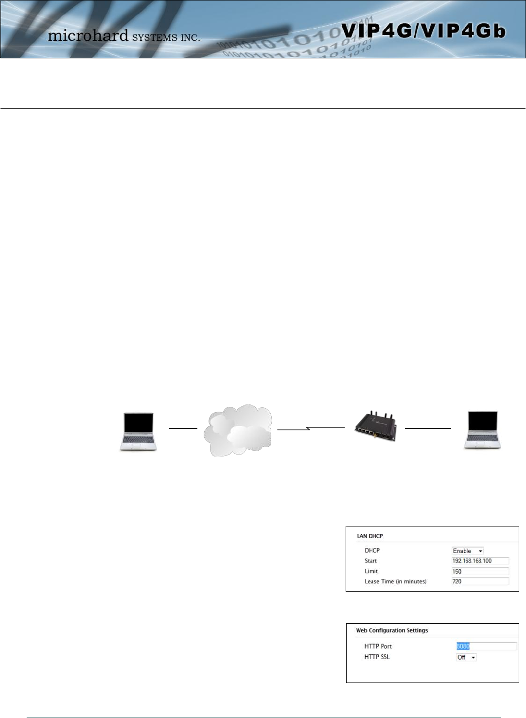
© Microhard Systems Inc. 192
Appendix B: IP-Passthrough Example (Page 1 of 2)
By completing the Quick Start process, a user should have been able to log in and set up the VIP4G to
work with their cellular carrier. By completing this, the modem is ready to be used to access the internet
and provide mobile connectivity. However, a common application of the VIP4G is to access connected
devices remotely. In order to do this, the VIP4G must be told how to deal with incoming traffic, where to
send it to. To accomplish this there are three options :
- IP-Passthrough
- Port Forwarding
- DMZ (a type of Port Forwarding)
In this section we will talk about IP-Passthrough and how to configure the VIP4G and the connected
device/PC to work with IP-Passthrough. IP-Passthrough means that the VIP4G is transparent, and all
outside (WAN) traffic is simply sent directly to a single device connected to one of the physical LAN RJ-45
ports on the VIP4G (With exception of port 80, which is retained for remote configuration (configurable).
Also, any traffic that is sent to the RJ45 port is sent directly out the WAN port and is not processed by the
VIP4G.
IP-Passthrough is ideal for applications where only a single device is connected to the VIP4G, and other
features of the VIP4G are not required. When in passthrough mode, most features of the VIP4G are
bypassed, this includes the serial ports, the GPS features, VPN, the Firewall, and much more. The
advantage of IP-Passthrough is that the configuration is very simple.
In the example below we have a VIP4G connected to a PC (PC2). The application requires that PC1 be
able to access several services on PC2. Using Port Forwarding this would require a new rule created for
each port, and some applications or services may require several ports so this would require several rules,
and the rules may be different for each installation, making future maintenance difficult. For IP-
Passthrough, PC1 only needs to know the Public Static IP Address of the VIP4G, the VIP4G would then
automatically assign, via DHCP, the WAN IP to the attached PC2, creating a transparent connection.
Step 1
Log into the VIP4G (Refer to Quick Start), and ensure that DHCP is
enabled on the Network > LAN page.
Step 2
Since PC2 requires port 80 to be used as its Web server port, port
80 cannot be used on the VIP4G, by default it retains this port for
remote configuration. To change the port used by the VIP4G,
navigate to the System > Settings page as seen below. For this
example we are going to change it to port 8080. When changing
port numbers on the VIP4G, it is recommended to reboot the unit
before continuing, remember the new WebUI port is now 8080 when
you log back into the VIP4G. (e.g. 192.168.168.1:8080).
Cellular Network/
Internet
WAN IP: 74.198.186.193
(Cellular Carrier)
LAN IP: 74.198.186.1 (Used
for WebUI from LAN)
PC2: (DHCP)
WebServer running on port 80
Connected to RJ45
LAN Ethernet Port.
Wireless Cellular
Connection
PC1: Connected to
internet.
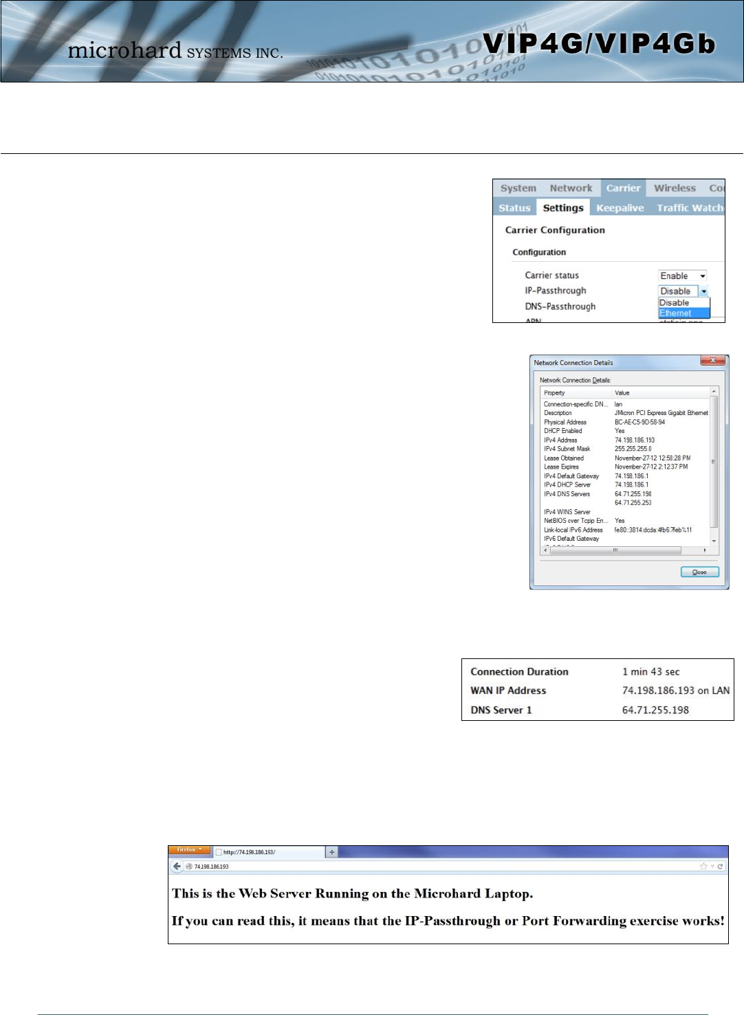
© Microhard Systems Inc. 193
Appendix B: IP-Passthrough Example (Page 2 of 2)
Step 3
Now IP-Passthrough can be enabled on the VIP4G. Under the
Carrier > Settings tab, IP-Passthrough can be found. To enable this
feature, select “Ethernet” from the drop down box. Once the changes
are applied, whichever device is physically connected to the LAN
RJ45 port, will dynamically be assigned the WAN IP Address. In this
example, this would be 74.198.186.193.
The default IP address of 192.168.168.1 on the LAN is no longer
available, but it is still possible to access and configure the VIP4G on
the LAN side, by using the X.X.X.1 IP Address, where the first 3
octets of the WAN IP are used in place of the X’s. (e.g.
74.198.186.1, and remember the HTTP port in this example was
changed to 8080).
Step 4
Attach the remote device or PC to the RJ45 port of the VIP4G. The end
device has to be set up for DHCP to get an IP address from the VIP4G (Or it
needs the carrier IP set as a static IP). In the test/example setup we can
verify this by looking at the current IP address. In the screenshot to the right
we can see that the Laptop connected to the VIP4G has a IP Address of
74.198.186.193, which is the IP address assign by the cellular carrier for the
modem.
Step 5 (Optional)
IP-Passthrough operation can also be verified in the VIP4G. Once IP-
Passthrough is enabled you can access the VIP4G WebUI by one of the
following methods:
Remotely on the WAN side (usually the internet), using the WAN
IP, and the port specified for HTTP operation (or, if enabled, by using the HTTPS (443) ports), in this
example with would be 74.198.186.193:8080.
On the LAN side, by entering in the first 3 octets of the WAN IP and .1 for the fourth, so in our example
74.198.186.1:8080.
Once logged in, navigate to the Carrier > Status page. Under
WAN IP Address it should look something like shown in the
image to the right, 74.198.186.193 on LAN.
Step 6
The last step is to verify the remote device can be accessed. In this example a PC is connected to the RJ45 port of the
VIP4G. On this PC a simple apache web server is running to illustrate a functioning system. On a remote PC, enter the
WAN IP Address of the VIP4G into a web browser. As seen below, when the IP Address of the VIP4G is entered, the
data is passed through to the attached PC. The screen shot below shows that our test setup was successful.
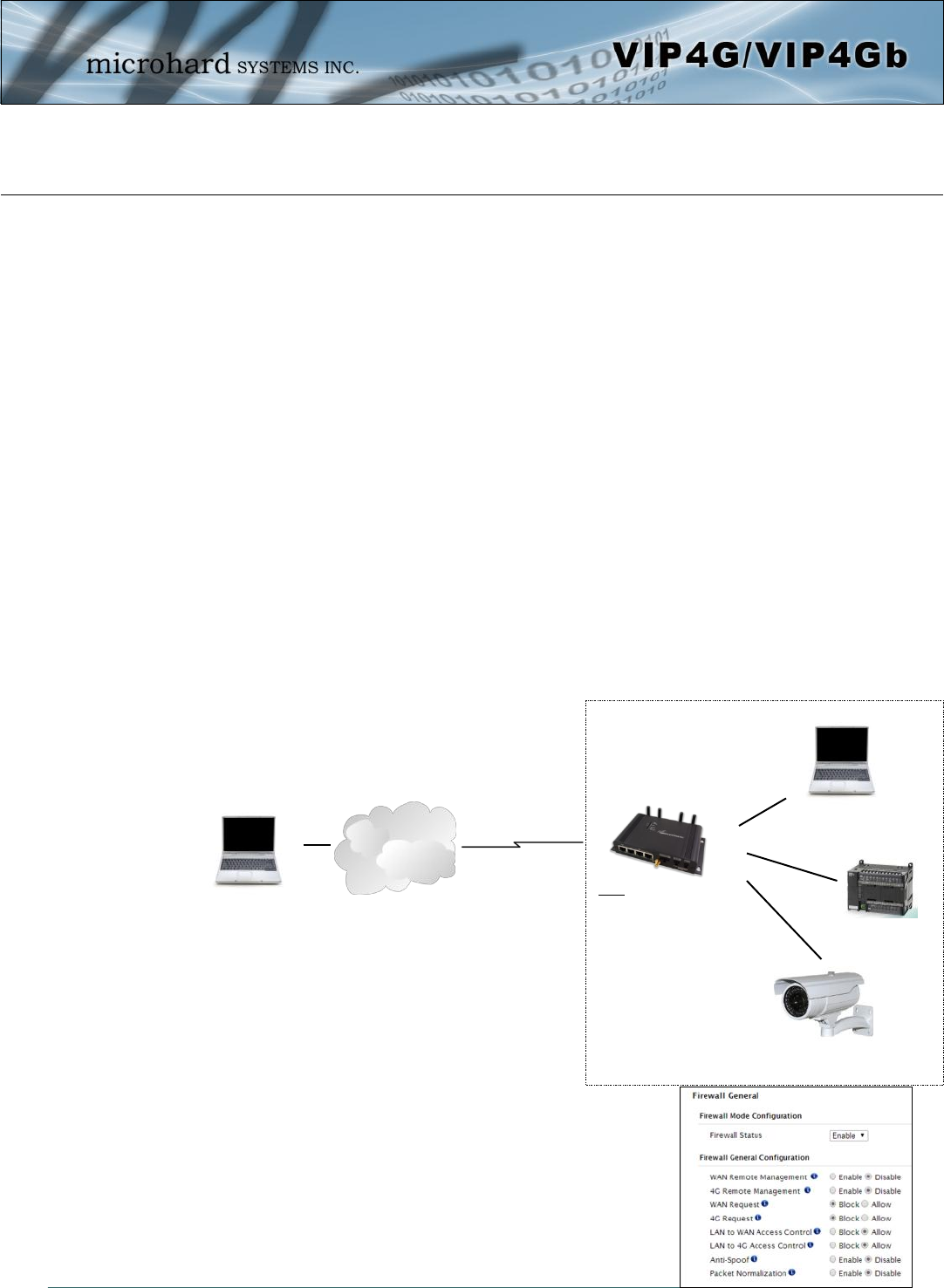
© Microhard Systems Inc. 194
Appendix C: Port Forwarding Example (Page 1 of 2)
By completing the Quick Start process, a user should have been able to log in and set up the VIP4G to
work with their cellular carrier. By completing this, the modem is ready to be used to access the internet
and provide mobile connectivity. However, one of the main applications of the VIP4G is to access
connected devices remotely. In order to do this, the VIP4G must be told how to deal with incoming traffic,
where to send it to. To accomplish this there are three options :
- IP-Passthrough
- Port Forwarding
- DMZ (a type of Port Forwarding)
In the previous section we illustrated how to use and setup IP-Passthrough. In this section we will talk
about port forwarding. Port forwarding is ideal when there are multiple devices connected to the VIP4G, or
if other features of the VIP4G are required (Serial Ports, Firewall, GPS, etc). In port forwarding, the VIP4G
looks at each incoming Ethernet packet on the WAN and by using the destination port number, determines
where it will send the data on the private LAN . The VIP4G does this with each and every incoming packet.
DMZ (a form of port forwarding) is useful for situations where there are multiple devices connected to the
VIP4G, but all incoming traffic is destined for a single device. It is also popular to use DMZ in cases where
a single device is connected but several ports are forwarded and other features of the VIP4G are required,
since in passthrough mode all of these features are lost.
Consider the following example. A user has a remote location that has several devices that need to be
accessed remotely. The User at PC1 can only see the VIP4G directly using the public static IP assigned by
the wireless carrier, but not the devices behind it. In this case the VIP4G is acting a gateway between the
Cellular Network and the Local Area Network of its connected devices. Using port forwarding we can map
the way that data passes through the VIP4G.
Step 1
Log into the VIP4G (Refer to Quick Start), and ensure that the Firewall is
enabled. This can be found under Firewall > General. Also ensure that that
sufficient Rules or IP lists have been setup to allow specific traffic to pass
through the VIP4G. See the Firewall Example in the next Appendix for
information on how to allow connections from an IP or to open ports. Once
that is complete, remember to “Submit” the changes.
Cellular Network/
Internet
VIP4G
WAN IP:
74.198.186.193
(Cellular Carrier)
LAN IP:
192.168.168.1
PC2: 192.168.168.20
Webserver on port 80
Wireless Cellular
Connection
PC1: Connected to
internet.
PLC/RTU: 192.168.168.30
Webserver on port 80
Modbus on port 502
IP Camera: 192.168.168.40
Webserver on Port 80
Wired or Wireless
Devices
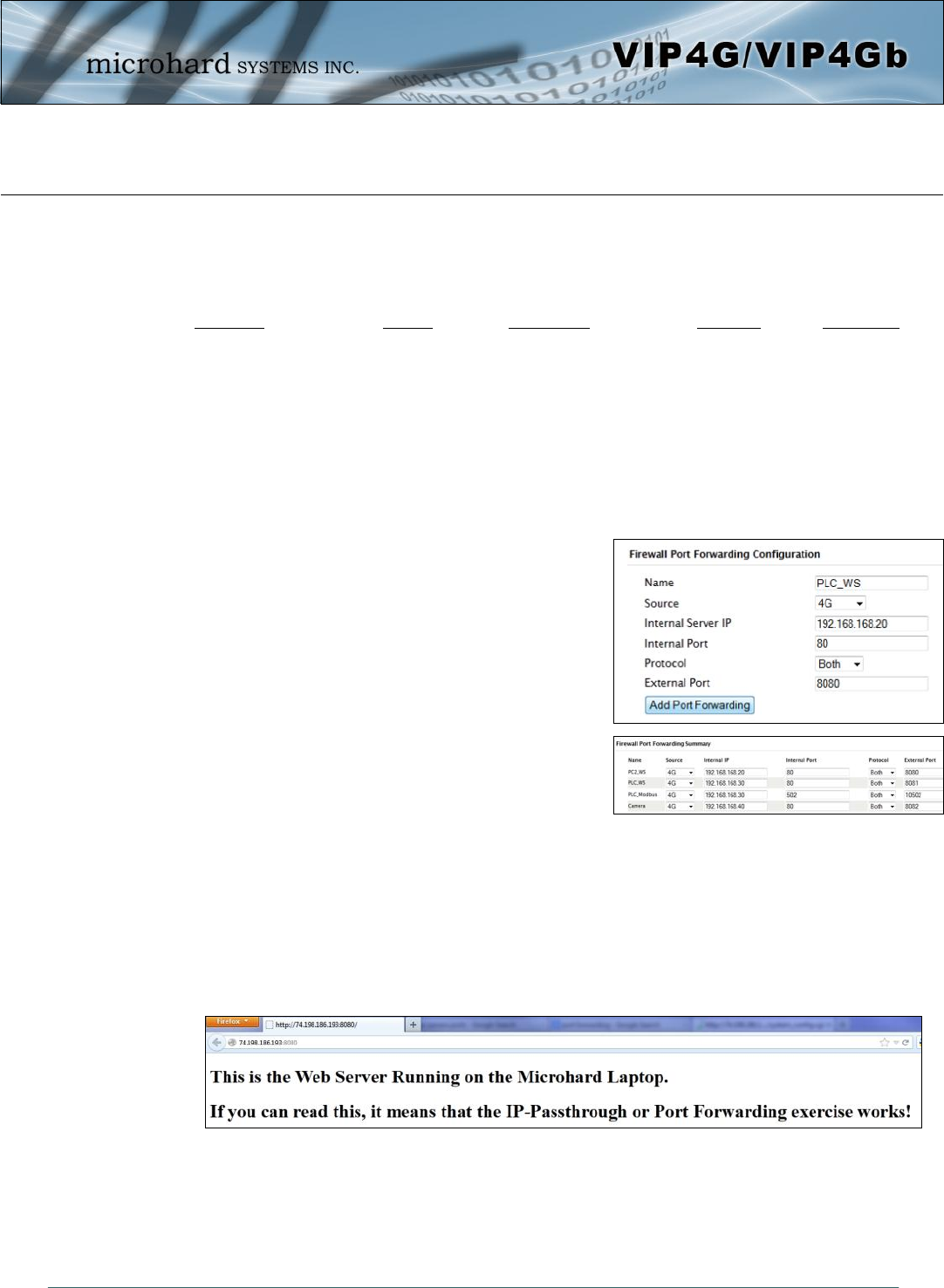
© Microhard Systems Inc. 195
Appendix C: Port Forwarding Example (Page 2 of 2)
Step 2
Determine which external ports (WAN) are mapped to which internal IP Addresses and Ports (LAN). It is important to
understand which port, accessible on the outside, is connected or mapped to which devices on the inside. For this
example we are going to use the following ports, in this case it is purely arbitrary which ports are assigned, some
systems may be configurable, other systems may require specific ports to be used.
Description WAN IP External Port Internal IP Internal Port
VIP4G WebUI 74.198.186.193 80 192.168.168.1 80
PC2 Web Server 74.198.186.193 8080 192.168.168.20 80
PLC Web Server 74.198.186.193 8081 192.168.168.30 80
PLC Modbus 74.198.186.193 10502 192.168.168.30 502
Camera Web Server 74.198.186.193 8082 192.168.168.40 80
Notice that to the outside user, the IP Address for every device is the same, only the port number changes, but on the
LAN, each external port is mapped to an internal device and port number. Also notice that the port number used for the
configuration GUI for all the devices on the LAN is the same, this is fine because they are located on different IP
addresses, and the different external ports mapped by the VIP4G (80, 8080, 8081, 8082), will send the data to the
intended destination.
Step 3
Create a rule for each of the lines above. A rules does not need to
be created for the first line, as that was listed simply to show that
the external port 80 was already used, by default, by the VIP4G
itself. To create port forwarding rules, Navigate to the Firewall >
Port Forwarding menu. When creating rules, each rules requires
a unique name, this is only for reference and can be anything
desired by the user. Click on the “Add Port Forwarding” button
to add each rule to the VIP4G.
Once all rules have been added, the VIP4G configuration should
look something like what is illustrated in the screen shot to the
right. Be sure to “Submit” the Port Forwarding list to the VIP4G.
For best results, reboot the VIP4G.
Step 4
Configure the static addresses on all attached devices. Port forwarding required that all the attached devices have static
IP addresses, this ensure that the port forwarding rules are always correct, as changing IP addresses on the attached
devices would render the configured rules useless and the system will not work.
Step 5
Test the system. The devices connected to the VIP4G should be accessible remotely. To access the devices:
For the Web Server on the PC, use a browser to connect to 74.198.186:193:8080, in this case the same webserver is
running as in the IP-Passthrough example, so the result should be as follows:
To access the other devices/services: For the PLC Web Server: 74.198.186.193:8081, for the Camera
74.198.186.193:8082, and for the Modbus on the PLC telnet to 74.198.186.193:10502 etc.
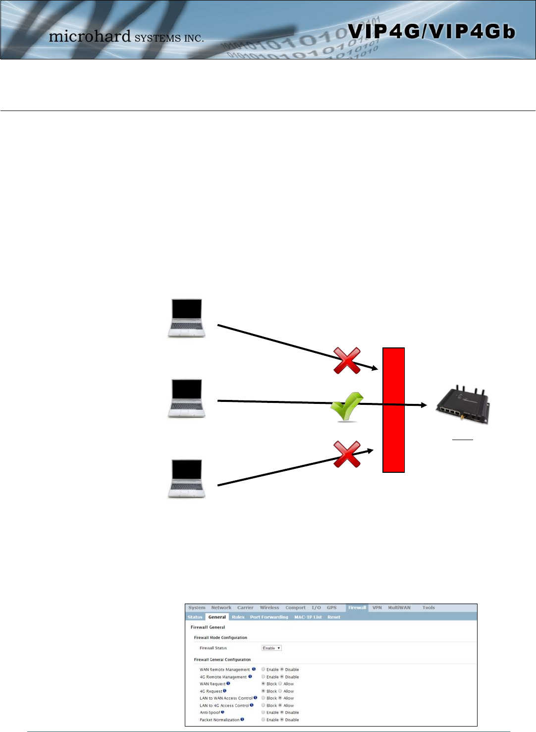
© Microhard Systems Inc. 196
Appendix D: Firewall Example (Page 1 of 2)
By completing the Quick Start process, a user should have been able to log in and set up the VIP4G to
work with their cellular carrier. By completing this, the modem is ready to be used to access the internet
and provide mobile connectivity. However, one of the main applications of the VIP4G is to access
connected devices remotely. Security plays an important role in M2M deployments as in most cases the
modem is publically available on the internet. Limiting access to the VIP4G is paramount for a secure
deployment. The firewall features of the VIP4G allow a user to limit access to the VIP4G and the devices
connected to it by the following means
- Customizable Rules
- MAC and/or IP List
- ACL (Access Control List) or Blacklist using the above tools.
Consider the following example. An VIP4G is deployed at a remote site to collect data from an end device
such as a PLC or RTU connected to the serial DATA port (Port 20001 on the WAN. It is required that only
a specific host (Host A) have access to the deployed VIP4G and attached device, including the remote
management features.
Step 1
Log into the VIP4G (Refer to Quick Start). Navigate to the Firewall > General tab as shown below and ensure that the
Firewall is turned on by enabling the Firewall Status. Next block all WAN traffic by setting the 4G Request to Block,
and disable 4G Remote Management. Be sure to Apply the settings. At this point it should be impossible to access the
VIP4G remotely through its cellular connection.
VIP4G
WAN IP: 173.181.197.156
Local Device on TCP
Port 20001
Host A:
184.71.46.126
Host B:
84.53.23.12
Host C:
186.41.57.101
Firewall
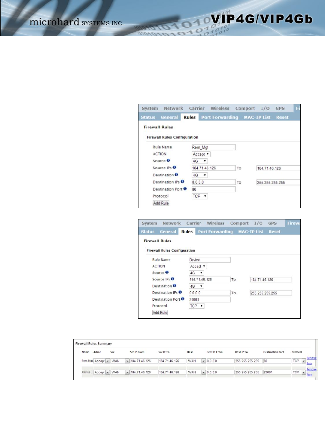
© Microhard Systems Inc. 197
Appendix D: Firewall Example (Page 2 of 2)
Step 2
Under the Rules tab we need to create two new rules. A rule to enable Host A access to the Remote Management Port
(TCP Port 80), and another to access the device attached the to serial port (WAN TCP Port 20001).
After each rule is created be sure to click the ADD Rule button, once both rules are created select the Submit button to
write the rules to the VIP4G. The Firewall Rules Summary should look like what is shown below.
Step 3
Test the connections. The VIP4G should only allow connections to the port specified from the Host A. An alternate
means to limit connections to the VIP4G to a specific IP would have been to use the MAC-IP List Tool. By using Rules,
we can not only limit specific IP’s, but we can also specify ports that can be used by an allowed IP address.
Rule 1
Rule 2
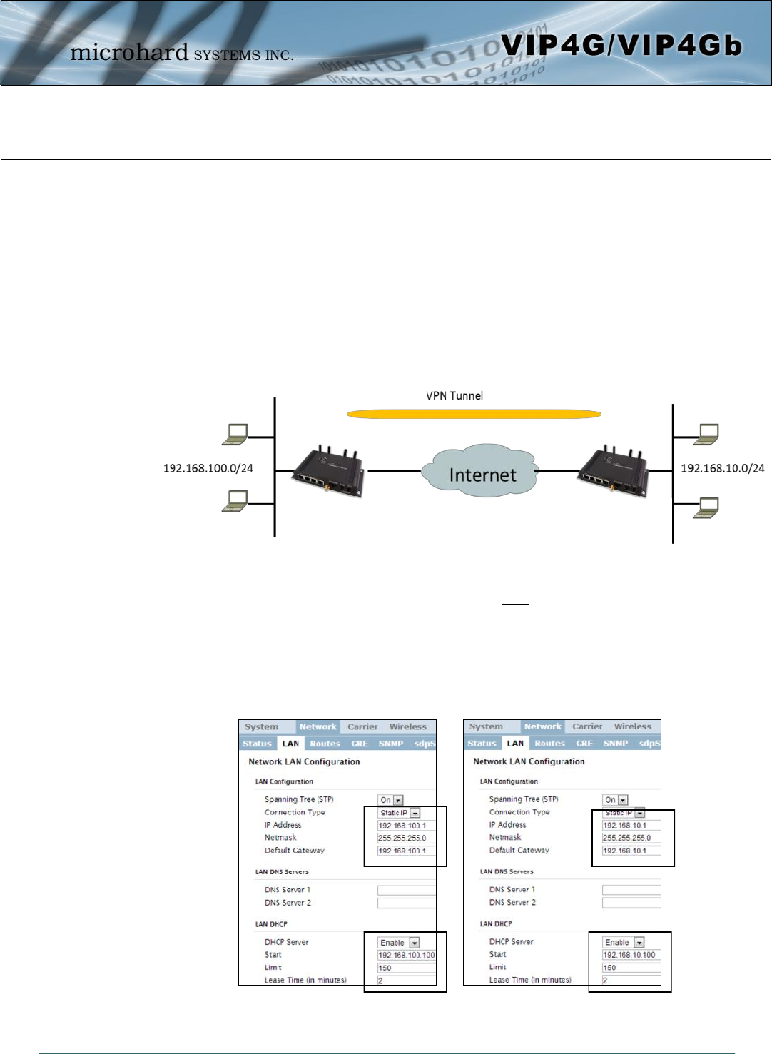
© Microhard Systems Inc. 198
Appendix E: VPN Example (Page 1 of 2)
By completing the Quick Start process, a user should have been able to log in and set up the VIP4G to
work with their cellular carrier. By completing this, the modem is ready to be used to access the internet
and provide mobile connectivity. However, one of the main applications of the VIP4G is to access
connected devices remotely. In addition to Port Forwarding and IP-Passthrough, the VIP4G has several
VPN capabilities, creating a tunnel between two sites, allowing remote devices to be accessed directly.
VPN allows multiple devices to be connected to the VIP4G without the need to individually map ports to
each device. Complete access to remote devices is available when using a VPN tunnel. A VPN tunnel can
be created by using two VIP4G devices, each with a public IP address. At least one of the modems require
a static IP address. VPN tunnels can also be created using the VIP4G to existing VPN capable devices,
such as Cisco or Firebox.
Example: VIP4G to VIP4G (Site-to-Site)
Step 1
Log into each of the VIP4Gs (Refer to Quick Start), and ensure that the Firewall is enabled. This can be found under
Firewall > General. Also ensure that either WAN Request is set to Allow, which allows traffic to come in from the WAN,
or that sufficient Rules or IP lists have been setup to allow specific traffic to pass through the VIP4G. Once that is
complete, remember to “Apply” the changes.
Step 2
Configure the LAN IP and subnet for each VIP4G. The subnets must be different and cannot overlap.
Site A Site B
VIP4G
WAN IP Carrier
Assigned: A.B.C.D
VIP4G
WAN IP Carrier
Assigned: E.F.G.H
Site A Site B
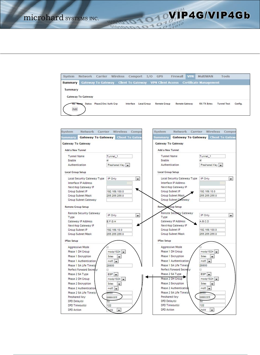
© Microhard Systems Inc. 199
Appendix E: VPN Example (Page 2 of 2)
Step 3
Add a VPN Gateway to Gateway tunnel on each VIP4G.
Step 4
Submit changes to both units. It should be possible to ping and reach devices on either end of the VPN tunnel if both
devices have been configured correctly and have network connectivity.
Site A Site B
A.B.C.D E.F.G.H
Must Match!
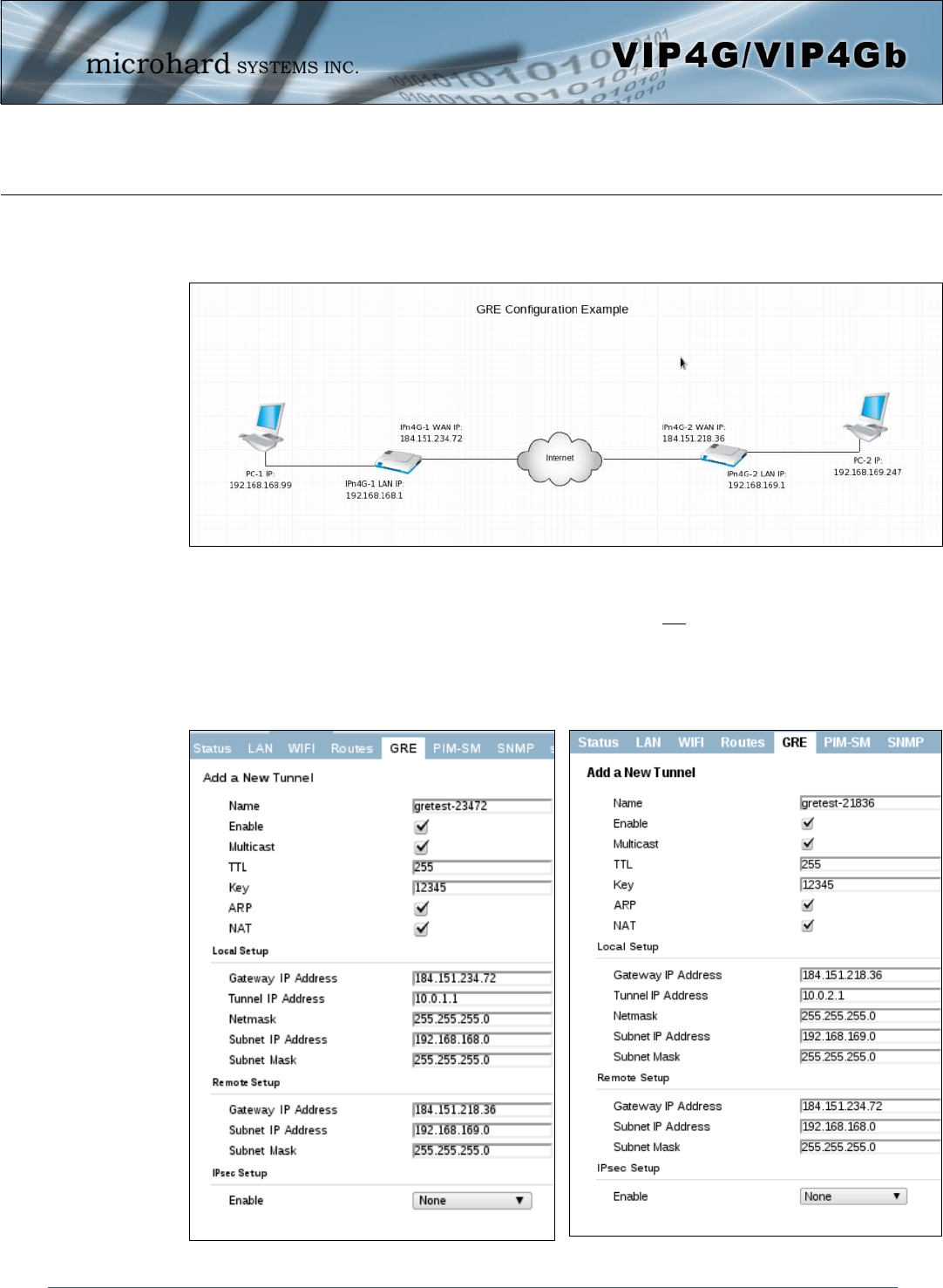
© Microhard Systems Inc. 200
Appendix F: GRE Example
The following pages outline the different GRE configurations available for the VIP4G. This may be useful in
determining which fields are populated by showing a working example. Three different setups are shown:
General GRE (without IPsec), GRE over IPsec (Transport Mode) and GRE over IPsec (Tunnel Mode).
Appendix F Image 1: Network Configuration Example Topology
Prerequisites:
1. Firewall > General > WAN Request Allow (Not Recommened), OR add a specific firewall rules
(Recommened)
2. Add a route on PC-1: ip route add 192.168.169.0/24 via 192.168.168.1 dev eth0
Add a route on PC-2: ip route add 192.168.168.0/24 via 192.168.169.1 dev eth0
Example 1: General GRE (without IPsec)
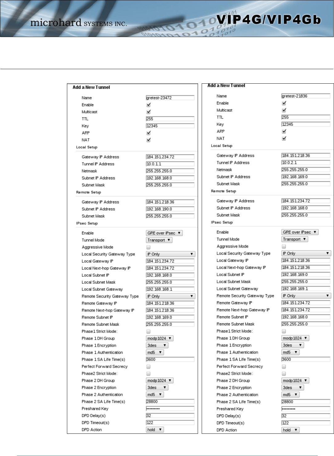
© Microhard Systems Inc. 201
Appendix F: GRE Example
Example 2: GRE over IPsec (Transport Mode)
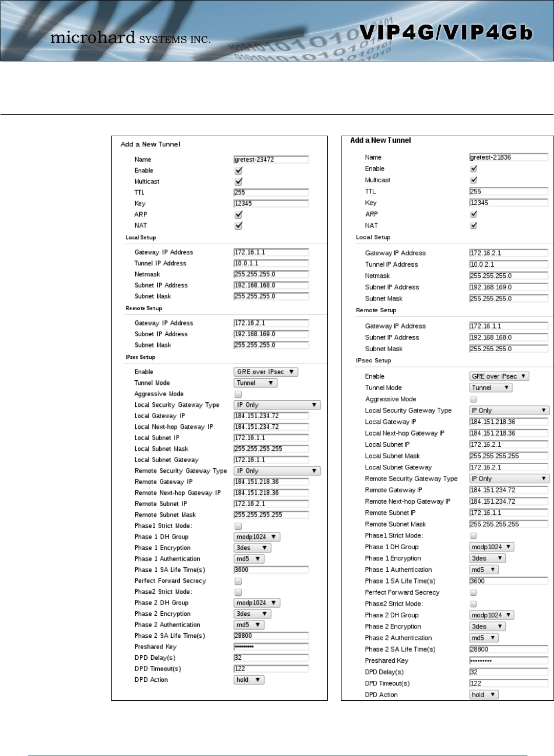
© Microhard Systems Inc. 202
Appendix F: GRE Example
Example 3: GRE over IPsec (Tunnel Mode)

© Microhard Systems Inc. 203
Appendix G: Firmware Recovery Procedure
In event that your unit becomes unresponsive it may be required to perform a firmware recovery procedure
outlined below:
1. Download and save firmware file in a local folder, for example C:\;
2. Separate the PC from the network and set IP to static:
192.168.1.1
255.255.255.0
3. Connect PC Ethernet port to the Ethernet port of the modem to be recovered
4. Start a ping on the PC
C:\>ping 192.168.1.39 -t
Pinging 192.168.1.39 with 32 bytes of data:
Request timed out.
Request timed out.
5. Power cycle modem while pressing and holding CFG(Config) button;
6. Release the CFG button when ping responded:
C:\>ping 192.168.1.39 -t
Pinging 192.168.1.39 with 32 bytes of data:
Request timed out.
Request timed out.
Request timed out.
Reply from 192.168.1.39: bytes=32 time<1ms TTL=128
Reply from 192.168.1.39: bytes=32 time<1ms TTL=128
Reply from 192.168.1.39: bytes=32 time<1ms TTL=128
Reply from 192.168.1.39: bytes=32 time<1ms TTL=128
Note, If ping responds as shown above, then you can probably recover the unit, please proceed.
Otherwise, send the unit back for RMA.
7. Now use TFTP to push firmware file into the corrupted unit:
For example, on Windows XP using following command line:
tftp -i 192.168.1.39 put VIPn4G-v1_1_0-r1084-14.bin (or the file saved).
8. Wait until above command to successfully transfered the image, similar message should show
Transfer successful: xxxxxxx bytes in 5 seconds, nnnnnnn bytes/s, note the number might change for
different firmware file
Note, if you see message above, the unit will re-flash itself and reboot, otherwise call for help or send back
for RMA.
9. Wait for the unit to recover and reboot.

© Microhard Systems Inc. 204
Appendix H: Troubleshooting (FAQ)
Below is a number of the common support questions that are asked about the VIP4G. The purpose of the
section is to provide answers and/or direction on how to solve common problems with the VIP4G.
__________________________________________________________________
Question: Why can’t I connect to the internet/network?
Answer: To connect to the internet a SIM card issued by the Wireless Carrier must be installed and the
APN programmed into the Carrier Configuration of the VIP4G. For instructions of how to log into
the VIP4G refer to the Quick Start.
__________________________________________________________________
Question: What is the default IP Address of the VIP4G?
Answer: The default IP address for the LAN is 192.168.168.1.
__________________________________________________________________
Question: What is the default login for the VIP4G?
Answer: The default username is admin, the default password is admin.
__________________________________________________________________
Question: What information do I need to get from my wireless carrier to set up the VIP4G?
Answer: The APN is required to configure the VIP4G to communicate with a wireless carrier. Some
carriers also require a username and password. The APN, username and password are only
available from your wireless carrier.
Newer units may support an AUTO APN feature, which will attempt to determine the APN from a
preconfigured list of carriers and commonly used APN’s. This is designed to provide quick
network connectivity, but will not work with private APN’s. Success with AUTO APN will vary by
carrier.
________________________________________________________________
Question: How do I reset my modem to factory default settings?
Answer: If you are logged into the VIP4G navigate to the System > Maintenance Tab. If you cannot log in,
power on the VIP4G and wait until the status LED in on solid (not flashing). Press and hold the
CONFIG button until the unit reboots (about 8-10 seconds).
_________________________________________________________________
Question: I can connect the Carrier, but I can’t access the Internet/WAN/network from a connected PC?
Answer: Ensure that you have DHCP enabled or manually set up a valid IP, Subnet, Gateway and DNS
set on the local device.
__________________________________________________________________
Question: I connected a device to the serial port of the VIP4G and nothing happens?
Answer: In addition to the basic serial port settings, the IP Protocol Config has to be configured. Refer to
the Comport Configuration pages for a description of the different options.

© Microhard Systems Inc. 205
Appendix H: Troubleshooting
__________________________________________________________________
Question: How do I access the devices behind the modem remotely?
Answer: To access devices behind the VIP4G remotely, several methods can be used:
A. IP Passthrough - The VIP4G is transparent and the connected device can be access directly.
Refer to The IP-Passthrough Appendix for a detailed example of how this may be deployed.
B. Port Forwarding/DMZ - Individual external WAN ports are mapped to internal LAN IP’s and
Ports. See the Port-Forwarding Appendix for a detailed example.
C. VPN - A tunnel can be created and full access to remote devices can be obtained. Required
the use of multiple modems or VPN routers. See the VPN Appendix on an example of how to set
up a VPN.
_________________________________________________________________
Question: I have set up firewall rules and/or port forwarding rules but they do not work?
Answer: Ensure that the Firewall is Enabled. Even port forwarding requires that the firewall feature is
enabled. If the WAN/4G request is blocked (recommended), additional rules will need to be
created for any external request.
_________________________________________________________________
Question: I have Internet/4G access but I cannot ping the device remotely?
Answer: Ensure that the 4G/WAN request is enabled in the Firewall settings, or create a Firewall rule to
allow ping messages.
_________________________________________________________________
Question: I’m using IP-Passthrough but the serial ports won’t work?
Answer: When using IP-Passthrough, the WAN IP is assigned to the device connected to the Ethernet
port, all traffic is passed through to that device. As a result serials port will not work. The only
port not being passed through is the remote management port (default port 80), which can be
changed in the security settings.
_________________________________________________________________
Question: I’m using IP-Passthrough but the modem won’t take my Firewall settings?
Answer: When using IP-Passthrough, the 4G IP is assigned to the device connected to the Ethernet port,
all traffic is passed through to that device. As a result the firewall settings have no effect on the
unit, and is automatically disabled.
_________________________________________________________________
Question: I cannot get IP-Passthrough to work?
Answer: When using IP-Passthrough, the 4G IP is assigned to the device connected to the Ethernet port,
all traffic is passed through to that device. In order for IP-Passthrough to work, the connected
local device must have DHCP enabled, or the 4G IP set as a static IP in the end device.

© Microhard Systems Inc. 206
Appendix H: Troubleshooting
_________________________________________________________________
Question: Why does my modem reset every 10 minutes (or other time)?
Answer: There are a number of processes in the VIP4G that ensure that the unit is communicating at all
times, and if a problem is detected will reboot the modem to attempt to resolve any issues:
1. Traffic Watchdog - Detects if there is any Wireless Traffic between the VIP4G and the
Cellular Carrier. Will reboot modem when timer expires unless there is traffic. Carrier > Traffic
Watchdog.
2. Keepalive - Attempts to contact a configured host on a defined basis. Will reboot modem if
host is unreachable. Enabled by default to attempt to ping 8.8.8.8. May need to disable on
private networks, or provide a reachable address to check. Access via Carrier > Keepalive.
3. Local Device Monitor - The VIP4G will monitor a local device, if that device is not present the
VIP4G may reboot. Network > LocalMonitor.
_______________________________________________________________
Question: How do I set up VPN?
Answer: Refer to the VPN Appendix for an example.
_________________________________________________________________
Question: Why is the data usage on my modem so high?
Answer: Although it is impossible to answer that question without more detailed information about your
modem, and the devices/application you are using, there are a number of things to keep in mind:
1. Always setup and configure a Firewall on the modem, this is especially important if the modem
is using a publically accessible IP address.
2. Always change the default user/passwords.
3. Turn off any services that are not needed, such as GPS, Comports, SNMP, SSH, anything not
being used specifically in your application.
4. Use the Data Usage alerts to keep informed of daily and monthly data usage of the modem to
avoid surprises once the data bill arrives.

© Microhard Systems Inc. 207
150 Country Hills Landing NW
Calgary, Alberta
Canada T3K 5P3
Phone: (403) 248-0028
Fax: (403) 248-2762
www.microhardcorp.com