Microhard Systems VIP4GABGN20 LTE Ethernet Bridge / Serial Gateway User Manual 1 of 2
Microhard Systems Inc LTE Ethernet Bridge / Serial Gateway 1 of 2
Contents
- 1. User manual
- 2. User Manual 1 of 2
- 3. User Manual 2 of 2
User Manual 1 of 2
VIP4G / VIP4Gb
LTE Ethernet Bridge/Serial Gateway
Document: VIP4Gb Operating Manual.v1.6.1.pdf
FW Version: 1.1.6-r1190-4
Operating Manual
August 2016
150 Country Hills Landing NW
Calgary, Alberta
Canada T3K 5P3
Phone: (403) 248-0028
Fax: (403) 248-2762
www.microhardcorp.com

© Microhard Systems Inc. 2
Important User Information
Warranty
Microhard Systems Inc. warrants that each product will be free of defects in material and workmanship for a
period of one (1) year for its products. The warranty commences on the date the product is shipped by Micro-
hard Systems Inc. Microhard Systems Inc.’s sole liability and responsibility under this warranty is to repair or
replace any product which is returned to it by the Buyer and which Microhard Systems Inc. determines does
not conform to the warranty. Product returned to Microhard Systems Inc. for warranty service will be shipped
to Microhard Systems Inc. at Buyer’s expense and will be returned to Buyer at Microhard Systems Inc.’s ex-
pense. In no event shall Microhard Systems Inc. be responsible under this warranty for any defect which is
caused by negligence, misuse or mistreatment of a product or for any unit which has been altered or modified
in any way. The warranty of replacement shall terminate with the warranty of the product.
Warranty Disclaims
Microhard Systems Inc. makes no warranties of any nature of kind, expressed or implied, with respect to the
hardware, software, and/or products and hereby disclaims any and all such warranties, including but not lim-
ited to warranty of non-infringement, implied warranties of merchantability for a particular purpose, any inter-
ruption or loss of the hardware, software, and/or product, any delay in providing the hardware, software, and/
or product or correcting any defect in the hardware, software, and/or product, or any other warranty. The Pur-
chaser represents and warrants that Microhard Systems Inc. has not made any such warranties to the Pur-
chaser or its agents MICROHARD SYSTEMS INC. EXPRESS WARRANTY TO BUYER CONSTITUTES MICROHARD
SYSTEMS INC. SOLE LIABILITY AND THE BUYER’S SOLE REMEDIES. EXCEPT AS THUS PROVIDED, MICROHARD
SYSTEMS INC. DISCLAIMS ALL WARRANTIES, EXPRESS OR IMPLIED, INCLUDING ANY WARRANTY OF MER-
CHANTABILITY OR FITNESS FOR A PARTICULAR PROMISE.
MICROHARD SYSTEMS INC. PRODUCTS ARE NOT DESIGNED OR INTENDED TO BE USED IN
ANY LIFE SUPPORT RELATED DEVICE OR SYSTEM RELATED FUNCTIONS NOR AS PART OF
ANY OTHER CRITICAL SYSTEM AND ARE GRANTED NO FUNCTIONAL WARRANTY.
Indemnification
The Purchaser shall indemnify Microhard Systems Inc. and its respective directors, officers, employees, suc-
cessors and assigns including any subsidiaries, related corporations, or affiliates, shall be released and dis-
charged from any and all manner of action, causes of action, liability, losses, damages, suits, dues, sums of
money, expenses (including legal fees), general damages, special damages, including without limitation,
claims for personal injuries, death or property damage related to the products sold hereunder, costs and de-
mands of every and any kind and nature whatsoever at law.
IN NO EVENT WILL MICROHARD SYSTEMS INC. BE LIABLE FOR ANY INDIRECT, SPECIAL, CONSEQUENTIAL,
INCIDENTAL, BUSINESS INTERRUPTION, CATASTROPHIC, PUNITIVE OR OTHER DAMAGES WHICH MAY BE
CLAIMED TO ARISE IN CONNECTION WITH THE HARDWARE, REGARDLESS OF THE LEGAL THEORY BEHIND
SUCH CLAIMS, WHETHER IN TORT, CONTRACT OR UNDER ANY APPLICABLE STATUTORY OR REGULATORY
LAWS, RULES, REGULATIONS, EXECUTIVE OR ADMINISTRATIVE ORDERS OR DECLARATIONS OR OTHERWISE,
EVEN IF MICROHARD SYSTEMS INC. HAS BEEN ADVISED OR OTHERWISE HAS KNOWLEDGE OF THE POSSIBIL-
ITY OF SUCH DAMAGES AND TAKES NO ACTION TO PREVENT OR MINIMIZE SUCH DAMAGES. IN THE EVENT
THAT REGARDLESS OF THE WARRANTY DISCLAIMERS AND HOLD HARMLESS PROVISIONS INCLUDED ABOVE
MICROHARD SYSTEMS INC. IS SOMEHOW HELD LIABLE OR RESPONSIBLE FOR ANY DAMAGE OR INJURY, MI-
CROHARD SYSTEMS INC.'S LIABILITY FOR ANYDAMAGES SHALL NOT EXCEED THE PROFIT REALIZED BY MI-
CROHARD SYSTEMS INC. ON THE SALE OR PROVISION OF THE HARDWARE TO THE CUSTOMER.
Proprietary Rights
The Buyer hereby acknowledges that Microhard Systems Inc. has a proprietary interest and intellectual prop-
erty rights in the Hardware, Software and/or Products. The Purchaser shall not (i) remove any copyright, trade
secret, trademark or other evidence of Microhard Systems Inc.’s ownership or proprietary interest or confiden-
tiality other proprietary notices contained on, or in, the Hardware, Software or Products, (ii) reproduce or mod-
ify any Hardware, Software or Products or make any copies thereof, (iii) reverse assemble, reverse engineer or
decompile any Software or copy thereof in whole or in part, (iv) sell, transfer or otherwise make available to
others the Hardware, Software, or Products or documentation thereof or any copy thereof, except in accor-
dance with this Agreement.
© Microhard Systems Inc. 3
Important User Information (continued)
About This Manual
It is assumed that users of the products described herein have either system integration or
design experience, as well as an understanding of the fundamentals of radio communications.
Throughout this manual you will encounter not only illustrations (that further elaborate on the
accompanying text), but also several symbols which you should be attentive to:
Caution or Warning
Usually advises against some action which could result in undesired or
detrimental consequences.
Point to Remember
Highlights a key feature, point, or step which is noteworthy. Keeping
these in mind will simplify or enhance device usage.
Tip
An idea or suggestion to improve efficiency or enhance usefulness.
Information
Information regarding a particular technology or concept.
© Microhard Systems Inc. 4
Important User Information (continued)
Regulatory Requirements
SAMPLE LABEL REQUIREMENT / EXIGENCE D'ÉTIQUETTE :
VIP4G VIP4Gb
FCCID: PKRNVWE371 / NS9VIP4GABGN20
IC: 3229A-E371 / 3143A-VIP4GABGN20
This device complies with Part 15 of the FCC Rules.
Operation is subject to the following two conditions:
(1) this device may not cause harmful interference,
and (2) this device must accept any interference
received including interference that may cause
undesired operation.
FCCID: R17LN930 / NS9VIP4GABGN20
IC: 5131A-LN930 / 3143A-VIP4GABGN20
This device complies with Part 15 of the FCC Rules.
Operation is subject to the following two conditions:
(1) this device may not cause harmful interference,
and (2) this device must accept any interference
received including interference that may cause
undesired operation.
To satisfy FCC RF exposure requirements for mobile transmitting devices, a separation distance of 23cm or more should be maintained
between the antenna of this device and persons during device operation. To ensure compliance, operations at closer than this distance is
not recommended. The antenna being used for this transmitter must not be co-located in conjunction with any other antenna or
transmitter.
WARNING
MAXIMUM EIRP
FCC Regulations allow up to 36dBm Effective Isotropic Radiated Power (EIRP). Therefore, the sum of the transmitted power (in dBm),
the cabling loss and the antenna gain cannot exceed 36dBm.
WARNING
EQUIPMENT LABELING / ÉTIQUETAGE DE L'ÉQUIPEMENT
This device has been modularly approved. The manufacturer, product name, and FCC and Industry Canada identifiers of this product
must appear on the outside label of the end-user equipment.
WARNING
Pour satisfaire aux exigences de la FCC d'exposition RF pour les appareils mobiles de transmission, une distance de séparation de 23cm
ou plus doit être maintenue entre l'antenne de cet appareil et les personnes au cours de fonctionnement du dispositif. Pour assurer le
respect, les opérations de plus près que cette distance n'est pas recommandée. L'antenne utilisée pour ce transmetteur ne doit pas être
co-localisés en conjonction avec toute autre antenne ou transmetteur.
Réglementation de la FCC permettra à 36dBm Puissance isotrope rayonnée équivalente (EIRP). Par conséquent, la somme de la
puissance transmise (en dBm), la perte de câblage et le gain d'antenne ne peut pas dépasser 36dBm.
Ce dispositif a été approuvé de façon modulaire. Le fabricant, le nom du produit, et la FCC et de l'Industrie du Canada identifiants de ce
produit doit figurer sur l'étiquette à l'extérieur de l'équipement de l'utilisateur final.
Please Note: These are only sample labels; different products contain different identifiers. The actual identifiers should be seen on your devices if
applicable. S'il vous plaît noter: Ce sont des exemples d'étiquettes seulement; différents produits contiennent des identifiants différents. Les identifiants
réels devrait être vu sur vos périphériques le cas échéant.
WARNING
TRANSITION UPDATE TO FCC NEW UNII RULES / TRANSITION MISE À JOUR DES REGLES FCC NOUVEAU UNII
The device listed below have been originally approved under FCC rule part 15.247. Based on the implementation of the rule changes from
docket 13-49 this device can no longer be manufactured, sold, imported or placed into operation after June 2, 2016. After this date this device
must comply with the new rule changes provided in docket 13-49. Le dispositif énumérés ci-dessous ont été initialement approuvé en vertu de la
règle FCC part 15.247. Sur la base de la mise en œuvre des changements de règles de dossier 13-49 ce dispositif ne peut plus être fabriqué,
vendu, importée ou mise en service après le 2 Juin 2016. Après cette date, cet appareil doit se conformer aux nouvelles modifications aux règles
prévues dans le dossier 13 -49.
The Memorandum of Opinion and Order issued on March 6 allows for this device to be updated from 15.247 to compliance with new rules
15.407(b)(4)(ii) so long as there are no hardware changes or changes to output power. Device approved under 15.407(b)(4)(ii) may be sold until
March 2, 2020. Le protocole d'Avis et ordonnance rendue le 6 Mars permet à cet appareil à être mis à jour à partir de 15.247 au respect des
nouvelles règles 15.407 (b) (4) (ii) tant qu'il n'y a pas de changement de matériel ou des modifications à la puissance de sortie. Dispositif
approuvé en vertu de 15.407 (b) (4) (ii) peut être vendu jusqu'au 2 Mars, à 2020.
The following device approved under 15.407(b)(4)(ii) may be marketed, sold and imported until March 2, 2020. After this date this device must
comply with the emission limits of 15.407. Le dispositif suivant approuvé en vertu de 15.407 (b) (4) (ii) peuvent être commercialisés, vendus et
importés jusqu'au 2 Mars 2020. Après cette date, ce dispositif doit être conforme aux limites d'émission de 15,407.
VIP4Gb FCC ID: NS9VIP4GABGN20

© Microhard Systems Inc. 5
CSA Class 1 Division 2 Option
CSA Class 1 Division 2 is Available Only on Specifically Marked Units
If marked this for Class 1 Division 2 – then this product is available for use in Class 1, Division 2,
in the indicated Groups on the product.
In such a case the following must be met:
The transceiver is not acceptable as a stand-alone unit for use in hazardous locations. The
transceiver must be mounted within a separate enclosure, which is suitable for the intended
application. Mounting the units within an approved enclosure that is certified for hazardous
locations, or is installed within guidelines in accordance with CSA rules and local electrical and
fire code, will ensure a safe and compliant installation.
Do not connect or disconnect equipment unless power has been switched off or the area is
known to be non-hazardous.
Installation, operation and maintenance of the transceiver should be in accordance with the
transceiver’s installation manual, and the National Electrical Code.
Tampering or replacement with non-factory components may adversely affect the safe use of
the transceiver in hazardous locations, and may void the approval.
The wall adapters supplied with your transceivers are NOT Class 1 Division 2 approved, and
therefore, power must be supplied to the units using the screw-type or locking type connectors
supplied from Microhard Systems Inc. and a Class 1 Division 2 power source within your panel.
If you are unsure as to the specific wiring and installation guidelines for Class 1 Division 2
codes, contact CSA International.

© Microhard Systems Inc. 6
Revision History
Revision Description Initials Date
1.0 Initial Release PEH June 2012
1.1 Updated Screen shots, Firewall settings, added VPN settings PEH August 2012
1.2 Updated Network (LAN/WAN), Added SMS, SMS over Serial, GPS over serial, I/O Rules, Acceler-
ometer, GPS, Updated Firewall, Added MultiWAN, Event Reporting, Modbus, NMS Settings, Up-
dated Screen shots, Updated reference numbers for drawings and images, misc formatting. Added
IP-Passthrough, Port Forwarding Examples. Based on firmware v1.1.6-r1114.
PEH Dec 2012
1.3 Updated to reflect changes made in firmware version v.1.1.6-r1130. Updated Network (LAN/
WAN), Added SMS Alerts, Wireless Virtual Interfaces, AP Isolation, Updated GPS Report, Added
GPSGate, Recorder and Load Record, Updated Gateway-Gateway VPN, Added AT Commands
(Serial & Telnet), Supported AT Commands. Misc formatting & various corrections. Updated
screenshots.
PEH Mar 2013
1.31 Added GPS Receiver specs PEH Mar 2013
1.32 Corrected LTE Frequency Band Specs PEH Apr 2013
1.33 Added PoE information PEH Apr 2013
1.34 Added IP67 Enclosure Dimensional Info PEH Apr 2013
1.4 Updated to reflect changes made up to firmware version v.1.1.6-r1172. Added Data Usage Alerts,
GPS TAIP, WebSocket, Updated Firewall, Updated Network, Updated WAN, Updated MultiWan,
Added Firewall Examples, Updated VPN etc.
PEH Apr 2014
1.5 Updated to firmware version v.1.1.6-r1184-14. PEH June 2015
1.6 Updated to firmware version v1.1.6-r1190-4. Added Router menu. Updated AT Commands, Up-
dated AT commands, Removed Mesh, Updated System, Updated Network, Updated Carrier, Up-
dated Wireless, Updated Tools, Updated Screenshots. Misc Corrections & Formatting.
PEH Dec 2015
1.6.1 Added Transition Update to FCC New UNII Rules PEH Aug 2016

© Microhard Systems Inc. 7
Table of Contents
1.0 Overview ......................................................................................................... 10
1.1 Performance Features ............................................................................................................... 10
1.2 Specifications ............................................................................................................................ 11
2.0 QUICK START ................................................................................................. 13
2.1 Installing the SIM Card ............................................................................................................... 13
2.2 Getting Started with Cellular ....................................................................................................... 13
2.3 Getting Started with WiFi............................................................................................................ 17
2.3.1 Setting up WiFi ................................................................................................................ 17
2.3.1 Connecting to WiFi .......................................................................................................... 18
3.0 Hardware Features ......................................................................................... 20
3.1 VIP4G ....................................................................................................................................... 20
3.1.1 VIP4G Mechanical Drawings ............................................................................................ 21
3.1.2 VIP4G Connections ......................................................................................................... 22
3.1.2.1 Front ................................................................................................................... 22
3.1.2.2 Rear .................................................................................................................... 23
3.1.3 VIP4G Indicators ............................................................................................................. 25
4.0 Configuration.................................................................................................. 26
4.0 Web User Interface ...................................................................................................... 26
4.0.1 Logon Window................................................................................................................. 27
4.1 System ......................................................................................................................... 28
4.1.1 Summary......................................................................................................................... 28
4.1.2 Settings ........................................................................................................................... 29
Host Name ...................................................................................................................... 29
Syslog ............................................................................................................................. 30
Date/Time ....................................................................................................................... 31
HTTP Port Settings .......................................................................................................... 32
HTTPS Port Settings ....................................................................................................... 32
4.1.3 Access Control ................................................................................................................ 33
Password Change ........................................................................................................... 33
Users .............................................................................................................................. 34
4.1.4 Services .......................................................................................................................... 35
RSSI LED’s ..................................................................................................................... 35
SSH ................................................................................................................................ 35
Telnet .............................................................................................................................. 36
4.1.5 Power Saving .................................................................................................................. 37
4.1.6 Maintenance.................................................................................................................... 38
Version Information.......................................................................................................... 38
Firmware Upgrade ........................................................................................................... 38
Reset to Default ............................................................................................................... 39
Backup & Restore Configurations ..................................................................................... 39
4.1.7 Reboot ............................................................................................................................ 40
4.1.8 Logout ............................................................................................................................. 40
4.2 Network ....................................................................................................................... 41
4.2.1 Status ............................................................................................................................. 41
4.2.2 LAN ................................................................................................................................ 42
4.2.3 WAN ............................................................................................................................... 47
4.2.4 WIFI ................................................................................................................................ 49
4.2.5 Switch ............................................................................................................................. 50
4.2.6 Routes ............................................................................................................................ 52
4.2.7 GRE ................................................................................................................................ 54
4.2.8 PIM-SM ........................................................................................................................... 57
4.2.9 SNMP ............................................................................................................................. 61
4.2.10 sdpServer........................................................................................................................ 64
4.2.11 Local Monitor ................................................................................................................... 65

© Microhard Systems Inc. 8
Table of Contents
4.3 Carrier .......................................................................................................................... 66
4.3.1 Status ............................................................................................................................. 66
4.3.2 Settings ........................................................................................................................... 67
IP-Passthrough ................................................................................................................ 68
APN (Access Point Name) ............................................................................................... 69
4.3.3 Keepalive ........................................................................................................................ 71
4.3.4 Traffic Watchdog ............................................................................................................. 72
4.3.5 Dynamic DNS .................................................................................................................. 73
4.3.6 SMS Config ..................................................................................................................... 74
System SMS Commands ................................................................................................. 74
System SMS Alerts .......................................................................................................... 75
4.3.7 SMS ................................................................................................................................ 77
4.3.8 Data Usage Alerts ........................................................................................................... 78
4.4 Wireless ....................................................................................................................... 81
4.4.1 Status ............................................................................................................................. 81
4.4.2 Radio1 ............................................................................................................................ 82
Radio Phy Configuration .................................................................................................. 82
802.11 Mode ................................................................................................................... 82
Channel Frequency ......................................................................................................... 83
Radio Virtual Interface ..................................................................................................... 84
Operating Mode ............................................................................................................... 85
TX Rate........................................................................................................................... 85
TX Power ........................................................................................................................ 86
AP Isolation ..................................................................................................................... 86
SSID ............................................................................................................................... 86
Encryption Type .............................................................................................................. 87
MAC Filter ....................................................................................................................... 87
4.4.3 Hotspot ........................................................................................................................... 88
4.4.4 Netmotion........................................................................................................................ 92
4.4.5 Roam .............................................................................................................................. 93
4.5 Comport ....................................................................................................................... 94
4.5.1 Status ............................................................................................................................. 94
4.5.2 Settings ........................................................................................................................... 95
Data Baud Rate ............................................................................................................... 96
IP Protocol Config ............................................................................................................ 99
TCP Client.................................................................................................................. 99
TCP Server ................................................................................................................ 99
TCP Client/Server....................................................................................................... 100
UDP Point-to-Point ..................................................................................................... 100
SMTP Client ............................................................................................................... 100
SMS Transparent Mode .............................................................................................. 101
GPS Transparent Mode .............................................................................................. 102
4.6 I/O ................................................................................................................................ 103
4.6.1 Status ............................................................................................................................. 103
4.6.2 Output ............................................................................................................................. 104
4.6.3 I/O Rules ......................................................................................................................... 104
4.6.4 Accelerometer ................................................................................................................. 106
4.7 GPS .............................................................................................................................. 108
4.7.1 Location .......................................................................................................................... 108
4.7.2 Settings ........................................................................................................................... 109
4.7.3 GPS Report ..................................................................................................................... 110
4.7.4 GpsGate ......................................................................................................................... 112
4.7.5 Recorder ......................................................................................................................... 115
4.7.6 Load Record.................................................................................................................... 117
4.7.7 TAIP................................................................................................................................ 119

© Microhard Systems Inc. 9
Table of Contents
4.8 Firewall ....................................................................................................................... 121
4.8.1 Status ............................................................................................................................. 121
4.8.2 General ........................................................................................................................... 122
4.8.3 Rules .............................................................................................................................. 124
4.8.4 Port Forwarding ............................................................................................................... 126
DMZ ................................................................................................................................ 126
4.8.5 MAC-IP List ..................................................................................................................... 128
MAC List Configuration .................................................................................................... 128
IP List Configuration ........................................................................................................ 129
4.8.6 Reset Firewall to Defaults ................................................................................................ 130
4.9 Router .......................................................................................................................... 131
4.9.1 RIPV2 ............................................................................................................................. 131
4.9.2 OSPF .............................................................................................................................. 132
4.10 VPN ............................................................................................................................ 132
4.10.1 Summary......................................................................................................................... 132
4.10.2 Gateway to Gateway ....................................................................................................... 134
4.10.3 Client to Gateway (L2TP Client) ....................................................................................... 139
4.10.4 VPN Client Access .......................................................................................................... 141
4.10.5 Certificate Management ................................................................................................... 142
4.11 MultiWAN ..................................................................................................................... 143
4.11.1 Status ............................................................................................................................. 143
4.11.2 Settings ........................................................................................................................... 144
4.12 Tools ............................................................................................................................ 146
4.12.1 Discovery ...................................................................................................................... 146
4.12.2 Netflow Reports ............................................................................................................. 147
4.12.3 NMS Settings................................................................................................................. 149
4.12.4 Event Report ................................................................................................................. 153
4.12.4.1 Configuration ................................................................................................... 153
4.12.4.2 Message Structure ........................................................................................... 154
4.12.4.3 Message Payload ............................................................................................. 155
4.12.5 Modbus ......................................................................................................................... 156
4.12.5.1 TCP Modbus .................................................................................................... 156
4.12.5.2 COM (Serial) Modbus ....................................................................................... 158
4.12.5.3 Modbus Data Map ............................................................................................ 159
4.12.6 Websocket..................................................................................................................... 160
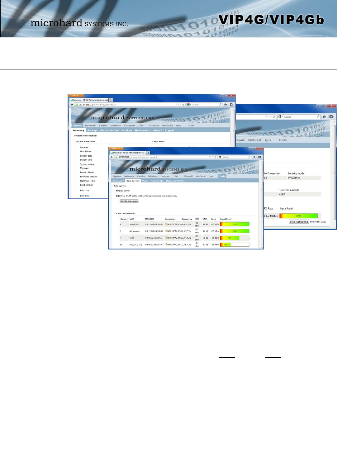
4.12.7 Site Survey .................................................................................................................... 162
4.12.8 Ping............................................................................................................................... 163
4.12.9 TraceRoute.................................................................................................................... 164
4.12.10 Traffic ........................................................................................................................... 165
5.0 AT Command Line Interface .......................................................................... 166
5.1 AT Command Overview .............................................................................................. 166
5.1.1 Serial Port ..................................................................................................................... 166
5.1.2 Telnet (TCP/IP) .............................................................................................................. 167
5.2 AT Command Syntax .................................................................................................. 168
5.3 Supported AT Commands .......................................................................................... 169
Appendices .......................................................................................................... 191
Appendix A: Serial Interface................................................................................................................ 191
Appendix B: IP-Passthrough Example ................................................................................................. 192
Appendix C: Port Forwarding Example ................................................................................................ 194
Appendix D: Firewall Example ............................................................................................................ 196
Appendix E: VPN Example ................................................................................................................ 198
Appendix F: GRE Example ................................................................................................................. 200
Appendix G: Firmware Recovery Procedure ........................................................................................ 203
Appendix H: Troubleshooting (FAQ) .................................................................................................... 204

© Microhard Systems Inc. 10
1.0 Overview
The VIP4G is a high-performance 4G LTE Cellular Ethernet & Serial Gateway with 802.11 a/
b/g/n WiFi capability, 4 Gigabit Ethernet Ports, 4x Digital I/O, and a fully complimented
RS232/485/422 serial port.
The VIP4G utilizes the cellular infrastructure to provide network access to wired and wireless
devices anywhere cellular coverage is supported by a cellular carrier. The VIP4G supports up
to 100Mbps when connected to a LTE enabled carrier, or global fallback to 3G/Edge networks
for areas without 4G LTE.
Providing reliable wireless Ethernet bridge functionality as well gateway service for most
equipment types which employ an RS232, RS422, or RS485 interface, the VIP4G can be
used in a limitless number and types of applications such as:
1.1 Performance Features
Key performance features of the VIP4G include:
High-speed backbone
IP video surveillance
Voice over IP (VoIP)
Ethernet wireless
extension
WiFi Hotspot
Legacy network/device
migration
SCADA (PLC’s, Modbus,
Hart)
Facilitating internetwork
wireless communications
Fast 4G LTE Link to Wireless Carrier
Up to 100Mbps Downlink / 50 Mbps Uplink
Fast Data Rates to 802.11a/b/g/n WiFi Devices
Digital I/O - 4 Inputs, 4 Outputs
DMZ and Port Forwarding
4 - 10/100/1000 Ethernet Ports (WAN/LAN)
Integrated GPS (TCP Server/UDP Reporting)
User interface via local console, telnet, web browser
communicates with virtually all PLCs, RTUs, and serial devices through either
RS232, RS422, or RS485 interface
Local & remote wireless firmware upgradable
User configurable Firewall with IP/MAC ACL
IP/Sec secure VPN and GRE Tunneling

© Microhard Systems Inc. 11
VIP4G VIP4Gb
4G LTE B4/B17 (1700/2100/700 MHz)
Global Fallback to:
HSPA+/UMTS 850/AWS/1900/2100 MHz
GPRS 850/900/1800/1900 MHz
LTE FDD (Bands 1-5,7,8,13,17,18,19,20)
UMTS | DC-HSPA+ (Bands 1,2,4,5,8)
GSM | GPRS | EDGE (Bands 2,3,5,8)
3GPP Protocol Stack Release 9
4G LTE
Up to 100 Mbps downlink
Up to 50 Mbps uplink
LTE: DL 100 Mbps, UL 50 Mbps
HSPA+: DL 21 Mbps, UL 5.7 Mbps
WCDMA: DL/UL 384 kbps
EDGE Class 33: DL/UL 236.8 kbps
GPRS Class 33: DL/UL 85.6kbps
1.0 Overview
1.2 Specifications
For detailed specifications, please see the specification sheets available on the Microhard web-
site @ http:///www.microhardcorp.com for your specific model.
Electrical/General
Cellular:
Supported Bands:
Data Features:
SIM Card: 1.8 / 3.0 V
WiFi: (Order Options)
Frequency: 2.4 GHz / 5.8 GHz
Spread Method: OFDM/QPSK/16QAM/64QAM
Data Rates: 802.11 b/g (up to 30dBm) or 802.11 a/b/g/n (up to 20 dBm)
TX Power: Adjustable (See above)
Data Encryption: WEP, WPA(PSK), WPA2(PSK), WPA+WPA2 (PSK)
(Subject to Export Restrictions)
General:
Input Voltage: 7 - 30 VDC
Power over Ethernet: 802.3af Passive PoE on Ethernet Port
Serial Baud Rate: 300bps to 921kbps
Ethernet: 10/100/1000 BaseT, Auto - MDI/X, IEEE 802.3
Network Protocols: TCP, UDP, TCP/IP, TFTP, ARP, ICMP, DHCP, HTTP,
HTTPS*, SSH*, SNMP, FTP, DNS, Serial over IP
Operating Modes: Access Point, Client/Station, Repeater

© Microhard Systems Inc. 12
1.0 Overview
1.2 Specifications (Continued)
Management: Local Serial Console, Telnet, WebUI, SNMP, FTP &
Wireless Upgrade
Diagnostics: Status LED’s, RSSI, Ec/No, Temperature, Remote Diagnostics,
Watchdog, UDP Reporting
Digital I/O: 4 Inputs / 4 Outputs
GPS:
Navigation Update Rate: Up to 5 Hz
Accuracy: Position: 2.5 m CEP
SBAS: 2.0 m CEP
Acquisition: Cold Starts: 27 seconds
Aided Starts: 4 seconds
Hot Starts: 1 second
Sensitivity: Tracking: -159 dBm
Cold Starts: -147 dBm
Hot Starts: -156 dBm
Environmental
Operation Temperature: -40oF(-40oC) to 185oF(85oC)
Humidity: 5% to 95% non-condensing
Mechanical
Dimensions: 5.65” (145mm) X 3.72” (95mm) X 1.20” (30mm)
Weight: Approx. 405 grams
Connectors:
Antenna: Wi-Fi: 2x RP-SMA Female
Cellular: 2x SMA Female (Main, DIV)
GPS: 1x SMA Female (Supports Active & Passive Antennas with LNA)
Data: RS232 Data: DE-9 Female
RS485: SMT: 6-Pin Micro MATE-N-LOK AMP 3-794618-6
Mating Connector: 6-Pin Micro MATE-N-LOK AMP 794617-6
Ethernet : 4x RJ-45
PWR, Misc: Power: SMT: 4-Pin Micro MATE-N-LOK AMP 3-794618-4
Mating Connector: 4-Pin Micro MATE-N-LOK AMP 794617-4
Misc: Digital I/O: SMT: 10-Pin Micro MATE-N-LOK AMP 4-794618-0
Mating Connector: 10-Pin Micro MATE-N-LOK AMP 1-794617-0
IP67 Enclosure (Optional):
Dimensions: Approx: 8.4”(213mm) X 7.2”(182mm) X 1.75” (44mm)
Weight: Approx: 1.25 kg
© Microhard Systems Inc. 13
2.0 Quick Start
This QUICK START guide will walk you through the setup and process required to access the
WebUI configuration window and to establish a basic wireless connection to your carrier.
Note that the units arrive from the factory with the Local Network setting configured as
‘Static’ (IP Address 192.168.168.1, Subnet Mask 255.255.255.0, and Gateway
192.168.168.1), in DHCP server mode. (This is for the LAN Ethernet Adapter on the back of
the VIP4G unit.
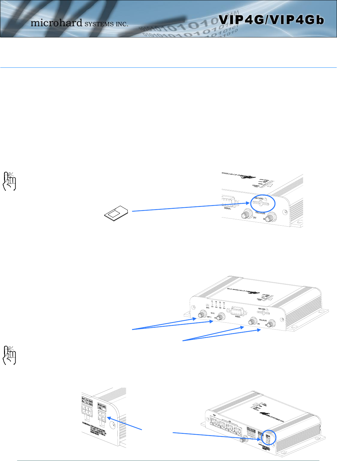
2.1 Installing the SIM Card
Before the VIP4G can be used on a cellular network a valid SIM Card for your Wireless
Carrier must be installed. Insert the SIM Card into the slot as shown below.
2.2 Getting Started with Cellular
Connect the Antenna’s to the applicable ANTENNA jack’s of the VIP4G.
Connect the power connector to the power adapter and apply power to the unit, once the
blue CPU LED is on solid, proceed to the next step.
SIM Card Slot
To reset to factory
defaults, press and hold
the CFG button for 8
seconds with the VIP4G
powered up. The LED’s
will flash quickly and the
IP4G will reboot with
factory defaults.
Use the MHS-supplied
power adapter or an
equivalent power source.
WiFi Antenna’s
Cellular
Antenna’s
9-30VDC
© Microhard Systems Inc. 14
2.0 Quick Start
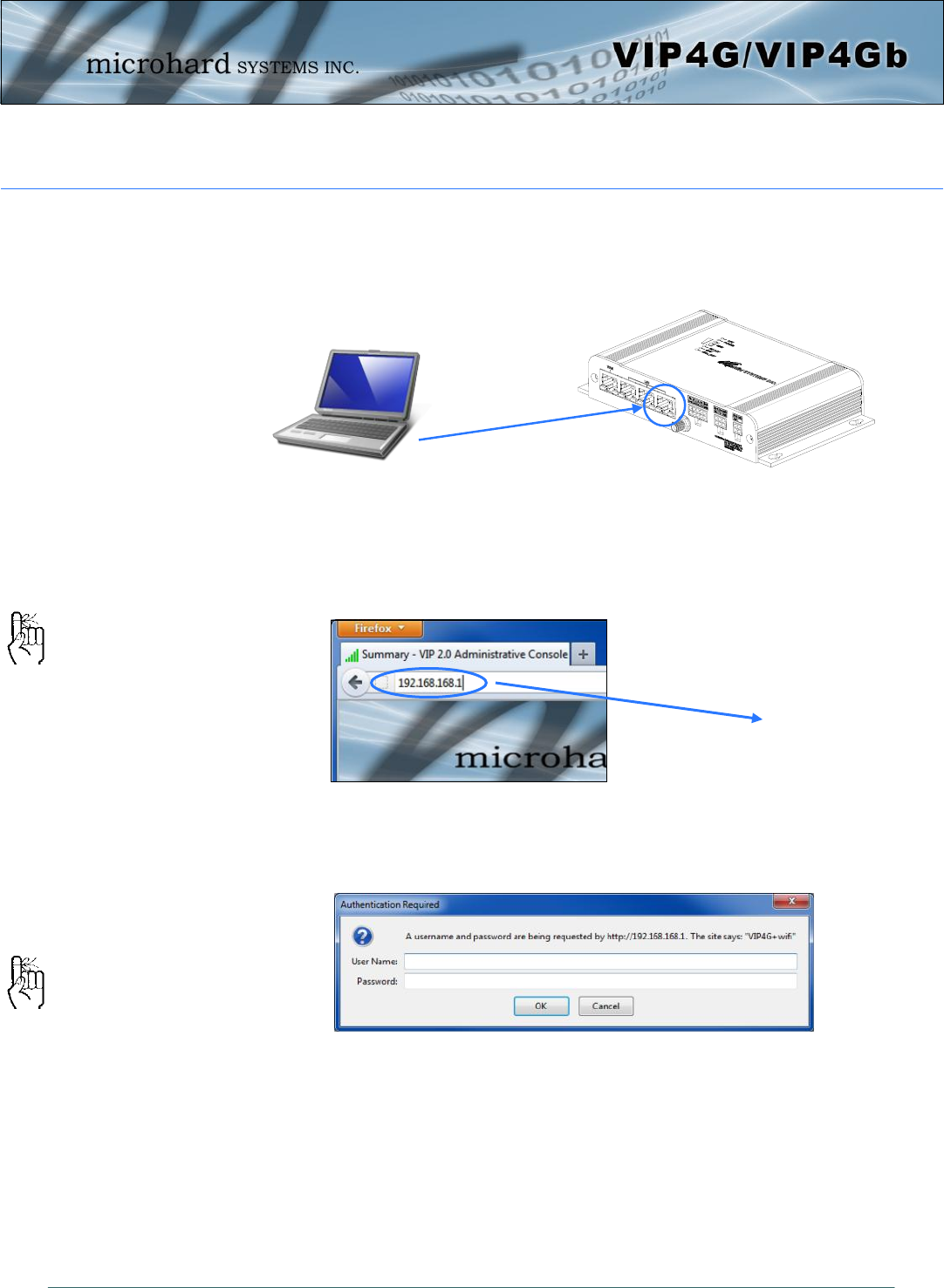
Connect A PC configured for DHCP directly to one of the LAN ETHERNET ports of the
VIP4G, using an Ethernet Cable. If the PC is configured for DHCP it will acquire a IP Ad-
dress from the VIP4G.
Open a Browser Window and enter the IP address 192.168.168.1 into the address bar.
The VIP4G will then ask for a Username and Password. Enter the factory defaults listed
below.
192.168.168.1
The factory default network
settings:
IP: 192.168.168.1
Subnet: 255.255.255.0
Gateway: 192.168.168.1
The Factory default login:
User name: admin
Password: admin
The factory default login:
User name: admin
Subnet: admin
It is always a good idea to
change the default admin
login for future security.
© Microhard Systems Inc. 15
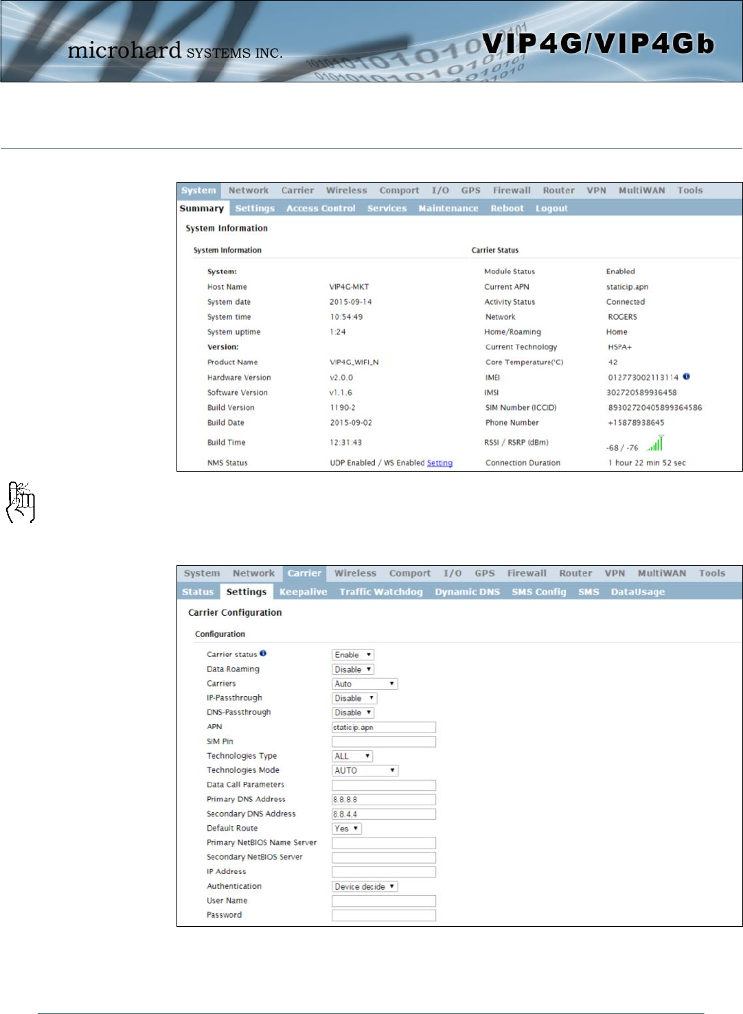
Once successfully logged in, the System Summary page will be displayed.
As seen above under Carrier Status, the SIM card is installed, but an APN has not been
specified. Setting the APN to auto (default) may provide quick network connectivity, but
may not work with some carriers, or with private APN’s. To set or change the APN, click
on the Carrier > Settings tab and enter the APN supplied by your carrier in the APN field.
Some carriers may also require a Username and Password.
Once the APN and any other required information is entered to connect to your carrier,
click on “Submit”. Return to the System > Summary tab.
2.0 Quick Start
Auto APN: Introduced in
firmware version v1.1.6-
r1142, the VIP4G will attempt
to detect the carrier based on
the SIM card installed and
cycle through a list of
commonly used APN’s to
provide quick network
connectivity.
© Microhard Systems Inc. 16
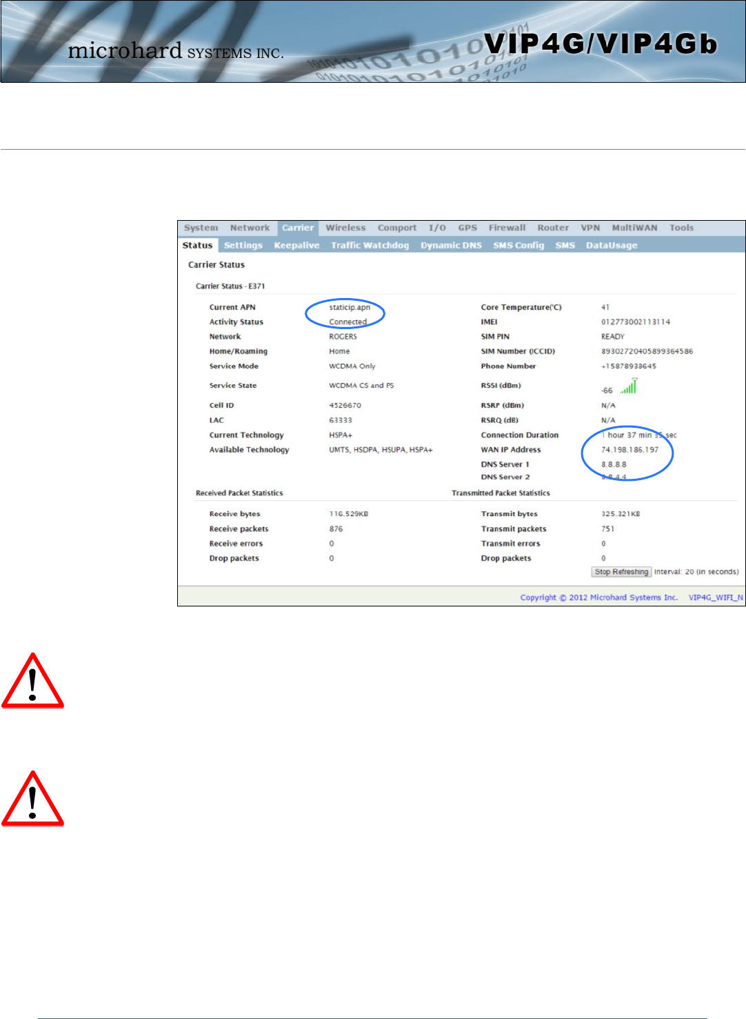
On the Carrier > Status Tab, verify that a WAN IP Address has been assigned by your
carrier. It may take a few minutes, so try refreshing the page if the WAN IP Address
doesn’t show up right away. The Activity Status should also show “Connected”.
If you have set a static IP on your PC, you may need to add the DNS Servers shown in
the Carrier Status Menu to you PC to enable internet access.
Congratulations! Your VIP4G is successfully connected to your Cellular Carrier. The next
section gives a overview on enabling and setting up the WiFi Wireless features of the mo-
dem giving 802.11 devices network access.
To access devices connected to VIP4G remotely, one or more of the following must be
configured: IP-Passthrough, Port Forwarding, DMZ. Another option would be to set up a
VPN.
Ensure that all default passwords are changed to limit access to the mo-
dem. The admin password can be changed at the System > Access Con-
trol menu.
For best practices and to limit data charges it is critical to properly set
up the firewall. (Especially important for Public Static IP addresses.)
2.0 Quick Start
Ensure the default
passwords are changed.
Set up appropriate firewall
rules to block unwanted
incoming data.
© Microhard Systems Inc. 17
2.3 Getting Started with WiFi
This Quick Start section walks users through setting up a basic WiFi AP (Access Point). For
additional settings and configuration considerations, refer to the appropriate sections in the
manual. This walkthrough assumes all setting are in the factory default state.
2.3.1 Setting up WiFi
Use Section 2.2 Getting Started with Cellular to connect, power up and log in and con-
figure the Carrier in a VIP4G.
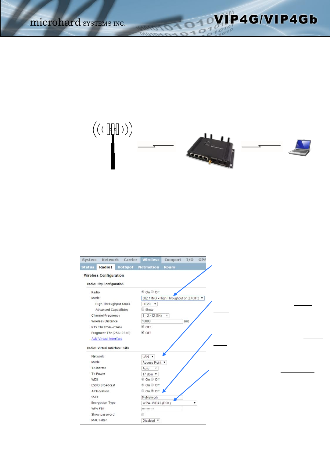
Click on the Wireless > Radio1 Tab to setup the WiFi portion of the VIP4G.
Cell Tower
2.0 Quick Start
4G LTE 802.11g/n
In Radio1 Phy Configuration, ensure
the mode is set for 802.11NG.
In the Radio1 Virtual Interface, en-
sure that the Mode is set for Access
Point.
Enter a name for the Wireless Network
under SSID. This example uses MyNet-
work
(Recommended) Set a password for the
WiFi, this example uses MyPassword
Click Submit.
© Microhard Systems Inc. 18
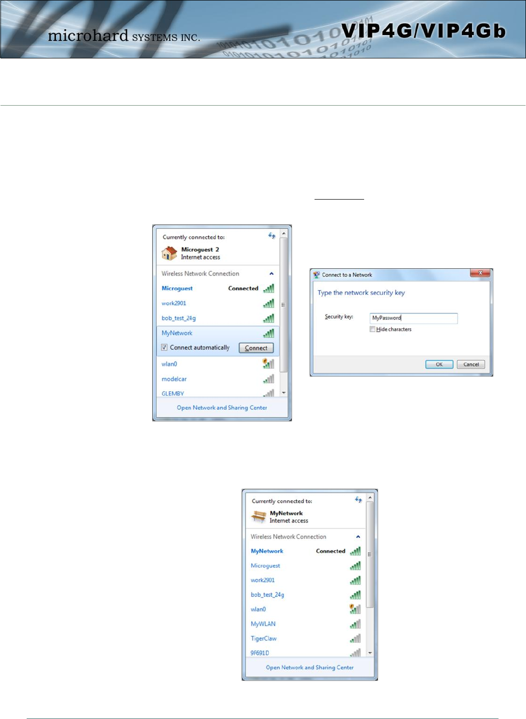
2.3.2 Connecting to WiFi
Now that the VIP4G has connection to the Cellular Carrier (See Section 2.2) and the WiFI
has been set up (See Section 2.3), WiFi devices should be able to detect and connect to
the VIP4G.
On a WiFi enabled PC/Device, the SSID of MyNetwork, that was created in the last exam-
ple should be visible. Connect to that SSID and enter the password.
Once connected the status should change to connected, and network access should be
enabled.
2.0 Quick Start
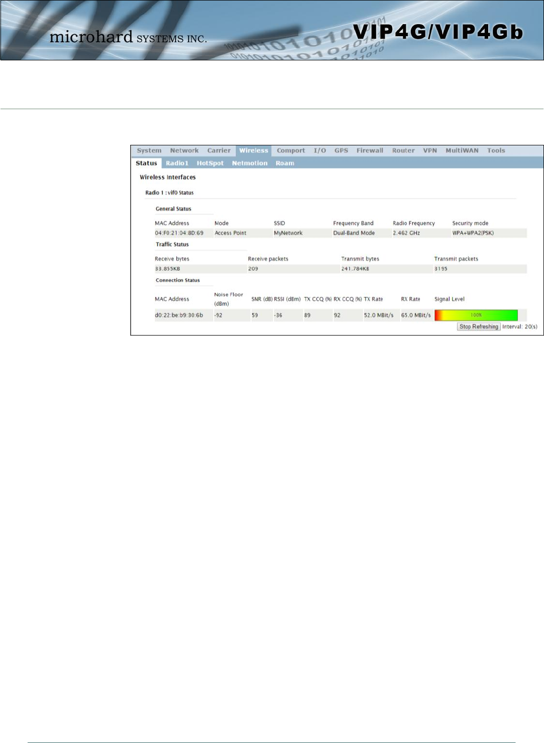
© Microhard Systems Inc. 19
The status of the WiFi connection should also be visible in the Wireless > Status tab in
the WebUI as seen below.
2.0 Quick Start
© Microhard Systems Inc. 20
3.0 Hardware Features
3.1 VIP4G
The VIP4G is a fully-enclosed unit ready to be interfaced to external devices.
VIP4G Hardware Features Include:
Standard Connectors for:
1 WAN Ethernet Ports (RJ45)
3 LAN Ethernet Ports (RJ45)
Data Port (RS232/DB9)
4-Pin: MATE-N-LOK Type Connector for Power
6-Pin: MATE-N-LOK Type Connector for RS485 Data
10-Pin: MATE-N-LOK Type Connector for Digital I/O
Cellular Antenna (SMA Female Antenna Connection x2)
WiFi Antenna (RP-SMA Female Antenna Connection x2)
Built in GPS (SMA Female Antenna Connection)
Status/Diagnostic LED’s for CPU, POWER, RSSI, RF_ACT, GPS, CELL_ACT
CFG Button for resetting to factory settings and firmware recovery operations
Mounting Holes/Tabs
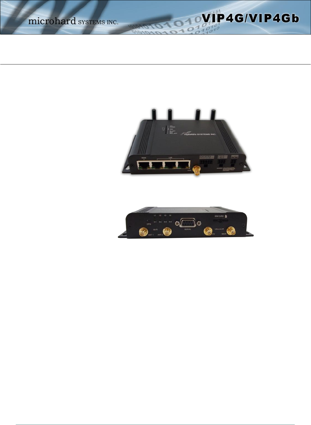
Image 3-1: Front View of VIP4G
Image 3-2: Rear View of VIP4G
© Microhard Systems Inc. 21
3.0 Hardware Features
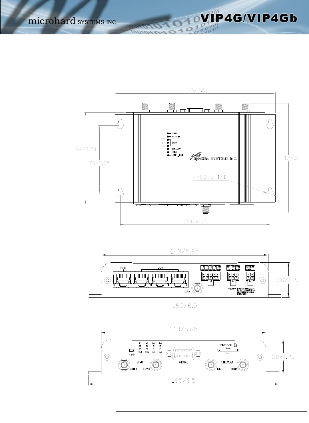
3.1.1 Mechanical Drawings
Drawing 3-1: VIP Top View Dimensions
Drawing 3-2: VIP Front View Dimensions
Drawing 3-3: VIP Rear View Dimensions
Note: All dimension units: Millimeter & Inches (mm/inches)
© Microhard Systems Inc. 22
3.0 Hardware Features
3.1.2 Connections
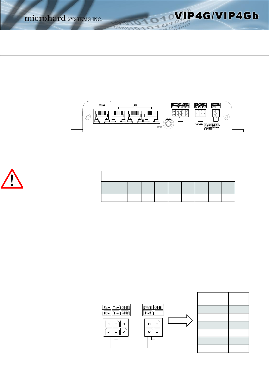
3.1.2.1 Front
On the front of the VIP4G Series are, from left to right:
WAN port
10/100/1000 Ethernet RJ45 Connection.
802.3af Passive PoE (WAN port only)
LAN port
3x - 10/100/1000 Ethernet RJ45 Connection.
GPS
SMA Female
Digital I/O Connector 10-Pin: (Use AMP MATE-N-LOK PN# 1-794617-0)
I-4, I-3, I-2, I-1, GND
O-4, O-3, O-2, O-1, GND
RS485/422 Connector 6-Pin: (Use AMP MATE-N-LOK PN# 794617-6)
Rx+, Tx+, GND
Rx-, Tx-, GND
Power Connector 4-Pin: (Use AMP MATE-N-LOK PN# 794617-4)
PWR, GND
IGN - Ignition signal for Power Saving Mode*
Caution: Using a
power supply that
does not provide
proper voltage may
damage the VIP4G
unit.
Drawing 3-4: VIP4G Front View
Ethernet RJ45 Connector Pin Number
Source
Voltage 1 2 3 4 5 6 7 8
9 - 30 Vdc Data Data Data DC+ DC+ Data DC- DC-
Table 3-1: WAN PoE Connections
Name Input or
Output
TxB (D+) O
TxA (D-) O
RxB (R+) I
RxA (R-) I
GND -
PWR + I
Table 3-2: Data RS422/485
Vin Pin Assignment
* Power Saving Mode only available on select units, must be
specified at time of order or returned to factory for upgrade.
© Microhard Systems Inc. 23
3.0 Hardware Features
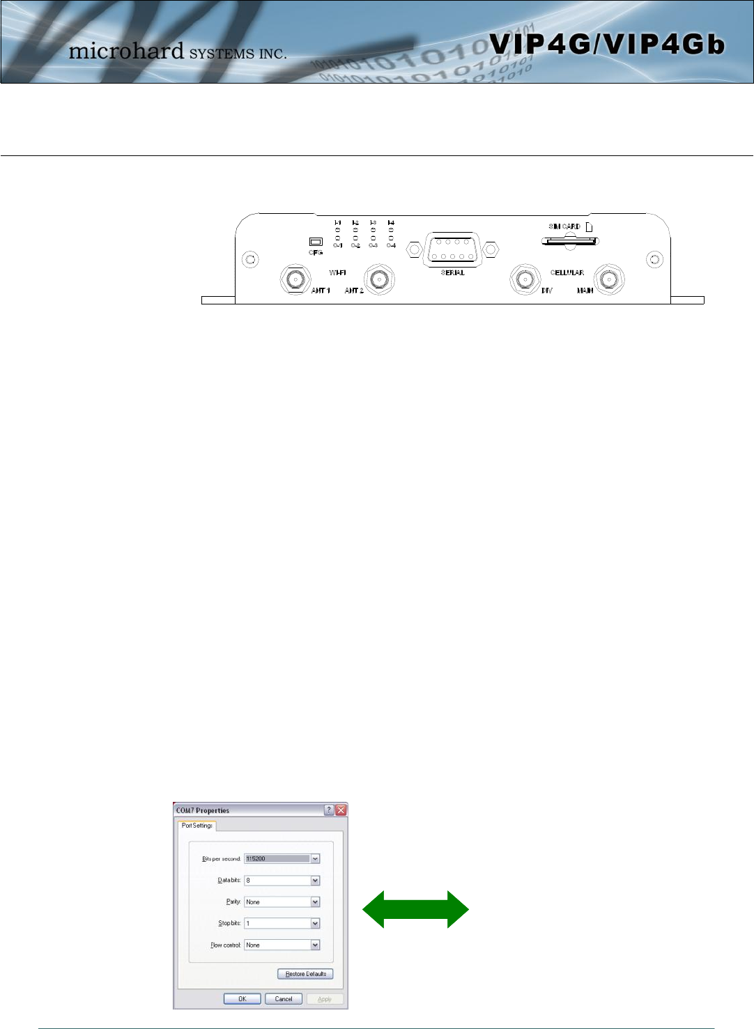
3.1.2.2 Rear
ANTENNA Connectors
The VIP4G uses female SMA antenna connectors for the Cellular and female RP-SMA connectors for the
WiFi antennas. Two antenna connections are provided for Wi-Fi, ANT1, and ANT2. Two connectors are
also provided for Cellular, MAIN and DIV.
Digital I/0 LED’s
The I-1, I-2, I-3, and I-4 LED’s indicate the status of the input pins on the digital I/O interface. The O-1, O-2,
O-3 and O-4 LED’s indicate the current state of the corresponding output relays.
Serial Port
The Serial port can be used for console type configuration (If disabled), or as a data communications port
for RS232 Devices.
CFG Button
Holding this button for 8 seconds while the VIP4G is powered up and running, will cause the unit to reset
and load factory default settings:
IP: 192.168.168.1 Subnet: 255.255.255.0
With these settings a web browser can be used to configure the unit.
Holding this button depressed while powering-up the VIP4G will boot the unit into FLASH FILE SYSTEM
RECOVERY mode. The default IP address for system recovery (only - not for normal access to the unit) is
static: 192.168.1.39.
Drawing 3-5: VIP4G Rear View
Default Console Port Settings:
Bits per Second: 115,200
Data Bits: 8
Parity: None
Stop bits: 1
Flow control: None
© Microhard Systems Inc. 24
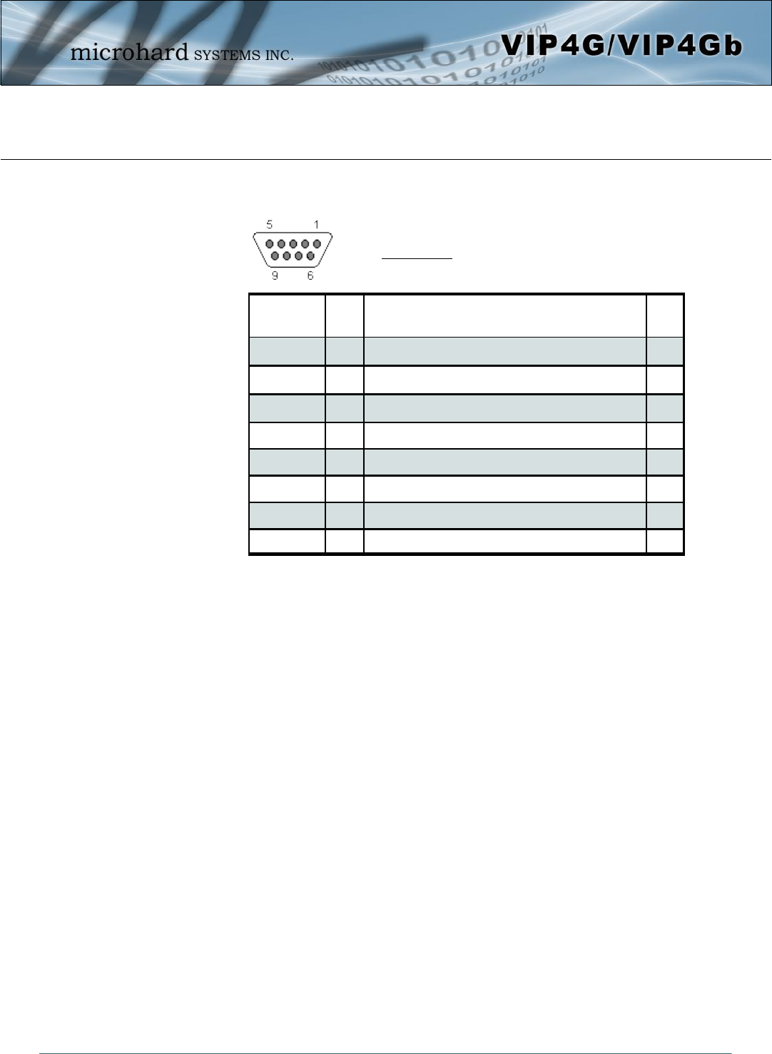
3.0 Hardware Features
Table 3-3: COM2 DB9 Pin Assignment
Pin Name No. Description In/
Out
DCD 1 Data Carrier Detect O
RXD 2 Receive Data O
TXD 3 Transmit Data I
DTR 4 Data Terminal Ready I
SG 5 Signal Ground
DSR 6 Data Set Ready O
RTS 7 Request To Send I
CTS 8 Clear To Send O
See Appendix A for a full description of the COM1 RS-
232 interface functions.
Serial Port (Continued)
SIM Card
This slot is used to install a SIM card provided by the cellular carrier to enable communication to their
cellular network. Ensure the SIM card is installed properly by paying attention to the diagram printed above
the SIM card slot.
© Microhard Systems Inc. 25
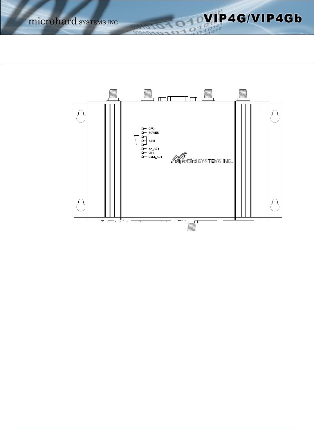
3.0 Hardware Features
3.1.3 Indicators
CPU (Blue)
ON indicates the CPU is running.
POWER (Red)
Illuminates when power is correctly applied to the unit.
RSSI (3 LEDs)
Indicate the received signal strength of the signal to the Cellular carrier. The number of LED’s illuminated
indicate the strength of the signal, with all 3 being illuminated representing a strong signal.
RF-ACT
The RF Activity LED illuminates when there is activity on the WiFi wireless interface.
GPS
Indicates that the GPS module is powered on and ready.
CELL_ACT
The CELL Activity LED illuminates when there is cellular activity.
Drawing 3-6: VIP4G Indicators
© Microhard Systems Inc. 26
4.0 Configuration
4.0 Web User Interface
Initial configuration of an VIP4G using the Web User (Browser) Interface (Web UI) method involves the
following steps:
configure a static IP Address on your PC to 192.168.168.10 (or any address on the 192.168.168.X
subnet other than the default IP of 192.168.168.1)
connect a VIP4G LAN ETHERNET port to PC NIC card using an Ethernet cable
apply power to the VIP4G and wait approximately 60 seconds for the system to load
open a web browser and enter the factory default IP address of the unit: 192.168.168.1
logon window appears; log on using default Username: admin Password: admin
use the web browser based user interface to configure the VIP4G as required.
refer to Section 2.0: Quick Start for step by step instructions.
In this section, all aspects of the Web Browser Interface, presented menus, and available configuration
options will be discussed.
Image 4-0-1: WebUI
© Microhard Systems Inc. 27
4.0 Configuration
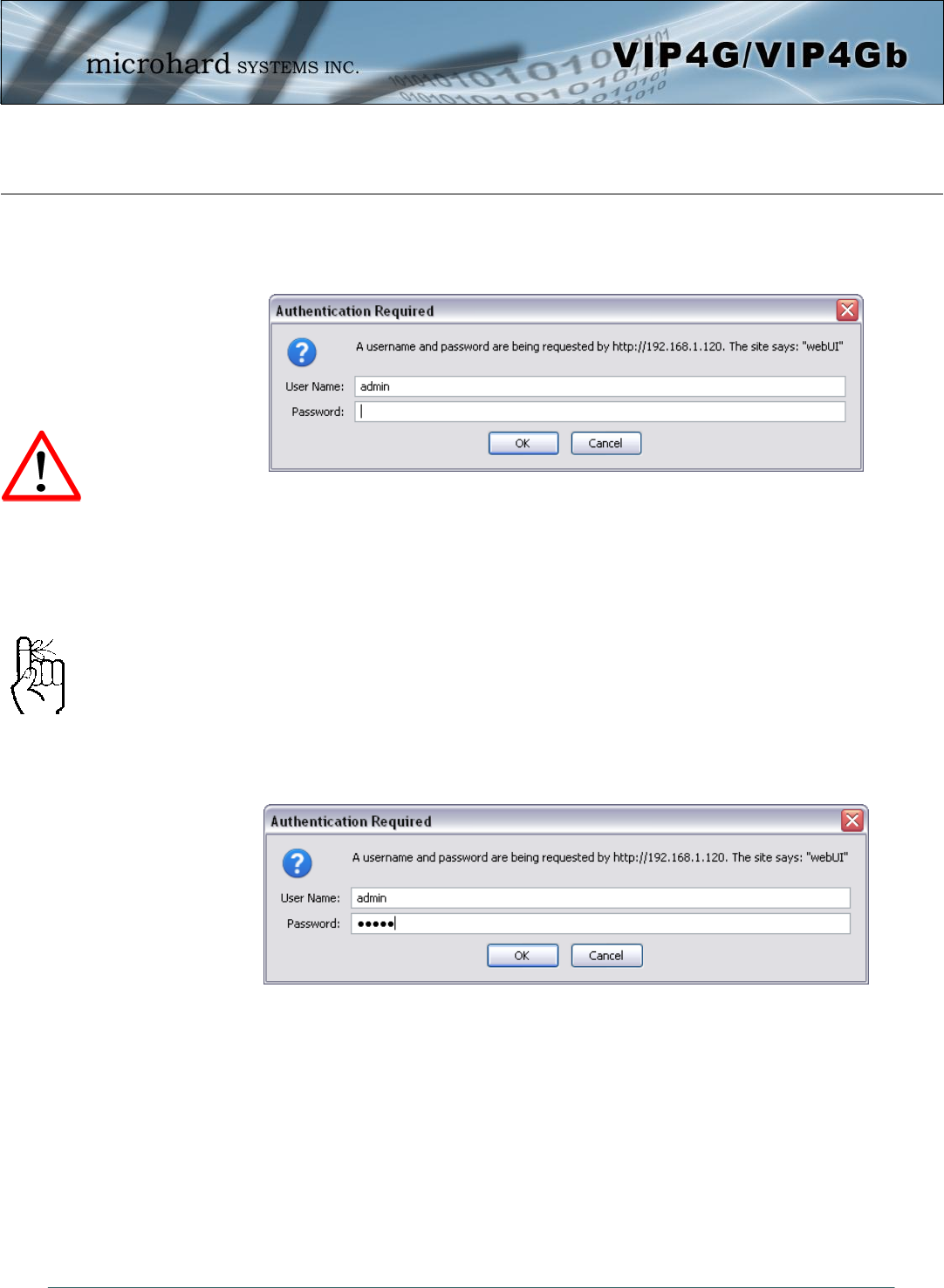
4.0.1 Logon Window
Upon successfully accessing the VIP4G using a Web Browser, the Logon window will appear.
The factory default User Name is: admin
The default password is: admin
Note that the password is case sensitive. It may be changed (discussed further along in this section), but
once changed, if forgotten, may not be recovered.
When entered, the password appears as ’dots’ as shown in the image below. This display format prohibits
others from viewing the password.
The ‘Remember my password’ checkbox may be selected for purposes of convenience, however it is
recommended to ensure it is deselected - particularly once the unit is deployed in the field - for one
primary reason: security.
Image 4-0-2: Logon Window
For security, do not allow the
web browser to remember the
User Name or Password.
It is advisable to change the
login Password. Do not
FORGET the new password
as it cannot be recovered.
Image 4-0-3: Logon Window : Password Entry
© Microhard Systems Inc. 28
4.0 Configuration
4.1 System
The main category tabs located at the top of the navigation bar separate the configuration of the VIP4G
into different groups based on function. The System Tab contains the following sub menu’s:
Summary - Status summary of entire radio including network settings,
version information, and radio connection status.
Settings - Host Name, Default System Mode (Bridge or Router),
System Time/Date, HTTP Port for the WebUI,
Access Control - Change passwords, create new users
Services - Enable/Disable RSSI LED’s, SSH and Telnet services
Maintenance - Version information, firmware Upgrades, reset to defaults,
configuration backup and restore.
Reboot - Remotely reboot the system.
Logout - Logout of the current browser session.
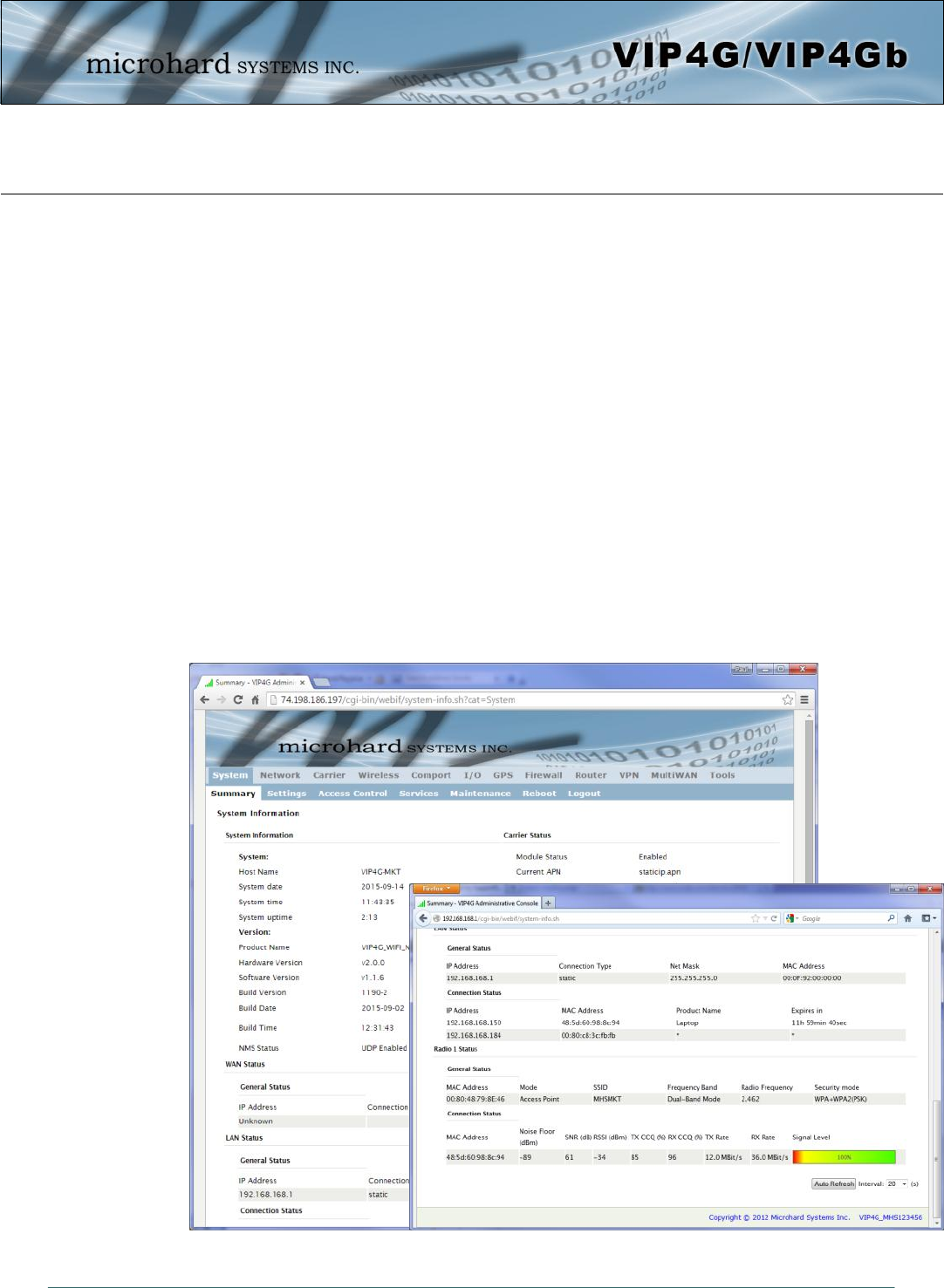
4.1.1 System > Summary
The System Summary screen is displayed immediately after initial login, showing a summary and status of
all the functions of the VIP4G in a single display. This information includes System Status, Carrier Status,
LAN & WAN network information, version info and WiFi radio status as seen below.
Image 4-1-1: System Info Window
© Microhard Systems Inc. 29
4.0 Configuration
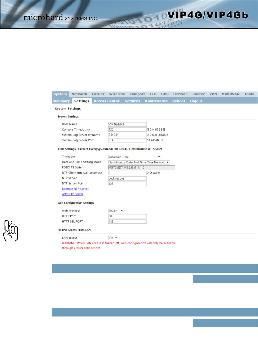
4.1.2 System > Settings
System Settings
Options available in the System Settings menu allow for the configuration of the Host Name.
Image 4-1-2: System Settings > System Settings
The Host Name is a convenient identifier for a specific VIP4G unit.
This feature is most used when accessing units remotely: a convenient
cross-reference for the unit’s WAN IP address. This name appears
when logged into a telnet session, or when the unit is reporting into
Microhard NMS System.
Host Name
Values (characters)
VIP4G (varies)
up to 30 characters
The Host Name must not be
confused with the Network
Name (SSID) (Wireless
Configuration menu). The
Network Name MUST be
exactly the same on each
wireless device within a VIP4G
network.
The console timeout is used to automatically logout a User, after the
specified time period of inactivity, on the console port. This affects
bother the serial console port or a TCP/IP telnet session.
Console Timeout
Values (seconds)
120
© Microhard Systems Inc. 30
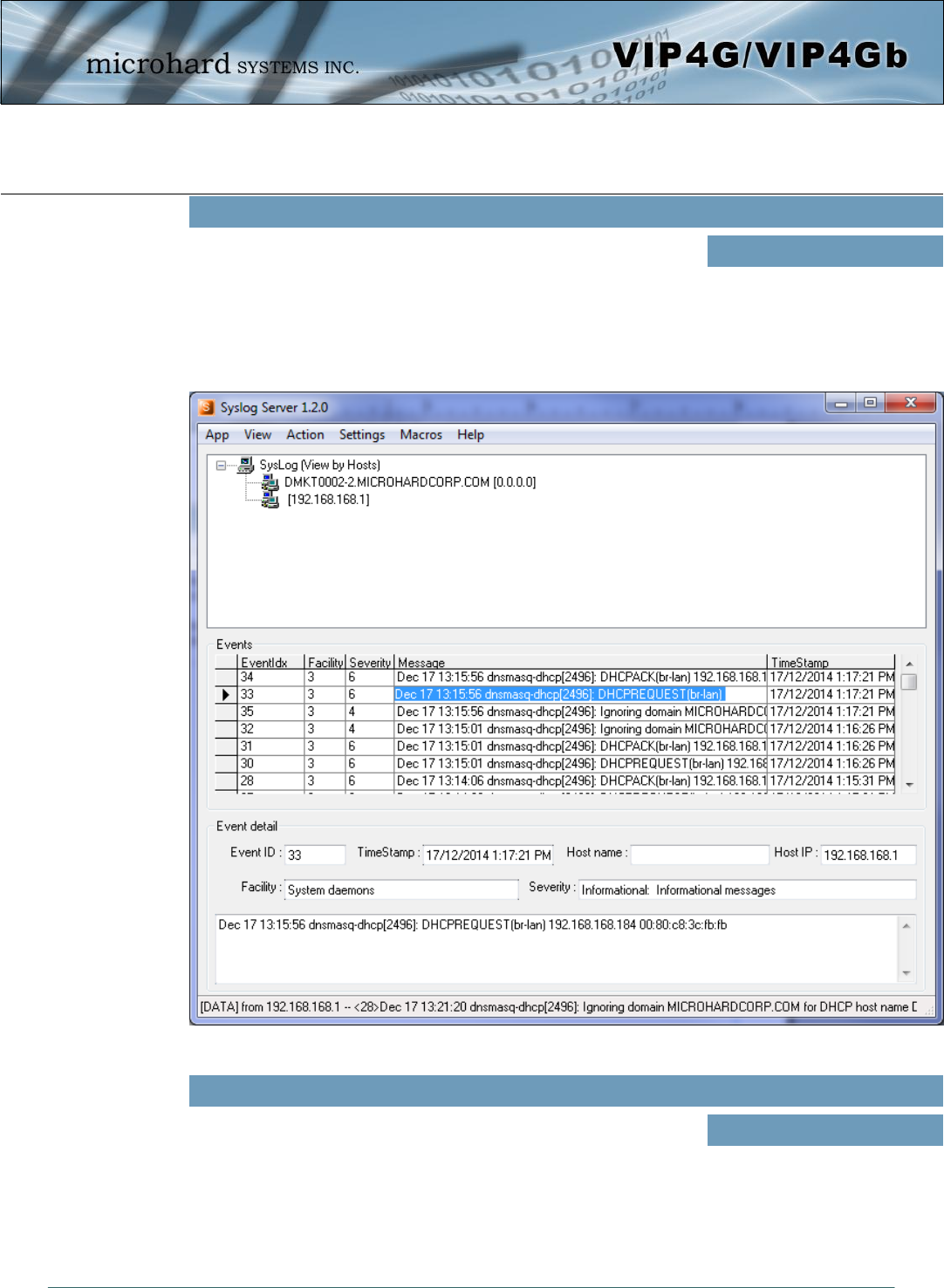
4.0 Configuration
The modem can be configured to report system level events to a third
party Syslog server, as shown below. Syslog data can then be filtered
and depending on the features of the Syslog server application, alerts
can be generated accordingly.
The screenshot below shows a sample from a simple Syslog Server
application.
System Log Server IP/Name
Values
0.0.0.0
Enter the UDP port number on the Syslog Server where the actual
service is running. Consult with the documentation of your chosen
Syslog Server for the correct port number. The most common port is
514, which has been set as the default.
System Log Server Port
Values (UDP Port #)
514
Image 4-1-3: System Settings > Syslog Server Example
© Microhard Systems Inc. 31
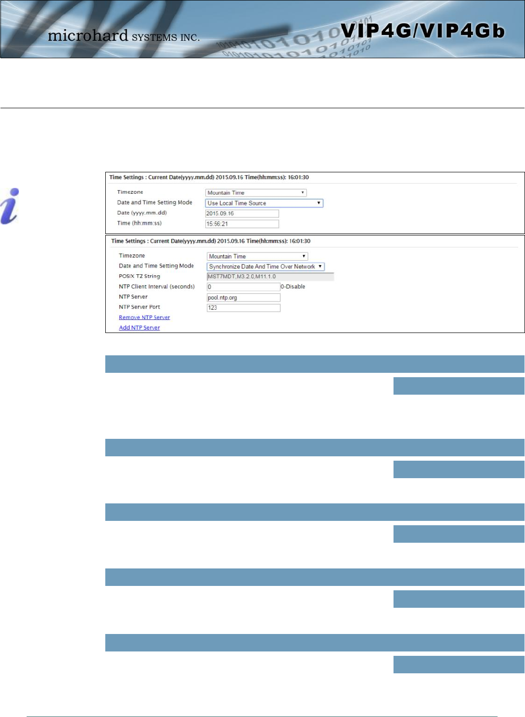
4.0 Configuration
Date
The calendar date may be entered in this field. Note that the entered
value is lost should the VIP4G lose power for some reason. Values (yyyy-mm-dd)
2011.04.01 (varies)
Time
The time may be entered in this field. Note that the entered value is
lost should the VIP4G lose power for some reason. Values (hh:mm:ss)
11:27:28 (varies)
Image 4-1-3: System Settings > Time Settings
Network Time Protocol (NTP)
can be used to synchronize the
time and date or computer
systems with a centralized,
referenced server. This can
help ensure all systems on a
network have the same time
and date.
Date and Time Setting Mode
Select the Date and Time Setting Mode required. If set for ‘Use Local
Time’ the unit will keep its own time and not attempt to synchronize
with a network server. If ‘Synchronize Date And Time Over Network’ is
selected, a NTP server can be defined.
Values (selection)
Use Local Time Source
Synchronize Date And Time
Over Network
If connecting to a NTP time server, specify the timezone from the
dropdown list. Values (selection)
User Defined (or out of date)
Timezone
POSIX TZ String
This displays the POSIX TZ String used by the unit as determined by
the timezone setting. Values (read only)
(varies)
Time Settings
The VIP4G can be set to use a local time source, thus keeping time on its own, or it can be configured to
synchronize the date and time via a NTP Server. The options and menus available will change depending
on the current setting of the Date and Time Setting Mode, as seen below.
© Microhard Systems Inc. 32
4.0 Configuration
NTP Server
Enter the IP Address or domain name of the desired NTP time server. Values (address)
pool.ntp.org
NTP Port
Enter the IP Address or domain name of the desired NTP time server. Values (port#)
123
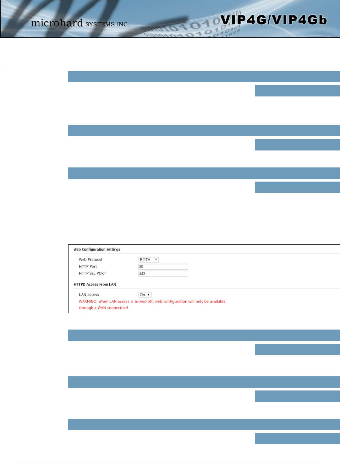
Web Configuration Settings
The last section of the System Setting menu allows the configuration of the HTTP and HTTPS Ports used
for the web server of the WEBUI.
Image 4-1-4: System Settings > Web Configuration Settings
HTTP Port
The default web server port for the web based configuration tools used
in the VIP4G is port 80. If a non standard port is used, it must be
specified in a internet browser to access the unit. (example:
http://192.168.168.1:8080)
Values (port#)
80
HTTP SSL Port
The secure web port (HTTPS) can be enabled or disabled using the
HTTP SSL On/Off drop down menu. If enabled, the port used can be
specified, the default is port 443.
Values (port#)
443
LAN Access
This option can be used to disable LAN access of the HTTP WebUI
port. If disabled, connection can only be made from the WAN side
(Wired or 4G).
Values (selection)
On / Off
NTP Client Interval
Specify the frequency, in seconds, in which the VIP4G will synchronize
its time and date with the specified NTP Server. If disabled the VIP4G
will only sync to an NTP Server during boot-up. *Please note: Each
time the VIP4G synchronizes with a NTP Server, cellular data may
be consumed*
Values (seconds)
0
© Microhard Systems Inc. 33
4.0 Configuration
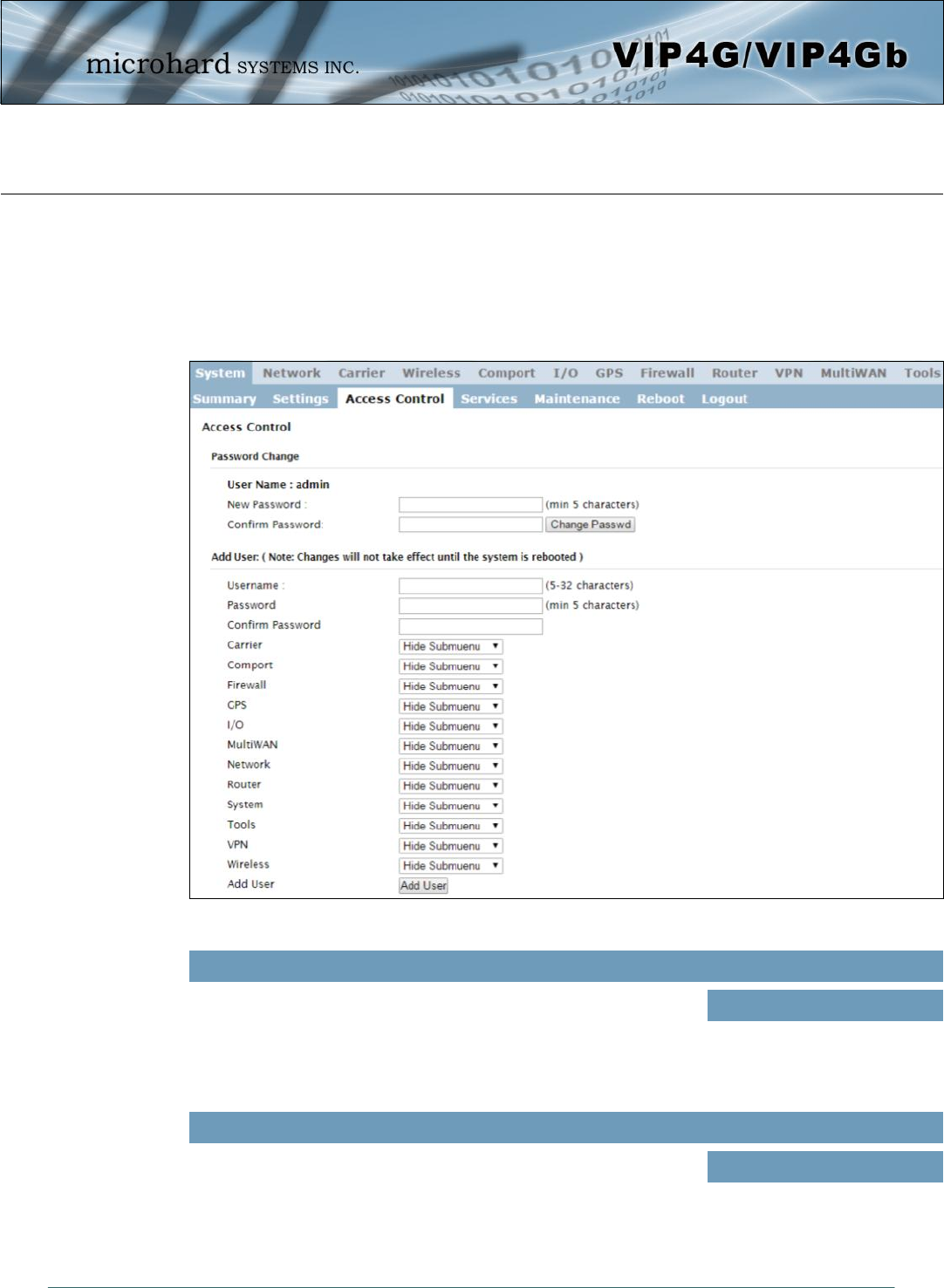
4.1.3 System > Access Control
Password Change
The Password Change menu allows the password of the user ‘admin’ to be changed. The ‘admin’
username cannot be deleted, but additional users can be defined and deleted as required as seen in the
Users menu below.
Image 4-1-5: Access Control > Password Change
Enter a new password for the ‘admin’ user. It must be at least 5
characters in length. The default password for ‘admin’ is ‘admin’.
New Password
Values (characters)
admin
min 5 characters
Confirm Password
The exact password must be entered to confirm the password change,
if there is a mistake all changes will be discarded.
admin
min 5 characters
Values (characters)
© Microhard Systems Inc. 34
4.0 Configuration
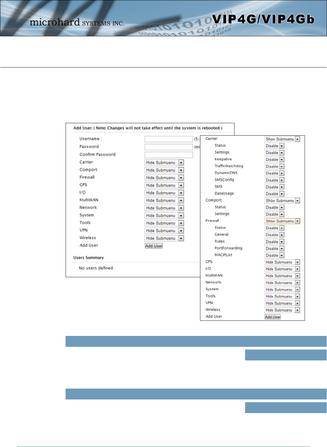
4.1.3 System > Access Control
Users
Different users can be set up with customized access to the WebUI. Each menu or tab of the WebUI can
be disabled on a per user basis as seen below.
Image 4-1-6: Access Control > Users
Enter the desired username. Minimum or 5 character and maximum of
32 character. Changes will not take effect until the system has been
restarted.
Username
Values (characters)
(no default)
Min 5 characters
Max 32 characters
Password / Confirm Password
Passwords must be a minimum of 5 characters. The Password must
be re-entered exactly in the Confirm Password box as well.
(no default)
min 5 characters
Values (characters)
© Microhard Systems Inc. 35
4.0 Configuration
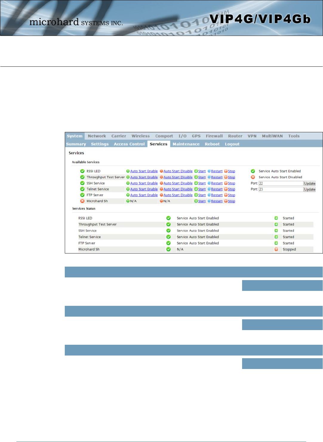
4.1.4 System > Services
Available Services
Certain services in the VIP4G can be disabled or enabled for either security considerations or resource/
power considerations. The Enable/Disable options are applied after a reboot and will take affect after each
start up. The Start/Restart/Stop functions only apply to the current session and will not be retained after a
power cycle.
Image 4-1-7: System > Services
The VIP4G has the ability to turn off the RSSI LED’s. The RSSI value
can still be read from the unit, but the status will not be visible on the
unit itself .
RSSI LED
Values (selection)
Enable / Disable
Throughput Test Server
For testing purposes the VIP4G has an internal iperf server that can be
used to test unit performance. The user must install a iperf client to
use this functionality. Enable / Disable
Values (selection)
SSH Service
Using the SSH Service Enable/Disable function, you can disable the
SSH service (Port 22) from running on the VIP4G. You can also
specify a alternate port to use. Any port number changes require the
modem to be restarted. Enable / Disable
Values (selection)
© Microhard Systems Inc. 36
4.0 Configuration
Telnet Service
Using the Telnet Service Enable/Disable function, you can disable the
Telnet service (Port 23) from running on the VIP4G. You can also
specify a alternate port to use. Any port number changes require the
modem to be restarted. Enable / Disable
Values (characters)
Using the FTP Service Enable/Disable function, you can disable the
FTP service (Port 21) from running on the VIP4G. This port is reserved
for internal use / future use.
FTP Server
Values (selection)
Start / Restart / Stop
Microhard Sh
Custom SSH Port. Reserved for internal use.
Start / Restart / Stop
Values (selection)
© Microhard Systems Inc. 37
4.0 Configuration
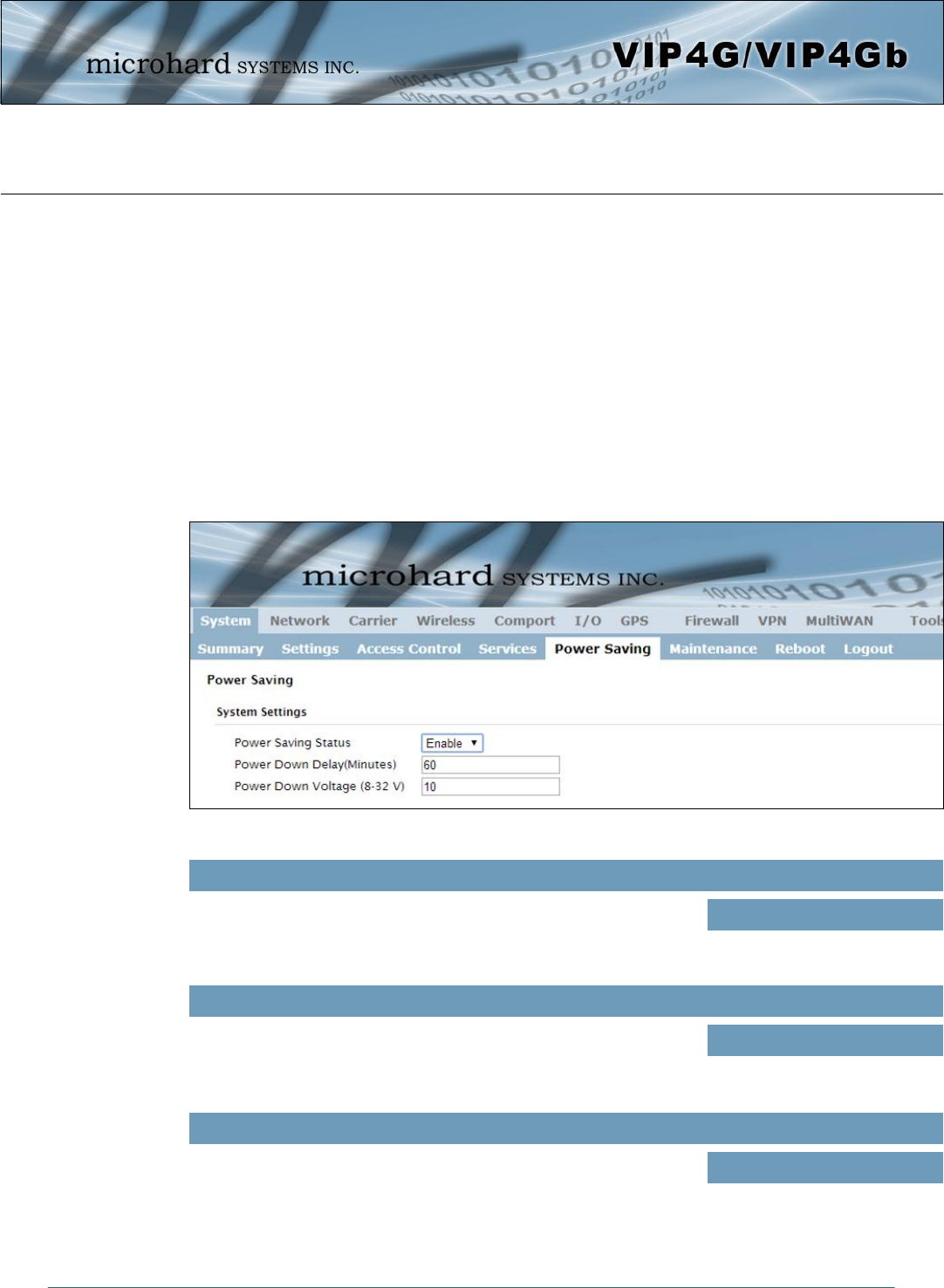
4.1.5 System > Power Saving (Factory Installed Option)
The Power Saving feature of the VIP4G is only available in firmware version 1.1.6-1170 or later. It
also requires a factory installed modification that must be specified at the time of order, or returned
to the factory for an upgrade.
The Power Saving feature of the VIP4G works with the IGN line located on the PWR connector. It was
designed with vehicle systems in mind, but could be useful in other applications. The VIP4G must run for at
least 5 minutes before power saving will work.
The VIP4G requires that the IGN line be ON (1.8 - 32V) to boot up and perform normal operations. If the
IGN line goes OFF (Less than 1.8V) or floating (The Ignition of the vehicle turned OFF), the VIP4G will
then look at the Power Down Delay and start counting down to when it will turn itself off. It will also look at
the Power Down Voltage, if the voltage drops below the set value, the VIP4G will power down.
The VIP4G will power up and resume normal operation once the IGN line is retuned to the ON state.
Image 4-1-8: System > Power Saving
Enable or disable the power saving feature of the VIP4G. If enabled, it
requires that the IGN line is high to run, if IGN is low it will initiate the
power down delay.
Power Saving Status
Values (selection)
Enable / Disable
Power Down Delay
Once the VIP4G is running for at least five minutes, and the IGN line
goes low (less than 1.8V), the VIP4G will stay on for the amount of
time (minutes) defined here. 60
Values (minutes)
Power Down Voltage
The VIP4G can be configured to power down if the supply voltage
drops below the value defined here. This ensures that the unit will
power down before it causes a significant drain on the vehicles battery. 10
Values (8 - 32 V))
© Microhard Systems Inc. 38
4.0 Configuration
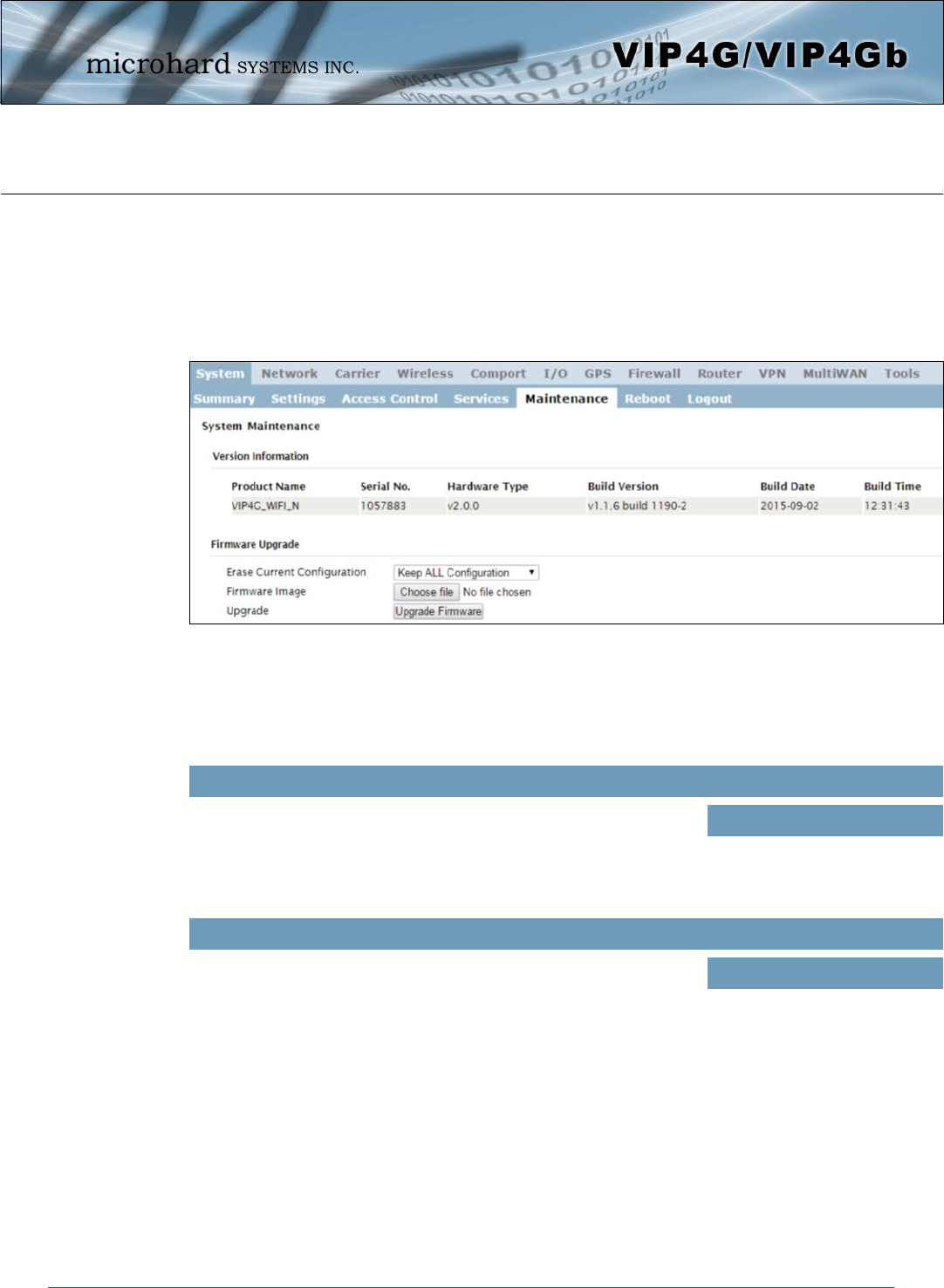
4.1.6 System > Maintenance
Version Information
Detailed version information can be found on this display. The Product Name, Firmware Version, Hardware
Type, Build Version, Build Date and Build Time can all be seen here, and may be requested from
Microhard Systems to provide technical support.
Image 4-1-9: Maintenance > Version Information / Firmware Upgrade
Allows a user to select if the unit is to keep its current configuration,
erase its configuration, or to erase the configuration, but keep Carrier
Settings during the firmware upgrade process.
Erase Current Configuration
Values (selection)
Keep ALL Configuration
Keep Carrier Configuration
Erase Configuration
Firmware Image
Use the Browse button to find the firmware file supplied by Microhard
Systems. Select “Upgrade Firmware” to start the upgrade process.
This can take several minutes. (no default)
Values (file)
Firmware Upgrade
Occasional firmware updates may be releases by Microhard Systems which include fixes and new
features. The firmware can be updated here wirelessly using the WebUI.
© Microhard Systems Inc. 39
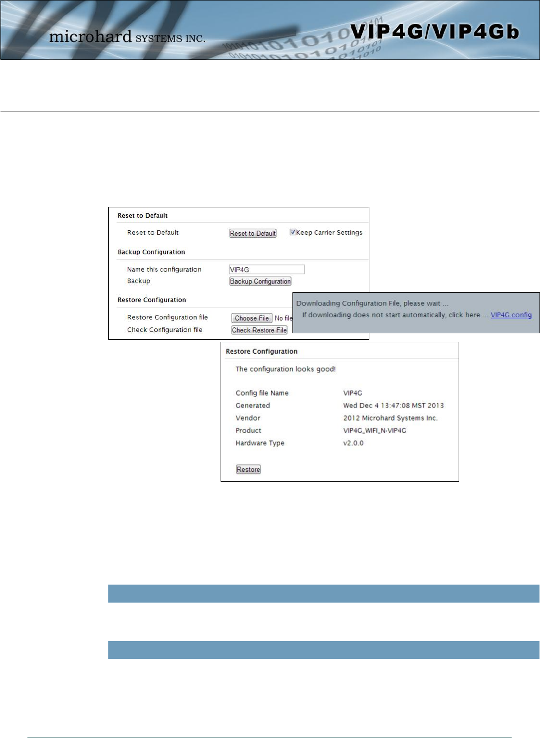
4.0 Configuration
4.1.6 System > Maintenance
Reset to Default
The VIP4G may be set back to factory defaults by using the Reset to Default option under System >
Maintenance > Reset to Default. *Caution* - All settings will be lost!!!
Image 4-1-10: Maintenance > Reset to Default / Backup & Restore Configuration
Use this field to name the configuration file. The .config extension will automatically be added to the
configuration file.
Name this Configuration / Backup Configuration
Restore Configuration file / Check Restore File / Restore
Use the ‘Browse’ button to find the backup file that needs to be restored to the unit. Use the ‘Check
Restore File’ button to verify that the file is valid, and then the option to restore the configuration is
displayed, as seen above.
Backup & Restore Configuration
The configuration of the VIP4G can be backed up to a file at any time using the Backup Configuration
feature. The file can the be restored using the Restore Configuration feature. It is always a good idea to
backup any configurations in case of unit replacement. The configuration files cannot be edited offline, they
are used strictly to backup and restore units.
© Microhard Systems Inc. 40
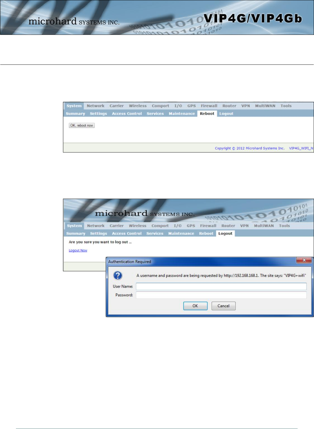
4.0 Configuration
4.1.7 System > Reboot
The VIP4G can be remotely rebooted using the System > Reboot menu. As seen below a button ‘OK,
reboot now’ is provided. Once pressed, the unit immediately reboots and starts its boot up procedure.
Image 4-1-11: System > Reboot
4.1.8 System > Logout
The logout function allows a user to end the current configuration session and prompt for a login screen.
Image 4-1-12: System > logout
© Microhard Systems Inc. 41
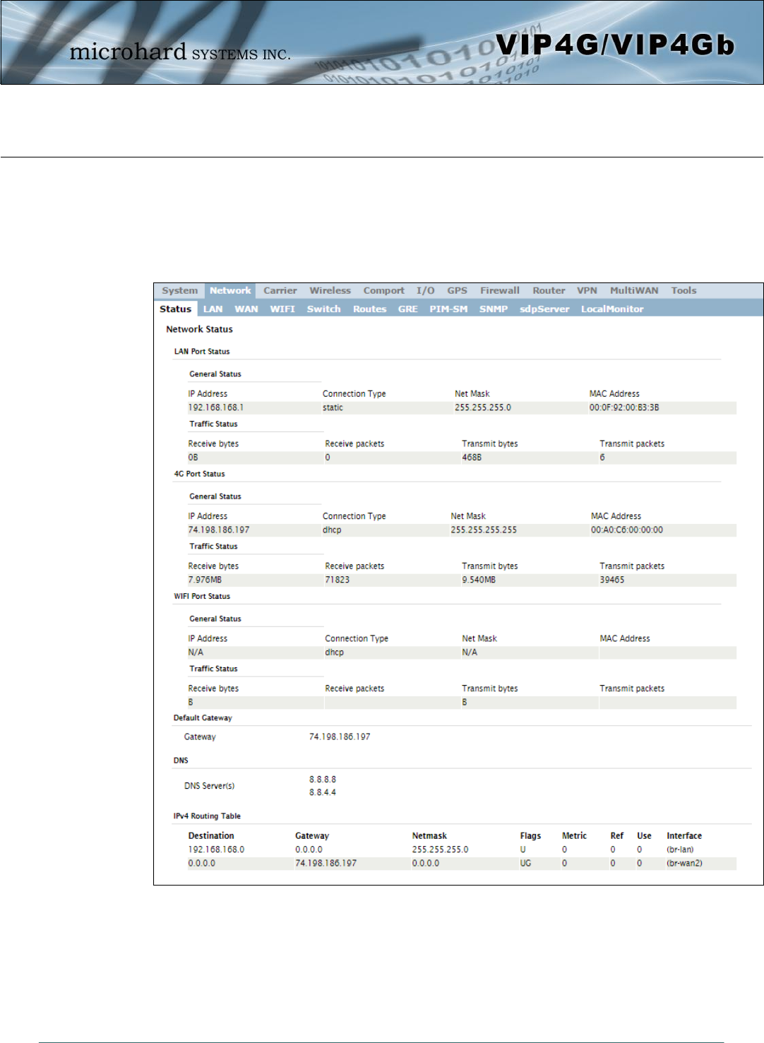
4.0 Configuration
4.2 Network
4.2.1 Network > Status
The Network Status display gives a overview of the currently configured network interfaces including the
Connection Type (Static/DHCP), IP Address, Net Mask, Default Gateway, DNS, and IPv4 Routing Table.
Image 4-2-1: Network > Network Status
© Microhard Systems Inc. 42
4.0 Configuration
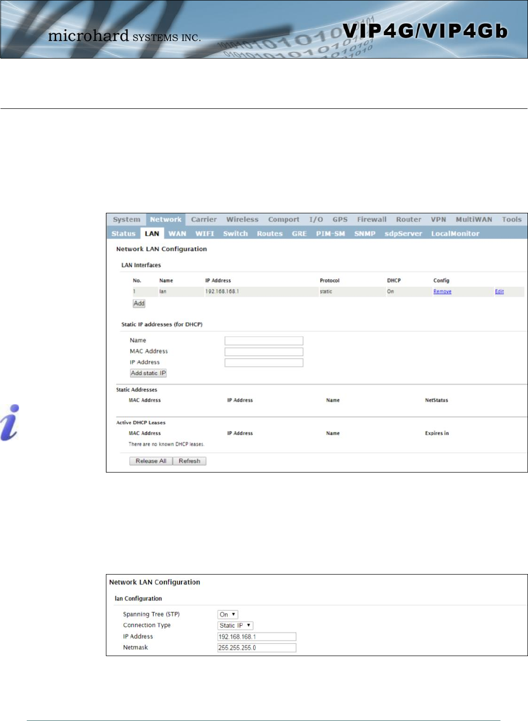
4.2.2 Network > LAN
Network LAN Configuration
The Ethernet port (RJ45) on the back of the VIP4G is the LAN port, used for connection of devices on a
local network. By default, this port has a static IP Address of 192.168.168.1. It also, by default is running a
DHCP server to provide IP Addresses to devices that are connected to the physical port, and devices
connected by a WiFi connection (if equipped).
Image 4-2-2: Network > LAN Configuration
DHCP: Dynamic Host
Configuration Protocol may
be used by networked
devices (Clients) to obtain
unique network addresses
from a DHCP server.
Advantage:
Ensures unique IP addresses
are assigned, from a central
point (DHCP server) within a
network.
Disadvantage:
The address of a particular
device is not ‘known’ and is
also subject to change.
STATIC addresses must be
tracked (to avoid duplicate
use), yet they may be
permanently assigned to a
device.
Image 4-2-3: Network > Add/Edit LAN Interface
LAN Add/Edit Interface
The VIP4G has the capability to have multiple SSID’s for the WiFi radio (optional). New Interfaces can be
added for additional SSID’s, providing, if required, separate subnets for each SSID. By default any
additional interfaces added will automatically assign IP addresses to connecting devices via DHCP.
Additional interfaces can only be used by additional WIFI SSID’s (virtual interfaces).

© Microhard Systems Inc. 43
4.0 Configuration
This selection determines if the VIP4G will obtain an IP address from a
DHCP server on the attached network, or if a static IP address will be
entered. If a Static IP Address is chosen, the fields that follow must
also be populated.
Connection Type
Values (selection)
DHCP
Static
Within any IP network, each
device must have its own
unique IP address.
If ‘Static’ Connection Type is selected, a valid IPv4 Address for the
network being used must be entered in the field. If ‘DHCP’ is chosen
this field will not appear and it will be populated automatically from the
DHCP server.
IP Address
Values (IP Address)
192.168.168.1
If ‘Static’ Connection Type is selected, the Network Mask must be
entered for the Network. If ‘DHCP’ is chosen this field will not appear
and it will be populated automatically from the DHCP server.
Netmask
Values (IP Address)
255.255.255.0
A SUBNET MASK is a bit
mask that separates the
network and host (device)
portions of an IP address.
The ‘unmasked’ portion
leaves available the
information required to
identify the various devices
on the subnet.
Use this option to enable or disable the use of Spanning Tree Protocol
(STP).
Spanning Tree (STP)
Values (selection)
On
Off
© Microhard Systems Inc. 44
4.0 Configuration
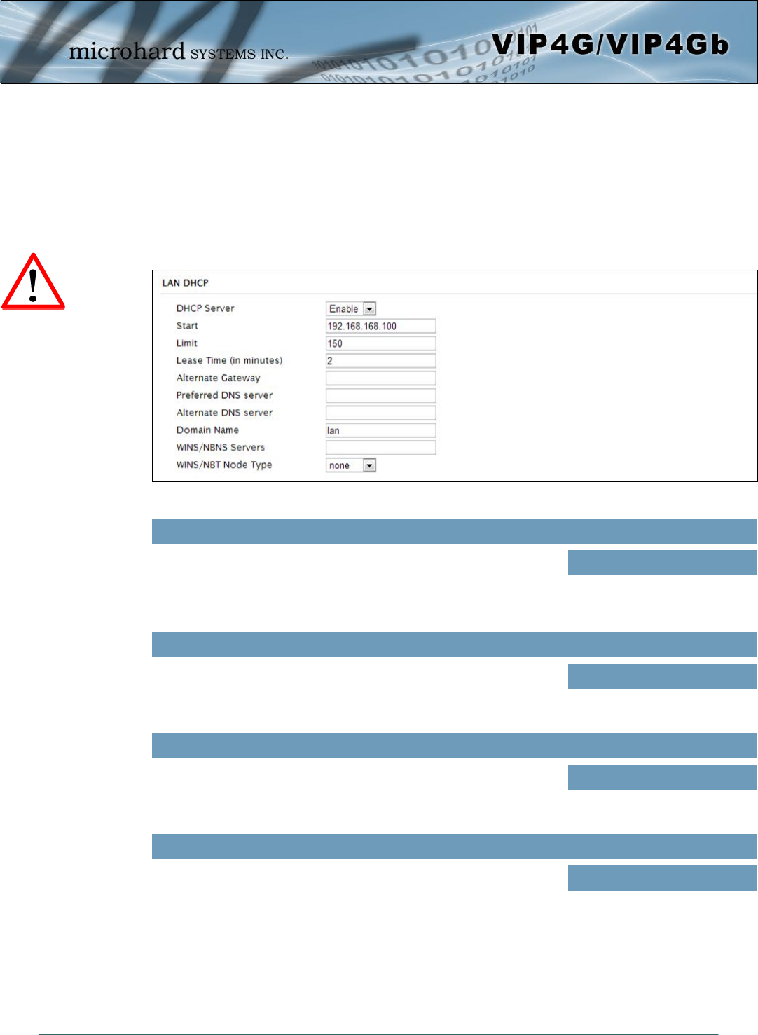
LAN DHCP
A VIP4G may be configured to provide dynamic host control protocol (DHCP) service to all attached (either
wired or wireless (WiFi)-connected) devices. By default the DHCP service is enabled, so devices that are
connected to the physical Ethernet LAN ports, as well as any devices that are connected by WiFi will be
assigned an IP by the VIP4G.
The option is used to enable or disable the DHCP service for devices
connected to the LAN Port and devices connected through a Wireless
connection. This includes VIP connected as clients and other wireless
devices such as 802.11 connections.
DHCP
Values (selection)
On / Off
Select the starting address DHCP assignable IP Addresses. The first
octets of the subnet will be pre-set based on the LAN IP configuration,
and can not be changed.
Start
Values (IP Address)
192.168.168.100
Image 4-2-4: Network > Add/Edit Interface DHCP
Set the maximum number of IP addresses that can be assigned by the
VIP4G.
Limit
Values (integer)
150
The DHCP lease time is the amount of time before a new request for a
network address must be made to the DHCP Server.
Lease Time
Values (minutes)
(minutes)
Prior to enabling this service,
verify that there are no other
devices - either wired (e.g.
LAN) or wireless (e.g. another
VIP Series unit) with an active
DHCP SERVER service.
(The Server issues IP
address information at the
request of a DHCP Client,
which receives the
information.)
© Microhard Systems Inc. 45
4.0 Configuration
Specify an alternate gateway for DHCP assigned devices if the default
gateway is not to be used.
Alternate Gateway
Values (IP Address)
(IP Address)
Specify a preferred DNS server address to be assigned to DHCP
devices.
Preferred DNS Server
Values (IP Address)
(IP Address)
Specify the alternate DNS server address to be assigned to DHCP
devices.
Alternate DNS Server
Values (IP Address)
(IP Address)
Enter the Domain Name for the DHCP devices.
Domain Name
Values (string)
(IP Address)
Enter the address of the WINS/NBNS (NetBIOS) Server. The WINS
server will translate computers names into their IP addresses, similar
to how a DNS server translates domain names to IP addresses.
WINS/NBNS Servers
Values (IP/Domain)
(no default)
Select the method used to resolve computer names to IP addresses.
Four name resolution methods are available:
B-node: broadcast
P-node: point-to-point
M-node: mixed/modified
H-node: hybrid
WINS/NBT Node Type
Values (selection)
none
b-node
p-node
m-node
h-node
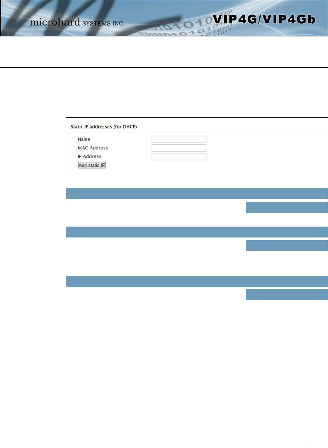
© Microhard Systems Inc. 46
4.0 Configuration
The name field is used to give the device a easily recognizable name.
Name
Values (characters)
(no default)
Static IP Addresses (for DHCP)
In some applications it is important that specific devices always have a predetermined IP address. This
section allows for MAC Address binding to a IP Address, so that whenever the device that has the
specified MAC address, will always get the selected IP address. In this situation, all attached (wired or
wireless) devices can all be configured for DHCP, but still get a known IP address.
Enter in the MAC address of the device to be bound to a set IP
address. Set the IP Address in the next field. Must use the format:
AB:CD:DF:12:34:D3. It is not case sensitive, but the colons must be
present.
MAC Address
Values (MAC Address)
(no default)
Enter the IP Address to be assign to the device specified by the MAC
address above.
IP Address
Values (IP Address)
(minutes)
Static Addresses
This section displays the IP address and MAC address currently assigned through the DCHP service, that
are bound by it’s MAC address. Also shown is the Name, and the ability to remove the binding by clicking
“Remove _______”.
Active DHCP Leases
This section displays the IP Addresses currently assigned through the DCHP service. Also shown is the
MAC Address, Name and Expiry time of the lease for reference.
Network Interfaces
When additional Network Interfaces are added, they will show up here in a list. You can remove Network
Interfaces by clicking “Remove _______”.
Image 4-2-5: Network > MAC Address Binding
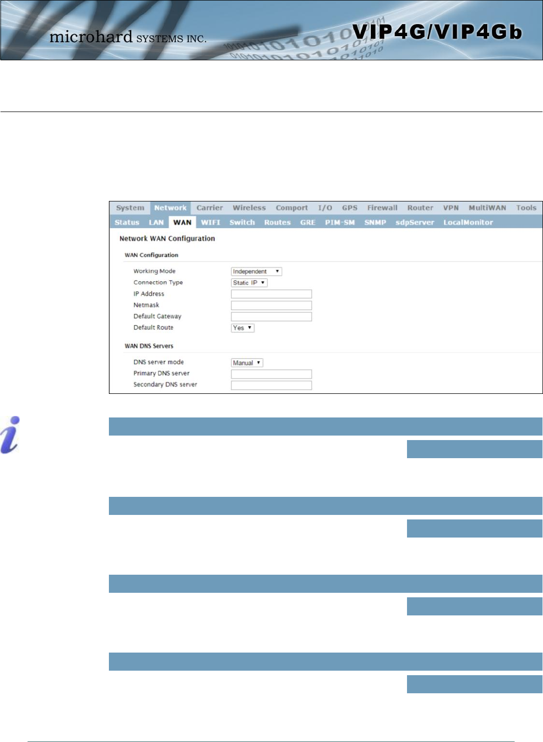
© Microhard Systems Inc. 47
4.0 Configuration
4.2.3 Network > WAN
WAN Configuration
The WAN configuration refers to the wired WAN connection on the VIP4G. The WAN port can be used to
connect the VIP4G to other networks, the internet and/or other network resources.
This selection determines if the VIP4G will obtain an WAN IP address
from a DHCP server, or if a static IP address will be entered. If a Static
IP Address is chosen, the fields that follow must also be populated.
Connection Type
Values (selection)
DHCP
Static
DHCP: Dynamic Host
Configuration Protocol may
be used by networked
devices (Clients) to obtain
unique network addresses
from a DHCP server.
Advantage:
Ensures unique IP addresses
are assigned, from a central
point (DHCP server) within a
network.
Disadvantage:
The address of a particular
device is not ‘known’ and is
also subject to change.
STATIC addresses must be
tracked (to avoid duplicate
use), yet they may be
permanently assigned to a
device.
Image 4-2-6: Network > WAN Configuration
If ‘Static’ Connection Type is selected, a valid IPv4 Address for the
network being used must be entered in the field. If ‘DHCP’ is chosen
this field will not appear and it will be populated automatically from the
DHCP server.
IP Address
Values (IP Address)
(no default)
If ‘Static’ Connection Type is selected, the Network Mask must be
entered for the Network. If ‘DHCP’ is chosen this field will not appear
and it will be populated automatically from the DHCP server.
Netmask
Values (IP Address)
(no default)
Use this to set the function of the physical WAN RJ45 port. If set to
independent, the physical WAN port will operate as a standard WAN
port, if disabled, the physical port will operate as another LAN port on
the LAN.
Working Mode
Values (selection)
Independent
Bridge to LAN
© Microhard Systems Inc. 48
4.0 Configuration
If the VIP4G is integrated into a network which has a defined gateway,
then, as with other hosts on the network, this gateway’s IP address will
be entered into this field. If there is a DHCP server on the network,
and the Connection Type (see previous page) is selected to be DHCP,
the DHCP server will populate this field with the appropriate gateway
address.
Default Gateway
Values (IP Address)
(no default)
DNS (Domain Name Service) Servers are used to resolve domain
names into IP addresses. If the DNS server mode is set for Auto the
DHCP server will populate this field and the value set can be viewed
on the Network > Status page.
Primary/Secondary DNS Servers
Values (IP Address)
(no default)
The WAN can be added as the default route for all traffic exiting the
modem (unless specified otherwise in the Routes menu).
Default Route
Values (selection)
Yes / No
Select between Auto and Manual for the WAN DNS Services. If set to
auto it will be population by the ISP, if set the manual up to (2) DNS
servers can be specified.
DNS server mode
Values (selection)
Auto / Manual
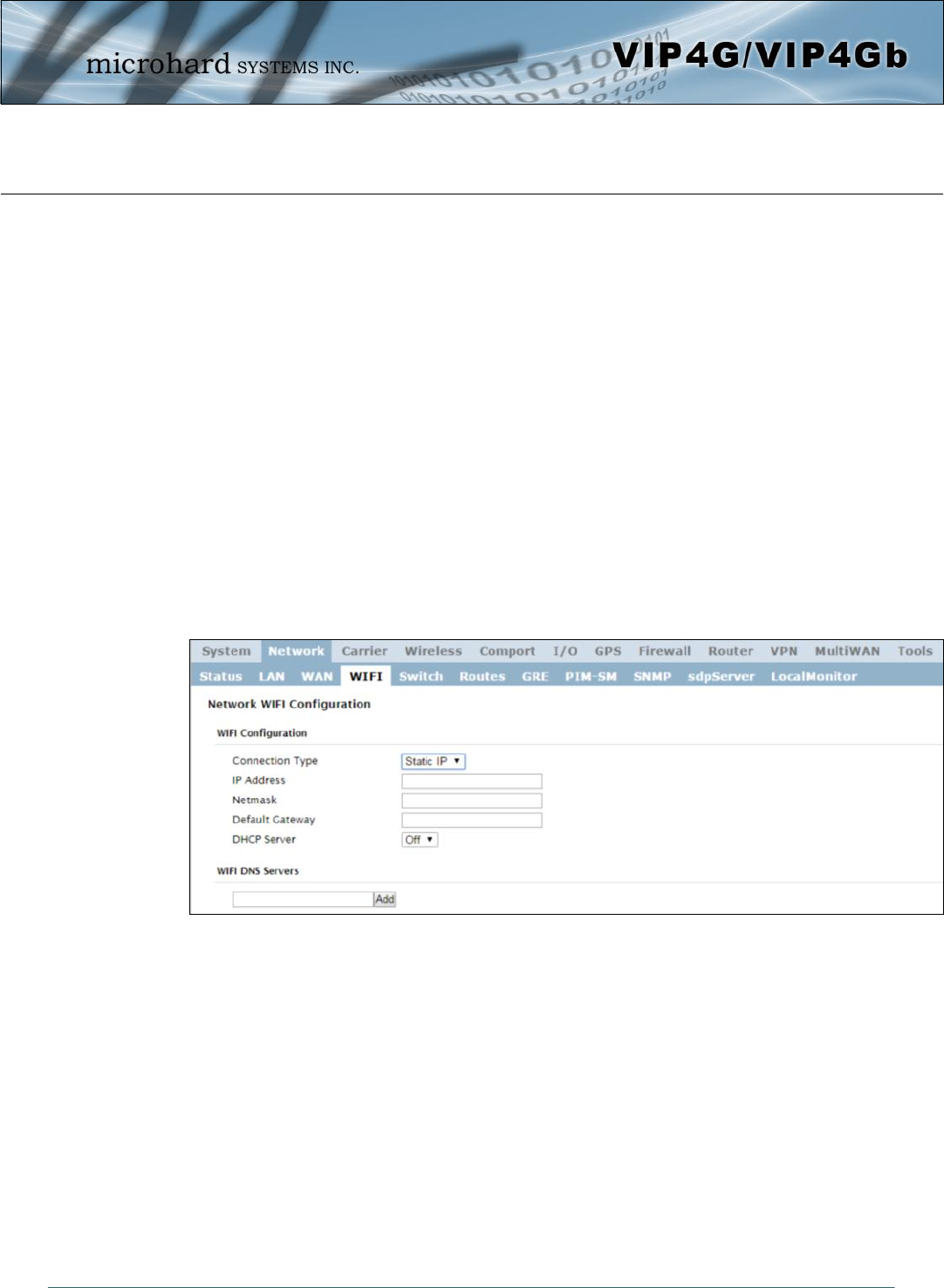
© Microhard Systems Inc. 49
4.0 Configuration
4.2.4 Network > WIFI
Network WIFI Configuration
The WIFI menu is used to define (if required) a virtual interface in which to bind a WIFI connection. This
connection can then be bound to the Wireless Radio in the Wireless > Radio1 menu. If this interface is not
bound to the Wireless interface it has no operation or purpose.
The WIFI interface can be used setup a separate WIFI connection for connected devices (separating them
from the devices connected to the LAN), this would be the same as adding another interface under the
LAN configuration. In this mode the VIP4G would be operating as a Access Point (AP) providing network
access to any connected devices. A separate DHCP server must be defined if it is required to provide
DHCP services to connecting devices.
In most cases the WIFI interface would be setup to allow the VIP4G to operate as a Client to another
Access Point (AP). Using this menu it can be decided to use DHCP to obtain an IP address and related
networking information from the connected Access Point, or it could be setup with a static IP address that
is part of the AP’s network.
When connected as a Client the VIP4G would be able to use the WIFI network for data rather that the
cellular connection. However unless NetMotion or a static default route was set to manage this
connection there would be no way to predict which interface is used for data.
Image 4-2-7: Network > WIFI
WIFI Configuration
The description of each of the parameters for setting up a WIFI interface is identical to those of adding/
editing a virtual LAN interface, which is discussed in the last section.
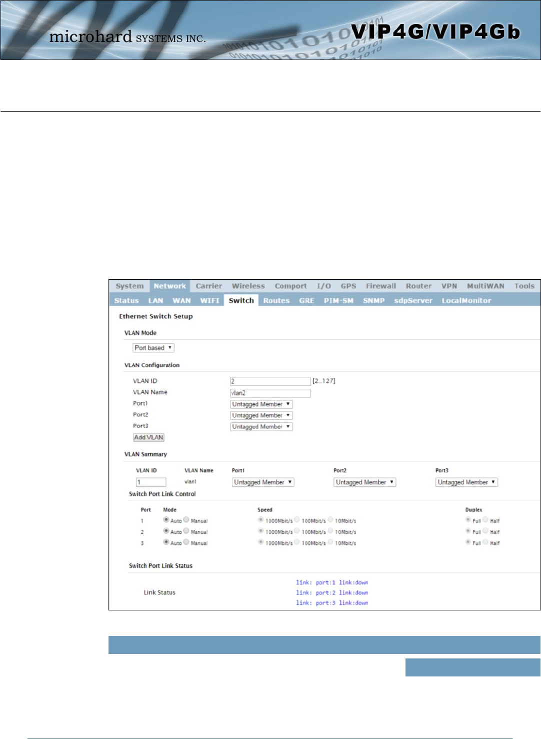
© Microhard Systems Inc. 50
4.0 Configuration
4.2.5 Network > Switch
The VIP4G has the capability to add multiple network interfaces. It may also be desirable to segment these
different subnets. The VIP4G features two different VLAN mode, Port Based, and 802.1Q VLAN.
In port based VLAN port membership is exclusive, a port can only belong to a single VLAN, and is
generally used to separate the different subnets. In a port based VLAN every port should be a Untagged
Member, not a Tagged Member.
802.1Q VLAN uses tagging to allow separation of network segments. Ports can belong to multiple VLANs.
A Trunk port can be configured to communicate with other VLAN switch by adding all configured VLANs to
a single port. The native VLAN1 is used by default, it is important that any connected VLAN switch use the
same Native VLAN.
Image 4-2-8: Network > Switch
By default the VIP4G is configured to Port Based VLAN with all ports
bridged. See above description for differences between Port Based
and Tagged VLANs.
VLAN Mode
Values (selection)
Port Based
802.1Q (Tagged)
© Microhard Systems Inc. 51
4.0 Configuration
By default the VIP4G is configured to Port Based VLAN with all ports
bridged. See above description for differences between Port Based
and Tagged VLANs.
VLAN Mode
Values (selection)
Port Based
802.1Q (Tagged)
If 802.1Q is selected for the VLAN mode, the Native VLAN can be
configured here. It is important for switch-to-switch connections to use
a consistent Native VLAN.
Native VLAN
Values
1
When adding a VLAN you must select a VLAN ID. Select between 2
and 127 for valid VLAN IDs.
VLAN ID
Values
2 (2-127)
VLAN names can be added to aid in VLAN identification (purpose, I,e
Engineering, Accounting, etc).
VLAN Name
Values
vlan2
Assign port to the current VLAN.
Exclude: Not part of the current VLAN
Tagged Member: In 802.1Q this assigns the current VLAN to the port,
Untagged Member: In port based VLAN this assigns a port to the
current VLAN. As mentioned previously, in port based VLAN, ports can
only belong to a single VLAN.
Port 1 - 3
Values (selection)
Exclude
Tagged Member
Untagged Member
Allows the user the ability to assign specific configured network
interfaces to a specific VLAN. (802.1Q)
Network
Values (selection)
None
LAN
(additional network interfaces)
If 802.1Q is selected for the VLAN mode, the Native VLAN can be
configured here. It is important for switch-to-switch connections to use
a consistent Native VLAN.
Native VLAN
Values
1
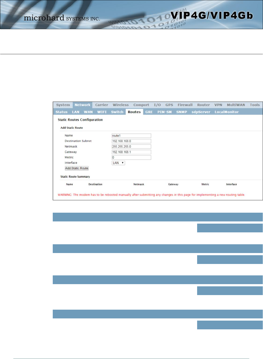
© Microhard Systems Inc. 52
4.0 Configuration
4.2.6 Network > Routes
Static Routes Configuration
It may be desirable to have devices on different subnets to be able to talk to one another. This can be
accomplished by specifying a static route, telling the VIP4G where to send data. The modem must be
restarted before new routes will take effect.
Image 4-2-9: Network > Routes
Routes can be names for easy reference, or to describe the route
being added.
Name
Values (characters)
(no default)
Enter the network IP address for the destination.
Destination
Values (IP Address)
(192.168.168.0)
Specify the Gateway used to reach the network specified above.
Gateway
Values (IP Address)
192.168.168.1
Enter the Netmask for the destination network.
Netmask
Values (IP Address)
255.255.255.0

© Microhard Systems Inc. 53
4.0 Configuration
In some cases there may be multiple routes to reach a destination.
The Metric can be set to give certain routes priority, the lower the
metric is, the better the route. The more hops it takes to get to a
destination, the higher the metric.
Metric
Values (Integer)
0
Define the exit interface. Is the destination a device on the LAN, or the
WAN?
Interface
Values (Selection)
LAN
WAN
4G
None
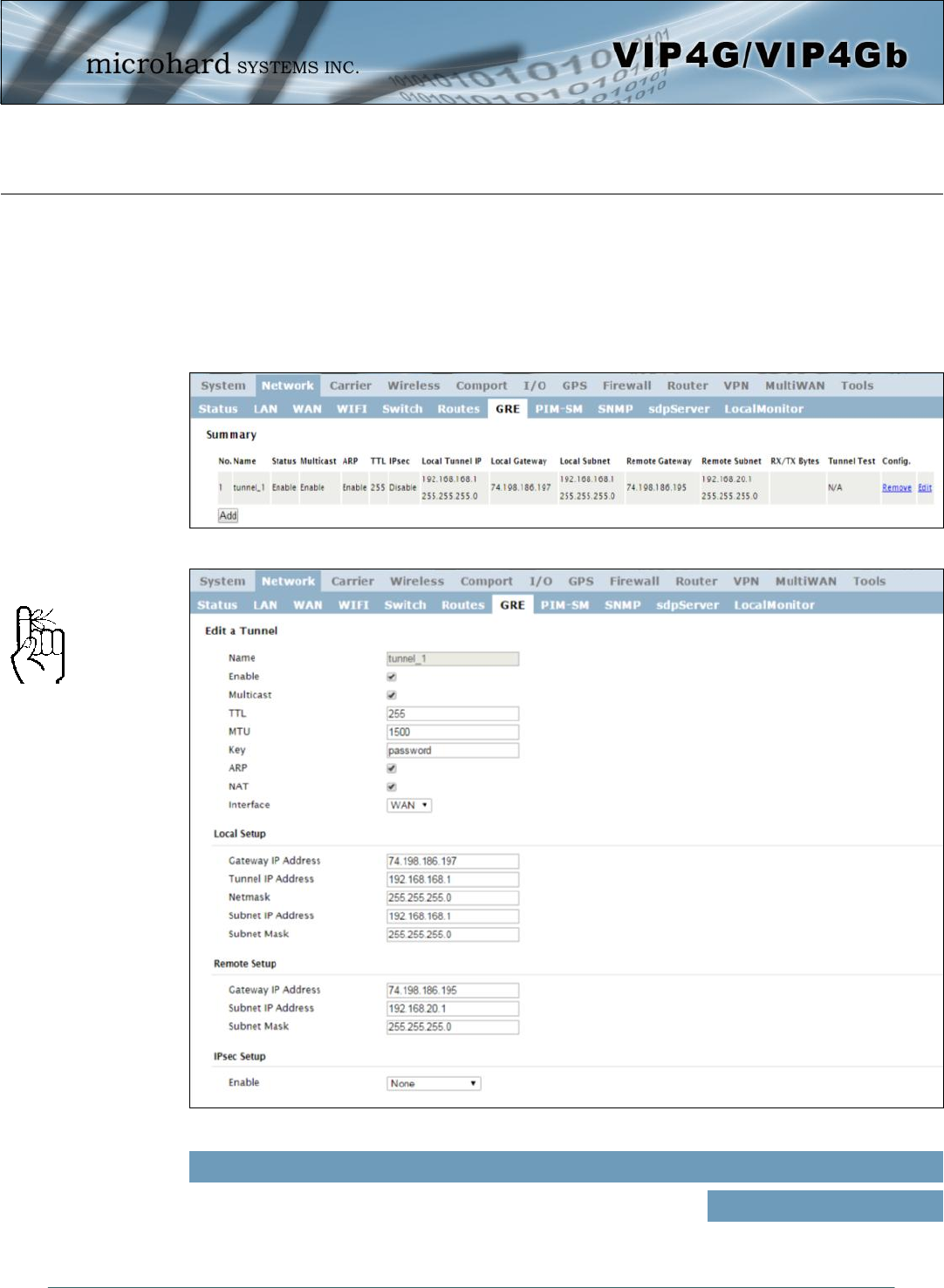
© Microhard Systems Inc. 54
4.0 Configuration
Image 4-2-10: Network > GRE Summary
4.2.7 Network > GRE
GRE Configuration
The VIP4G supports GRE (Generic Routing Encapsulation) Tunneling which can encapsulate a wide
variety of network layer protocols not supported by traditional VPN. This allows IP packets to travel from
one side of a GRE tunnel to the other without being parsed or treated like IP packets.
Each GRE tunnel must have a unique name. Up to 10 GRE tunnels
are supported by the VIP4G.
Name
Values (Chars(32))
gre
Image 4-2-11: Network > Edit/Add GRE Tunnel
For an example of how to set
up a GRE Tunnel, refer to the
Appendix: GRE Example.
© Microhard Systems Inc. 55
4.0 Configuration
Enable
Enable / Disable the GRE Tunnel. Values (selection)
Disable / Enable
Multicast
Enable / Disable Multicast support over the GRE tunnel. Values (selection)
Disable / Enable
ARP
Enable / Disable ARP (Address Resolution Protocol) support over the GRE
tunnel. Values (selection)
Disable / Enable
TTL
Set the TTL (Time-to-live) value for packets traveling through the GRE
tunnel. Values (value)
1 - 255
Gateway IP Address
This is the WAN IP Address of the VIP4G, this field should be populated
with the current WAN IP address. Values (IP Address)
(varies)
Tunnel IP Address
This is the IP Address of the local tunnel. Values (IP Address)
(varies)
Key
Enter a key is required, key must be the same for each end of the GRE
tunnel. Values (chars)
(none)
Netmask
Enter the subnet mask of the local tunnel IP address. Values (IP Address)
(varies)
Local Setup
The local setup refers to the local side of the GRE tunnel, as opposed to the remote end.
For an example of how to set
up a GRE Tunnel, refer to the
Appendix: GRE Example.
© Microhard Systems Inc. 56
4.0 Configuration
Subnet IP Address
The is the IP Address of the remote network, on the remote side of the
GRE Tunnel. Values (IP Address)
(varies)
Gateway IP Address
Enter the WAN IP Address of the VIP4G or other GRE supported device in
which a tunnel is to be created with at the remote end. Values (IP Address)
(varies)
Subnet Mask
The subnet mask for the local network/subnet. Values (IP Address)
(varies)
Subnet IP Address
Enter the subnet address for the local network. Values (IP Address)
(varies)
Remote Setup
The remote setup tells the VIP4G about the remote end, the IP address to create the tunnel to, and the
subnet that is accessible on the remote side of the tunnel.
Subnet Mask
The is the subnet mask for the remote network/subnet. Values (IP Address)
(varies)
IPsec Setup
Refer to the IPsec setup in the VPN Site to Site section of the manual for more information.
For an example of how to set
up a GRE Tunnel, refer to the
Appendix: GRE Example.
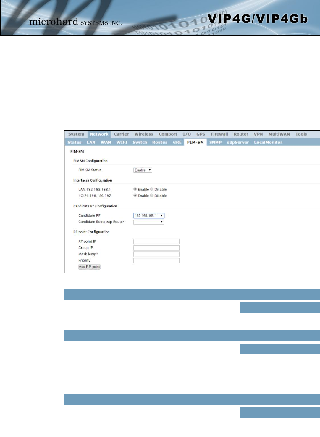
© Microhard Systems Inc. 57
4.0 Configuration
4.2.8 Network > PIM-SM
PIM-SM Configuration
The VIP4G can be set up with Protocol Independent Multicast - Sparse Mode (PIM-SM) which is a
multicast routing protocol developed by Cisco Systems. This menu allows the configuration of the VIP4G to
perform as a multicast router, which when enabled can transport multicast data streams to/from other
multicast routers or to/from source/clients.
Image 4-2-12: Network > PIM-SM Configuration
This is the main control to enable or disable the PIM-SM service on the
VIP4G. If disabled PIM-SM is not running and will not operate as a
Multicast Router.
PIM-SM Status
Values (selection)
Enable / Disable
Shows a list of available interfaces that can support multicast. Users
can select which interfaces are to use multicast.
Interfaces Configuration
Values (selection)
Enable / Disable
Candidate RP Configuration
This field is used to set up which port (IP address) is used as
Candidate Rendezvous Point (CRP). It specifies which interface on
the modem should be included in RP elections.
Candidate RP
Values (selection)
Varies based on configured
interfaces
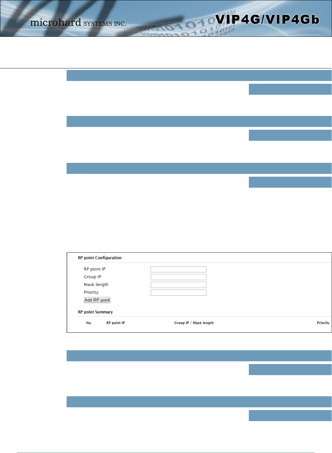
© Microhard Systems Inc. 58
4.0 Configuration
Set the time (seconds) in which to advertise this CRP (Candidate
Rendezvous Point).
time
Values (seconds)
(none)
The priority determines how important this CRP is compared to others.
The lower the value, the more important the CRP.
Priority
Values (integer)
(none)
This field is used to set up which port (IP address) is used as the
Candidate Bootstrap Router.
Candidate Bootstrap Router
Values (selection)
Varies based on configured
interfaces
Candidate RP Configuration
The RP Point Configuration is for static Rendezvous Point Configurations. The argument can be either a
unicast address or a multicast group, with optional group address, mask length, and priority arguments as
seen below.
Image 4-2-13: Network > PIM-SM Configuration
If the static RP is a unicast address, enter that address here.
RP Point IP
Values
(none)
Enter the optional multicast group IP here for the RP.
Group IP
Values
(none)
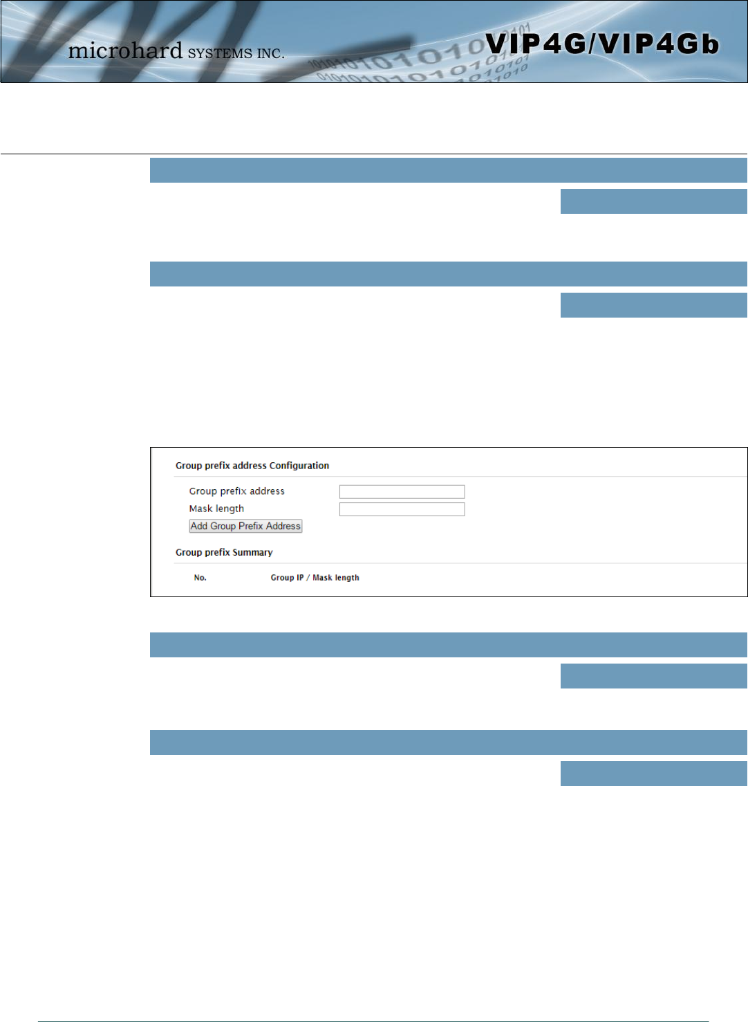
© Microhard Systems Inc. 59
4.0 Configuration
Enter the optional mask length here.
Mask Length
Values
(none)
A priority value can be set in the filed. The lower this value, the higher
the priority.
Priority
Values
(none)
Group Prefix Address Configuration
The group prefix statement outlines the set of multicast addresses that the CRP, if it wins an election, will
advertise to other routers.
Image 4-2-14: Network > PIM-SM Configuration
A specific multicast group or network range this router will handle.
Group Prefix Address
Values
(none)
The number of IP address segments taken up by the netmask.
Remember that a multicast address is a Class D and has a netmask of
240.0.0.0, which means its length is 4.
Mask Length
Values
(none)
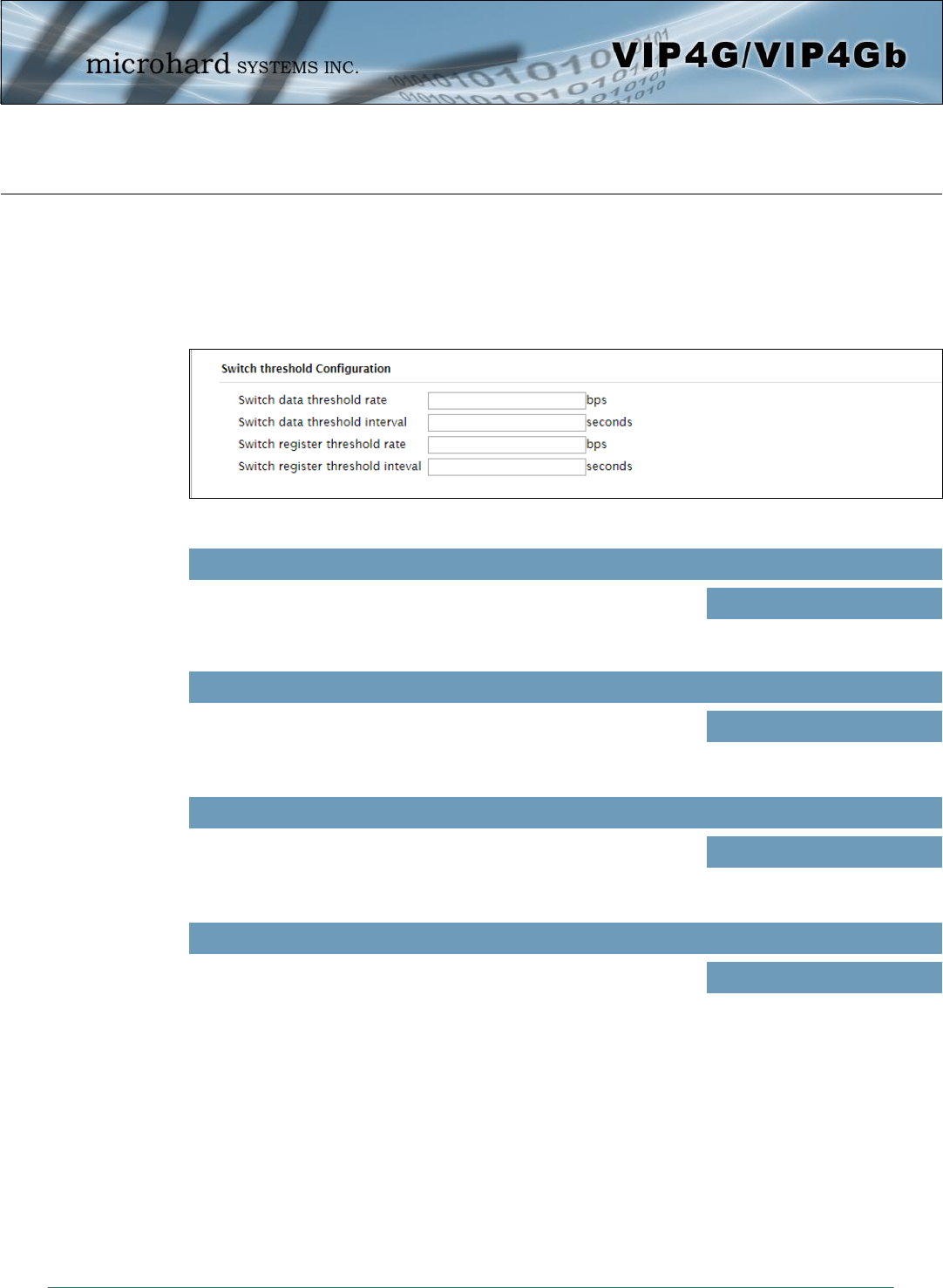
© Microhard Systems Inc. 60
4.0 Configuration
Switch Threshold Configuration
The Switch Data Threshold setting defines the threshold at which transmission rates trigger the
changeover from the shared tree to the RP tree; Switch Register Threshold does the opposite in the same
format. Regardless of which of these you choose, the rate option is for transmission rate in bits per second,
interval is the sample rate in seconds -- with a recommended minimum of five seconds. It is recommended
to have the same interval if both settings are used.
Image 4-2-15: Network > PIM-SM Configuration
The Switch Data Threshold setting defines the threshold at which
transmission rates trigger the changeover from the shared tree to the
RP tree.
Switch Data Threshold Rate
Values (bps)
(none)
Sample rate in seconds (recommended minimum of 5 seconds)
Switch Data Threshold Interval
Values (seconds)
(none)
Switch Register Threshold does the opposite of the Switch Data
Threshold Rate in the same format.
Switch Register Threshold Rate
Values (bps)
(none)
Sample rate in seconds (recommended minimum of 5 seconds)
Switch Register Threshold Interval
Values (seconds)
(none)
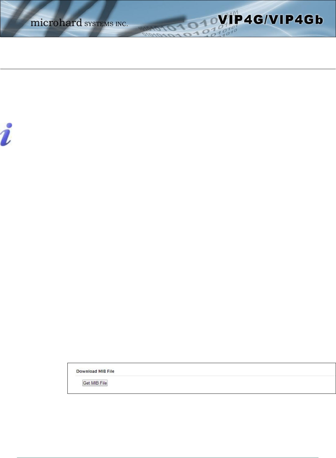
© Microhard Systems Inc. 61
4.0 Configuration
4.2.10 Network > SNMP
The VIP4G may be configured to operate as a Simple Network Management Protocol (SNMP) agent.
Network management is most important in larger networks, so as to be able to manage resources and
measure performance. SNMP may be used in several ways:
configure remote devices
monitor network performance
detect faults
audit network usage
detect authentication failures
A SNMP management system (a PC running SNMP management software) is required for this service to
operate. This system must have full access to the VIP4G. Communications is in the form of queries
(information requested by the management system) or traps (information initiated at, and provided by, the
SNMP agent in response to predefined events).
Objects specific to the VIP4G are hosted under private enterprise number 21703.
An object is a variable in the device and is defined by a Management Information Database (MIB). Both
the management system and the device have a copy of the MIB. The MIB in the management system
provides for identification and processing of the information sent by a device (either responses to queries
or device-sourced traps). The MIB in the device relates subroutine addresses to objects in order to read
data from, or write data to, variables in the device.
An SNMPv1 agent accepts commands to retrieve an object, retrieve the next object, set and object to a
specified value, send a value in response to a received command, and send a value in response to an
event (trap).
SNMPv2c adds to the above the ability to retrieve a large number of objects in response to a single
request.
SNMPv3 adds strong security features including encryption; a shared password key is utilized. Secure
device monitoring over the Internet is possible. In addition to the commands noted as supported above,
there is a command to synchronize with a remote management station.
The pages that follow describe the different fields required to set up SNMP on the VIP4G. MIBS may be
requested from Microhard Systems Inc.
The MIB file can be downloaded directly from the unit using the ‘Get MIB File’ button on the Network >
SNMP menu.
SNMP: Simple Network
Management Protocol
provides a method of
managing network
devices from a single PC
running network
management software.
Managed networked
devices are referred to as
SNMP agents.
Image 4-2-16: Network > MIB Download
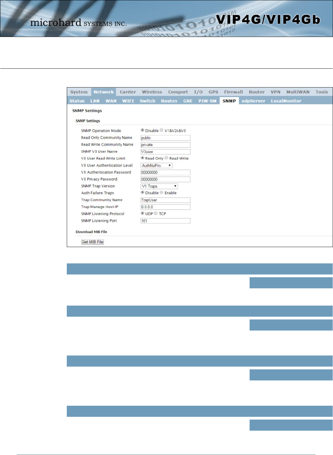
© Microhard Systems Inc. 62
4.0 Configuration
Image 4-2-17: Network > SNMP
If disabled, an SNMP service is not provided from the device.
Enabled, the device - now an SNMP agent - can support SNMPv1, v2,
& v3.
SNMP Operation Mode
Values (selection)
Disable / V1&V2c&V3
SNMP Settings
Effectively a plain-text password mechanism used to weakly
authenticate SNMP queries. Being part of the community allows the
SNMP agent to process SNMPv1 and SNMPv2c requests. This
community name has only READ priority.
Read Only Community Name
Values (string)
public
Also a plain-text password mechanism used to weakly authenticate
SNMP queries. Being part of the community allows the SNMP agent to
process SNMPv1 and SNMPv2c requests. This community name has
only READ/WRITE priority.
Read Only Community Name
Values (string)
private
Defines the user name for SNMPv3.
SNMP V3 User Name
Values (string)
V3user
© Microhard Systems Inc. 63
4.0 Configuration
Defines accessibility of SNMPv3; If Read Only is selected, the
SNMPv3 user may only read information; if Read Write is selected, the
SNMPv3 user may read and write (set) variables.
V3 User Read Write Limit
Values (selection)
Read Only / Read Write
Defines SNMPv3 user’s authentication level:
NoAuthNoPriv: No authentication, no encryption.
AuthNoPriv: Authentication, no encryption.
AuthPriv: Authentication, encryption. (Not supported)
V3 User Authentication Level
Values (selection)
NoAuthNoPriv
AuthNoPriv
AuthPriv
SNMPv3 user’s authentication password. Only valid when V3 User
Authentication Level set to AuthNoPriv or AuthPriv.
V3 User Authentication Password
Values (string)
00000000
SNMPv3 user’s encryption password. Only valid when V3 User
Authentication Level set to AuthPriv (see above).
V3 User Privacy Password
Values (string)
00000000
Select which version of trap will be sent should a failure or alarm
condition occur.
SNMP Trap Version
Values (string)
V1 Traps V2 Traps
V3 Traps V1&V2 Traps
V1&V2&V3 Traps
If enabled, an authentication failure trap will be generated upon
authentication failure.
Auth Failure Traps
Values (selection)
Disable / Enable
The community name which may receive traps.
Trap Community Name
Values (string)
TrapUser
Defines a host IP address where traps will be sent to (e.g. SNMP
management system PC IP address).
Trap Manage Host IP
Values (IP Address)
0.0.0.0
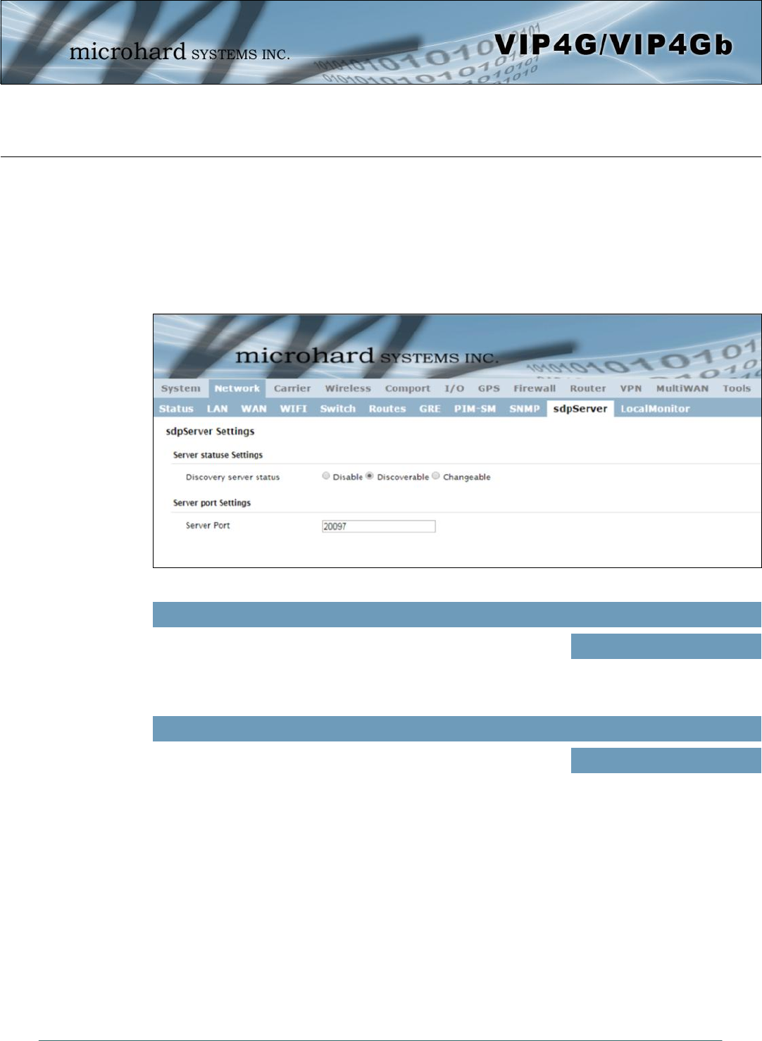
© Microhard Systems Inc. 64
4.0 Configuration
Image 4-2-18: Network > sdpServer Settings
Use this option to disable or enable the discovery service.
Discovery Service Status
Values (selection)
Disable / Discoverable /
Changable
4.2.10 Network > sdpServer
sdpServer Settings
Microhard Radio employ a discovery service that can be used to detect other Microhard Radio’s on a
network. This can be done using a stand alone utility from Microhard System’s called ‘IP Discovery’ or from
the Tools > Discovery menu. The discovery service will report the MAC Address, IP Address, Description,
Product Name, Firmware Version, Operating Mode, and the SSID.
Specify the port running the discovery service on the VIP4G unit.
Server Port Settings
Values (Port #)
20097
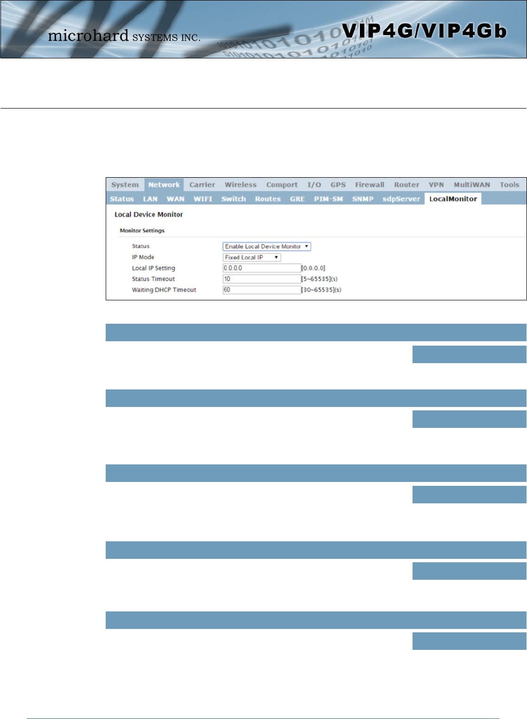
© Microhard Systems Inc. 65
4.0 Configuration
Image 4-2-19: Network Configuration , Local Monitor
4.2.11 Network > Local Monitor
The Local Device Monitor allows the VIP4G to monitor a local device connected locally to the Ethernet port
or to the locally attached network. If the VIP4G cannot detect the specified IP or a DHCP assigned IP, the
unit will restart the DHCP service, and eventually restart the modem to attempt to recover the connection.
IP Mode
Select the IP mode. By selecting a fixed IP address the service will monitor
the connection to that specific IP. If auto detect is selected, the VIP4G will
detect and monitor DHCP assigned IP address.
Status
Enable or disable the local device monitoring service.
Disable / Enable
Values (selection)
Fixed local IP
Auto Detected IP
Values (selection)
Local IP Setting
This field is only shown if Fixed Local IP is selected for the IP Mode. Enter
the static IP to be monitored in this field. 0.0.0.0
Values (IP)
Status Timeout
The status timeout is the maximum time the VIP4G will wait to detect the
monitored device. At this time the VIP4G will restart the DHCP service. (5-
65535 seconds) 10
Values (seconds)
Waiting DHCP Timeout
This field defines the amount of time the VIP4G will wait to detect the
monitored device before it will reboot the modem. (30-65535 seconds)
60
Values (seconds)
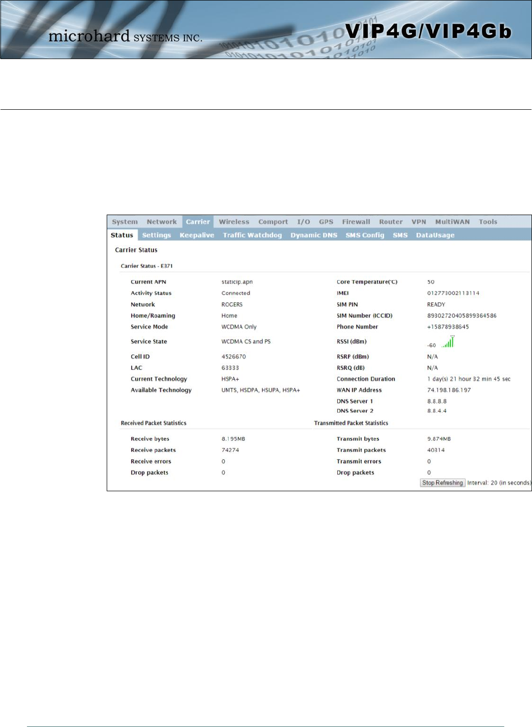
© Microhard Systems Inc. 66
4.0 Configuration
Image 4-3-1: Carrier > Status
4.3 Carrier
4.3.1 Carrier > Status
The Carrier Status window provides complete overview information related to the Cellular Carrier portion of
the VIP4G. A variety of information can be found here, such as Activity Status, Network (Name of Wireless
Carrier connected) , Data Service Type WCDMA/HSPA/HSPA+/LTE etc), Frequency band, Phone Number
etc.
Not all statistics parameters displayed are applicable.
The Received and Transmitted bytes and packets indicate the respective amount of data which has been
moved through the radio.
The Error counts reflect those having occurred on the wireless link.
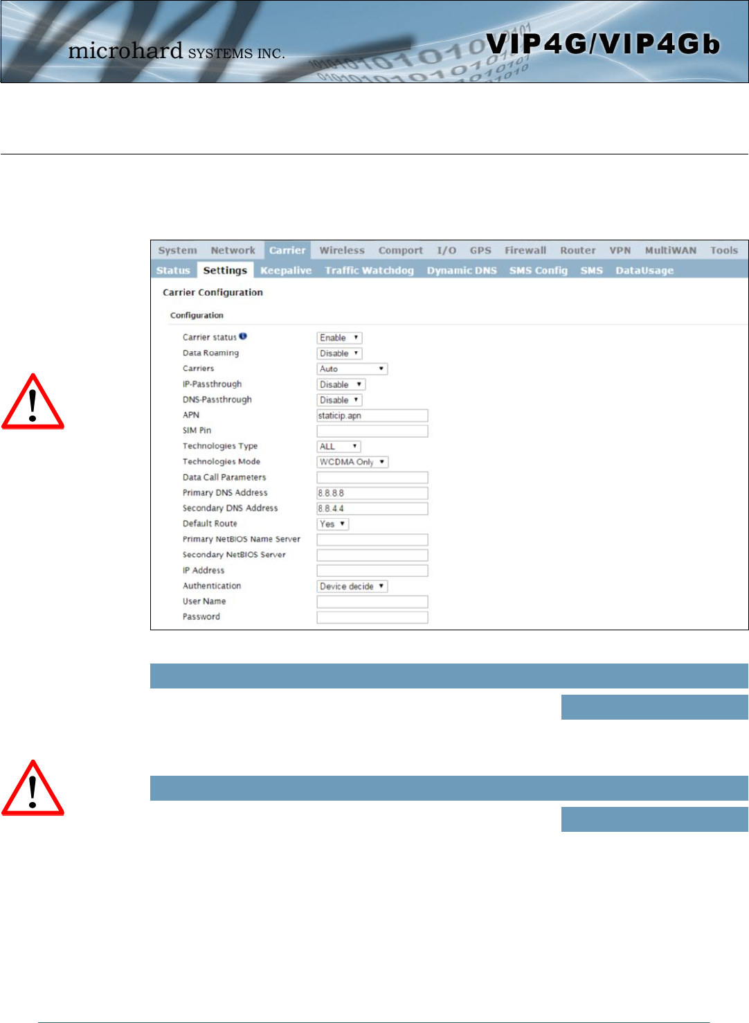
© Microhard Systems Inc. 67
4.0 Configuration
Image 4-3-2: Carrier > Settings
4.3.2 Carrier > Settings
The parameters within the Carrier Configuration menu must be input properly; they are the most basic
requirement required by your cellular provider for network connectivity.
Carrier Status is used to Enable or Disable the connection to the
Cellular Carrier. By default this option is enabled. If disabled the
cellular module is disabled and the modem will not even attempt to
connect to the cellular carrier.
Carrier Status
Values (Selection)
Enable
Disable
Enable or disable Data Roaming. If enabled the modem will be allowed
to roam on another carriers’ network if their home carrier is not
available. In most cases the data roaming usage data charges are
much higher than home service areas. Roaming is Disabled by default.
Data Roaming
Values (Selection)
Enable
Disable
Enabling Data Roaming
may result in increased
data charges from the
Carrier. In some cases this
could be an excessive,
and unexpected amount. It
is important to understand
the data plan with the
Cellular Carrier.
For best practices and to
control data usage it is
critical that the firewall be
configured properly.
It is recommended to block
all incoming 4G/Cellular
traffic and create rules to
open specific ports and/or
use ACL lists to limit
incoming connections.

© Microhard Systems Inc. 68
4.0 Configuration
IP pass-through allows the 4G WAN IP address to be assigned to the device
connected to the physical LAN or WAN Port (DHCP or Static). In this mode the
VIP4G is for the most part transparent and forwards all traffic to the device
connected to the specified port except that listed below:
The WebUI port (Default Port:TCP 80), this port is retained for remote
management of the VIP4G. This port can be changed to a different port
under the System > Settings Menu.
The SNMP Listening Port (Default Port: UDP 161).
Local WebUI of the VIP4G is retained by using the first 3 octets of the Wan IP
and changing the last octet to 1.
IP-Passthrough
Values (Selection)
Disable
Ethernet
WAN Port
In some cases, a user may want to lock onto certain carrier to avoid data
roaming. There were four options presented to a user to choose from, Auto,
SIM based, Scan & Select and Fixed.
Auto will allow the VIP4G to pick the carrier automatically. Data roaming is
permitted.
SIM based will only allow the VIP4G to connect to the network indicated by
the SIM card used in the unit.
Manual will scan for available carriers and allow a user to select from the
available carriers. It takes 2 to 3 minutes to complete a scan.
Fixed allows a user to enter the carrier code (numerical) directly and then the
VIP4G will only connect to that carrier.
Carriers
Values (Selection)
Auto
Based on SIM
Manual
Fixed
This field is only visible once IP Passthrough has been selected
above. This gives the user the option to manually configure the IP-
Passthrough feature of the modem. (It is recommended to only use
this option if you are an advanced user and the automatic settings do
not work for your application or carrier)
IP-Passthrough Mode
Values (selection)
Auto / Manual
This field is used to specify the Gateway to be used for IP Passthrough
if set to manual mode. As mentioned above it is recommended to use
the Auto mode for IP-Passthrough.
IP-Passthrough Gateway
Values
(no default)
This field is used to specify the Netmask to be used for IP Passthrough
if set to manual mode. As mentioned above it is recommended to use
the Auto mode for IP-Passthrough.
IP-Passthrough Netmask
Values
(no default)
This is a read only field that displays the current IP address assigned by
the cellular carrier that will be assigned (DHCP) or needs to be
configured (Static) on the attached device.
IP-Passthrough Local IP
Values (selection)
(current carrier IP to be
assigned to attached
device).

© Microhard Systems Inc. 69
4.0 Configuration
If let blank the VIP4G with use the DNS server as specified
automatically by the service provider.
Primary DNS Address
Values (IP Address)
(none)
If let blank the VIP4G with use the DNS server as specified
automatically by the service provider.
Secondary DNS Address
Values (IP Address)
(none)
The Technologies Mode option allows a user the ability to specify what
type of Cellular networks to connect to.
Technologies Mode
Values (Selection)
AUTO / LTE Only / WCDMA
Only / GSM Only
Sets the modems connect string if required by the carrier. Not usually
required in North America.
Data Call Parameters
Values (string)
(none)
Set to ALL by default, the Technologies field allows the selection of
3GPP technologies (LTE), and or 3GPP2 technology (CDMA).
Technologies Type
Values (Selection)
ALL / 3GPP / 3GPP2
The SIM Pin is required for some international carriers. If supplied and
required by the cellular carrier, enter the SIM Pin here.
SIM Pin
Values (characters)
(none)
The APN is required by every Carrier in order to connect to their
networks. The APN defines the type of network the VIP4G is
connected to and the service type. Most Carriers have more than one
APN, usually many, dependant on the types of service offered.
APN (Access Point Name)
Values (characters)
auto
When enabled DNS-Passthrough will pass on the WAN assigned DNS
information to the end device.
DNS-Passthrough
Values (Selection)
Enable / Disable
Auto APN (default) may allow the unit to quickly connect to a carrier, by cycling through a predetermined
list of common APN’s. Auto APN will not work for private APN’s or for all carriers.
© Microhard Systems Inc. 70
4.0 Configuration
A User Name may be required for authentication to a remote peer.
Although usually not required for dynamically assigned IP addresses
from the wireless carrier, but required in most cases for static IP
addresses. Varies by carrier.
User Name
Values (characters)
Carrier/peer dependant
Enter the password for the user name above. May not be required by
some carriers, or APN’s
Password
Values (characters)
Carrier/peer dependant
Sets the authentication type required to negotiate with peer.
PAP - Password Authentication Protocol.
CHAP - Challenge Handshake Authentication Protocol.
Authentication
Values (Selection)
Device decide (AUTO)
PAP
CHAP
In some cases the Static IP address must be entered in this field if
assigned by a wireless carrier. In most cases the IP will be read from
the SIM card and this field should be left at the default value.
IP Address
Values (IP Address)
(none)
Enter the Primary NetBIOS Name Server if required by the carrier.
Primary NetBIOS Name Server
Values (IP Address)
(none)
Enter the Secondary NetBIOS Name Server if required by the carrier.
Secondary NetBIOS Name Server
Values (IP Address)
(none)
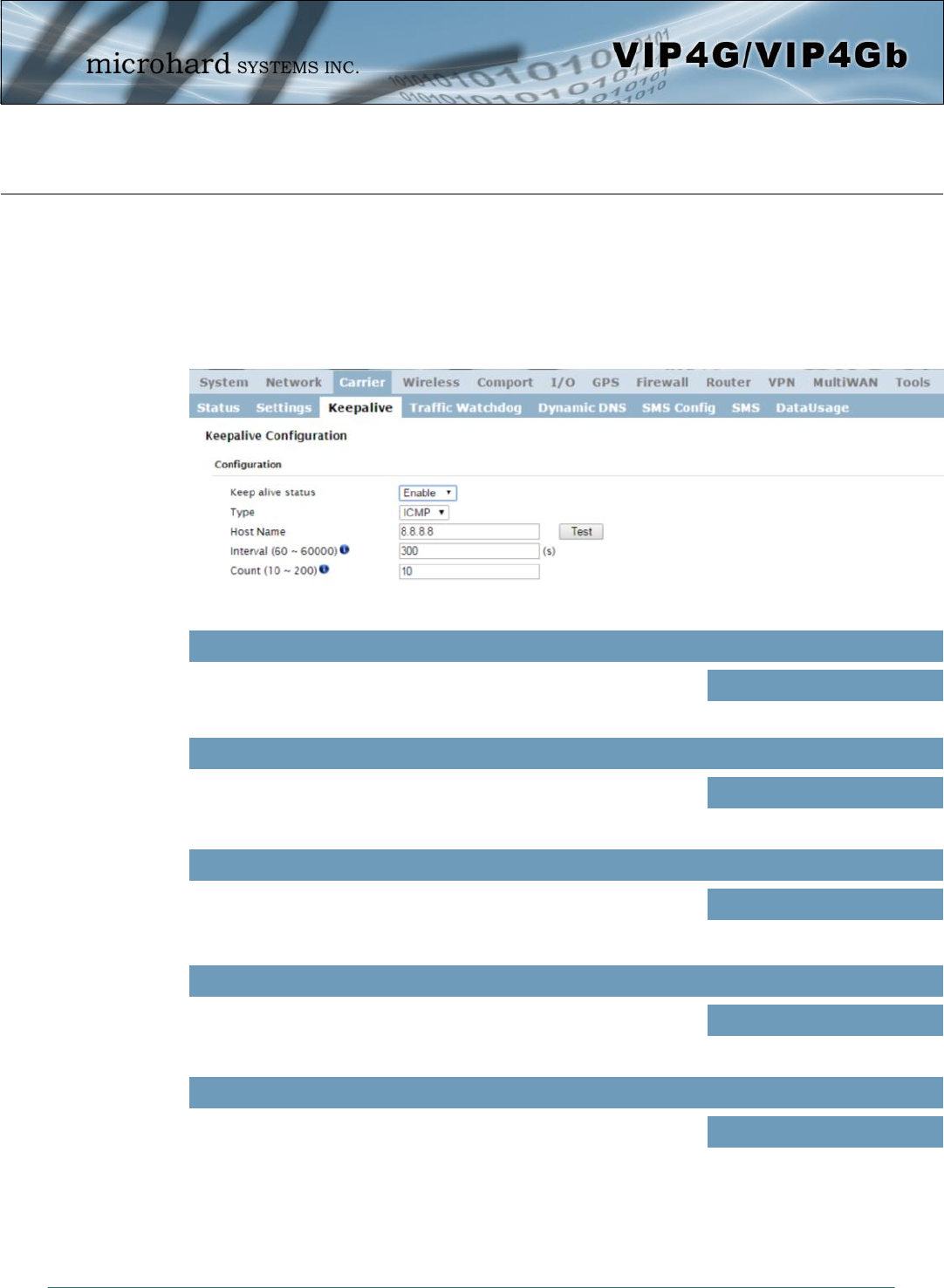
© Microhard Systems Inc. 71
4.0 Configuration
Image 4-3-3: Carrier > Keepalive
4.3.3 Carrier > Keepalive
The Keep alive tab allows for the configuration of the keep alive features of the VIP4G. The VIP4G can
either do a ICMP or HTTP keep alive by attempting to reach a specified address at a regular interval. If the
VIP4G cannot reach the intended destination, it will reset the unit in an attempt to obtain a new connection
to the carrier. The Keepalive ensures that there is internet/network connectivity to the address specified at
all times. If the VIP4G does not have a SIM card installed, is not connected to the Carrier, or is on a
private APN, the default keepalive may not work and the unit will reboot at the interval configured.
Enable or Disable the keep alive functions in the VIP4G.
Keep Alive Status
Values (Selection)
Enable / Disable
Select the type of keep alive used. ICMP uses a “ping” to reach a
select destination.
Type
Values (Selection)
ICMP / HTTP
Specify a IP Address or Domain that is used to test the VIP4G
connection. The ‘Test’ button can be used to verify that the specified
host/IP is reachable and a candidate for the keepalive feature.
Host Name
Values (IP or Domain)
8.8.8.8
The Interval value determines the frequency, or how often, the VIP4G
will send out PING messages to the Host.
Interval
Values (seconds)
300
The Count field is the maximum number of PING errors such as “Host
unreachable” the VIP4G will attempt before the unit will reboot itself to
attempt to correct connection issues. If set to zero (0), the unit will
never reboot itself.
Count
Values (number)
10
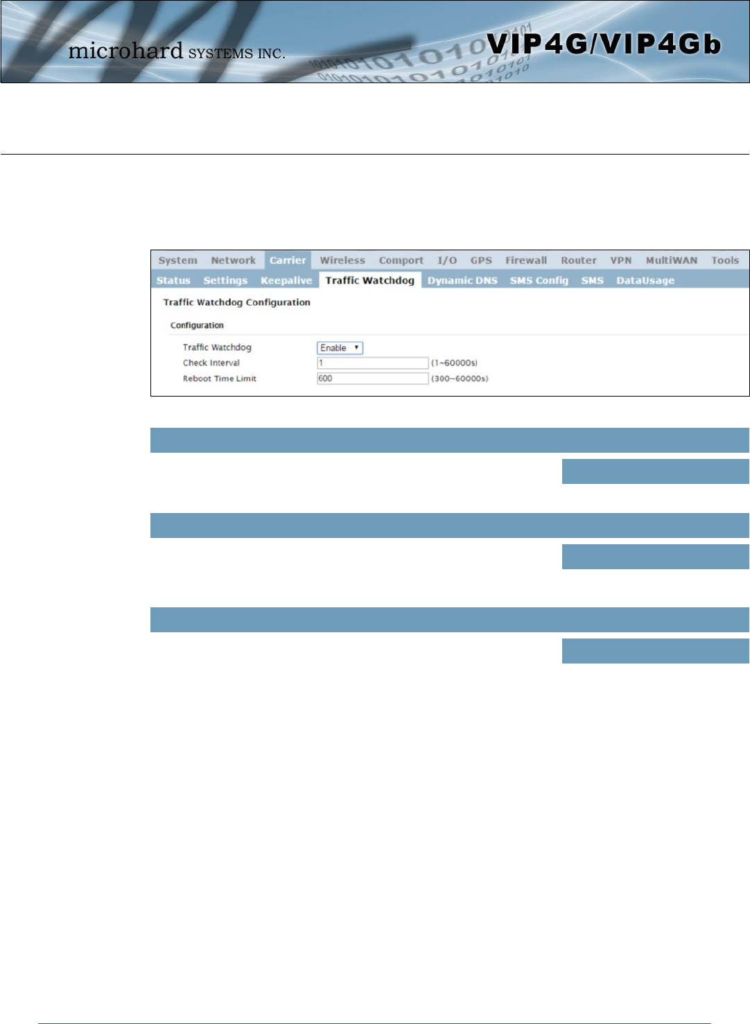
© Microhard Systems Inc. 72
4.0 Configuration
Image 4-3-4: Carrier > Traffic Watchdog
4.3.4 Carrier > Traffic Watchdog
The Wireless Traffic Watchdog will detect if there has been no wireless traffic, or communication with the
Cellular carrier for a configurable amount of time. Once that time has elapsed, the unit will reset, and
attempt to re-establish communication with the cellular carrier.
Enable or Disable the Traffic Watchdog.
Traffic Watchdog
Values (Selection)
Enable / Disable
The Check Interval tells the VIP4G how often (in seconds) to check for
wireless traffic to the cellular carrier. (1-60000 seconds)
Check Interval
Values (seconds)
1
The Reboot Timer will reset the unit if there has been no Cellular RF
activity in the configured time. (300 –60000 seconds)
Reboot Time Limit
Values (seconds)
600
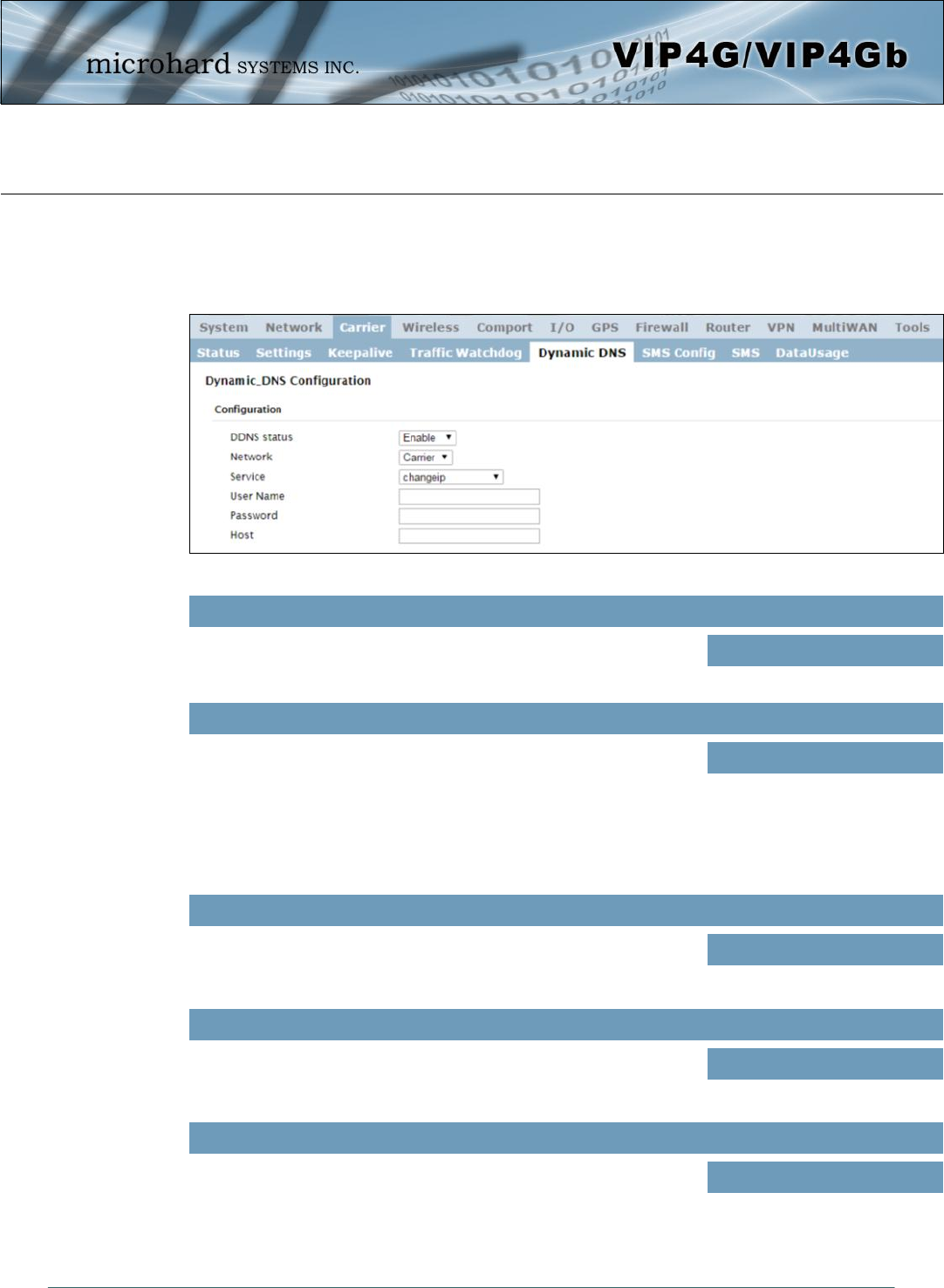
© Microhard Systems Inc. 73
4.0 Configuration
Image 4-3-5: Carrier > Traffic Watchdog
4.3.5 Carrier > Dynamic DNS
Unless a carrier issues a Static IP address, it may be desirable to use a dynamic DNS service to track
dynamic IP changes and automatically update DNS services. This allows the use of a constant resolvable
host name for the VIP4G.
This selection allows the use of a Dynamic Domain Name Server
(DDNS), for the VIP4G.
DDNS Status
Values (Selection)
Enable / Disable
This is a list of supported Dynamic DNS service providers. Free and
premium services are offered, contact the specific providers for more
information.
Service
Values (selection)
changeip
dyndns
eurodyndns
hn
noip
Enter a valid user name for the DDNS service selected above.
User Name
Values (characters)
(none)
ods
ovh
regfish
tzo
zoneedit
Enter a valid password for the user name of the DDNS service
selected above.
Password
Values (characters)
(none)
This is the host or domain name for the VIP4G as assigned by the
DDNS provider.
Host
Values (domain name)
(none)
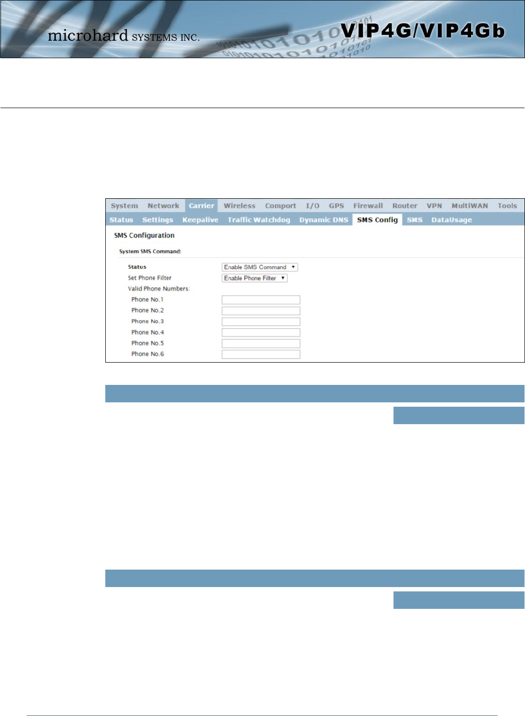
© Microhard Systems Inc. 74
4.0 Configuration
Image 4-3-6: SMS > SMS Configuration
This option allows a user to enable or disable to use of the following
SMS commands to reboot or trigger events in the VIP4G:
Status
Values (Selection)
Enable / Disable
If enabled, the VIP4G will only accept and execute commands
originating from the phone numbers in the Phone Filter List. Up to 6
numbers can be added.
Set Phone Filter
Values (Selection)
Enable / Disable
MSC#REBOOT Reboot system
MSC#NMS Send NMS UDP Report
MSC#WEB Send web client inquiry
MSC#MIOP1 open I/O ouput1
MSC#MIOP2 open I/O ouput2
MSC#MIOP3 open I/O ouput3
MSC#MIOP4 open I/O ouput4
MSC#MIOC1 close I/O ouput1
MSC#MIOC2 close I/O ouput2
MSC#MIOC3 close I/O ouput3
MSC#MIOC4 close I/O ouput4
4.3.6 Carrier > SMS Config
SMS messages can be used to remotely reboot or trigger events in the VIP4G. SMS alerts can be set up to
get SMS messages based on system events such as Roaming status, RSSI, Ethernet Link Status or IO
Status.
System SMS Command
MSC#EURD0 trigger event report0
MSC#EURD1 trigger event report1
MSC#EURD2 trigger event report2
MSC#EURD3 trigger event report3
MSC#GPSR0 trigger gps report0
MSC#GPSR1 trigger gps report1
MSC#GPSR2 trigger gps report2
MSC#GPSR3 trigger gps report3
SMS Commands are case sensitive.
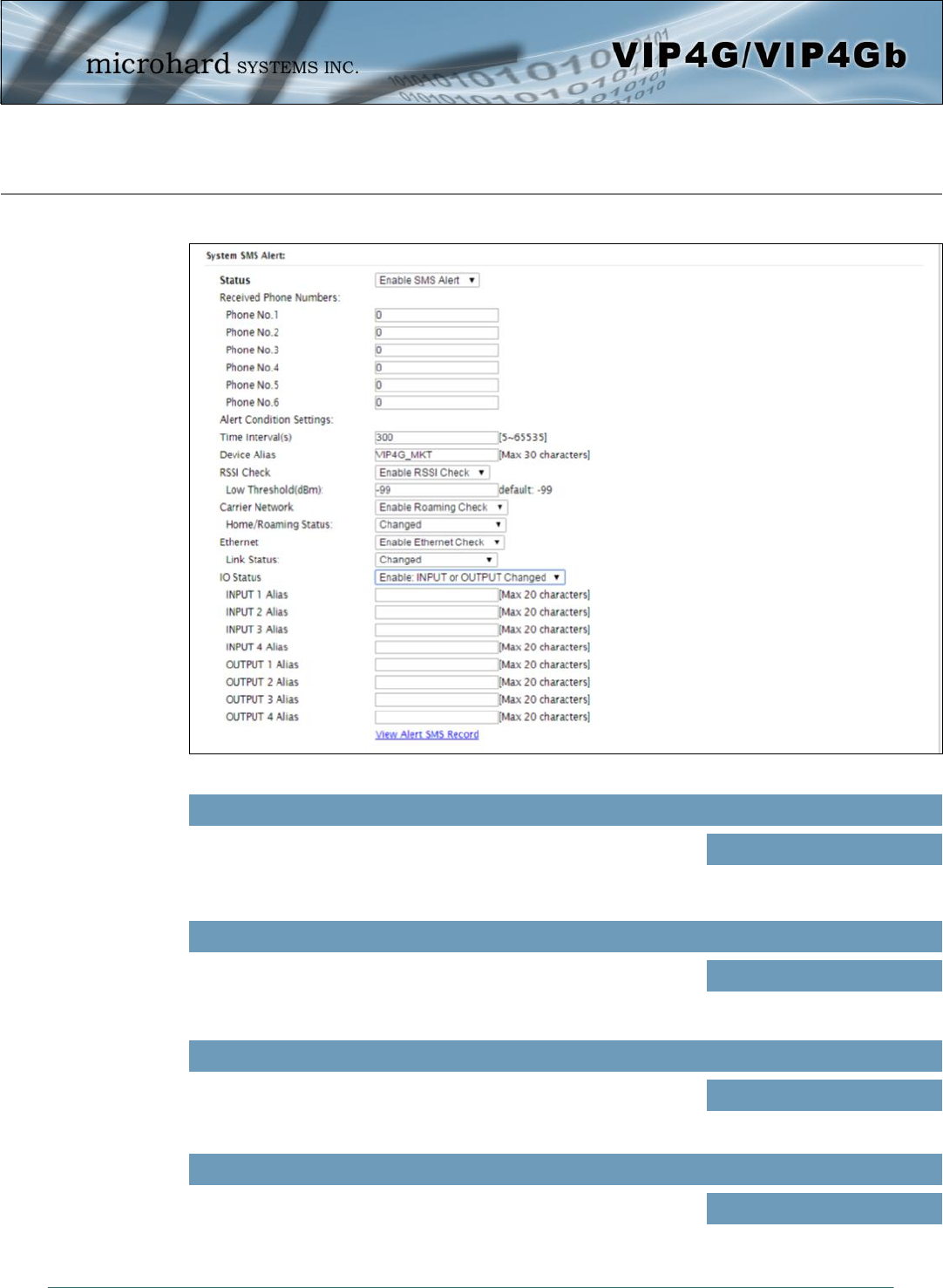
© Microhard Systems Inc. 75
4.0 Configuration
Image 4-3-7: SMS > SMS Alerts
System SMS Alerts
Enable SMS Alerts. IF enabled SMS alerts will be send when
conditions are met as configured to the phone numbers listed.
Status
Values (Selection)
Enable / Disable
SMS Alerts can be sent to up to 6 different phone numbers that are
listed here.
Received Phone Numbers
Values (Selection)
(no default)
SMS alerts, when active, will be sent out at the frequency defined
here.
Time Interval(s)
Values (Seconds)
300
The Device Alias allows you to add a useful, recognizable name or
other text characters with each SMS notifcation
Device Alias
Values (chars)
(varies)

© Microhard Systems Inc. 76
4.0 Configuration
The VIP4G can send alerts based on the roaming status. Data rates
during roaming can be expensive and it is important to know when a
device has started roaming.
Home / Roaming Status
Values (Selection)
In Roaming
Changed or In Roaming
Changed to Roaming
The status of the Ethernet Link of the LAN (RJ45) can be used to send
SMS Alerts. The link status may indicate an issue with the connected
device.
Ethernet Link Status
Values (Selection)
Changed
In no-link
Changed or in no-link
Changed to no-link
SMS Alerts can be sent based on the state changes of the Digital I/O
lines.
Input/Out Alias: Allows 20 characters to be added to the SMS
message to help identify the input or output that has triggered the alert.
I/O Status
Values (Selection)
Disable IO Check
Enable: INPUT Changed
Enable: Output Changed
Enable: INPUT or OUTPUT
Changed.
Set the threshold for RSSI alerts.
RSSI Check
Values (dBm)
-99
Enable or disable SMS Alerts for Roaming Status.
Carrier Network
Values (Selection)
Disable Roaming Check
Enable Roaming Check
Enable or disable SMS Alerts for the Ethernet Link status of the LAN
RJ45 port.
Ethernet
Values (Selection)
Disable Ethernet check
Enable Ethernet check
Enable or disable the RSSI alerts. If enable, enter the low RSSI
threshold.
RSSI Check
Values (Selection)
Disable RSSI check
Enable RSSI check
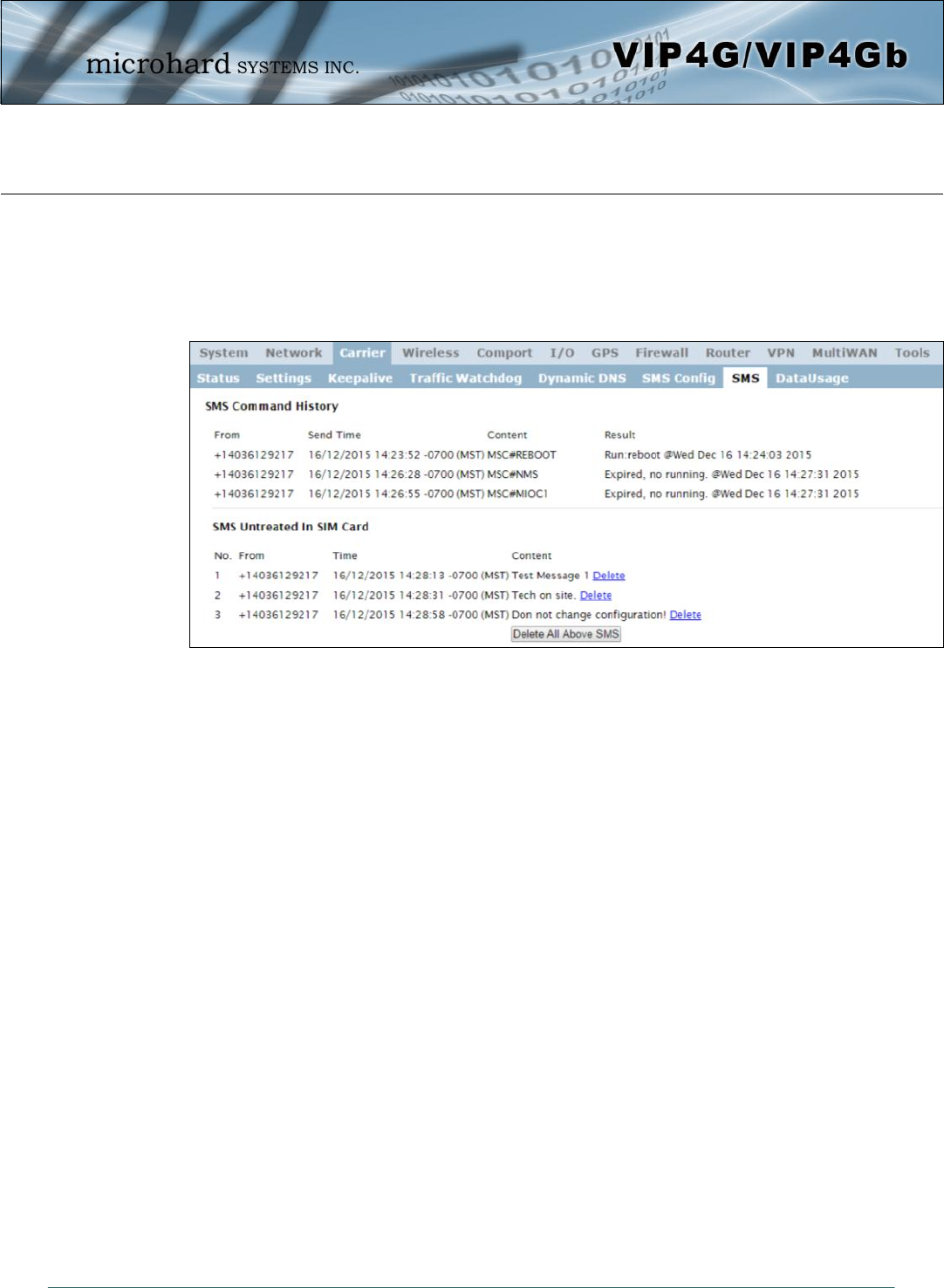
© Microhard Systems Inc. 77
4.0 Configuration
Image 4-3-8: SMS > SMS Command History
4.3.7 Carrier > SMS
SMS Command History
The SMS menu allows a user to view the SMS Command History and view the SMS messages on the SIM
Card.
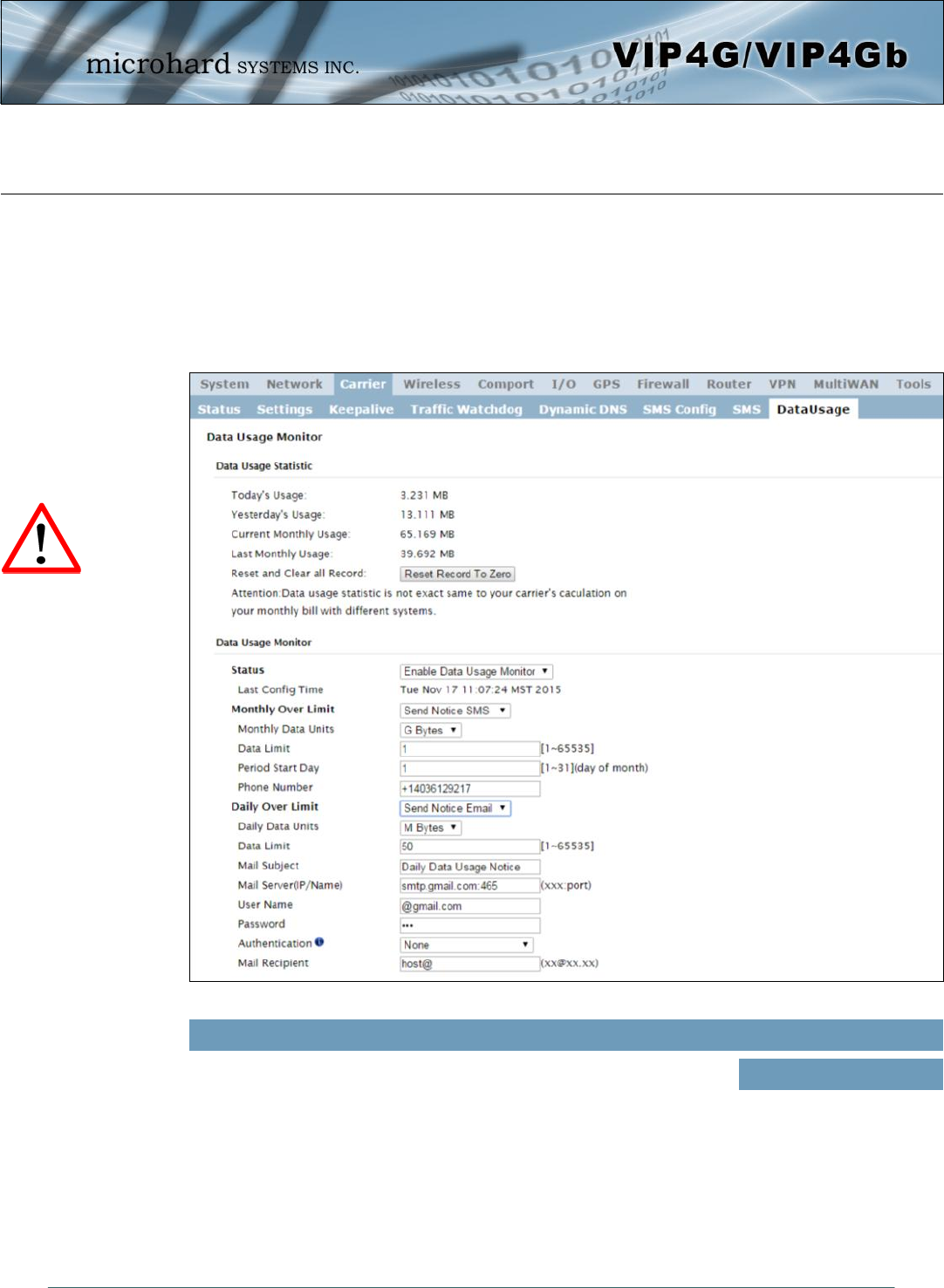
© Microhard Systems Inc. 78
4.0 Configuration
Image 4-3-10: Carrier > Data Usage
4.3.8 Carrier > Data Usage
The Data Usage tool on the VIP4G allows users to monitor the amount of cellular data consumed. Since
cellular devices are generally billed based on the amount of data used, alerts can be triggered by setting
daily and/or monthly limits. Notifications can be sent using SMS or Email, allowing a early warning if
configurable limits are about to be exceeded. The usage data reported by the Data Usage Monitor may not
precisely match the data reported by the carrier, but it gives the users an idea of the bandwidth consumed
by the VIP4G.
Status
Values (selection)
If enabled the VIP4G will track the amount of cellular data consumed. If
disabled, data is not recorded, even in the Current Data Usage display.
Disable
Enable
Set up appropriate firewall
rules to block unwanted data
which may result in excessive
data charges.
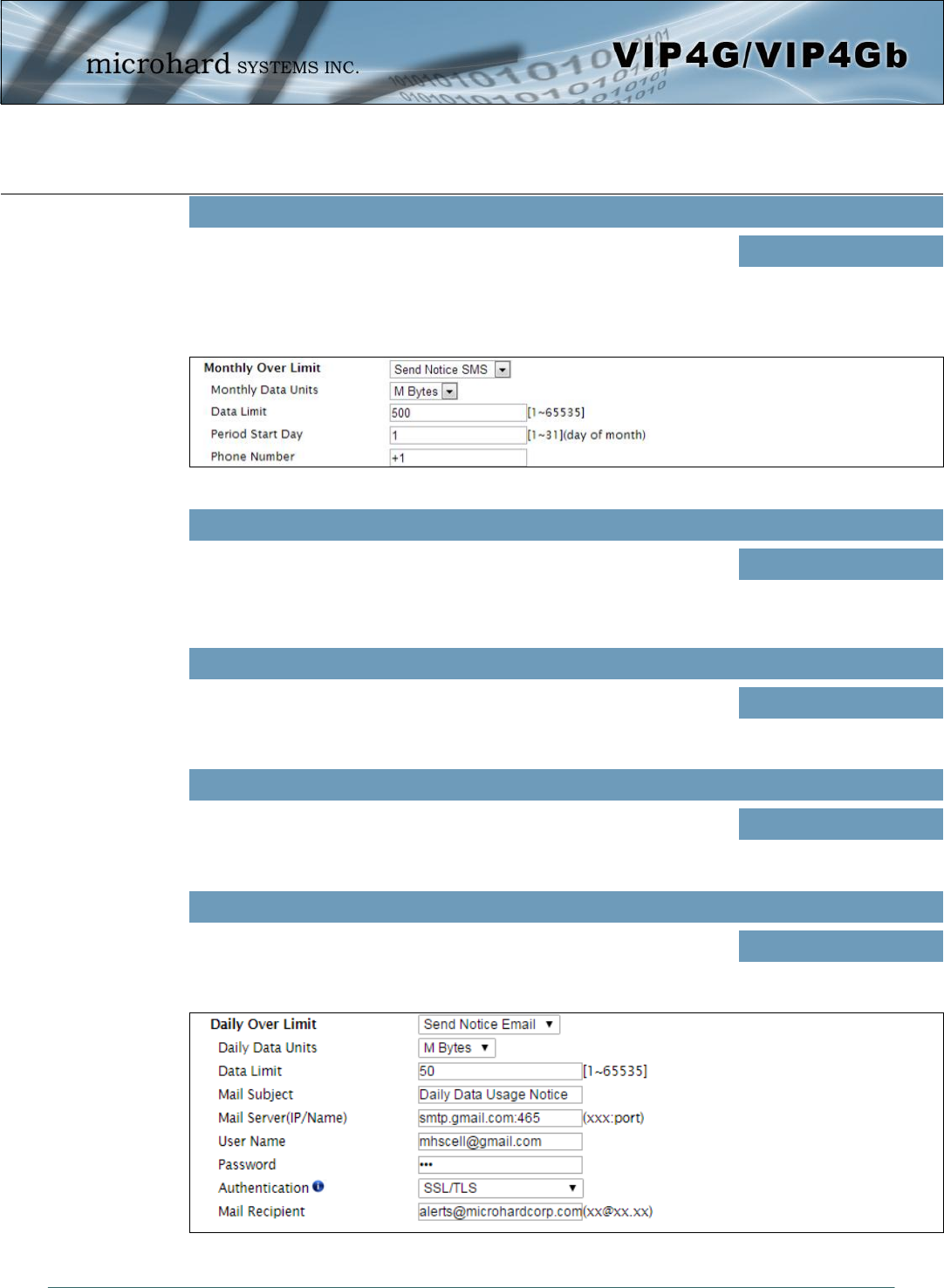
© Microhard Systems Inc. 79
4.0 Configuration
Image 4-3-11: Data Usage > SMS Config
Monthly/Daily Data Unit
Values (selection)
Select the data unit to be used for data usage monitoring.
Bytes / K Bytes / M Bytes
G Bytes
Data Limit
Values (1-65535)
Select the data limit for the day or month, used in connection with the data
unit is the previous field. If you want to set the limit to 250 Mbytes, select M
Bytes for the data unit, and 250 for the data limit. 500
Period Start Day
Values (1-31)
For Monthly tracking, select the day the billing/data cycles begins. On this
day each month the VIP4G will reset the data usage monitor numbers.
1 (Day of Month)
Phone Number
Values (phone)
If SMS is selected as the notification method, enter the phone number to
send any SMS messages generated when the data usage exceeds the
configured limits. +1403
Monthly/Daily Over Limit
Values (selection)
Select the notification method used to send alerts when daily or monthly
thresholds are exceeded. If none is selected, notifications will not be sent,
but data usage will be recorded for reference purposes. None
Send Notice SMS
Send Notice Email
Image 4-3-12: Data Usage > Email Config

© Microhard Systems Inc. 80
4.0 Configuration
Mail Subject
Values (string)
If Email is selected as the notification method, enter the desired email
subject line for the notification email sent when daily and/or monthly usage
limits are exceeded. Daily/Monthly Data Usage
Notice
Mail Server(IP/Name)
Values (xxx:port)
If Email is selected as the notification method, enter the SMTP server
details for the account used to send the Email notifications. Domain or IP
address with the associated port as shown. smtp.gmail.com:465
Username
Values (username)
If Email is selected as the notification method, enter the username of the
Email account used to send Emails.
@gmail.com
Password
Values (string)
If Email is selected as the notification method, enter the password of the
Email account used to send Emails. Most email servers require
authentication on outgoing emails. ***
Mail Recipient
Values (xx@xx.xx)
Enter the email address of the individual or distribution list to send the
email notification to.
host@
Authentication
Values (selection)
Authentication type allows users to specific which, if any, Authentication
type is used to send email via a SMTP server. Ensure that the Mail Server/
Port settings above reflect the correct settings. Contact your provider for
this information if it is not known. None
SSL/TLS
STARTTLS
SSL/TLS + STARTTTLS
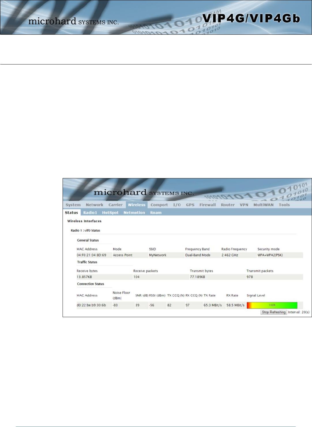
© Microhard Systems Inc. 81
4.0 Configuration
Image 4-4-1: Wireless > Status
4.4 Wireless (WiFi)
4.4.1 Wireless > Status
The Status window gives a summary of all radio or wireless related settings and connections.
The General Status section shows the Wireless MAC address of the current radio, the Operating Mode
(Access Point, Client, Repeater etc), the SSID being used, frequency channel information and the type of
security used.
Traffic Status shows statistics about the transmitted and received data.
The VIP4G shows information about all Wireless connections in the Connection Status section. The
Wireless MAC address, Noise Floor, Signal to Noise ratio (SNR), Signal Strength (RSSI), The transmit and
receive Client Connection Quality (CCQ), TX and RX data rates, and a graphical representation of the
signal level or quality.
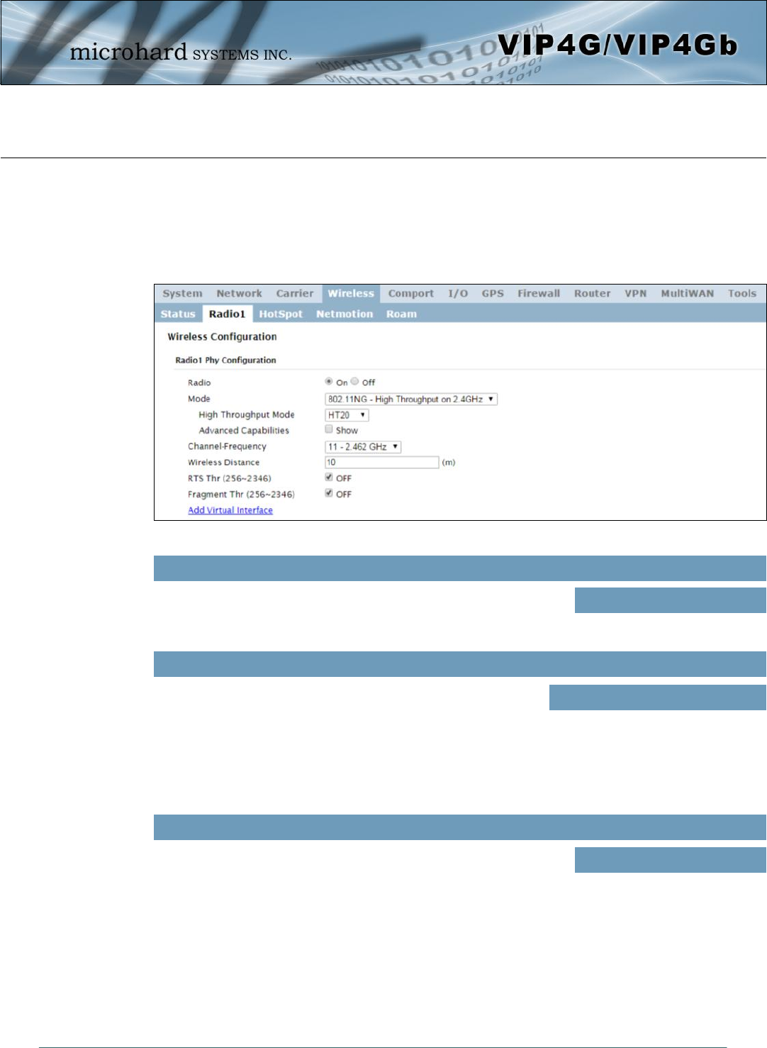
© Microhard Systems Inc. 82
4.0 Configuration
Image 4-4-2: Wireless > Radio Configuration
4.4.2 Wireless > Radio1
Radio1 Phy Configuration
The top section of the Wireless Configuration allows for the configuration of the physical radio module. You
can turn the radio on or off, and select the channel bandwidth and frequency as seen below.
This option is used to turn the radio module on or off. If turned off
Wireless connections can not be made. The default is On.
Radio
Values (selection)
On / Off
The Mode defines which wireless standard to use for the wireless
network. The VIP4G supports all 802.11a/b/g/n modes as seen
here. Select the appropriate operating mode from the list.
The options below are dependant and vary on the operating mode
chosen here.
Mode
Values (selection)
802.11B ONLY
802.11BG
802.11NG-High Throughout 2.4GHz
802.11A ONLY
802.11NA-High Throughout 5GHz
Only appears when using 802.11b, bg or a modes. Lower channel
bandwidths may provide longer range and be less susceptible to noise
but at the trade off of data rates. Higher channel bandwidth may
provide greater data rates but will be more susceptible to noise and
shorter distance potentials.
Channel Bandwidth
Values (selection)
20MHz Normal Rate

© Microhard Systems Inc. 83
4.0 Configuration
Select HT20 for a 20MHz channel, or HT40 for a 40 MHz Channel.
The 40MHz channel is comprised of 2 adjacent 20MHz channels and
the + and—designate to use the higher or lower of the adjacent
channels.
High Throughput Mode
Values (selection)
HT20
HT40-
HT40+
The Channel-Freq setting allows configuration of which channel to operate on, auto can be chosen where
the unit will automatically pick a channel to operate. If a link cannot be established it will try another
channel.
Channel-Freq
2.4 GHz Channels
Auto
Channel 01 : 2.412 GHz
Channel 02 : 2.417 GHz
Channel 03 : 2.422 GHz
Channel 04 : 2.427 GHz
Channel 05 : 2.432 GHz
Channel 06 : 2.437 GHz
Channel 07 : 2.442 GHz
Channel 08 : 2.447 GHz
Channel 09 : 2.452 GHz
Channel 10 : 2.457 GHz
Channel 11 : 2.462 GHz
5 GH Channels
Auto
Channel 36: 5.18 GHz
Channel 40: 5.2 GHz
Channel 44: 5.22 GHz
Channel 48: 5.24 GHz
Channel 149 : 5.745 GHz
Channel 153 : 5.765 GHz
Channel 157 : 5.785 GHz
Channel 161 : 5.805 GHz
Channel 165 : 5.825 GHz
The Wireless Distance parameter allows a user to set the expected
distance the WiFi signal needs to travel. The default is 10km, so the
VIP4G will assume that the signal may need to travel up to 10km so it
sets various internal timeouts to account for this travel time. Longer
distances will require a higher setting, and shorter distances may
perform better if the setting is reduced.
Wireless Distance
Values (meters)
10000
Advanced Capabilities (Only shown if box is checked)
MPDU Aggregation (Enable/Disable) - Allows multiple data frames to be sent in a single transmission
block, allowing for acknowledging or retransmitting if errors occur.
Short GI (Enable/Disable) - GI (guard interval) is the time the receiver waits for any RF reflections to settle
before sampling data. Enabling a short GI (400ns) can increase throughput, but can also increase the error
rate in some installations.
HT Capabilities Info - TX-STBC RX-STBC1 DSSS_CCK-40
Maximum AMSDU (byte) - 3839
Maximum AMPDU (byte) - 65535
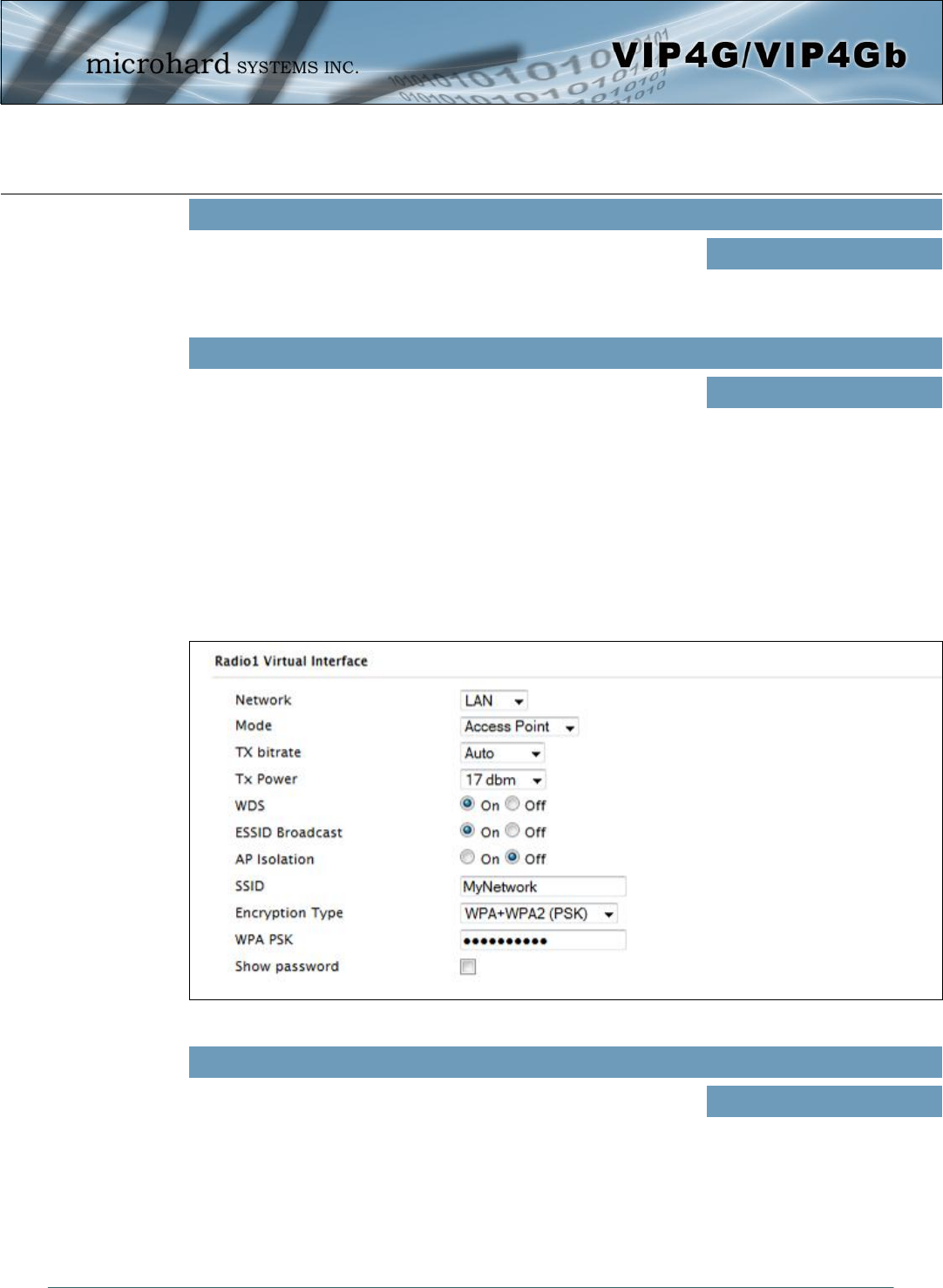
© Microhard Systems Inc. 84
4.0 Configuration
Once the RTS Threshold defined packet size is reached, the system
will invoke RTS/CTS flow control. A large RTS Threshold will improve
bandwidth, while a smaller RTS Threshold will help the system recover
from interference or collisions caused by obstructions.
RTS Thr (256 ~ 2346)
Values (selection)
On / OFF
The Fragmentation Threshold allows the system to change the
maximum RF packet size. Increasing the RF packet size reduces the
need to break packets into smaller fragments. Increasing the
fragmentation threshold slightly may improve performance if a high
packet error rate is experienced.
Fragment Thr (256 ~ 2346)
Values (selection)
On / OFF
Image 4-4-3: Wireless > Radio Configuration
Radio1 Virtual Interface
The bottom section of the Wireless Configuration provides for the configuration of the Operating Mode of
the Wireless Interface, the TX power, Wireless Network information, and Wireless Encryption. The VIP4G
can support multiple virtual interfaces. These interfaces provide different SSID’s for different users, and
can also be assigned to separate subnets (Network Interfaces) to prevent groups from interacting.
Choose between LAN or WIFI for the Virtual Interface. If additional
Network Interfaces have been defined in the Network > LAN section,
the Interface name will also appear here.
Network
Values (selection)
LAN
WIFI
(Additional Interfaces…)

© Microhard Systems Inc. 85
4.0 Configuration
This setting determines the rate at which the data is to be wirelessly transferred.
The default is ‘Auto’ and, in this configuration, the unit will transfer data at the highest possible rate in
consideration of the receive signal strength (RSSI).
Setting a specific value of transmission rate has the benefit of ‘predictability’ of that rate, but if the RSSI
drops below the required minimum level to support that rate, communications will fail.
TX Rate
802.11a
Auto
6 Mbps
9 Mbps
12 Mbps
18 Mbps
24 Mbps
36 Mbps
48 Mbps
54 Mbps
802.11 b/g
Auto
1 Mbps (802.11b,g)
2 Mbps (802.11b,g)
5.5 Mbps (802.11b,g)
11 Mbps (802.11b,g)
6 Mbps (802.11g)
9 Mbps (802.11g)
12 Mbps (802.11g)
18 Mbps (802.11g)
24 Mbps (802.11g)
36 Mbps (802.11g)
48 Mbps (802.11g)
54 Mbps (802.11g)
802.11n (HT20/HT40)
Auto
mcs-0 (7.2/15) Mbps
mcs-1 (14.4/30.0) Mbps
mcs-2 (21.7/45.0) Mbps
mcs-3 (28.9/60.0) Mbps
mcs-4 (43.3/90.0) Mbps
mcs-5 (57.8/120.0) Mbps
mcs-6 (65.0/135.0) Mbps
mcs-7 (72.2/150.0) Mbps
mcs-8 (14.4/30.0) Mbps
mcs-9 (28.9/60.0) Mbps
mcs-10 (43.3/90.0) Mbps
mcs-11 (57.8/120.0) Mbps
mcs-12 (86.7/180.0) Mbps
mcs-13 (115.6/240.0) Mbps
mcs-14 (130.3/270.0) Mbps
mcs-15 (144.4/300.0) Mbps
Access Point - An Access Point may provide a wireless data
connection to many clients, such as stations, repeaters, or other
supported wireless devices such as laptops etc.
If more than 1 Virtual Interface (more than 1 SSID) has been defined,
the VIP4G can ONLY operate as a Access Point, and will be locked
into this mode.
Mode
Values (selection)
Access Point
Client
Repeater
Station/Client - A Station may sustain one wireless connection, i.e. to an Access Point.
Repeater - A Repeater can be connected to an Access Point to extend the range and provide a
wireless data connection to many clients, such as stations.

© Microhard Systems Inc. 86
4.0 Configuration
This setting establishes the transmit power level which will be
presented to the antenna connectors at the rear of the VIP4G. Unless
required, the Tx Power should be set not for maximum, but rather for
the minimum value required to maintain an adequate system fade
margin.
TX Power
Values (selection)
11 dBm
12 dBm
13 dBm
14 dBm
15 dBm
16 dBm
17 dBm
18 dBm
19 dBm
20 dBm
21 dBm
22 dBm
23 dBm
24 dBm
25 dBm
26 dBm
27 dBm
28 dBm
29 dBm
30 dBm
Refer to FCC (or as
otherwise applicable)
regulations to ascertain,
and not operate beyond,
the maximum allowable
transmitter output power
and effective isotropic
radiated power (EIRP).
Wireless distribution system (WDS) is a system enabling the wireless
interconnection of access points. WDS preserves the MAC addresses
of client frames across links between access points
WDS
Values (selection)
On / Off
Disabling the SSID broadcast helps secure the wireless network.
Enabling the broadcast of the SSID (Network Name) will permit others
to ‘see’ the wireless network and perhaps attempt to ‘join’ it.
ESSID Broadcast
Values (selection)
On / Off
SSID: Service Set Identifier.
The ‘name’ of a wireless
network. In an open wireless
network, the SSID is
broadcast; in a closed system
it is not. The SSID must be
known by a potential client for
it to be able to access the
wireless network.
All devices connecting to the VIP4G in a given network must use the
SSID of the VIP4G. This unique network address is not only a security
feature for a particular network, but also allows other networks - with
their own unique network address - to operate in the same area
without the possibility of undesired data exchange between networks.
SSID
Values (string)
wlan0
Change the default value for
the Network Name to
something unique for your
network. Do this for an
added measure of security
and to differentiate your
network from others which
may be operating nearby.
When AP Isolation is enabled wireless devices connected to this SSID
will not be able to communicate with each other. In other words if the
VIP4G is being used as a Hot Spot for many wireless clients, AP
Isolation would provide security for those clients by not allowing
access to any other wireless device.
AP Isolation
Values (selection)
On / Off

© Microhard Systems Inc. 87
4.0 Configuration
The MAC filter allows the control of which WIFI devices can, or cannot
connect to the VIP4G. If set to Allow, only the MAC Addresses listed
will be allowed to connect, all others will be blocked. When set to
Deny, only the devices (via MAC) will be blocked.
MAC Filter
Values (selection)
Disabled / Allow / Deny
The encryption types defines the type of security used for the Wireless
Interface, to join a network a device must know the correct password/
passphrase/key.
Security options are dependent on the version type. This section
describes all available options. Export versions may not have all
optional available to meet regulatory requirements set government
policies.
Encryption Type
Values (selection)
Disabled
WPA (PSK)
WPA2 (PSK)
WPA+WPA2 (PSK)
WPA Enterprise (RADIUS)
WPA2 Enterprise (RADIUS)
WPA+WPA2 Enterprise(RADIUS)
Check this box to show the currently configured password for WPA/
WPA2 encryption passphrase.
Show Password
Values (selection)
unchecked
This is the password, or preshared key that is required by any device
to connect to the wireless interface of the VIP4G. It is strongly
recommended to always have a password defined, and changed from
the factory default.
WPA PSK
Values (string)
0123456789
If using Enterprise (RADIUS) encryption, enter the IP Address of the
RADIUS authentication server here.
RADIUS IP Address
Values (IP Address)
(no default)
If using Enterprise (RADIUS) encryption, enter the port number of the
RADIUS authentication server here.
RADIUS Port
Values (port)
(no default)
This is the password, or preshared key that is required by any device
to connect to the wireless interface of the VIP4G. It is strongly
recommended to always have a password defined, and changed from
the factory default.
RADIUS Server Key
Values (selection)
0123456789
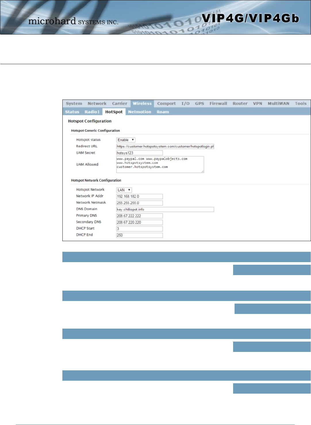
© Microhard Systems Inc. 88
4.0 Configuration
Image 4-4-5: Wireless > Hotspot
4.4.3 Wireless > HotSpot
The Wireless Hotspot configuration is used when providing public hotspot services and it is required to use
a server or web based authentication service to verify users.
Use this option to enable or disable the hotspot authentication service.
Hotspot Status
Values (selection)
Enable / Disable
This is a secret password between the Redirect URL and the Hotspot
given by the hotspot provider.
UAM Secret
Values
hotsys123
Specify the hotspot URL as given by your service provider. The
address of the UAM Server, the authentication portal.
Redirect URL
Values
(varies)
UAM Allowed is a list of websites that unauthenticated users are
allowed to access.
UAM Allowed
Values
(varies)

© Microhard Systems Inc. 89
4.0 Configuration
Specify the IP Address of the Hotspot application. All hotspot clients
will get an IP address in the same network as the Hotspot.
Network IP Address
Values
192.168.182.0
Specify the Netmask of the Hotspot application. All hotspot clients will
get an IP address in the same network as the Hotspot.
Network Netmask
Values
255.255.255.0
Provide your service providers 1st DNS Server domain.
DNS Domain
Values
Key.chillispot.info
Specify the Primary DNS server to be used by devices connected to
the Hotspot network.
Primary DNS
Values
208.67.222.222
Specify the Secondary DNS server to be used by devices connected
to the Hotspot network.
Secondary DNS
Values
208.67.222.220
When devices connect to the BulletPlus WiFi and Hotspot is enabled,
the Hotspot will assign the IP addresses to the connected devices,
select the starting range here.
DHCP Start
Values
3
When devices connect to the BulletPlus WiFi and Hotspot is enabled,
the Hotspot will assign the IP addresses to the connected devices,
select the ending range here.
DHCP End
Values
250
Hotspot Network Configuration
This field is used to specify which configured network is bonded to the
hotspot. Sub networks can be created in the Network > LAN menu,
which are dedicated to the hotspot devices.
*The DHCP service for the network used should be turned off as all IP
address assignments will be made by the hotspot service provider.*
Hotspot Network
Values
Varies
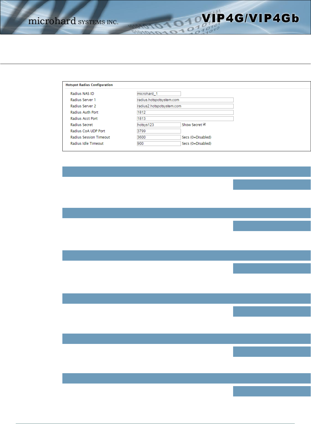
© Microhard Systems Inc. 90
4.0 Configuration
Image 4-4-5: Wireless > Hotspot Radius Configuration
This is the RADIUS name of your Hotspot as given by your Hotspot
Service Provider.
Radius NAS ID
Values
Microhard_1
Hotspot Radius Configuration
As assigned by the Hotspot Service Provider, the name or IP address
of the primary RADIUS Server.
Radius Server 1
Values
radius.hotspotsystem.com
As assigned by the Hotspot Service Provider, the name or IP address
of the alternate RADIUS Server.
Radius Server 2
Values
radius2.hotspotsystem.com
The Radius Authentication Port Number. The default is 1812. This is
provided by your Hotspot service provider.
Radius Auth Port
Values
1812
The Radius Account Port Number. The default is 1813. This is
provided by your Hotspot service provider.
Radius Acct Port
Values
1813
Also called a shared key, this is the RADIUS password assigned by
you Hotspot provider.
Radius Secret
Values
hotsys123

© Microhard Systems Inc. 91
4.0 Configuration
Specify the Radius CoA UDP Port here. This information is supplied by
the hotspot service provider.
Radius CoA UDP Port
Values (port)
3799
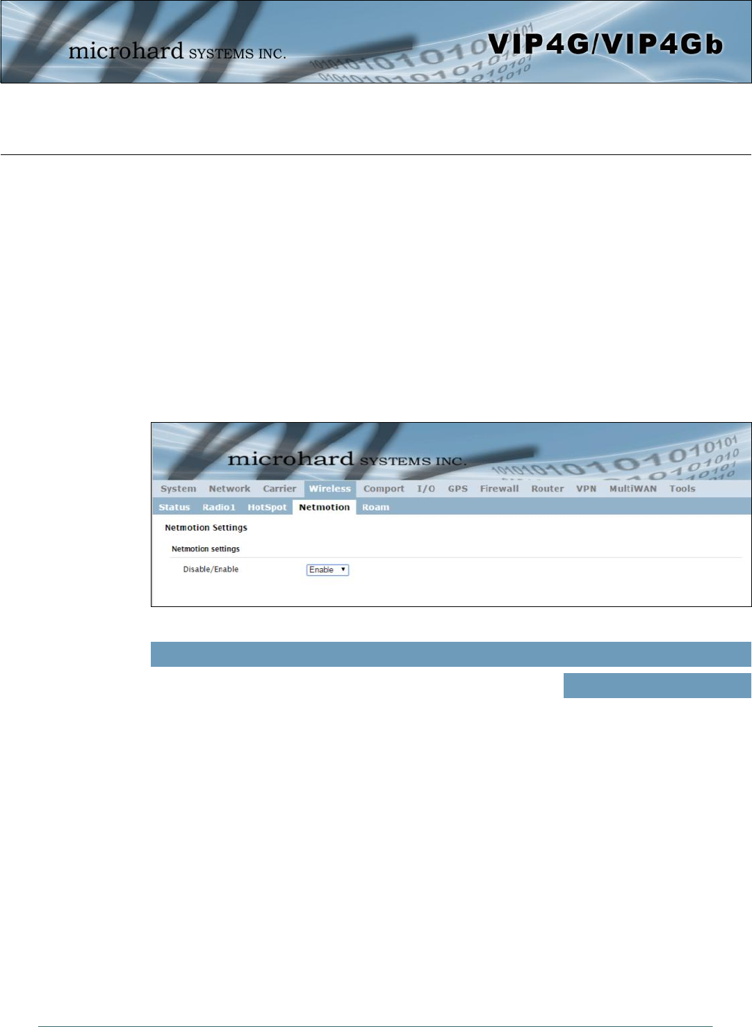
© Microhard Systems Inc. 92
4.0 Configuration
Image 4-4-6: Wireless > Netmotion
4.4.4 Wireless > Netmotion
Netmotion allows the modem to use the WIFI interface for a default data connection rather than the cellular
connection, when available. This is done by changing the default route between the Carrier and WIF
networks. When Netmotion is enabled the modem will attempt to use the WIFI connection as a WAN
connection for data first, and if that connection fails, or is not available, the modem will use the Cellular
connection. Up to 10 previously used networks can be used under Roaming for mobile applications.
For Netmotion to be used the modem must be configured to meet the following prerequisites.
- The Network > WIFI interface must be configured.
- The WIFI interface must be bound to Radio1 in the Wireless > Radio1 menu
- The Wireless interface must be setup as a Station/Client
When Netmotion is enabled, the Wireless interface cannot be used as a Access Point for other devices to
connect to.
Use this option to enable or disable the Netmotion functionality of the
modem.
Disable/Enable
Values (selection)
Enable / Disable
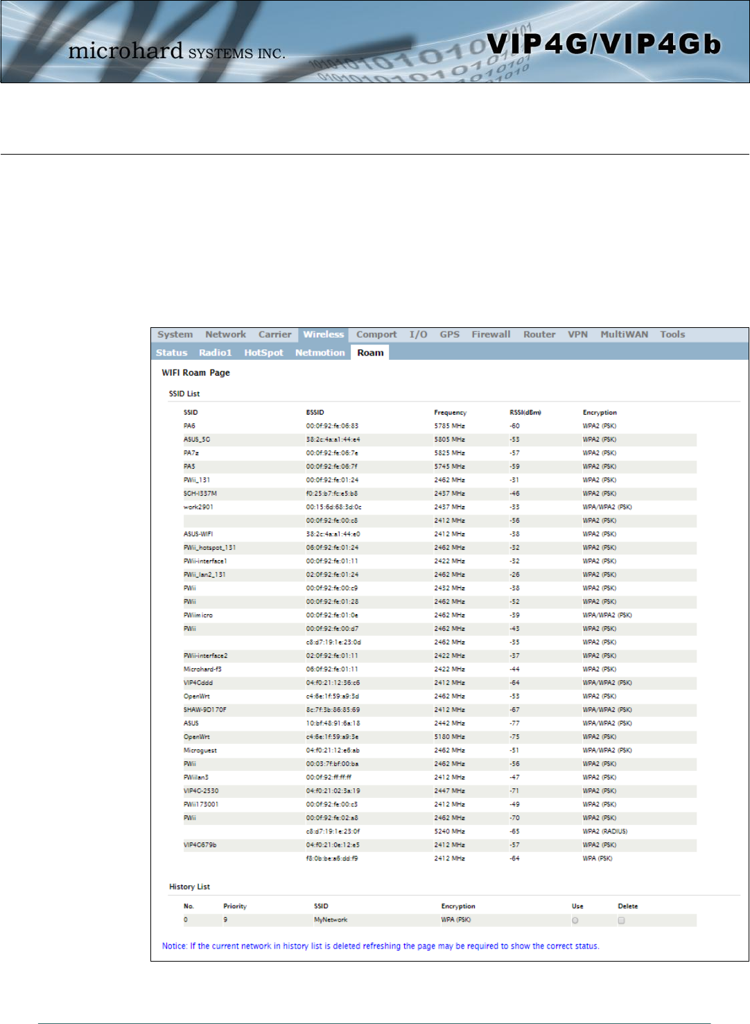
© Microhard Systems Inc. 93
4.0 Configuration
Image 4-4-7: Wireless > Roam
4.4.5 Wireless > Roam
The Roam menu is used in conjunction with Netmotion. When the modem is connected to a AP (Access
Point), the Roaming page will only display the currently connected network, and the History List of
previously used networks. If the modem is not currently connected to a Wireless Network, Roam will
display all available APs (Access Points) in range, as well as the history list of previously used networks.
The last 10 configured APs will be displayed in the list and will be automatically used if they are available.
This is ideal for mobile applications, where the modem will be moving from place to place. Unwanted
networks can be removed from the history list to prevent the modem from using it.
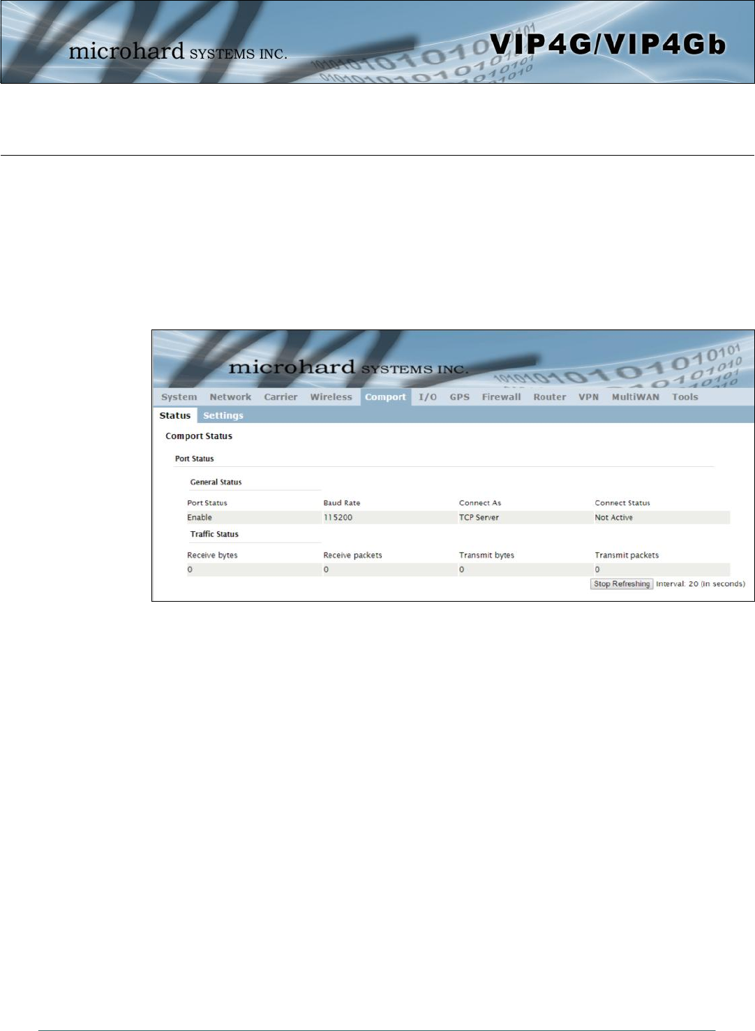
© Microhard Systems Inc. 94
4.0 Configuration
Image 4-5-1: Comport > Comport Status
4.5 Comport
4.5.1 Comport > Status
The Status window gives a summary of the Serial port on the VIP4G. The Status window shows if the com
port has been enabled, how it is configured (Connect As), and the connection status.
Also shown is statistical information about the serial port, including the number of transmitted and received
packets and bytes. This can be used to diagnose connection and data usage issues.
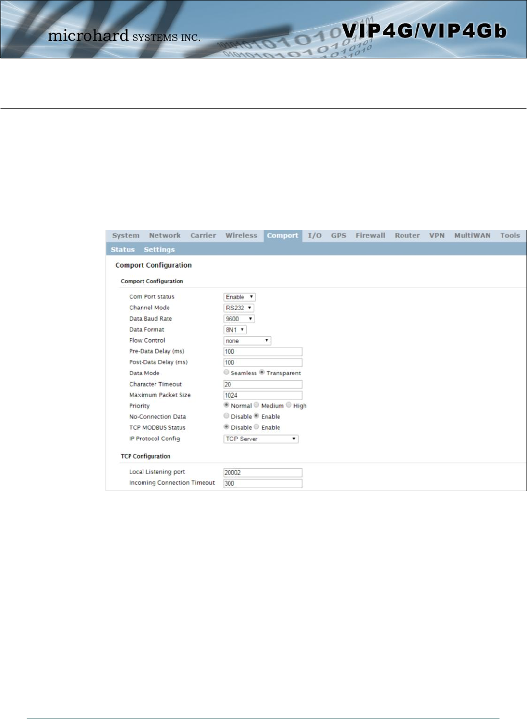
© Microhard Systems Inc. 95
4.0 Configuration
Image 4-5-2: Comport > Settings Configuration
4.5.2 Comport > Settings
This menu option is used to configure the serial device server for the serial communications port. Serial
device data may be brought into the IP network through TCP, UDP, or multicast; it may also exit the VIP4G
network on another VIP4G serial port. The fully-featured RS232 interface supports hardware handshaking.
Basic configuration of the serial port would be to first, set the appropriate interface connection settings
such as the baud rate and data format. Next, it is critical to define the IP Protocol Config, since all serial
data entering the VIP4G is essentially converted to IP, to either TCP, or UDP packets. The following
section describes the configuration of the serial port.
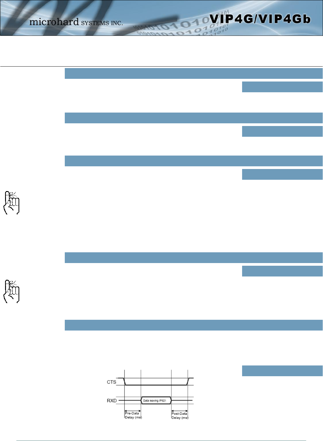
© Microhard Systems Inc. 96
4.0 Configuration
Select operational status of the Serial Port. The port is disabled by
default, to allow the port to be used for console and AT command
operations. If it is required to connect to a serial based device, the port
first must be enabled.
Com Port Status
Values (selection)
Disabled / Enable
Determines which serial interface shall be used to connect to external
devices: RS232, RS485, or RS422. When an interface other than
RS232 is selected, the DE9 port will be inactive.
Channel Mode
Values (selection)
RS232 / RS485 / RS422
The serial baud rate is the rate at which the modem is to communicate
with the attached local asynchronous device.
Data Baud Rate
Values (bps)
Note: Most PCs do not
readily support serial
communications greater than
115200bps.
921600
460800
230400
115200
57600
38400
28800
19200
14400
9600
7200
4800
3600
2400
1200
600
300
This setting determines the format of the data on the serial port.
The default is 8 data bits, No parity, and 1 Stop bit.
Data Format
Values (selection)
8N1
8N2
8E1
8O1
7N1
7N2
7E1
7O1
7E2
7O2
Flow control may be used to enhance the reliability of serial data communications, particularly at higher
baud rates. If the attached device does not support hardware handshaking, leave this setting at the default
value of ‘None’. When CTS Framing is selected, the VIP4G uses the CTS signal to gate the output data on
the serial port.
Flow Control
Values (selection)
None
Hardware
CTS Framing
Software flow control (XON/
XOFF) is not supported.
Drawing 4A: CTS Output Data Framing
© Microhard Systems Inc. 97
4.0 Configuration
Refer to Drawing 4A on the preceding page.
Pre-Data Delay
Values (time (ms) )
100
Refer to Drawing 4A on the preceding page.
Post-Data Delay
Values (time (ms) )
100
This setting defines the serial output data framing. In Transparent
mode (default), the received data will be output promptly from the
VIP4G.
Date Mode
Values (selection)
Seamless / Transparent
When set to Seamless, the serial port server will add a gap between data frames to comply with the
MODBUS protocol for example. See ‘Character Timeout’ below for related information.
In Seamless mode (see Data Mode described on the preceding page),
this setting determines when the serial server will consider the recently
-received incoming data as being ready to transmit. As per the
MODBUS standard, frames will be marked as ‘bad’ if the time gap
between frames is greater than 1.5 characters, but less than the
Character Timeout value.
Character Timeout
Values (characters)
0
The serial server also uses this parameter to determine the time gap inserted between frames. It is
measured in ‘characters’ and related to baud rate.
Example: If the baud rate is 9600bps, it takes approximately 1ms to move one character. With the
Character Timeout set to 4, the timeout period is 4ms. When the calculated time is less than 3.5ms, the
serial server will set the character timeout to a minimum value of 3.5ms.
If the baud rate is greater than 19200bps, the minimum character timeout is internally set to 750us
(microseconds).
Defines the buffer size that the serial server will use to receive data
from the serial port. When the server detects that the Character
Timeout criteria has been met, or the buffer is full, it packetizes the
received frame and transmits it.
Maximum Packet Size
Values (bytes)
1024
This setting effects the quality of service associated with the data
traffic on the COM port.
Priority
Values (selection)
Normal / Medium / High
© Microhard Systems Inc. 98
4.0 Configuration
When enabled the data will continue to buffer received on the serial
data port when the radio loses synchronization. When disabled the
VIP4G will disregard any data received on the serial data port when
radio synchronization is lost.
No-Connection Data
Values (selection)
Disable / Enable
This option will enable or disable the MODBUS decoding and
encoding features.
MODBUS TCP Status
Values (selection)
Disable / Enable
The field allows the MODBUS TCP Protection Status flag to be
enabled or disabled. If enabled the MODBUS data will be encrypted
with the MODBUS Protection Key.
MODBUS TCP Protection
Values (selection)
Disable / Enable
MODBUS encryption key used for the MODBUS TCP Protection
Status feature.
MODBUS TCP Protection Key
Values (string)
1234

© Microhard Systems Inc. 99
4.0 Configuration
This setting determines which protocol the serial server will use to
transmit serial port data over the VIP4G network.
The protocol selected in the IP Protocol Config field will determine
which configuration options appear in the remainder of the COM1
Configuration Menu.
The serial port will not work unless the IP Protocol Config has been
configured properly. Once serial data is collected at the serial port, the
modem must be told how to deal with it, and where to send it.
IP Protocol Config
Values (selection)
TCP Client
TCP Server
TCP Client/Server
UDP Point-to-Point
SMTP Client
SMS Transparent Mode
GPS Transparent Mode
The protocol selected in the
IP Protocol Config field will
determine which configuration
options appear in the
remainder of the COM1
Configuration Menu.
TCP Client: When TCP Client is selected and data is received on its serial port, the VIP4G takes the
initiative to find and connect to a remote TCP server. The TCP session is terminated by this same unit
when the data exchange session is completed and the connection timeout has expired. If a TCP
connection cannot be established, the serial port data is discarded.
Remote Server Address
IP address of a TCP server which is ready to accept serial port data through a TCP
connection. For example, this server may reside on a LAN network server.
Default: 0.0.0.0
Remote Server Port
A TCP port which the remote server listens to, awaiting a session connection request from
the TCP Client. Once the session is established, the serial port data is communicated from
the Client to the Server.
Default: 20001
Outgoing Connection Timeout
This parameter determines when the VIP4G will terminate the TCP connection if the
connection is in an idle state (i.e. no data traffic on the serial port).
Default: 60 (seconds)
TCP Server: In this mode, the VIP4G Series will not INITIATE a session, rather, it will wait for a Client to
request a session of it (it’s being the Server—it ‘serves’ a Client). The unit will ‘listen’ on a specific TCP
port. If a session is established, data will flow from the Client to the Server, and, if present, from the Server
to the Client. If a session is not established, both Client-side serial data, and Server-side serial data , if
present, will be discarded.
Local Listening Port
The TCP port which the Server listens to. It allows a TCP connection to be created by a TCP
Client to carry serial port data.
Default: 20001
Incoming Connection Timeout
Established when the TCP Server will terminate the TCP connection is the connection is in
an idle state.
Default: 300 (seconds)
UDP: User Datagram
Protocol does not provide
sequencing information for
the packets sent nor does it
establish a
’connection’ (‘handshaking’)
and is therefore most suited
to communicating small
packets of data.
TCP: Transmission Control
Protocol in contrast to UDP
does provide sequencing
information and is connection
-oriented; a more reliable
protocol, particularly when
large amounts of data are
being communicated.
Requires more bandwidth
than UDP.

© Microhard Systems Inc. 100
4.0 Configuration
IP Protocol Config (Continued…)
TCP Client/Server: In this mode, the VIP4G will be a combined TCP Client and Server, meaning that it
can both initiate and serve TCP connection (session) requests. Refer to the TCP Client and TCP Server
descriptions and settings described previously as all information, combined, is applicable to this mode.
UDP Point-to-Point: In this configuration the VIP4G will send serial data to a specifically-defined point,
using UDP packets. This same VIP4G will accept UDP packets from that same point.
Remote IP Address
IP address of distant device to which UDP packets are sent when data received at serial port.
Default: 0.0.0.0
Remote Port
UDP port of distant device mentioned above.
Default: 20001
Listening Port
UDP port which the IP Series listens to (monitors). UDP packets received on this port are
forwarded to the unit’s serial port.
Default: 20001
SMTP Client: If the VIP4G has Internet access, this protocol may be used to send the data received on
the serial port (COM1), in a selectable format (see Transfer Mode (below)), to an e-mail addressee. Both
the SMTP Server and the e-mail addressee must be ‘reachable’ for his feature to function.
Mail Subject
Enter a suitable ‘e-mail subject’ (e-mail heading).
Default: COM1 Message
Mail Server (IP/Name)
IP address or ‘Name’ of SMTP (Mail) Server.
Default: 0.0.0.0
Mail Recipient
A valid e-mail address for the intended addressee, entered in the proper format.
Default: host@
Message Max Size
Maximum size for the e-mail message.
Default: 1024
Timeout (s)
How long the unit will wait to gather data from the serial port before sending an e-mail
message; data will be sent immediately upon reaching Message Max Size.
Default: 10
Transfer Mode
Select how the data received on COM1 is to be sent to the email addressee. Options
are: Text, Attached File, Hex Code.
Default: Text
A UDP or TCP port is an
application end-point. The IP
address identifies the device
and, as an extension of the IP
address, the port essentially
‘fine tunes’ where the data is
to go ‘within the device’.
Be careful to select a port
number that is not
predetermined to be
associated with another
application type, e.g. HTTP
uses port 80.