Microhard Systems VIP4GABGN20 LTE Ethernet Bridge / Serial Gateway User Manual
Microhard Systems Inc LTE Ethernet Bridge / Serial Gateway
Contents
- 1. User manual
- 2. User Manual 1 of 2
- 3. User Manual 2 of 2
User manual
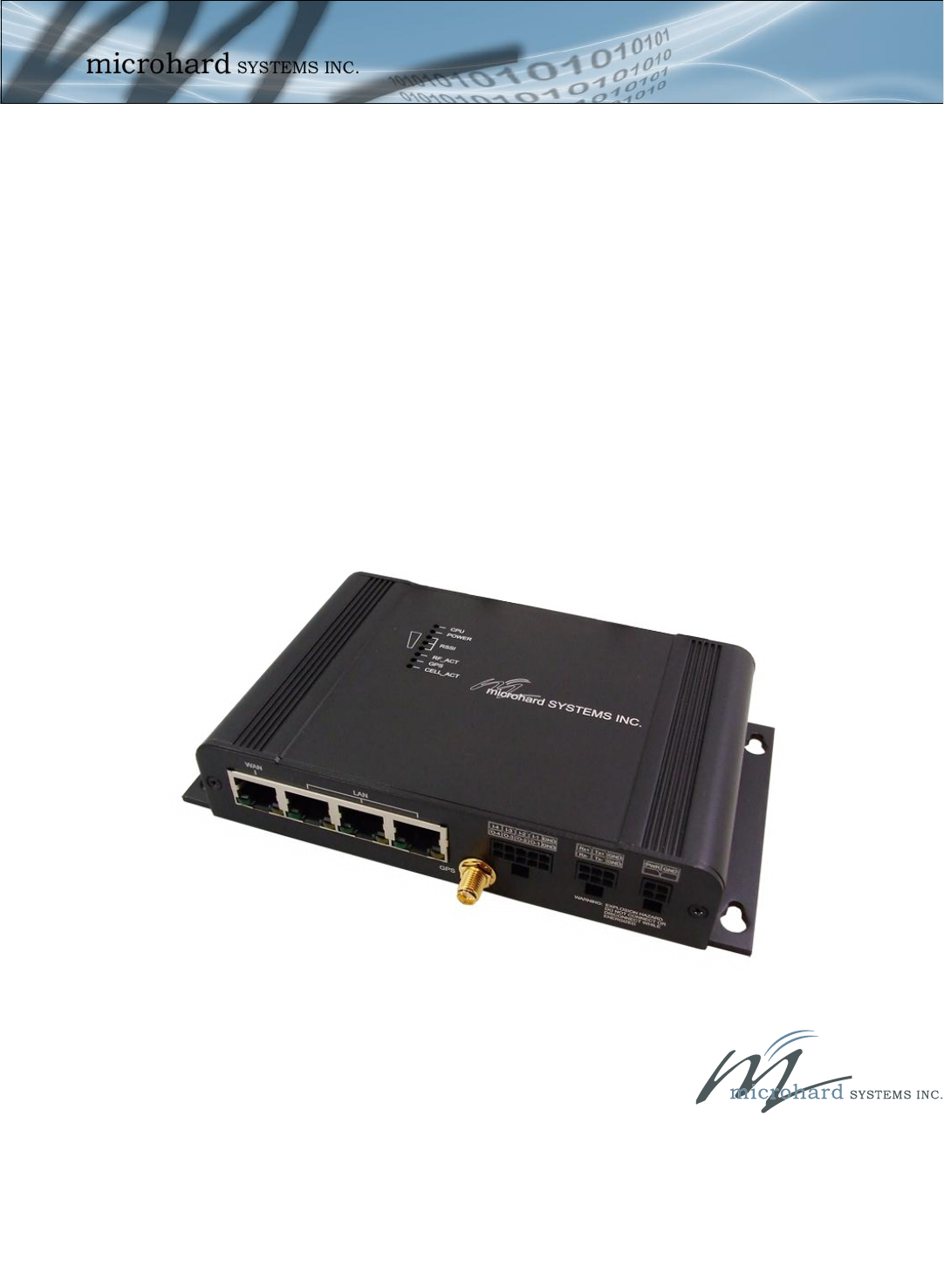
VIP4G
VIP4G LTE Ethernet Bridge/Serial Gateway
Document: VIP4G User Guide.v1.0.pdf
FW Version: 1.1.6-r1114
User Guide
December 2012
150 Country Hills Landing NW
Calgary, Alberta
Canada T3K 5P3
Phone: (403) 248-0028
Fax: (403) 248-2762
www.microhardcorp.com

© Microhard Systems Inc. 2
Revision History
Revision Description Initials Date
1.0 Initial Release PEH Dec 2012
FCC/ICRegulatoryNotice
Modificationstatement:
MicrohardSystemsInchasnotapprovedanychangesormodificationstothisdevicebytheuser.Any
changesormodificationscouldvoidtheuser’sauthoritytooperatetheequipment.
Interferencestatement:
ThisdevicecomplieswithPart15oftheFCCRulesandIndustryCanadalicence‐exemptRSSstandard(s).Operationissubjectto
thefollowingtwoconditions:(1)thisdevicemaynotcauseinterference,and(2)thisdevicemustacceptanyinterference,
includinginterferencethatmaycauseundesiredoperationofthedevice.
RadiationExposureStatement:
IPn4GcomplieswithFCC/ICradiationexposurelimitssetforthforanuncontrolledenvironmentandmeetstheFCCradio
frequency(RF)ExposureGuidelinesinSupplementCtoOET65andRSS‐102oftheICradiofrequency(RF)Exposurerules.
Nevertheless,theproductshouldbeusedinsuchamannerthatthepotentialforhumancontactduringnormaloperationis
minimized.Thisequipmentshouldbeinstalledandoperatedwithminimumdistanceof20cmbetweentheradiatorandany
personandmustnotbecollocatedwithothertransmittersexceptotherwiseauthorised.
Thisdeviceisapprovedtobeusedwithadipoleantennawithamaximumgainof2dBi.
Thisproductintegratesandisauthorizedtobeco‐locatedwithaNovatelWireless'Expedite®E371PCIExpressMiniCard(FCC
ID:PKRNVWE371,IC:3229A‐E371).TheNovatelWireless'Expedite®E371PCIExpressMiniCardisgrantedwithamodular
approvalformobileapplications.Integrationhasbeendonemeetingthefollowingconditions:
1.Atleast20cmseparationdistancebetweentheantennaandanypersonbodyismaintainedatalltimes.
2.TocomplywithFCC/ICregulationslimitingbothmaximumRFoutputpowerandhumanexposuretoRFradiation,the
maximumantennagainincludingcablelossinamobileonlyexposureconditiondoesnotexceed3.5dBifor850MHzfrequency
band,5.0dBifor700MHzfrequencyband,5.0dBifor1700MHzfrequencybandand3.0dBifor1900MHzfrequencyband.
3.TheNovatelWireless'Expedite®E371PCIExpressMiniCardantennaisnotco‐locatedwithanyotherantennasexcept
withtheantennaoftheIPn4Gproduct.
FCCClassAdigitaldevicenotice
ThisequipmenthasbeentestedandfoundtocomplywiththelimitsforaClassAdigitaldevice,pursuanttopart15oftheFCC
Rules.Theselimitsaredesignedtoprovidereasonableprotectionagainstharmfulinterferenceinaresidentialinstallation.This
equipmentgenerates,usesandcanradiateradiofrequencyenergyand,ifnotinstalledandusedinaccordancewiththe
instructions,maycauseharmfulinterferencetoradiocommunications.However,thereisnoguaranteethatinterferencewill
notoccurinaparticularinstallation.Ifthisequipmentdoescauseharmfulinterferencetoradioortelevisionreception,which
canbedeterminedbyturningtheequipmentoffandon,theuserisencouragedtotrytocorrecttheinterferencebyoneor
moreofthefollowingmeasures:
‐ Reorientorrelocatethereceivingantenna.
‐ Increasetheseparationbetweentheequipmentandreceiver.
‐ Connecttheequipmentintoanoutletonacircuitdifferentfromthattowhichthereceiverisconnected.
‐ Consultthedealeroranexperiencedradio/TVtechnicianforhelp.
FCC/ICAvisréglementaire
Instructiondemodification:
MicrohardSystemsIncn'apasapprouvélesmodificationsapportéesàcetappareilparl'utilisateur.Leschangementsou
modificationspourraientannulerl'autoritédel'utilisateuràutilisercetéquipement.
Déclarationsurlesinterférences:
CetappareilestconformeàlaPartie15delaréglementationFCCetIndustrieCanadaexemptsdelicenceRSSnorme(s).Son
fonctionnementestsoumisauxdeuxconditionssuivantes:(1)cetappareilnedoitpasprovoquerd'interférences,et(2)cet
appareildoitacceptertouteinterférence,ycomprislesinterférencespouvantprovoquerunfonctionnementindésirablede
l'appareil.
Déclarationd'expositionauxradiations:
VIP4Gestconformeàl'expositionauxradiationsFCC/ICdéfiniespourunenvironnementnoncontrôléetrépondauxdirectives
d'expositiondelafréquencedelaFCCradiofréquence(RF)dansleSupplémentCàOET65etRSS‐102delafréquenceradio(RF)
ICrèglesd'exposition.Néanmoins,leproduitdoitêtreutiliséd'unemanièretellequelepotentielpourlecontacthumain
pendantl'utilisationnormalesoitminimisé.Cetéquipementdoitêtreinstalléetutiliséàunedistanceminimumde20cmentre
leradiateurettoutepersonneetnedoitpasêtreco‐implantéavecd'autresémetteurs,saufautorisationcontraire.
Cedispositifestapprouvépourêtreutiliséavecuneantennedipôleavecungainmaximumde2dBi.
Ceproduitintègreetestautoriséàêtreco‐localisésavecuneNovatelWirelessExpedite®E371PCIExpressMiniCard(FCCID:
PKRNVWE371,IC:3229A‐E371).LeNovatelWirelessExpedite®E371PCIExpressMiniCardestaccordéeàunagrément
modulairepourlesapplicationsmobiles.L'intégrationaétéfaitauxconditionssuivantes:
1.Aumoins20cmdedistancedeséparationentrel'antenneettoutepersonnecorpsestmaintenueentouttemps.
2.PourseconformeràlaFCC/ICrèglementsquilimitentàlafoislapuissancemaximaledesortieRFetl'expositionhumaine
auxrayonnementsRF,legainmaximaldel'antenne,ycomprislapertedecâbledansuneconditiond'expositionseulement
mobilenedépassepas3,5dBipour850MHzbandedefréquence,5,0dBipourdesfréquences700MHzbande,5,0dBipour
1700MHzet3,0dBibandede1900MHzbandedefréquence.
3.LeNovatelWirelessExpedite®E371PCIExpressMiniCardantennen'estpasco‐localiséavecd'autresantennes,saufavec
l'antenneduproduitIPn4G.
FCCClasseApréavisappareilnumérique
CetéquipementaététestéetdéclaréconformeauxlimitesimposéesauxappareilsnumériquesdeclasseA,conformémentàla
partie15delaréglementationFCC.Ceslimitessontconçuespourfourniruneprotectionraisonnablecontrelesinterférences
nuisiblesdansuneinstallationrésidentielle.Cetéquipementgénère,utiliseetpeutémettreuneénergiedefréquenceradioet,
s'iln'estpasinstalléetutiliséconformémentauxinstructions,ilpeutcauserdesinterférencesnuisiblesauxcommunications
radio.Cependant,iln'existeaucunegarantiequedesinterférencesneseproduirontpasdansuneinstallationparticulière.Si
cetéquipementprovoquedesinterférencesnuisiblesàlaréceptionradiooutélévision,cequipeutêtredéterminéenmettant
l'équipementhorsetsoustension,l'utilisateurestencouragéàessayerdecorrigerl'interférenceparuneouplusieursdes
mesuressuivantes:
‐Réorienteroudéplacerl'antennederéception.
‐Augmenterladistanceentrel'équipementetlerécepteur.
‐Brancherl'équipementdansuneprisesuruncircuitdifférentdeceluisurlequellerécepteurestbranché.
‐Consulterlerevendeurouuntechnicienradio/télévisionqualifiépourobtenirdel'aide.

© Microhard Systems Inc. 3
2.0 Quick Start
This QUICK START guide will walk you through the setup and process required to
access the WebUI configuration window and to establish a basic wireless connection
to your carrier.
Note that the units arrive from the factory with the Local Network setting configured
as ‘Static’ (IP Address 192.168.168.1, Subnet Mask 255.255.255.0, and Gateway
192.168.168.1), in DHCP server mode. (This is for the LAN Ethernet Adapter on the
back of the VIP4G unit.
2.1 Installing the SIM Card
Before the VIP4G can be used on a cellular network a valid SIM Card for your
Wireless Carrier must be installed. Insert the SIM Card into the slot as shown
below.
2.2 Getting Started with Cellular
Connect the power connector to the power adapter and apply power to the unit,
once the blue CPU LED is on solid, proceed to the next step.
SIM Card Slot
To reset to factory
defaults, press and
hold the CFG button
for 8 seconds with the
VIP4G powered up.
The LED’s will flash
quickly and the IP4G
will reboot with factory
defaults.
Use the MHS-supplied
power adapter or an
equivalent power
source.
9-30VDC

© Microhard Systems Inc. 4
2.0 Quick Start
Connect A PC configured for DHCP directly to one of the LAN ETHERNET ports
of the VIP4G, using an Ethernet Cable. If the PC is configured for DHCP it will
acquire a IP Address from the VIP4G.
Open a Browser Window and enter the IP address 192.168.168.1 into the ad-
dress bar.
The VIP4G will then ask for a Username and Password. Enter the factory de-
faults listed below.
192.168.168.1
The factory default
network settings:
IP: 192.168.168.1
Subnet: 255.255.255.0
Gateway: 192.168.168.1
The Factory default login:
User name: admin
Password: admin
The factory default login:
User name: admin
Subnet: admin
It is always a good idea to
change the default admin
login for future security.

© Microhard Systems Inc. 5
Once successfully logged in, the System Summary page will be displayed.
As seen above under Carrier Status, the SIM card is installed, but an APN has
not been specified. Click on the Carrier > Settings tab and enter the APN sup-
plied by your carrier in the APN field. Some carriers may also require a User-
name and Password.
Once the APN and any other required information is entered to connect to your
carrier, click on “Submit”. Return to the System > Summary tab.
2.0 Quick Start

© Microhard Systems Inc. 6
On the Carrier > Status Tab, verify that a WAN IP Address has been assigned by
your carrier. The Activity Status should also show “Connected”.
Congratulations! Your VIP4G is successfully connected to your Cellular Carrier.
The next section gives a overview on enabling and setting up the WiFi Wireless
features of the modem giving 802.11 devices network access.
To access devices connected to VIP4G remotely, one or more of the following
must be configured: IP-Passthrough, Port Forwarding, DMZ. Another option
would be to set up a VPN.
2.0 Quick Start

© Microhard Systems Inc. 7
150 Country Hills Landing NW
Calgary, Alberta
Canada T3K 5P3
Phone: (403) 248-0028
Fax: (403) 248-2762
www.microhardcorp.com