Microlynx Systems 5033583 WIRELESS TX FOR DRILL DATA AT OIL AND GAS SITES User Manual 5036895 Rev 0
Microlynx Systems Ltd WIRELESS TX FOR DRILL DATA AT OIL AND GAS SITES 5036895 Rev 0
User Guide

DOCUMENT NAME: 5036895 REV 0
User Guide
TesTORK™ V1.0
Wireless Torque / Turn Monitoring System
DRAFT VERSION - INTERNAL USE ONLY
DRAFT VERSION - INTERNAL USE ONLY

USER GUIDE COPYRIGHT AND DISCLAIMER
CONTACT: 1-877-TESCO-77 WIRELESS TORQUE TURN SYSTEM WWW.TESCOCORP.COM
INTL: 713-359-7295 I WWW.TESCOPARTS.COM
Tesco Corporation (“TESCO”) has made every effort to ensure that this document contains accurate
and current information for the TESCO Torque Turn System, however, the document is intended to
be used in conjunction with a complete training program and on-site supervision and TESCO
does not warrant or guarantee that the information contained herein is either complete or accurate in
every respect, and the reader hereby protects, indemnifies and holds harmless Tesco Corporation
together with its directors, officers, employees and agents from and against all liability for personal
injury, death or property damage to any person arising directly or indirectly from the use by the reader
of the information contained in the document.
All information in this document is proprietary and confidential, and shall remain the sole property of
Tesco Corporation. This document shall not be used, copied or reproduced in whole or in part, nor
shall be revealed in any manner to outside parties without prior written permission from Tesco
Corporation. All prints and copies shall be returned upon job completion unless otherwise specified in
writing by Tesco Corporation.
Windows® is a registered trademark of Microsoft Corporation in the United States and other countries.
Tesco Corporation © 2013. All rights reserved.
Contact Information
Corporate Head Office
3993 W. Sam Houston Parkway No., Suite 100
Houston, Texas, 77043
USA
www.tescocorp.com
www.tescoparts.com
Telephone: (713) 359-7000
Fax: (713) 359-7001
After Market Sales and Service Contact
Toll Free North America: 1-877-TESCO-77
International: 713-359-7295
DRAFT VERSION - INTERNAL USE ONLY

REVISION INFORMATION USER GUIDE
CONTACT: 1-877-TESCO-77 WIRELESS TORQUE TURN SYSTEM WWW.TESCOCORP.COM
INTL: 713-359-7295 II WWW.TESCOPARTS.COM
Revision Information
Version Date Description of Changes
Rev 0 August 2013 First release of document for software version 1.0
DRAFT VERSION - INTERNAL USE ONLY
USER GUIDE
CONTACT: 1-877-TESCO-77 WIRELESS TORQUE TURN SYSTEM WWW.TESCOCORP.COM
INTL: 713-359-7295 III WWW.TESCOPARTS.COM
S
AFETY
I
NSTRUCTIONS
The TESCO TesTORK is intended to be used in locations where hazardous gases may likely
be present. It meets the requirements of IEC-60079-11 for use in Zone 1 Group IIB.
Note: Only units with either a Special Inspection sticker or Model
Certification label shall be used in locations where hazardous
gases may be present.
4.1.1 IEC 60079-11
THIS EQUIPMENT IS SUITABLE FOR USE IN ZONE 1, GAS GROUP IIB, OR NON-
HAZARDOUS LOCATIONS ONLY.
Warning! EXPLOSION HAZARD - SUBSTITUTION OF
COMPONENTS MAY IMPAIR SUITABILITY FOR
ZONE 1.
Avertissement! RISQUE D’EXPLOSION - LA SUBSTITUTION
DES COMPOSANTS PEUT RENDRE CE MATERIEL
INACCEPTABLE POUR LES EMPLACEMENTS DE
ZONE 1.
Warning! The TESCO TESTORK UNIT MUST ONLY BE
ASSEMBLED AND OPERATED BY QUALIFIED
PERSONNEL
!
!
!
DRAFT VERSION - INTERNAL USE ONLY

COMPLIANCE AND COMPATIBILITY USER GUIDE
CONTACT: 1-877-TESCO-77 WIRELESS TORQUE TURN SYSTEM WWW.TESCOCORP.COM
INTL: 713-359-7295 IV WWW.TESCOPARTS.COM
DRAFT VERSION - INTERNAL USE ONLY

USER GUIDE
CONTACT: 1-877-TESCO-77 WIRELESS TORQUE TURN SYSTEM WWW.TESCOCORP.COM
INTL: 713-359-7295 V WWW.TESCOPARTS.COM
E
LECTROMAGNETIC
C
OMPATIBILITY
N
OTICE
FCC
This device complies with part 15 of the FCC Rules. Operation is subject to the following two
conditions: (1) This device may not cause harmful interference, and (2) this device must
accept any interference received, including interference that may cause undesired operation.
IC RSS 210
This device complies with Industry Canada licence-exempt RSS standard(s). Operation is
subject to the following two conditions: (1) this device may not cause interference, and (2) this
device must accept any interference, including interference that may cause undesired
operation of the device.
Le présent appareil est conforme aux CNR d’Industrie Canada applicables aux appareils
radio exempts de licence. L’exploitation est autorisée aux deux conditions suivantes : (1)
l’appareil ne doit pas produire de brouillage, et (2) l’utilisateur de l’appareil doit accepter
tout brouillage radioélectrique subi, même si le brouillage est susceptible d’en compromettre
le fonctionnement.
DRAFT VERSION - INTERNAL USE ONLY

COMPLIANCE AND COMPATIBILITY USER GUIDE
CONTACT: 1-877-TESCO-77 WIRELESS TORQUE TURN SYSTEM WWW.TESCOCORP.COM
INTL: 713-359-7295 VI WWW.TESCOPARTS.COM
DRAFT VERSION - INTERNAL USE ONLY

USER GUIDE TABLE OF CONTENTS
CONTACT: 1-877-TESCO-77 WIRELESS TORQUE TURN SYSTEM WWW.TESCOCORP.COM
INTL: 713-359-7295 VII WWW.TESCOPARTS.COM
T
ABLE
OF
C
ONTENTS
Safety Instructions . . . . . . . . . . . . . . . . . . . . . . . . . . . . . . . . . . . . . . . . . . . . . . . . . . . . . . . . . . . . . . III
4.1.1 IEC 60079-11 . . . . . . . . . . . . . . . . . . . . . . . . . . . . . . . . . . . . . . . . . . . . . . . . . . . . . . . . . . . . III
Electromagnetic Compatibility Notice . . . . . . . . . . . . . . . . . . . . . . . . . . . . . . . . . . . . . . . . . . . . . . .V
FCC . . . . . . . . . . . . . . . . . . . . . . . . . . . . . . . . . . . . . . . . . . . . . . . . . . . . . . . . . . . . . . . . . . . . . . . . .V
IC RSS 210. . . . . . . . . . . . . . . . . . . . . . . . . . . . . . . . . . . . . . . . . . . . . . . . . . . . . . . . . . . . . . . . . . . .V
C
HAPTER
1: A
BOUT
T
HIS
D
OCUMENT
. . . . . . . . . . . . . . . . . . . . . . . . . . . . . . . . . . . . . . 1
Contents . . . . . . . . . . . . . . . . . . . . . . . . . . . . . . . . . . . . . . . . . . . . . . . . . . . . . . . . . . . . . . . . . . . . . . . 1
Conventions . . . . . . . . . . . . . . . . . . . . . . . . . . . . . . . . . . . . . . . . . . . . . . . . . . . . . . . . . . . . . . . . . . . . 1
C
HAPTER
2: S
YSTEM
O
VERVIEW
. . . . . . . . . . . . . . . . . . . . . . . . . . . . . . . . . . . . . . . . . . 3
Introduction. . . . . . . . . . . . . . . . . . . . . . . . . . . . . . . . . . . . . . . . . . . . . . . . . . . . . . . . . . . . . . . . . . . . . 3
Features . . . . . . . . . . . . . . . . . . . . . . . . . . . . . . . . . . . . . . . . . . . . . . . . . . . . . . . . . . . . . . . . . . . . . . 3
Data logging and reports . . . . . . . . . . . . . . . . . . . . . . . . . . . . . . . . . . . . . . . . . . . . . . . . . . . . . . . . . 4
Data Configuration . . . . . . . . . . . . . . . . . . . . . . . . . . . . . . . . . . . . . . . . . . . . . . . . . . . . . . . . . . . . . . 4
User Interface. . . . . . . . . . . . . . . . . . . . . . . . . . . . . . . . . . . . . . . . . . . . . . . . . . . . . . . . . . . . . . . . . . 4
How the TesTORK system works . . . . . . . . . . . . . . . . . . . . . . . . . . . . . . . . . . . . . . . . . . . . . . . . . . .5
What’s Included in the TesTORK kit. . . . . . . . . . . . . . . . . . . . . . . . . . . . . . . . . . . . . . . . . . . . . . . . . 5
Software Overview . . . . . . . . . . . . . . . . . . . . . . . . . . . . . . . . . . . . . . . . . . . . . . . . . . . . . . . . . . . . . . . 6
Software Functionality . . . . . . . . . . . . . . . . . . . . . . . . . . . . . . . . . . . . . . . . . . . . . . . . . . . . . . . . . . . 6
Select Job dialog box . . . . . . . . . . . . . . . . . . . . . . . . . . . . . . . . . . . . . . . . . . . . . . . . . . . . . . . . . . . . 7
Existing Jobs . . . . . . . . . . . . . . . . . . . . . . . . . . . . . . . . . . . . . . . . . . . . . . . . . . . . . . . . . . . . . . . . . . . . . . . . . . . . . . . . . . . . 7
New Job. . . . . . . . . . . . . . . . . . . . . . . . . . . . . . . . . . . . . . . . . . . . . . . . . . . . . . . . . . . . . . . . . . . . . . . . . . . . . . . . . . . . . . . . 8
Main screen - **Add section view controls (i.e. panning, zooming) . . . . . . . . . . . . . . . . . . . . . . . . 11
Data fields on left Side of Screen . . . . . . . . . . . . . . . . . . . . . . . . . . . . . . . . . . . . . . . . . . . . . . . . . . 12
Connections Side Panel . . . . . . . . . . . . . . . . . . . . . . . . . . . . . . . . . . . . . . . . . . . . . . . . . . . . . . . . . 13
View All Connections . . . . . . . . . . . . . . . . . . . . . . . . . . . . . . . . . . . . . . . . . . . . . . . . . . . . . . . . . . . . . . . . . . . . . . . . . . . . . 13
Add New Section . . . . . . . . . . . . . . . . . . . . . . . . . . . . . . . . . . . . . . . . . . . . . . . . . . . . . . . . . . . . . . . . . . . . . . . . . . . . . . . . 15
Edit Current Selection . . . . . . . . . . . . . . . . . . . . . . . . . . . . . . . . . . . . . . . . . . . . . . . . . . . . . . . . . . . . . . . . . . . . . . . . . . . . 17
Connection. . . . . . . . . . . . . . . . . . . . . . . . . . . . . . . . . . . . . . . . . . . . . . . . . . . . . . . . . . . . . . . . . . . . . . . . . . . . . . . . . . . . . 18
Drilling . . . . . . . . . . . . . . . . . . . . . . . . . . . . . . . . . . . . . . . . . . . . . . . . . . . . . . . . . . . . . . . . . . . . . . . . . . . . . . . . . . . . . . . . 19
Pipe Tally Side Panel . . . . . . . . . . . . . . . . . . . . . . . . . . . . . . . . . . . . . . . . . . . . . . . . . . . . . . . . . . . 21
Reports Side Panel. . . . . . . . . . . . . . . . . . . . . . . . . . . . . . . . . . . . . . . . . . . . . . . . . . . . . . . . . . . . . 22
Hardware Side Panel . . . . . . . . . . . . . . . . . . . . . . . . . . . . . . . . . . . . . . . . . . . . . . . . . . . . . . . . . . . 23
About WTTTS side panel . . . . . . . . . . . . . . . . . . . . . . . . . . . . . . . . . . . . . . . . . . . . . . . . . . . . . . . . 25
C
HAPTER
3: I
NSTALLATION
AND
S
TART
UP
. . . . . . . . . . . . . . . . . . . . . . . . . . . . . . . . . 27
Pre-Installation Activities. . . . . . . . . . . . . . . . . . . . . . . . . . . . . . . . . . . . . . . . . . . . . . . . . . . . . . . . . 27
Verify Casing Data . . . . . . . . . . . . . . . . . . . . . . . . . . . . . . . . . . . . . . . . . . . . . . . . . . . . . . . . . . . . . 27
DRAFT VERSION - INTERNAL USE ONLY

TABLE OF CONTENTS USER GUIDE
CONTACT: 1-877-TESCO-77 WIRELESS TORQUE TURN SYSTEM WWW.TESCOCORP.COM
INTL: 713-359-7295 VIII WWW.TESCOPARTS.COM
Pre-Job Component Inspection. . . . . . . . . . . . . . . . . . . . . . . . . . . . . . . . . . . . . . . . . . . . . . . . . . . .27
Pre-job system test . . . . . . . . . . . . . . . . . . . . . . . . . . . . . . . . . . . . . . . . . . . . . . . . . . . . . . . . . . . . .28
On-Site Rig Up Procedures . . . . . . . . . . . . . . . . . . . . . . . . . . . . . . . . . . . . . . . . . . . . . . . . . . . . . . .29
Installing the TesTORK sub . . . . . . . . . . . . . . . . . . . . . . . . . . . . . . . . . . . . . . . . . . . . . . . . . . . . . . .30
System Start Up. . . . . . . . . . . . . . . . . . . . . . . . . . . . . . . . . . . . . . . . . . . . . . . . . . . . . . . . . . . . . . . . .31
Turning the TesTORK on or off. . . . . . . . . . . . . . . . . . . . . . . . . . . . . . . . . . . . . . . . . . . . . . . . . . . .31
Use the following procedures to turn the TesTORK sub on or off: . . . . . . . . . . . . . . . . . . . . . . . . . . . . . . . . . . . . . . . . . . . 32
To turn on the TesTORK sub . . . . . . . . . . . . . . . . . . . . . . . . . . . . . . . . . . . . . . . . . . . . . . . . . . . . . . . . . . . . . . . . . . . . . . . 32
To turn off the TesTORK sub . . . . . . . . . . . . . . . . . . . . . . . . . . . . . . . . . . . . . . . . . . . . . . . . . . . . . . . . . . . . . . . . . . . . . . . 32
Starting TesTORK Manager software . . . . . . . . . . . . . . . . . . . . . . . . . . . . . . . . . . . . . . . . . . . . . . .33
To start TesTORK Manager software. . . . . . . . . . . . . . . . . . . . . . . . . . . . . . . . . . . . . . . . . . . . . . . . . . . . . . . . . . . . . . . . . 33
To check connection between the TesTORK sub and TesTORK Manager software. . . . . . . . . . . . . . . . . . . . . . . . . . . . .34
C
HAPTER
4: U
SING
T
ES
TORK M
ANAGER
S
OFTWARE
. . . . . . . . . . . . . . . . . . . . . . . . . .37
Pre-job Activity List. . . . . . . . . . . . . . . . . . . . . . . . . . . . . . . . . . . . . . . . . . . . . . . . . . . . . . . . . . . . . .37
About the TesTORK Manager Software Main Window . . . . . . . . . . . . . . . . . . . . . . . . . . . . . . . . .38
Viewing and Logging Connection Data. . . . . . . . . . . . . . . . . . . . . . . . . . . . . . . . . . . . . . . . . . . . . .39
Logging a Connection Attempt . . . . . . . . . . . . . . . . . . . . . . . . . . . . . . . . . . . . . . . . . . . . . . . . . . . .40
Log a Passed Connection. . . . . . . . . . . . . . . . . . . . . . . . . . . . . . . . . . . . . . . . . . . . . . . . . . . . . . . . . . . . . . . . . . . . . . . . . . 40
Log a Failed Connection. . . . . . . . . . . . . . . . . . . . . . . . . . . . . . . . . . . . . . . . . . . . . . . . . . . . . . . . . . . . . . . . . . . . . . . . . . . 42
Force Past a Failed Connection . . . . . . . . . . . . . . . . . . . . . . . . . . . . . . . . . . . . . . . . . . . . . . . . . . . . . . . . . . . . . . . . . . . . . 45
Performing a Manual Shoulder Operation. . . . . . . . . . . . . . . . . . . . . . . . . . . . . . . . . . . . . . . . . . . .47
To manually set the shoulder point. . . . . . . . . . . . . . . . . . . . . . . . . . . . . . . . . . . . . . . . . . . . . . . . . . . . . . . . . . . . . . . . . . . 47
Using the Drilling Control Feature . . . . . . . . . . . . . . . . . . . . . . . . . . . . . . . . . . . . . . . . . . . . . . . . . .49
Adding a Job Comment. . . . . . . . . . . . . . . . . . . . . . . . . . . . . . . . . . . . . . . . . . . . . . . . . . . . . . . . . .49
Viewing Pipe Tally Data . . . . . . . . . . . . . . . . . . . . . . . . . . . . . . . . . . . . . . . . . . . . . . . . . . . . . . . . . .50
Generating Reports. . . . . . . . . . . . . . . . . . . . . . . . . . . . . . . . . . . . . . . . . . . . . . . . . . . . . . . . . . . . . .51
C
HAPTER
5: S
YSTEM
S
ETTINGS
A
ND
A
DMINISTRATION
. . . . . . . . . . . . . . . . . . . . . . . . .55
TesTORK System Settings Dialog Box . . . . . . . . . . . . . . . . . . . . . . . . . . . . . . . . . . . . . . . . . . . . . .55
Accessing the System Settings Dialog Box. . . . . . . . . . . . . . . . . . . . . . . . . . . . . . . . . . . . . . . . . . .56
Communications settings . . . . . . . . . . . . . . . . . . . . . . . . . . . . . . . . . . . . . . . . . . . . . . . . . . . . . . . .57
WTTS tab . . . . . . . . . . . . . . . . . . . . . . . . . . . . . . . . . . . . . . . . . . . . . . . . . . . . . . . . . . . . . . . . . . . . . . . . . . . . . . . . . . . . . . 57
Base Radio tab . . . . . . . . . . . . . . . . . . . . . . . . . . . . . . . . . . . . . . . . . . . . . . . . . . . . . . . . . . . . . . . . . . . . . . . . . . . . . . . . . . 58
Calibration settings . . . . . . . . . . . . . . . . . . . . . . . . . . . . . . . . . . . . . . . . . . . . . . . . . . . . . . . . . . . . .60
. . . . . . . . . . . . . . . . . . . . . . . . . . . . . . . . . . . . . . . . . . . . . . . . . . . . . . . . . . . . . . . . . . . . . . . . . . . . . . . . . . . . . . . . . . . . . . 60
Device Memory tab. . . . . . . . . . . . . . . . . . . . . . . . . . . . . . . . . . . . . . . . . . . . . . . . . . . . . . . . . . . . . . . . . . . . . . . . . . . . . . . 61
Raw Data View tab . . . . . . . . . . . . . . . . . . . . . . . . . . . . . . . . . . . . . . . . . . . . . . . . . . . . . . . . . . . . . . . . . . . . . . . . . . . . . . . 62
Graph settings. . . . . . . . . . . . . . . . . . . . . . . . . . . . . . . . . . . . . . . . . . . . . . . . . . . . . . . . . . . . . . . . .63
Misc settings . . . . . . . . . . . . . . . . . . . . . . . . . . . . . . . . . . . . . . . . . . . . . . . . . . . . . . . . . . . . . . . . . .64
Installing and Configuring TesTORK Manager Software. . . . . . . . . . . . . . . . . . . . . . . . . . . . . . . .66
Computer Requirements . . . . . . . . . . . . . . . . . . . . . . . . . . . . . . . . . . . . . . . . . . . . . . . . . . . . . . . . .66
Minimum Hardware. . . . . . . . . . . . . . . . . . . . . . . . . . . . . . . . . . . . . . . . . . . . . . . . . . . . . . . . . . . . . . . . . . . . . . . . . . . . . . . 66
DRAFT VERSION - INTERNAL USE ONLY

USER GUIDE TABLE OF CONTENTS
CONTACT: 1-877-TESCO-77 WIRELESS TORQUE TURN SYSTEM WWW.TESCOCORP.COM
INTL: 713-359-7295 IX WWW.TESCOPARTS.COM
Supported Operating System. . . . . . . . . . . . . . . . . . . . . . . . . . . . . . . . . . . . . . . . . . . . . . . . . . . . . . . . . . . . . . . . . . . . . . . 66
Running WTTS Software . . . . . . . . . . . . . . . . . . . . . . . . . . . . . . . . . . . . . . . . . . . . . . . . . . . . . . . . 66
To run TesTORK Manager software from a USB flash drive. . . . . . . . . . . . . . . . . . . . . . . . . . . . . . . . . . . . . . . . . . . . . . . 66
To run TesTORK Manager software from the host computer desktop . . . . . . . . . . . . . . . . . . . . . . . . . . . . . . . . . . . . . . . 67
To start TesTORK Manager software automatically when the host computer starts. . . . . . . . . . . . . . . . . . . . . . . . . . . . . 67
System Start Up . . . . . . . . . . . . . . . . . . . . . . . . . . . . . . . . . . . . . . . . . . . . . . . . . . . . . . . . . . . . . . . . 68
To start TesTORK software for the first time on a host computer . . . . . . . . . . . . . . . . . . . . . . . . . . . . . . . . . . . . . . . . . . . 68
. . . . . . . . . . . . . . . . . . . . . . . . . . . . . . . . . . . . . . . . . . . . . . . . . . . . . . . . . . . . . . . . . . . . . . . . . . . . . . 70
C
HAPTER
6: TESCO B
ASE
R
ADIO
. . . . . . . . . . . . . . . . . . . . . . . . . . . . . . . . . . . . . . . 71
Introduction. . . . . . . . . . . . . . . . . . . . . . . . . . . . . . . . . . . . . . . . . . . . . . . . . . . . . . . . . . . . . . . . . . . . 71
Block Diagram . . . . . . . . . . . . . . . . . . . . . . . . . . . . . . . . . . . . . . . . . . . . . . . . . . . . . . . . . . . . . . . . . 71
Electromagnetic Compatibility Notice . . . . . . . . . . . . . . . . . . . . . . . . . . . . . . . . . . . . . . . . . . . . . .72
FCC . . . . . . . . . . . . . . . . . . . . . . . . . . . . . . . . . . . . . . . . . . . . . . . . . . . . . . . . . . . . . . . . . . . . . . . . 72
IC RSS 210. . . . . . . . . . . . . . . . . . . . . . . . . . . . . . . . . . . . . . . . . . . . . . . . . . . . . . . . . . . . . . . . . . . 72
Safety. . . . . . . . . . . . . . . . . . . . . . . . . . . . . . . . . . . . . . . . . . . . . . . . . . . . . . . . . . . . . . . . . . . . . . . . . 73
4.1.1 CSA 22.2 No. 213 . . . . . . . . . . . . . . . . . . . . . . . . . . . . . . . . . . . . . . . . . . . . . . . . . . . . . . . . . 73
4.1.2 ANSI/ISA 12.12.01 . . . . . . . . . . . . . . . . . . . . . . . . . . . . . . . . . . . . . . . . . . . . . . . . . . . . . . . . 73
User Controls . . . . . . . . . . . . . . . . . . . . . . . . . . . . . . . . . . . . . . . . . . . . . . . . . . . . . . . . . . . . . . . . . . 73
Specifications . . . . . . . . . . . . . . . . . . . . . . . . . . . . . . . . . . . . . . . . . . . . . . . . . . . . . . . . . . . . . . . . . 74
Environmental. . . . . . . . . . . . . . . . . . . . . . . . . . . . . . . . . . . . . . . . . . . . . . . . . . . . . . . . . . . . . . . . . 74
Radio . . . . . . . . . . . . . . . . . . . . . . . . . . . . . . . . . . . . . . . . . . . . . . . . . . . . . . . . . . . . . . . . . . . . . . . 74
Contact Closures . . . . . . . . . . . . . . . . . . . . . . . . . . . . . . . . . . . . . . . . . . . . . . . . . . . . . . . . . . . . . . 75
Power . . . . . . . . . . . . . . . . . . . . . . . . . . . . . . . . . . . . . . . . . . . . . . . . . . . . . . . . . . . . . . . . . . . . . . . 75
Digital Interface. . . . . . . . . . . . . . . . . . . . . . . . . . . . . . . . . . . . . . . . . . . . . . . . . . . . . . . . . . . . . . . . 76
Mounting . . . . . . . . . . . . . . . . . . . . . . . . . . . . . . . . . . . . . . . . . . . . . . . . . . . . . . . . . . . . . . . . . . . . . . 76
Operating Instructions. . . . . . . . . . . . . . . . . . . . . . . . . . . . . . . . . . . . . . . . . . . . . . . . . . . . . . . . . . . 76
Maintenance . . . . . . . . . . . . . . . . . . . . . . . . . . . . . . . . . . . . . . . . . . . . . . . . . . . . . . . . . . . . . . . . . . . 76
A
PPENDIX
A: C
HANGING
T
HE
B
ATTERY
. . . . . . . . . . . . . . . . . . . . . . . . . . . . . . . . . . . .A-1
Cautions and Warnings . . . . . . . . . . . . . . . . . . . . . . . . . . . . . . . . . . . . . . . . . . . . . . . . . . . . . . . . . A-1
Torque Sub Battery Changing. . . . . . . . . . . . . . . . . . . . . . . . . . . . . . . . . . . . . . . . . . . . . . . . . . . . A-1
A
PPENDIX
B: TTS C
HECKLISTS
AND
F
ORMS
. . . . . . . . . . . . . . . . . . . . . . . . . . . . . . . .B-1
Job Safety Analysis Worksheet . . . . . . . . . . . . . . . . . . . . . . . . . . . . . . . . . . . . . . . . . . . . . . . . . . B-2
Torque Turn System: Pre-Job Information Checklist . . . . . . . . . . . . . . . . . . . . . . . . . . . . . . . . . B-4
Torque Turn System: Required Data Sheet . . . . . . . . . . . . . . . . . . . . . . . . . . . . . . . . . . . . . . . . . B-7
Torque Turn System: Tool Kit Inventory Checklist. . . . . . . . . . . . . . . . . . . . . . . . . . . . . . . . . . . B-9
Torque Turn System: Inventory Checklist . . . . . . . . . . . . . . . . . . . . . . . . . . . . . . . . . . . . . . . . . B-11
Torque Turn System: Final Checklist. . . . . . . . . . . . . . . . . . . . . . . . . . . . . . . . . . . . . . . . . . . . . B-13
DRAFT VERSION - INTERNAL USE ONLY

TABLE OF CONTENTS USER GUIDE
CONTACT: 1-877-TESCO-77 WIRELESS TORQUE TURN SYSTEM WWW.TESCOCORP.COM
INTL: 713-359-7295 X WWW.TESCOPARTS.COM
A
PPENDIX
C: D
EVICE
S
PECIFICATIONS
. . . . . . . . . . . . . . . . . . . . . . . . . . . . . . . . . . . .C-1
TesTORK Device Network . . . . . . . . . . . . . . . . . . . . . . . . . . . . . . . . . . . . . . . . . . . . . . . . . . . . . . .C-1
Wireless Torque and Tension Sub . . . . . . . . . . . . . . . . . . . . . . . . . . . . . . . . . . . . . . . . . . . . . . . .C-2
A
PPENDIX
D: D
EVICE
H
AZARDOUS
L
OCATION
R
ATINGS
. . . . . . . . . . . . . . . . . . . . . . . .D-1
DRAFT VERSION - INTERNAL USE ONLY
USER GUIDE
CONTACT: 1-877-TESCO-77 WIRELESS TORQUE TURN SYSTEM WWW.TESCOCORP.COM
INTL: 713-359-7295 1 WWW.TESCOPARTS.COM
C
HAPTER
1: A
BOUT
T
HIS
D
OCUMENT
C
ONTENTS
This document contains the following information for the TESCO Wireless Torque Turn Sys-
tem (TesTORK):
• System overview
• Rig up, configuration and calibration
• Operation
• Checklists and general system information
C
ONVENTIONS
This document uses signal words and symbols to identify the hazards that a person may
encounter while assembling, maintaining, servicing or operating this product.
Danger!
Indicates that the situation could endanger the life of the operator
or other personnel if procedures are not followed correctly.
Warning!
Indicates that the situation could present a serious risk of harm to
personnel or severe damage to equipment if procedures are not
followed correctly.
Caution
Indicates that the situation could cause damage to equipment if
the procedure is not followed correctly.
Note
Indicates additional information that will enable the user to
complete the task more easily.
!
!
!
DRAFT VERSION - INTERNAL USE ONLY

ABOUT THIS DOCUMENT USER GUIDE
CONTACT: 1-877-TESCO-77 WIRELESS TORQUE TURN SYSTEM WWW.TESCOCORP.COM
INTL: 713-359-7295 2 WWW.TESCOPARTS.COM
DRAFT VERSION - INTERNAL USE ONLY

USER GUIDE
CONTACT: 1-877-TESCO-77 WIRELESS TORQUE TURN SYSTEM WWW.TESCOCORP.COM
INTL: 713-359-7295 3 WWW.TESCOPARTS.COM
C
HAPTER
2: S
YSTEM
O
VERVIEW
This chapter provides an overview of the functionality and features of the TesTORK™ Wire-
less Torque / Turn Monitoring System.
I
NTRODUCTION
The TesTORK Wireless Torque / Turn Monitoring System was developed by TESCO to com-
plement the TESCO Casing Running Tool (CRT). The TesTORK enables operators to accu-
rately monitor torque vs. turns and torque vs. time when making up connections using TESCO
top drive systems. RPM is also monitored.
The TesTORK is wireless in operation and functions independently of other rig equipment.
The only connection required is an AC power supply to the base radio.
Features
The TesTORK provides the following operational features:
• Real time monitoring of torque load applied by the top drive during casing connections
• Torque load is measured against both time and number of turns for each casing
connection.
• Operators can define the characteristics of a satisfactory casing connection by entering
connection data specifying torque limits, turn values and hold time for the shoulder and
peak toque target.
• During a connection attempt, the user interface (UI) displays real time data showing
torque load vs. time and torque load vs. number of turns. The speed (RPM) of the casing
during a connection attempt can also be viewed.
• A summary of data from the connection attempt is immediately displayed on the UI
when the connection attempt is complete
• Connection attempts are identified as being either a pass or a fail. The operator can also
identify a connection as being a forced pass or forced fail. Comments must be added to
connections identified in this way.
• Information and data defining a job can be specified before a job begins. Information
includes company details, casing data, shoulder data and peak torque data values. Some
data can also be changed during a job.
• The TesTORK is calibrated to measure between 0-50000 ft-lbs of toque and can be re-
calibrated regularly
DRAFT VERSION - INTERNAL USE ONLY

SYSTEM OVERVIEW USER GUIDE
CONTACT: 1-877-TESCO-77 WIRELESS TORQUE TURN SYSTEM WWW.TESCOCORP.COM
INTL: 713-359-7295 4 WWW.TESCOPARTS.COM
• The TesTORKmakes efficient use of battery life which is continually monitored. To
preserve battery life, the TesTORK will enter sleep mode after a period of no
communication between itself and the base radio.
• The TesTORK uses an auto hunt mode to establish wireless connection with the base
radio
Data logging and reports
The TesTORK provides the following data logging and reporting functionality:
• Torque, turn and time data for every connection is logged at 100 times per second
• Every connection attempt is logged and the result displayed
• Operators are prompted to enter comments for failed connections. Comments can also be
added following a successful connection.
• Logs and displays connection number, casing depth and the reason for every failed con-
nection
• Reports can be generated that provide information on job statistics, section detail or
summaries, and connection details (i.e. shoulder torque values, peak torque values and
number of turns)
• A connection can be abandoned if two complete turns (or less) are not completed
Data Configuration
The TesTORK software provides the following data configuration options and functionality:
• Connection data defining the characteristics of a satisfactory casing connection can be
changed at any time during a job
Note: The TesTORK flags and logs all changes to connection data
during a job.
• All connection data is saved for future use. This reduces the time required to enter data
manually by allowing the operator to reuse similar data from a previous job
• Data is displayed and logged in metric or Imperial units for every connection.
Note: Units cannot be changed during a connection process.
User Interface
The TesTORK user interface (UI) has the following features:
*The following descriptions will require amending based on how the TesTORK software
will be made available to the customers (i.e. pre-installed or on a DVD)
• TesTORK software is automatically installed and runs from the client CD; users do not
have to manually install the program onto a computer
• Operators can enter data and navigate the TesTORK screens with either a touch screen
(only some laptop computers) or mouse click
• Interactive torque vs. time and turns graph reports are displayed enabling the operator to:
• Use pan and zoom controls to view details at any point on the graph
DRAFT VERSION - INTERNAL USE ONLY

USER GUIDE SYSTEM OVERVIEW
CONTACT: 1-877-TESCO-77 WIRELESS TORQUE TURN SYSTEM WWW.TESCOCORP.COM
INTL: 713-359-7295 5 WWW.TESCOPARTS.COM
• View torque vs. time, torque vs. turn, or torque vs. time and turns
• Show or hide RPM data by clicking a single button
H
OW
THE
T
ES
TORK
SYSTEM
WORKS
The TesTORK system is comprised of the following components:
• TesTORK sub
• TesTORK housing
• Base radio (connects to the computer hosting TesTORK Manager software)
• TesTORK Manager software and host computer
The TesTORK sub is installed between the top drive and casing drive system. Sensors in the
TesTORK sub provide torque, tension and rotational data. This data is transmitted to the base
radio by a wireless transmitter located in the TesTORK housing. The TesTORK sub and Tes-
TORK housing are a single unit referred to as the TesTORK.
The base radio supplies torque, tension and rotational data to the TesTORK Manager soft-
ware‘s host computer.
The combination of TesTORK system components enable the operator to view and log con-
nection data using the TesTORK Manager software‘s user interface.
See “Appendix C: Device Specifications” for the general schematic overview.
W
HAT
’
S
I
NCLUDED
IN
THE
T
ES
TORK
KIT
The TesTORK kit consists of the following items:
• TesTORK with built in wireless transmitter
• Base radio
• Computer
• Custom battery pack.
• Printer with power cord, USB cord, paper and ink cartridges
• USB patch cord
DRAFT VERSION - INTERNAL USE ONLY

SYSTEM OVERVIEW USER GUIDE
CONTACT: 1-877-TESCO-77 WIRELESS TORQUE TURN SYSTEM WWW.TESCOCORP.COM
INTL: 713-359-7295 6 WWW.TESCOPARTS.COM
S
OFTWARE
O
VERVIEW
This section provides an overview of TesTORK software including the main screen and dialog
boxes available from the main screen.
Software Functionality
Description required
DRAFT VERSION - INTERNAL USE ONLY
USER GUIDE SYSTEM OVERVIEW
CONTACT: 1-877-TESCO-77 WIRELESS TORQUE TURN SYSTEM WWW.TESCOCORP.COM
INTL: 713-359-7295 7 WWW.TESCOPARTS.COM
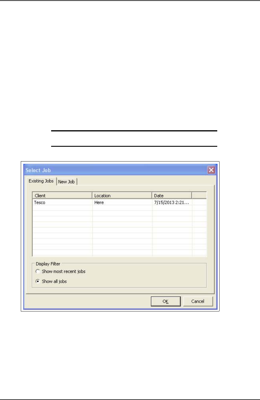
Select Job dialog box
The Select Job dialog box appears after starting TesTORK software. This dialog box enables
the operator to resume work on an existing job, or start a new job.
Two tabs are available in the Select Job dialog box:
• Existing Jobs
•New Job
Existing Jobs
The Existing Jobs tab provides a list of exiting jobs and enables the operator to select a job and
immediately resume work on that job. TesTORK software saves information and connection
data from each job monitored by the software.
Note: If no job is selected, the most recent job is automatically re-
started when the OK button is clicked.
Figure 2-1: Existing Jobs tab
DRAFT VERSION - INTERNAL USE ONLY
SYSTEM OVERVIEW USER GUIDE
CONTACT: 1-877-TESCO-77 WIRELESS TORQUE TURN SYSTEM WWW.TESCOCORP.COM
INTL: 713-359-7295 8 WWW.TESCOPARTS.COM
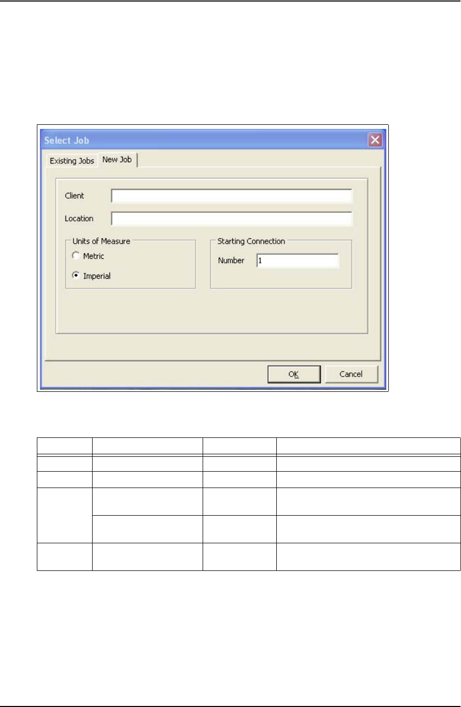
New Job
The New Job tab enables the operator to begin a new job by entering information and
connection data that define the job. Information is first entered in the New Job tab. The Create
New Job dialog box then appears enabling the operator to enter further information and
connection data.
The following items are available in the New Jobs tab:
Figure 2-2: New Job tab
Table 2-1: Create New Job dialog box
Group Item Functionality Description
Client Text box Input of text information
Location Text box Input of text information
Units of
Measure Metric Radio button Configures all data to be displayed in imperial
units
Imperial Radio button Configures all data to be displayed in metric
units
Starting
Connection Number Text box Defines starting connection number
DRAFT VERSION - INTERNAL USE ONLY
USER GUIDE SYSTEM OVERVIEW
CONTACT: 1-877-TESCO-77 WIRELESS TORQUE TURN SYSTEM WWW.TESCOCORP.COM
INTL: 713-359-7295 9 WWW.TESCOPARTS.COM
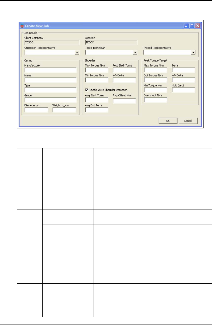
The following items are available in the Create New Job dialog box:
Figure 2-3: Create New Job dialog box
Table 2-2: Create New Job dialog box:
Group Item Functionality Description
Job Details Client Company Text box Displays the name of the company typed in
the New Job tab
Location Text box Displays the name of the location typed in the
New Job tab.
Customer Representative Text box Representative from the customer
Tesco Technician Text box TESCO technician entering the job and
connection data
Thread Representative Text box Independent thread expert
Casing Manufacturer Text box Casing manufacturer
Name Text box Representative from casing manufacturer
Type Text box Type of casing
Grade Text box Steel grade of casing
Diameter cm Text box Casing diameter value. A correct casing
diameter value is vital for accurate calculation
of RPM. A metric or diameter vale can be
entered pending on the units of measure
selection made in the Select Job tab.
For information on selecting how units are
displayed, see Table 2-1 on page 8.
Weight kg/cm Text box Casing weight value. A metric or diameter
vale can be entered pending on the units of
measure selection made in the Select Job tab.
For information on selecting how units are
displayed, see Table 2-1 on page 8.
DRAFT VERSION - INTERNAL USE ONLY

SYSTEM OVERVIEW USER GUIDE
CONTACT: 1-877-TESCO-77 WIRELESS TORQUE TURN SYSTEM WWW.TESCOCORP.COM
INTL: 713-359-7295 10 WWW.TESCOPARTS.COM
Shoulder Test runs are required to determine the number of turns and the shoulder torque value. Use
the Stream Check function. For more information, see
**link to streaming check function
required
.
Max Torque Text box Maximum post-shoulder target range
Min Torque Text box Minimum post-shoulder target range
Post Shldr Turns Text box
The amount the casing should turn after
‘shouldering’ occurs; this value is typically
very low.
+/- Delta Text box
Allowable variance for the post-shoulder
turn.
Avg Start Turns Text box
Sets the turn count that pre-shoulder
averaging begins at
Avg End Turns Text box
Sets the turn count that pre-shoulder
averaging ends at
Avg Offset ft-lb Text box
Sets the shoulder torque value above the
pre-shoulder average
Auto-Shoulder Mode Check box When the auto-shoulder mode is selected the
shoulder point can be moved (manually)
Peak Torque
Target
Consult your casing manufacturer for the information used in this parameter group.
Max Torque ft-lb Text box Maximum allowable torque value. A torque
value above this setting results in a failed
connection result.
Opt Torque ft-lb Text box Optimal torque value
Min Torque ft-lb Text box Minimum allowable torque value. A Torque
value below this setting results in a failed
connection result.
Turns Text box Number of turns required to reach peak torque
+/- Delta Text box Allowable variance in number of turns
required to reach peak torque
Hold (sec) Text box Time required to maintain the optimal torque
setting. During this time, variances outside the
optimal torque range result in a failed
connection result.
Overshoot ft-lb Text box Increased torque value generated by the
momentum of the top drive when the casing
connection is fully tightened
Table 2-2: Create New Job dialog box:
Group Item Functionality Description
DRAFT VERSION - INTERNAL USE ONLY
USER GUIDE SYSTEM OVERVIEW
CONTACT: 1-877-TESCO-77 WIRELESS TORQUE TURN SYSTEM WWW.TESCOCORP.COM
INTL: 713-359-7295 11 WWW.TESCOPARTS.COM
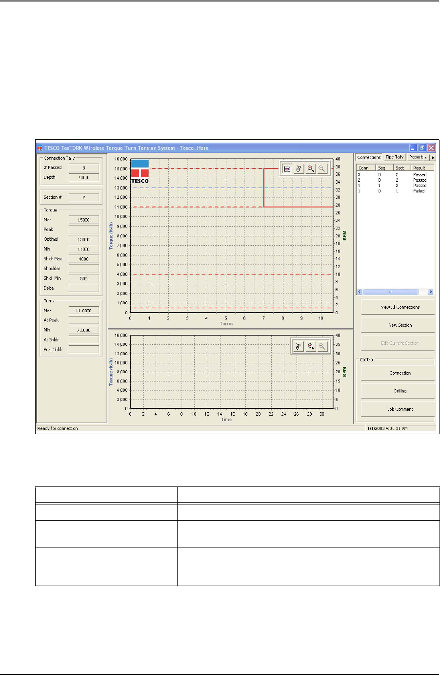
Main screen - **Add section view controls (i.e. panning, zoom-
ing)
The main screen appears after starting TesTORK software and beginning a job. The main
screen provides access to information and dialog boxes that enable the operator to accurately
monitor torque, turns and RPM while making up connections. The main screen also provides
access to data from previous connection attempts, reports and hardware configuration options.
The following items are available from the main screen:
Figure 2-4: Main screen
Table 2-3: Main Screen Interface Elements
Item Data/Notes
Footer bar Contains connection status information
Data fields on the left side of the
screen Displays number of passed connections, depth, torque values, turn
values, shoulder and post-shoulder torque and turn data
Graphs Display torque (and RPM) vs. turns and torque (and RPM) vs. time
Information is displayed in real time as the connection progresses.
DRAFT VERSION - INTERNAL USE ONLY

SYSTEM OVERVIEW USER GUIDE
CONTACT: 1-877-TESCO-77 WIRELESS TORQUE TURN SYSTEM WWW.TESCOCORP.COM
INTL: 713-359-7295 12 WWW.TESCOPARTS.COM
Data fields on left Side of Screen
The following data is available on the left side of the screen:
Connections button Provides access to the following dialog boxes:
•View All Connections
•New Section
• Edit Current Section
• Connection
• Drilling
• Job Comment
Pipe Tally
tab Enables the operator to view a list of all connection attempts
Reports
tab Enables the operator to view and print data section and connection
data
Hardware
tab Enables the operator to view hardware configuration information.
Administrators are able to access and configure the System Settings
dialog box
About WTTS
tab Enables the operator to view
TesTORK software version information
Table 2-4: Data fields on left side of screen
Group Item Description
Connection
Tally # Passed Number of connections categorized as being passed
Depth Current total depth of casing
Section # Every change to job
information and connection data creates a
new section number
Torque Max Value entered in Create New Job or Add New Section dialog box
Peak Peak torque value during a connection attempt
Optimal Value entered in Create New Job or Add New Section dialog box
Min Value entered in Create New Job or Add New Section dialog box
Shldr Max Value entered in Create New Job or Add New Section dialog box
Shoulder System or manually defined value
Shldr Min Value entered in Create New Job or Add New Section dialog box
Delta Value entered in Create New Job or Add New Section dialog box
TurnsMax Value entered in Create New Job or Add New Section dialog box
At Peak How many turns taken to reach the peak torque value during a
connection attempt
Min Value entered in Create New Job or Add New Section dialog box
At Shldr How many turns taken to reach the shoulder value during a
connection attempt. System or manually defined value
Post Shldr Value entered in Create New Job or Add New Section dialog box
Table 2-3: Main Screen Interface Elements
Item Data/Notes
DRAFT VERSION - INTERNAL USE ONLY
USER GUIDE SYSTEM OVERVIEW
CONTACT: 1-877-TESCO-77 WIRELESS TORQUE TURN SYSTEM WWW.TESCOCORP.COM
INTL: 713-359-7295 13 WWW.TESCOPARTS.COM
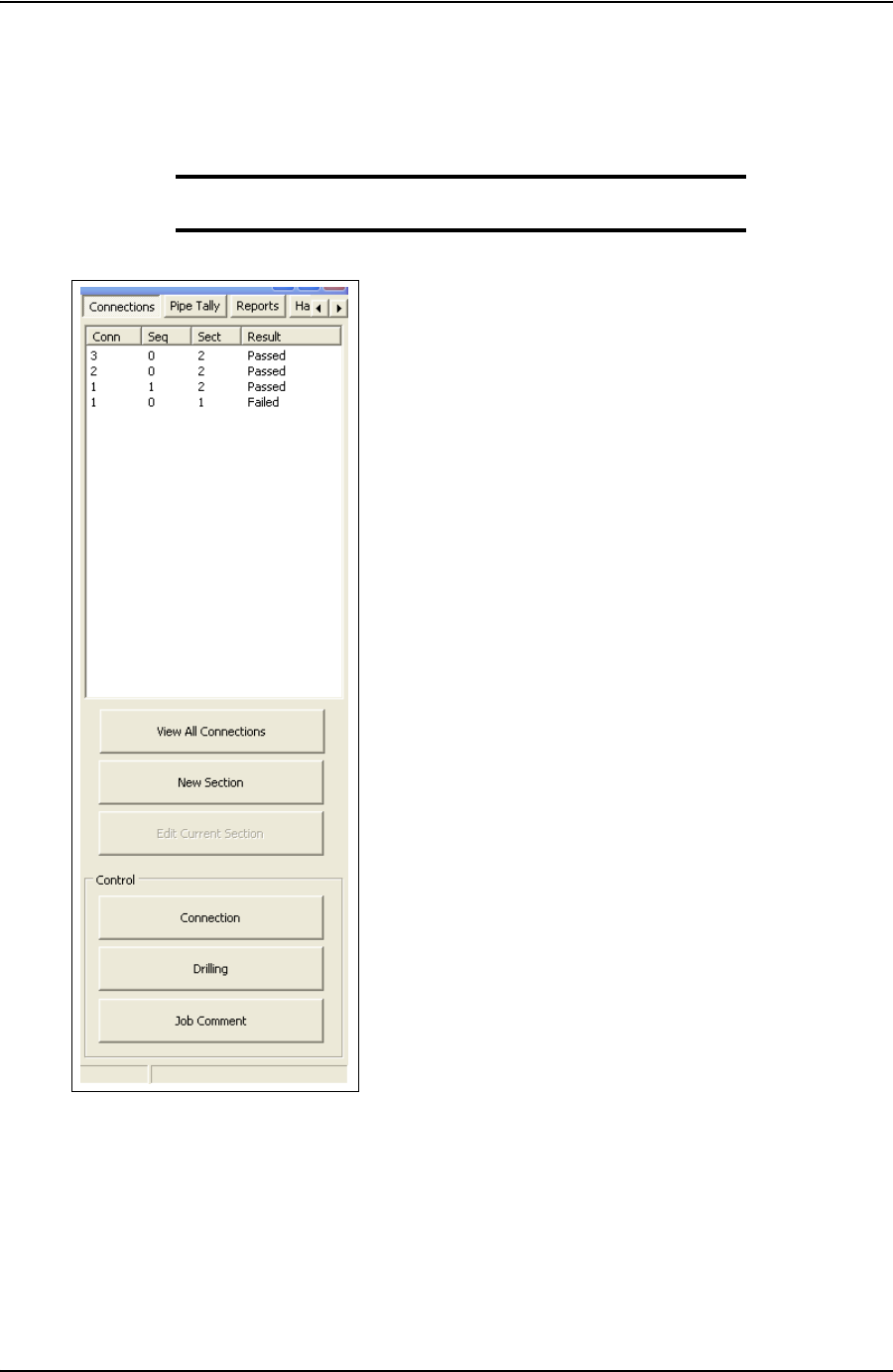
Connections Side Panel
The Connections side panel enables the operator to access the following dialog boxes and
windows:
Note: A list of the results from each attempted connection is also
displayed when the Connections button is clicked.
View All Connections
Clicking the View All Connections button enables the operator to access the View Connections
window containing details of all casing connections made as part of the current job. The View
Connections window also features buttons that enable the operator View Graph, View Section
and Remove Conn (remove connection).
Figure 2-5: Connections side panel
DRAFT VERSION - INTERNAL USE ONLY
SYSTEM OVERVIEW USER GUIDE
CONTACT: 1-877-TESCO-77 WIRELESS TORQUE TURN SYSTEM WWW.TESCOCORP.COM
INTL: 713-359-7295 14 WWW.TESCOPARTS.COM
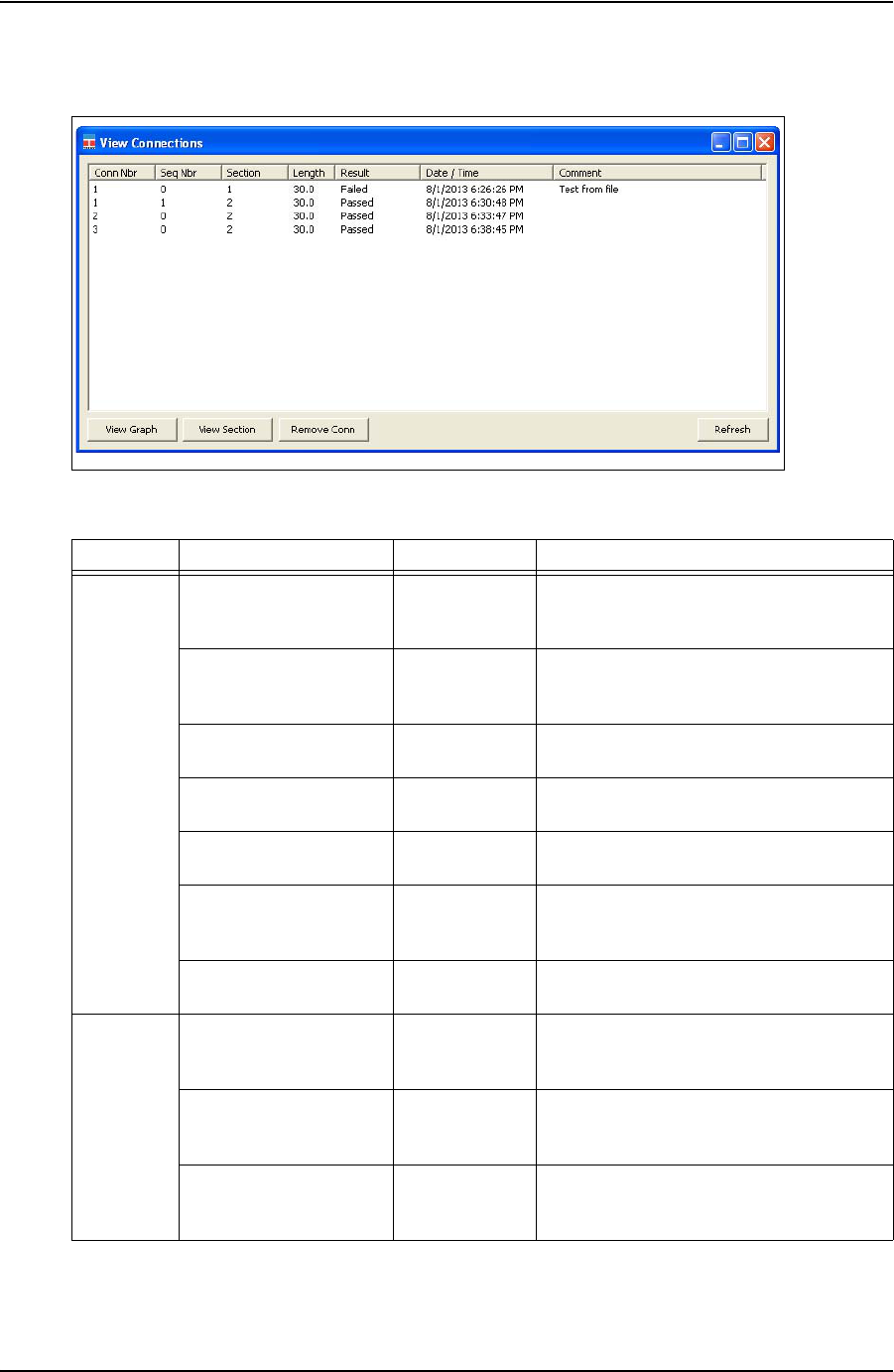
Figure 2-6: View Connections Window
Table 2-5: View Connections Window:
Group Item Functionality Description
Columns Conn Nbr
(Connection Number) Displays the
connection
number
Running total of connections made
Seq Number
(Sequence Number) Displays the
sequence
number
Number of attempts made on a connection
Section Displays the
SectionSection number
Length Displays casing
length Length of casing used in connection
Result Display
connection result Can be a passed, failed or forced pass
connection
Date/Time Displays time
and date
information
Displays the exact time and date of each
connection attempt
Comments Displays
Comments The operator can enter comments
Button View Graph Displays the
graph of the
selected item.
Displays the graphed connection data from
the selected connection attempt
View Section Displays job
information and
connection data.
Displays the job information and connection
data for the selected connection attempt
Remove Conn
(remove connection) Removes the last
connection
attempt
Removes the last connection attempt from a
job
DRAFT VERSION - INTERNAL USE ONLY
USER GUIDE SYSTEM OVERVIEW
CONTACT: 1-877-TESCO-77 WIRELESS TORQUE TURN SYSTEM WWW.TESCOCORP.COM
INTL: 713-359-7295 15 WWW.TESCOPARTS.COM
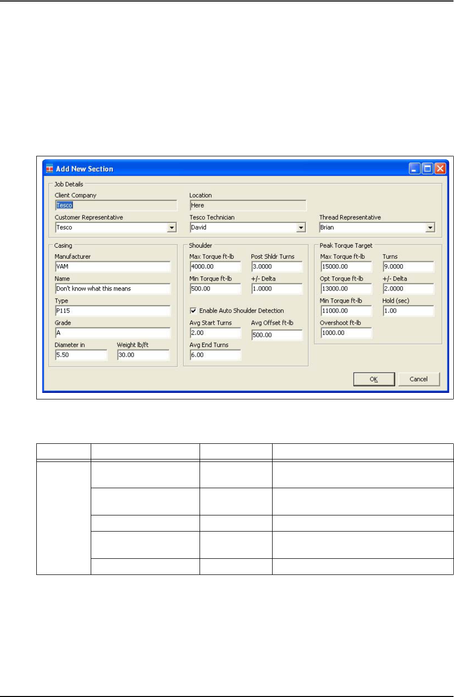
Add New Section
The Add New Section window enables the operator to make revisions to the job details and
connection data. A new section is created each time a change is made to the job details and
connection data following a connection attempt.
However, changes can be made to the job details and connection data without creating a new
section if a connection has not yet been attempted.
Figure 2-7: Add New Section Window
Table 2-6: Add New Section Window:
Group Item Functionality Description
Job Details Client Company Text box Displays the name of the company typed in
the New Job tab
Location Text box Displays the name of the location typed in the
New Job tab.
Customer Representative Text box Representative from the customer
Tesco Technician Text box TESCO technician entering the job and
connection data
Thread Representative Text box Independent thread expert
DRAFT VERSION - INTERNAL USE ONLY

SYSTEM OVERVIEW USER GUIDE
CONTACT: 1-877-TESCO-77 WIRELESS TORQUE TURN SYSTEM WWW.TESCOCORP.COM
INTL: 713-359-7295 16 WWW.TESCOPARTS.COM
Casing Manufacturer Text box Casing manufacturer
Name Text box Representative from casing manufacturer
Type Text box Type of casing
Grade Text box Steel grade of casing
Diameter cm Text box Casing diameter value. A correct casing
diameter value is vital for accurate calculation
of RPM. A metric or diameter vale can be
entered pending on the units of measure
selection made in the Select Job tab.
For information on selecting how units are
displayed, see Table 2-1 on page 8.
Weight kg/cm Text box Casing weight value. A metric or diameter
vale can be entered pending on the units of
measure selection made in the Select Job tab.
For information on selecting how units are
displayed, see Table 2-1 on page 8.
Shoulder Test runs are required to determine the number of turns and the shoulder torque value. Use
the Stream Check function. For more information.
Max Torque Text box Maximum post-shoulder target range
Min Torque Text box Minimum post-shoulder target range
Post Shldr Turns Text box
The amount the casing should turn after
‘shouldering’ occurs; this value is typically
very low.
+/- Delta Text box
Allowable variance for the post-shoulder
turn.
Avg Start Turns Text box
Sets the turn count that pre-shoulder
averaging begins at
Avg End Turns Text box
Sets the turn count that pre-shoulder
averaging ends at
Avg Offset ft-lb Text box
Sets the shoulder torque value above the
pre-shoulder average
Auto-Shoulder Mode Check box When the auto-shoulder mode is selected the
shoulder point can be moved (manually)
Peak Torque
Target
Consult your casing manufacturer for the information used in this parameter group.
Max Torque ft-lb Text box Maximum allowable torque value. A torque
value above this setting results in a failed
connection result.
Opt Torque ft-lb Text box Optimal torque value
Min Torque ft-lb Text box Minimum allowable torque value. A Torque
value below this setting results in a failed
connection result.
Turns Text box Number of turns required to reach peak torque
Table 2-6: Add New Section Window:
Group Item Functionality Description
DRAFT VERSION - INTERNAL USE ONLY

USER GUIDE SYSTEM OVERVIEW
CONTACT: 1-877-TESCO-77 WIRELESS TORQUE TURN SYSTEM WWW.TESCOCORP.COM
INTL: 713-359-7295 17 WWW.TESCOPARTS.COM
Edit Current Selection
Enables the operator to makes changes to a current section’s job information and connection
data if no connection attempt has yet been made within that section. If a connection attempt
has been made, the button is not functional.
+/- Delta Text box Allowable variance in number of turns
required to reach peak torque
Hold (sec) Text box Time required to maintain the optimal torque
setting. During this time, variances outside the
optimal torque range result in a failed
connection result.
Overshoot ft-lb Text box Increased torque value generated by the
momentum of the top drive when the casing
connection is fully tightened
Table 2-6: Add New Section Window:
Group Item Functionality Description
DRAFT VERSION - INTERNAL USE ONLY
SYSTEM OVERVIEW USER GUIDE
CONTACT: 1-877-TESCO-77 WIRELESS TORQUE TURN SYSTEM WWW.TESCOCORP.COM
INTL: 713-359-7295 18 WWW.TESCOPARTS.COM
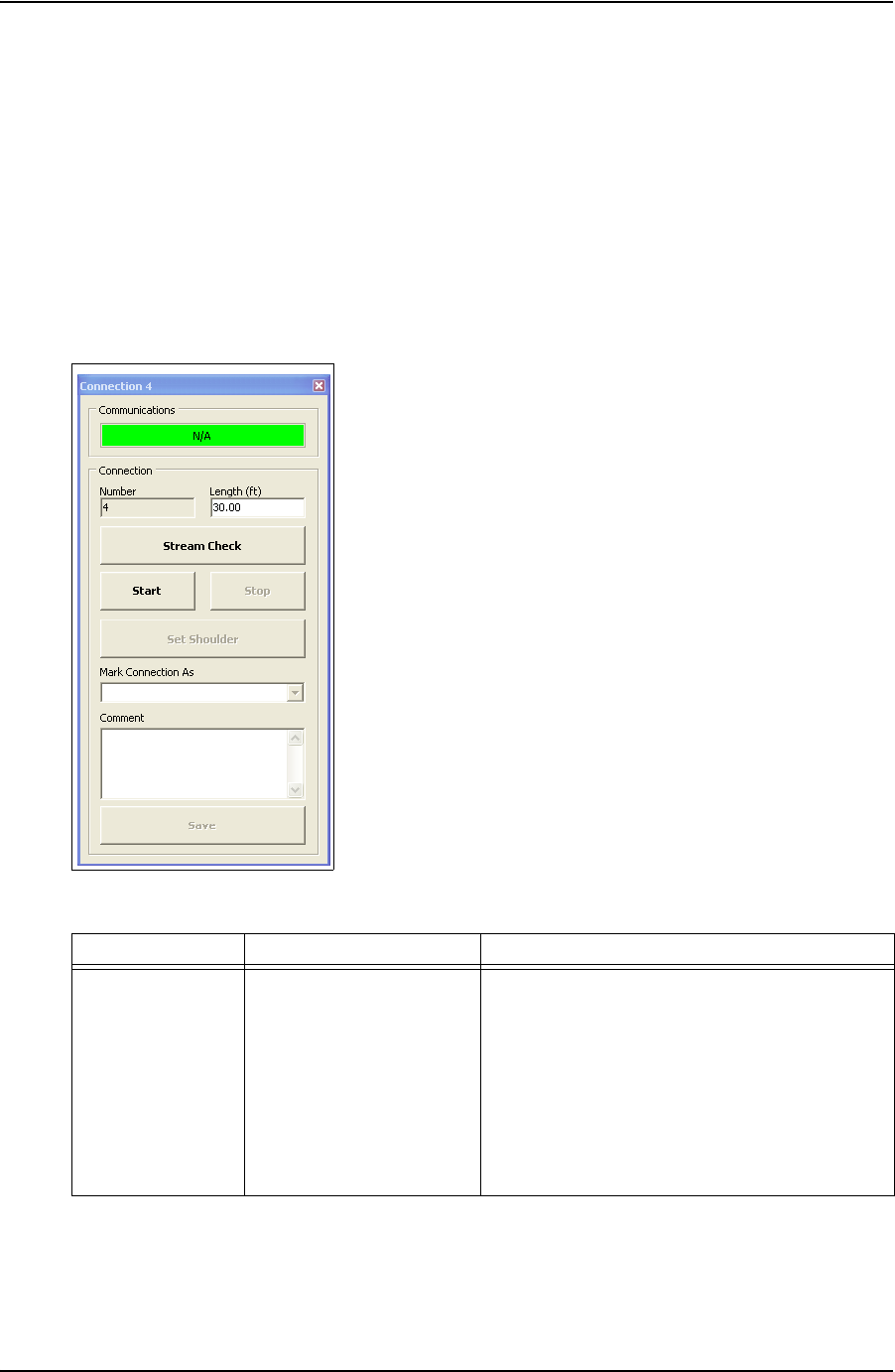
Connection
The Connection dialog box enables the operator to begin monitoring a connection attempt.
Once a connection attempt is complete, the Connection dialog box displays the connection
result pass or fail. The operator can accept the connection result or assigned a Forced Pass
designation to a connection attempt that failed.
The Connection dialog box also enables the operator to start a streaming checking and monitor
connection data without logging the data. The operator can also add comments associated wit
each connection attempt and edit casing length data.
Figure 2-8: Connection Window
Table 2-7: Connection Window Dialog
Group Field/Element Name Data/Notes
Communications Status Bar Provides information on the connection status
between the TesTORK and TesTORK Manager
software. The following connection status messages
can be displayed:
•Hunting - No connection between the TesTORK
and TesTORK Manager software
•Idle - Connection is established between the Tes-
TORK and TesTORK Manager software
•Streaming - TesTORK Manager software is reiev-
ing connection data from the TesTORK
DRAFT VERSION - INTERNAL USE ONLY
USER GUIDE SYSTEM OVERVIEW
CONTACT: 1-877-TESCO-77 WIRELESS TORQUE TURN SYSTEM WWW.TESCOCORP.COM
INTL: 713-359-7295 19 WWW.TESCOPARTS.COM
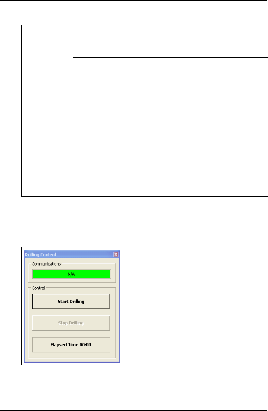
Drilling
The Drilling Control dialog box enables the operator to view torque and turns data without the
data being logged. Data is updated every second rather than at 100 times a second.
Connection Number Increments with every passed or forced pass
connection. Remains the same for a failed connection
attempt.
Length (ft) Length of current casing (not including thread)
Stream Check
Displays connection data without logging the data.
Start Starts logging a connection attempt. Once the casing
has completed two turns, logging cannot be aborted
and the result is recorded.
Stop Stops logging the connection attempt once complete
and returns connection status to Idle status.
Set Shoulder Enables the operator to manually set a shoulder point.
If TesTORK Manager software doesn’t automatically
detect a shoulder, this button is set by default.
Mark Connection As Enables the operator to record a connection attempt
as a Pass, Failed or Forced Passed. A comment must
be added if a connection result is over ridden or the
connection attempt failed.
Comment Enables the operator to add a comment to any
connection attempt. However, comments must be
added to a Failed or Forced Passed. attempt.
Figure 2-9: Drilling Control Window
Table 2-7: Connection Window Dialog (Continued)
Group Field/Element Name Data/Notes
DRAFT VERSION - INTERNAL USE ONLY
SYSTEM OVERVIEW USER GUIDE
CONTACT: 1-877-TESCO-77 WIRELESS TORQUE TURN SYSTEM WWW.TESCOCORP.COM
INTL: 713-359-7295 20 WWW.TESCOPARTS.COM
Table 2-8: Drilling Control Window Dialog
Group Field/Element Name Data/Notes
Communications Status Bar Provides information on the connection status
between the TesTORK and TesTORK Manager
software. The following connection status messages
can be displayed:
•Hunting - No connection between the TesTORK
and TesTORK Manager software
•Idle - Connection is established between the Tes-
TORK and TesTORK Manager software
Streaming - TesTORK Manager software is reieving
connection data from the TesTORK
Control Start Drilling Starts displaying torque and turns data
Stop Drilling Returns TesTORK Manager software to Idle mode
Elapsed Time Time since the Start button was pressed
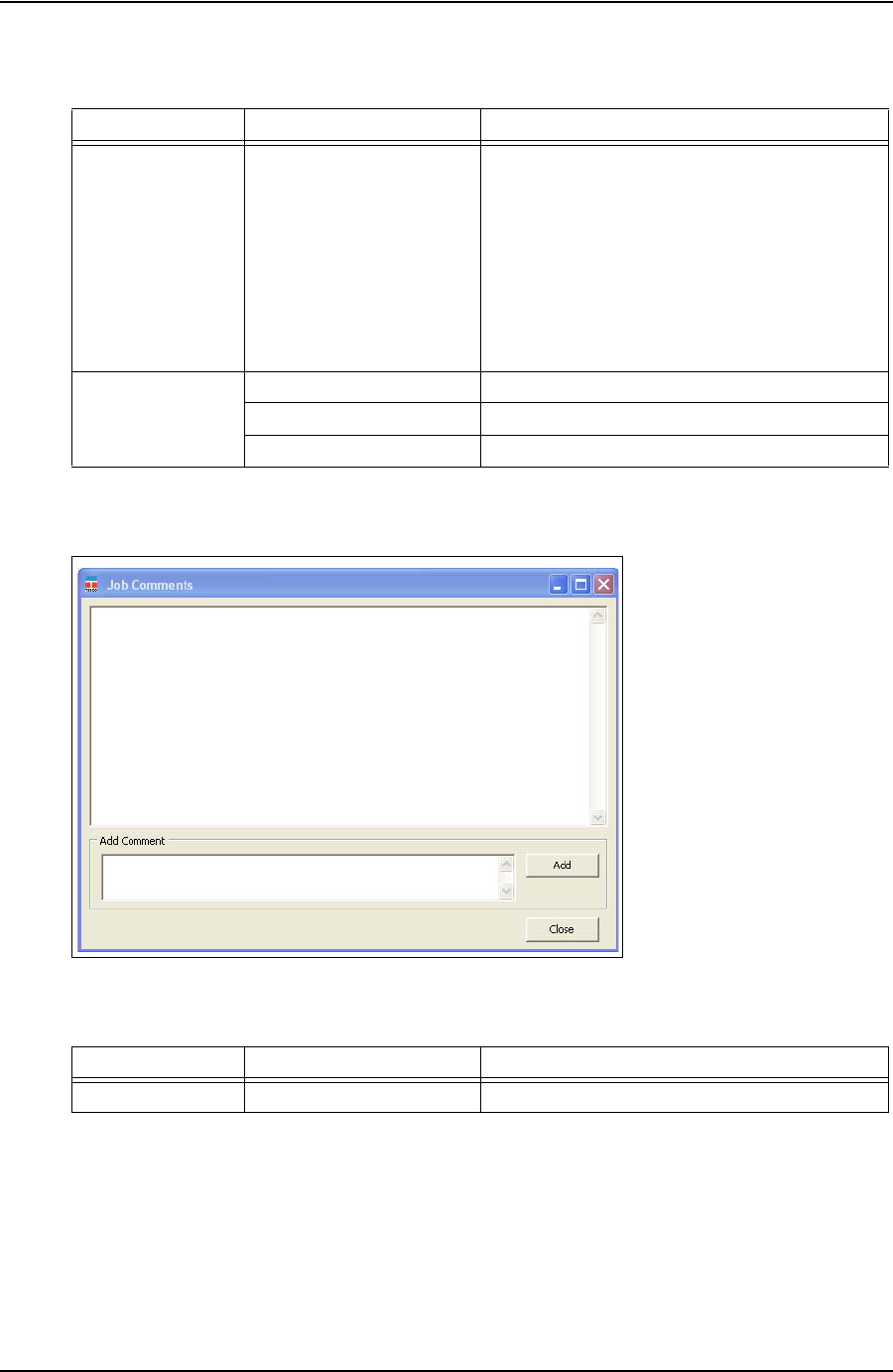
Figure 2-10: Job Comments Window
Table 2-9: Job Comments Dialog
Group Field/Element Name Data/Notes
Add Comment Enables the operator to add comments about a job
DRAFT VERSION - INTERNAL USE ONLY
USER GUIDE SYSTEM OVERVIEW
CONTACT: 1-877-TESCO-77 WIRELESS TORQUE TURN SYSTEM WWW.TESCOCORP.COM
INTL: 713-359-7295 21 WWW.TESCOPARTS.COM
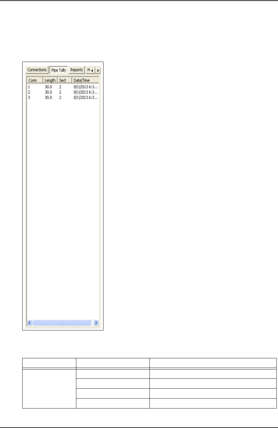
Pipe Tally Side Panel
The Pipe Tally side panel displays a list of all connection attempts. When a connection attempt
is selected the connection data associated with the attempt is displayed:
Figure 2-11: Pipe Tally Window
Table 2-10: Pipe Tally Dialog
Group Field/Element Name Data/Notes
Pipe Tally Conn (Connection) Connection number
Length Casing length
Sect (Section) Section number
Date/Time Time and date connection attempt was started
DRAFT VERSION - INTERNAL USE ONLY
SYSTEM OVERVIEW USER GUIDE
CONTACT: 1-877-TESCO-77 WIRELESS TORQUE TURN SYSTEM WWW.TESCOCORP.COM
INTL: 713-359-7295 22 WWW.TESCOPARTS.COM
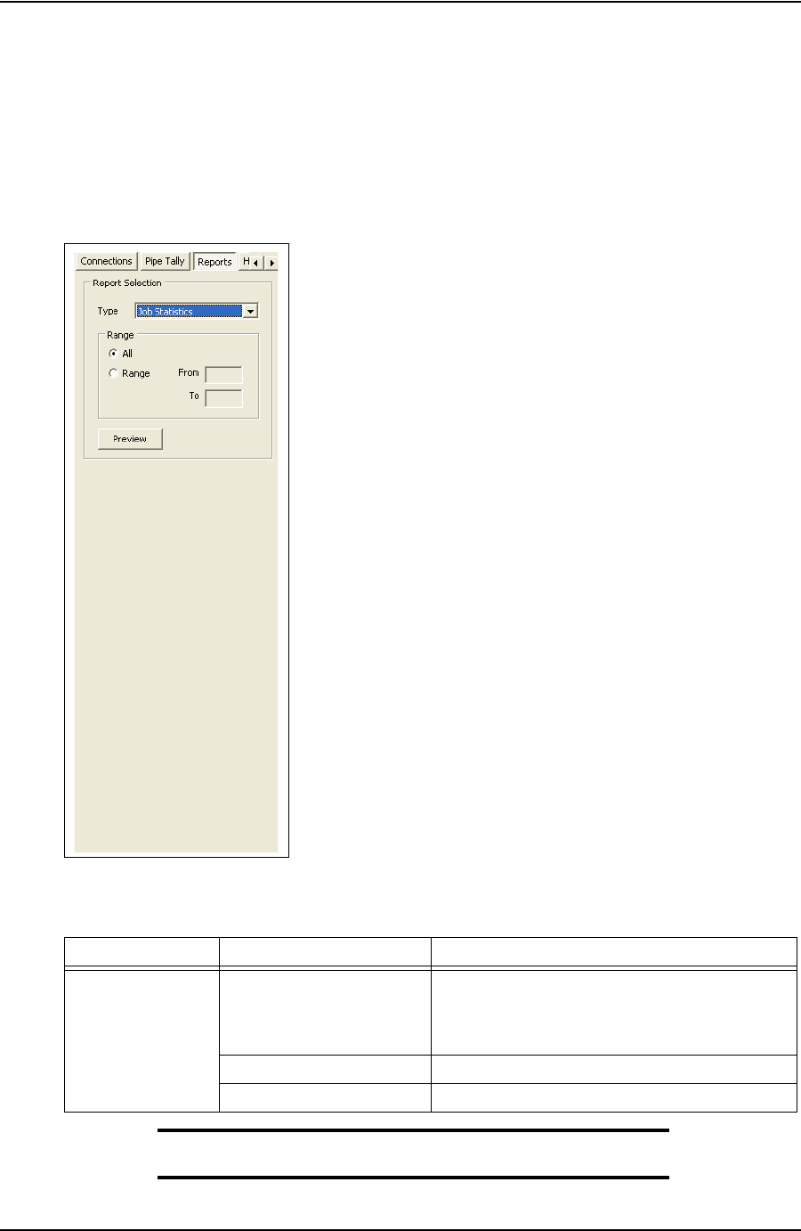
Reports Side Panel
The Reports side panel displays the Report Selection window By selecting from the drop down
menu, an operator can view accumulated data from a job. Data includes job statistics, individ-
ual section details, combined section details and job comments.
Note: For a complete description of each report and the informa-
tion available, see “Generating Reports” on page 51.
Figure 2-12: Reports Window
Table 2-11: Reports Window Dialog
Group Field/Element Name Data/Notes
Report Selection Type
(Drop Down Menu) Job Statistics
Sections (detail)
Sections (summary)
Connections
Range (All or Range)Display all items or a range of items
Preview (Button) Displays report
DRAFT VERSION - INTERNAL USE ONLY
USER GUIDE SYSTEM OVERVIEW
CONTACT: 1-877-TESCO-77 WIRELESS TORQUE TURN SYSTEM WWW.TESCOCORP.COM
INTL: 713-359-7295 23 WWW.TESCOPARTS.COM
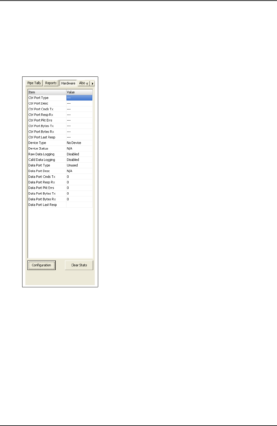
Hardware Side Panel
The Hardware side panel displays information about the Wireless Torque Turn Tension Sys-
tem.
Figure 2-13: Hardware Window
DRAFT VERSION - INTERNAL USE ONLY

SYSTEM OVERVIEW USER GUIDE
CONTACT: 1-877-TESCO-77 WIRELESS TORQUE TURN SYSTEM WWW.TESCOCORP.COM
INTL: 713-359-7295 24 WWW.TESCOPARTS.COM
Table 2-12: Hardware Window Dialog
Group Field/Element Name Data/Notes
Item Ctrl Port Type
(Control Port Type) System information
Ctrl Port Desc
(Control Port Description) System information
Ctrl Port Cmds Tx System information
Ctrl Port Resp Rx System information
Ctrl Port Pkt Errs System information
Ctrl Port Bytes Tx System information
Ctrl Port Bytes Rx System information
Ctrl Port Last Resp System information
Device Type System information
Device Status System information - Status is Idle when
communication is established between the
TesTORKand TesTORK Manager software
Raw Data Logging System information
Cal’d Data Logging System information
Data Port Type System information
Data Port Desc System information
Data Port Cmds Tx System information
Data Port Resp Rx System information
Data Port Pkt Errs System information
Data Port Bytes Tx System information
Data Port Bytes Rx System information
Data Port Last Resp System information
Buttons Configuration Enables access to the TesTork System Settings
dialog box. A password is required. For more
information on using the TesTork System Settings
dialog box, see “” on page 70.
Clear Stats **Please supply description
DRAFT VERSION - INTERNAL USE ONLY
USER GUIDE SYSTEM OVERVIEW
CONTACT: 1-877-TESCO-77 WIRELESS TORQUE TURN SYSTEM WWW.TESCOCORP.COM
INTL: 713-359-7295 25 WWW.TESCOPARTS.COM
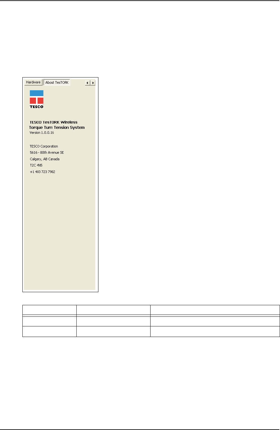
About WTTTS side panel
The About WTTTS side panel displays the TESCO Wireless Torque Turn Tension System
(WTTTS) Version as well as TESCO contact information.
Figure 2-14: About WTTTS Window
Table 2-13: About WTTTS Dialog Box
Group Field/Element Name Data/Notes
About WTTTS Version The Current Software Version of the TESCO WTTTS.
Contact Information TESCO Corporation Contact Information
DRAFT VERSION - INTERNAL USE ONLY

SYSTEM OVERVIEW USER GUIDE
CONTACT: 1-877-TESCO-77 WIRELESS TORQUE TURN SYSTEM WWW.TESCOCORP.COM
INTL: 713-359-7295 26 WWW.TESCOPARTS.COM
DRAFT VERSION - INTERNAL USE ONLY

USER GUIDE
CONTACT: 1-877-TESCO-77 WIRELESS TORQUE TURN SYSTEM WWW.TESCOCORP.COM
INTL: 713-359-7295 27 WWW.TESCOPARTS.COM
C
HAPTER
3: I
NSTALLATION
AND
S
TART
UP
This chapter provides information on installing and starting The TesTORK Wireless Torque /
Turn Monitoring System‘s hardware and software components.
The installation process consists of the following general procedures:
• Pre-installation activities
Note: Once a job has been defined, the TesTORK system com-
ponents must be inspected and verified before going to the job
site.
• Pre-job component inspection
• On-site rig-up procedures
• Installing the Torque Sub
• System start-up
P
RE
-I
NSTALLATION
A
CTIVITIES
Verify Casing Data
Before traveling to the casing running job site, ensure the following information about the cas-
ing has been collected from the field supervisors at TESCO (see Pre-Job Information checklist
881031 in “Appendix B: TTS Checklists and Forms”).
• casing weight
• casing size
• approximate lengths (tally sheet)
• connection types
Pre-Job Component Inspection
Complete the following steps to ensure that the TesTORK system is complete and functional
before traveling to the job site.
1. Ensure that all TesTORK components are present in the pelican case(s).
2. Check all cables for wear or damaged ends. If damage is detected, or if a cable is
suspect, pin out the cord and verify its condition.
DRAFT VERSION - INTERNAL USE ONLY

INSTALLATION AND START UP USER GUIDE
CONTACT: 1-877-TESCO-77 WIRELESS TORQUE TURN SYSTEM WWW.TESCOCORP.COM
INTL: 713-359-7295 28 WWW.TESCOPARTS.COM
3. Connect the system together and verify that data is being received at the computer
and most importantly check the battery life. If battery life is not enough to complete
the job, install new lithium D size batteries before going to site.
Note: See “Appendix A: Changing The Battery” for more informa-
tion.
4. After completing the initial system verification and confirming that all the required
components are present, repack all of the items into the pelican case(s) and crate.
5. Submit the completed checklist to the supervisor to confirm that there is a complete
kit prepared for the upcoming job.
6. Use form 881027 as a reference; see “Appendix B: TTS Checklists and Forms”
Pre-job system test
Ensure a pre-job system test is completed (i.e. communication can be established between the
TesTORK and TesTORK Manager software) before traveling to the job site.
For example:
1. Connect all equipment.
2. Switch on computer
3. Ensure connection has been established between the TesTORK and TesTORK
Manager software
DRAFT VERSION - INTERNAL USE ONLY
USER GUIDE INSTALLATION AND START UP
CONTACT: 1-877-TESCO-77 WIRELESS TORQUE TURN SYSTEM WWW.TESCOCORP.COM
INTL: 713-359-7295 29 WWW.TESCOPARTS.COM
O
N
-S
ITE
R
IG
U
P
P
ROCEDURES
Complete the following steps to ensure that the correct placement of the TesTORK system’s
hardware devices after arriving at the job site.
1. Report to the on-site supervisor(s) for orientation and initial introductions.
2. Install the TesTORK sub.
Note: For more information on installing the TesTORK sub, see “
Installing the TesTORK sub”.
3. Go to the rig floor and determine suitable locations for the following TesTORK
system devices:
Danger! Ensure each TesTORK system device is located
in a position appropriate to the device’s
hazardous location rating. For information on
TesTORK system device hazardous location
ratings, see “Appendix D: Device Hazardous
Location Ratings”.
Danger! A printer (and USB flash drive if used) must only
be used in a safe area. For information on using
these items, refer to the manufacturer’s
instructions and safety data supplied with each
device.
• Computer
• Base radio
Caution: The base radio must be positioned with its antenna in line
of sight with the TesTORK.
• Printer and USB flash drive (optional equipment not supplied by TESCO)
4. Place the TesTORK system devices.
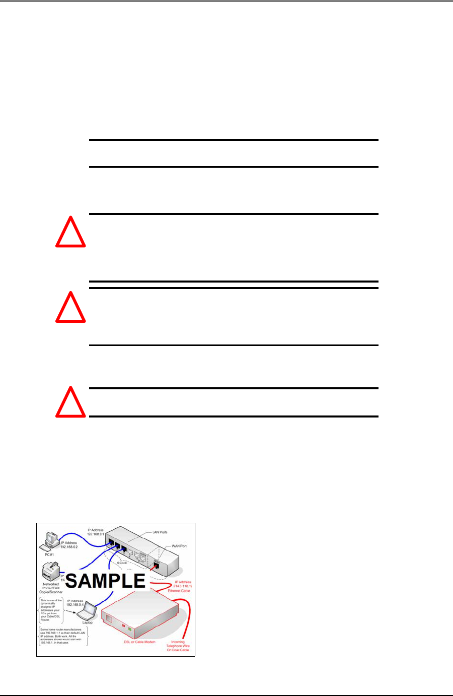
5. Connect the TesTORK system devices as shown in following network diagram:
*The following is a sample network diagram of the type to be added - Talk to Brian
Figure 3-1: TesTORK system device network diagram
!
!
!
DRAFT VERSION - INTERNAL USE ONLY

INSTALLATION AND START UP USER GUIDE
CONTACT: 1-877-TESCO-77 WIRELESS TORQUE TURN SYSTEM WWW.TESCOCORP.COM
INTL: 713-359-7295 30 WWW.TESCOPARTS.COM
I
NSTALLING
THE
T
ES
TORK
SUB
Content or cross reference TBD
DRAFT VERSION - INTERNAL USE ONLY

USER GUIDE INSTALLATION AND START UP
CONTACT: 1-877-TESCO-77 WIRELESS TORQUE TURN SYSTEM WWW.TESCOCORP.COM
INTL: 713-359-7295 31 WWW.TESCOPARTS.COM
S
YSTEM
S
TART
U
P
After the on-site rig up procedures have been completed and the TesTORK has been installed,
the TesTORK system is ready to start.
Once started, the TesTORK system is ready to begin monitoring and logging connection
attempts.
Note: For information on using TesTORK system to monitor and
log connection attempts, see “Using TesTORK Manager Soft-
ware” on page 37.
Start the TesTORK system by completing the following procedures:
1. Turn on the TesTORK
2. Start TesTORK Manager software
Turning the TesTORK on or off
When the TesTORK is turned on it will automatically start looking for a wireless signal from
base radio. The TesTORK automatically connects to the base radio (and TesTORK Manager
software) once a connections is established.
Note: The TesTORK sub is automatically powered off when it
does not have a wireless connection for 15 minutes or more.
Therefore, when not in use for an extended period on the rig, dis-
connect power to the receiver to preserve the batteries in the Tes-
TORK.
DRAFT VERSION - INTERNAL USE ONLY
INSTALLATION AND START UP USER GUIDE
CONTACT: 1-877-TESCO-77 WIRELESS TORQUE TURN SYSTEM WWW.TESCOCORP.COM
INTL: 713-359-7295 32 WWW.TESCOPARTS.COM
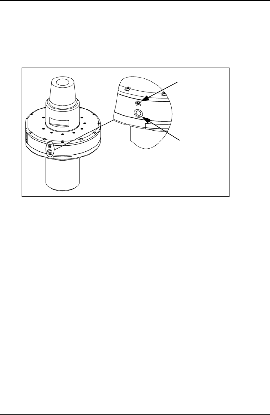
Use the following procedures to turn the TesTORK sub on or off:
To turn on the TesTORK sub
Push the Power button on the side of the TesTORK sub.
The light tube located above the power button will flash five times
To turn off the TesTORK sub
Push the Power button on the side of the TesTORK sub.
The power button will flash five times.
Figure 3-2: Turning on the TesTORK
On button
Light tube
DRAFT VERSION - INTERNAL USE ONLY

USER GUIDE INSTALLATION AND START UP
CONTACT: 1-877-TESCO-77 WIRELESS TORQUE TURN SYSTEM WWW.TESCOCORP.COM
INTL: 713-359-7295 33 WWW.TESCOPARTS.COM
Starting TesTORK Manager software
Use the following procedures to start TesTORK Manager software and check that connection
has been established between the TesTORK sub and TesTORK Manager software.
To start TesTORK Manager software
1. Ensure the computer hosting TesTORK Manager software is powered up and the
desktop is displayed on the screen.
2. Double-click the TestTORKManager program icon located on the Desktop.
The Select Job dialog box appears.
Note: If this is the first time starting TesTORK Manager software
on the host computer, a dialog box appears confirming that a job
directory must be set before starting the software. Browse to and
select (create) a suitable folder, and then click OK.
TesTORK Manager software uses the selected folder to store log files
containing configuration and connection data from each job started in the
software.
3. Select one of the following options:
If you want to: Complete these steps:
Start an existing job
a. Ensure the Existing Jobs tab is selected.
The Existing Jobs dialog box appears.
b. Select a job, and then click OK.
Note: Use the Display Filter buttons to display the most recent jobs
or all jobs.
The TesTORK Manager software main screen appears.
DRAFT VERSION - INTERNAL USE ONLY
INSTALLATION AND START UP USER GUIDE
CONTACT: 1-877-TESCO-77 WIRELESS TORQUE TURN SYSTEM WWW.TESCOCORP.COM
INTL: 713-359-7295 34 WWW.TESCOPARTS.COM
To check connection between the TesTORK sub and TesTORK Manager software
1. On the main screen, click the Connections button.
The Connections dialog box appears.
2. Check the Communications status box
Create a new job
a. Click the New Jobs tab.
The New Jobs dialog box appears.
b. Type a client name in the Client box.
c. Type a location in the Location box.
d. Select a unit of measure using the Units of Measure radio buttons.
e. Type a starting connection number in the Starting Connection box.
f. Click OK.
The Create New Job Window appears
g. Type the relevant information or data in the text boxes.
Note: For a description of each text box item, see Figure 2-3 on
page 9.
h. Click OK.
The TesTORK Manager software main screen appears.
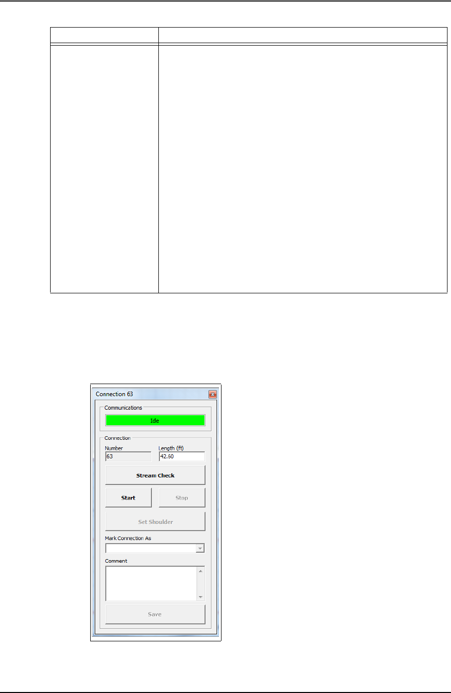
Figure 3-3: Connections dialog box
If you want to: Complete these steps:
DRAFT VERSION - INTERNAL USE ONLY

USER GUIDE INSTALLATION AND START UP
CONTACT: 1-877-TESCO-77 WIRELESS TORQUE TURN SYSTEM WWW.TESCOCORP.COM
INTL: 713-359-7295 35 WWW.TESCOPARTS.COM
The message Idle is displayed when communication between the TesTORK and
TesTORK Manager software is established.
DRAFT VERSION - INTERNAL USE ONLY

INSTALLATION AND START UP USER GUIDE
CONTACT: 1-877-TESCO-77 WIRELESS TORQUE TURN SYSTEM WWW.TESCOCORP.COM
INTL: 713-359-7295 36 WWW.TESCOPARTS.COM
DRAFT VERSION - INTERNAL USE ONLY

USER GUIDE
CONTACT: 1-877-TESCO-77 WIRELESS TORQUE TURN SYSTEM WWW.TESCOCORP.COM
INTL: 713-359-7295 37 WWW.TESCOPARTS.COM
C
HAPTER
4: U
SING
T
ES
TORK M
ANAGER
S
OFTWARE
*This chapter requires more work and information adding
This chapter provides information on using the TesTORK Wireless Torque / Turn Monitoring
System to monitor and log connection attempts.
The information provided in this chapter is organized into the following sections:
• Pre-job activity list
• About the TesTORK Manager Software Main Window
• Viewing and logging connection data
P
RE
-
JOB
A
CTIVITY
L
IST
Ensure the following activities have been completed before beginning a job and using the pro-
cedures in this chapter.
Note: For more information on checking the connectivity between
the TesTORK sub and TesTORK Manager software, see “To
check connection between the TesTORK sub and TesTORK Man-
ager software” on page 34.
Table 1: Pre-job task list
Activity Reference
Pre-installation activities
page 27
On-site rig-up procedures
page 29
Installation of the TesTORK sub
page 30
System Start-up
page 31
Ensuring a connection has been established between the TesTORK sub and
TesTORK Manager software.
page 34
DRAFT VERSION - INTERNAL USE ONLY
USING TESTORK MANAGER SOFTWARE USER GUIDE
CONTACT: 1-877-TESCO-77 WIRELESS TORQUE TURN SYSTEM WWW.TESCOCORP.COM
INTL: 713-359-7295 38 WWW.TESCOPARTS.COM
A
BOUT
THE
T
ES
TORK M
ANAGER
S
OFTWARE
M
AIN
W
INDOW
The TesTORK system’s operational features and functionality are accessed by clicking buttons
at the top right side of the TesTORK Manager software’s main window. As each button is
clicked, the panel on the right side of the screen changes enabling access to the operational
features associated with each button.
The following operational features are available by clicking the buttons at the top right side of
the screen.
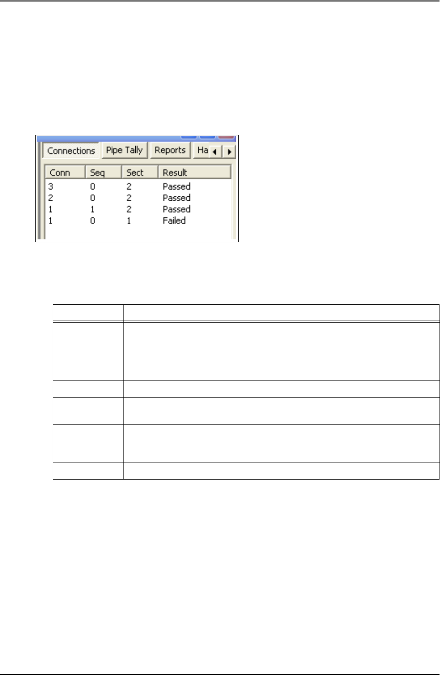
Figure 4-1: Feature buttons
Table 2: Operational features
Button Enables the operator to:
Connections • View information on completed connections
• Add a new section by updating the connection configuration data
•Log a connection attempt
• Monitoring a drilling operation
• Add a job comment
Pipe Tally View a list of connections
Reports View and print reports providing information job statistics, sections, connections and
job comments
Hardware View system data. The Hardware panel side panel also enables access to the
administrator settings. A password is required to access these settings. For more
information, see See “Accessing the System Settings Dialog Box” on page 56.
About TesTORK View
TesTORK Manager software version information
DRAFT VERSION - INTERNAL USE ONLY

USER GUIDE USING TESTORK MANAGER SOFTWARE
CONTACT: 1-877-TESCO-77 WIRELESS TORQUE TURN SYSTEM WWW.TESCOCORP.COM
INTL: 713-359-7295 39 WWW.TESCOPARTS.COM
V
IEWING
AND
L
OGGING
C
ONNECTION
D
ATA
The Connections side panel provides access to all TesTORK Manager software features asso-
ciated with logging a connection attempt.
Click the Connections button to access the following features:
Table 3: Pre-job task list
Side panel Use this feature to: Reference
Connection
• Log a passed connection
• Log a failed connection
• Force past a failed connection
Drilling
Continually monitor torque and RPM at the at
the top drive during a drilling operation
Job Comment
Add a comment about the job
View All Connections
View information on each connection attempt
for the current job.
The following Information is available:
• Graphs showing the connection attempt
data
• Configuration data used for each connec-
tion attempt
New Section
Begin a new section by changing the job
details or connection configuration data.
Edit Current Section
Edit a new section before a connection
attempt has been made
DRAFT VERSION - INTERNAL USE ONLY

USING TESTORK MANAGER SOFTWARE USER GUIDE
CONTACT: 1-877-TESCO-77 WIRELESS TORQUE TURN SYSTEM WWW.TESCOCORP.COM
INTL: 713-359-7295 40 WWW.TESCOPARTS.COM
Logging a Connection Attempt
This section explains how to use TesTORK Manager software to view and log connection
attempts.
Note: Ensure the steps in the “Pre-Job Activity List” have been
completed before using the procedures in this chapter. For more
information, see See “Pre-job Activity List” on page 37.
The following procedures are explained in this chapter:
Log a Passed Connection
Use the following procedure to accept the Passed status assigned to a connection by TesTORK
Manager software and continue to the next connection.
Note: The recorded status of a connection attempt assigned a
“Passed” status cannot be changed once the connection attempt
has been saved.
1. On the main screen, click the Connections button.
Table 4: Viewing and logging connection attempt options
Procedure Description
Log a passed connection Use TesTORK Manager software to log a successful connection
attempt.
Log a failed connection Use TesTORK Manager software to log an unsuccessful
connection attempt.
Force past a failed connection It is possible to force a Pass status on a failed connection if the
operator has determined that the connection is correct, but
TesTORK Manager software has not recognized it as such.
One situation in which a failed connection might be forced is
when the threaded coupling on the top of the casing has been
removed. This can cause faults to occur. Torquing two
connections at once can create a fault alarm as the shoulders
might not synchronize and the applied/registered torque might be
more erratic than what was set as parameters for Fail status. In
this case, it is permitted to force a Pass status if the correct end
result torque is achieved. The comment section allows comments
regarding the reason for the pass; comments are required for all
force failed or force passed connections. In addition, the option to
increase the connection number to account for the double joint is
available.
Another situation where a force pass connection might occur is if
the operator clicks the Start button after the casing has already
turned a number times. This will produce a fault that indicates
shouldering occurred too early and/or the optimum torque was
achieved within too few turns. If it is confirmed that the connection
is actually correct, then force pass the connection.
DRAFT VERSION - INTERNAL USE ONLY

USER GUIDE USING TESTORK MANAGER SOFTWARE
CONTACT: 1-877-TESCO-77 WIRELESS TORQUE TURN SYSTEM WWW.TESCOCORP.COM
INTL: 713-359-7295 41 WWW.TESCOPARTS.COM
The Connections dialog box appears.
Note: Change the casing length if required.
Note: The connection number is automatically assigned the next
number in the sequence.
Note: Click Stream Check to display connection data without
logging a connection attempt or determining a shoulder point.
To close the Connections dialog box after performing a stream
check, click Stream Check.
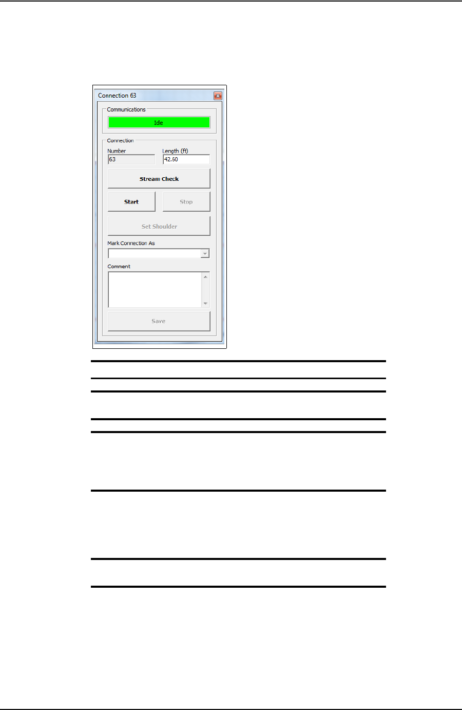
2. Click Start.
TesTORK Manager software is now ready to begin logging and displaying con-
nection data.
Note: No data is displayed until the top drive operator begins a
connection attempt.
3. Start a connection attempt.
Figure 4-2: Connections dialog box
DRAFT VERSION - INTERNAL USE ONLY
USING TESTORK MANAGER SOFTWARE USER GUIDE
CONTACT: 1-877-TESCO-77 WIRELESS TORQUE TURN SYSTEM WWW.TESCOCORP.COM
INTL: 713-359-7295 42 WWW.TESCOPARTS.COM
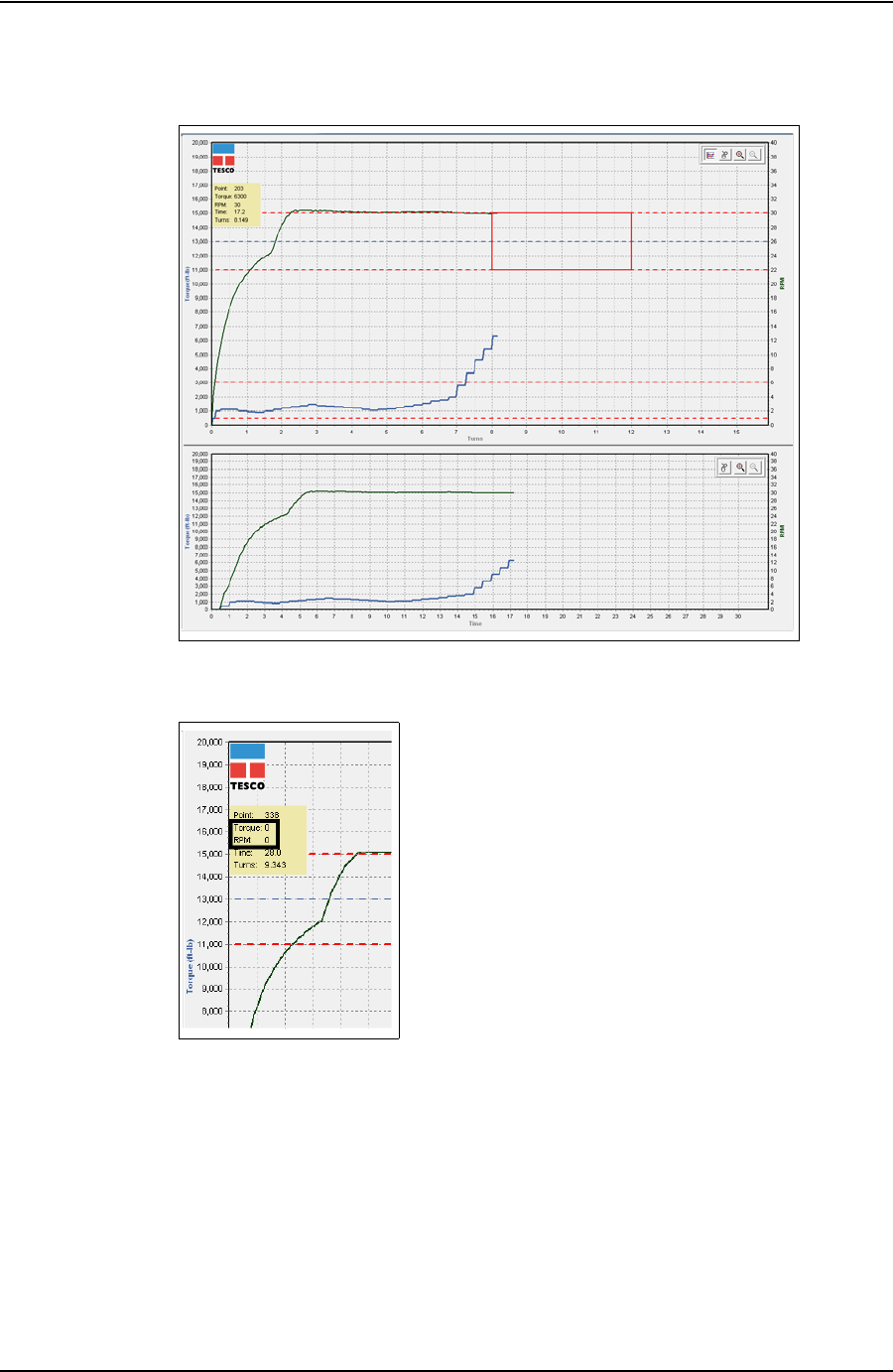
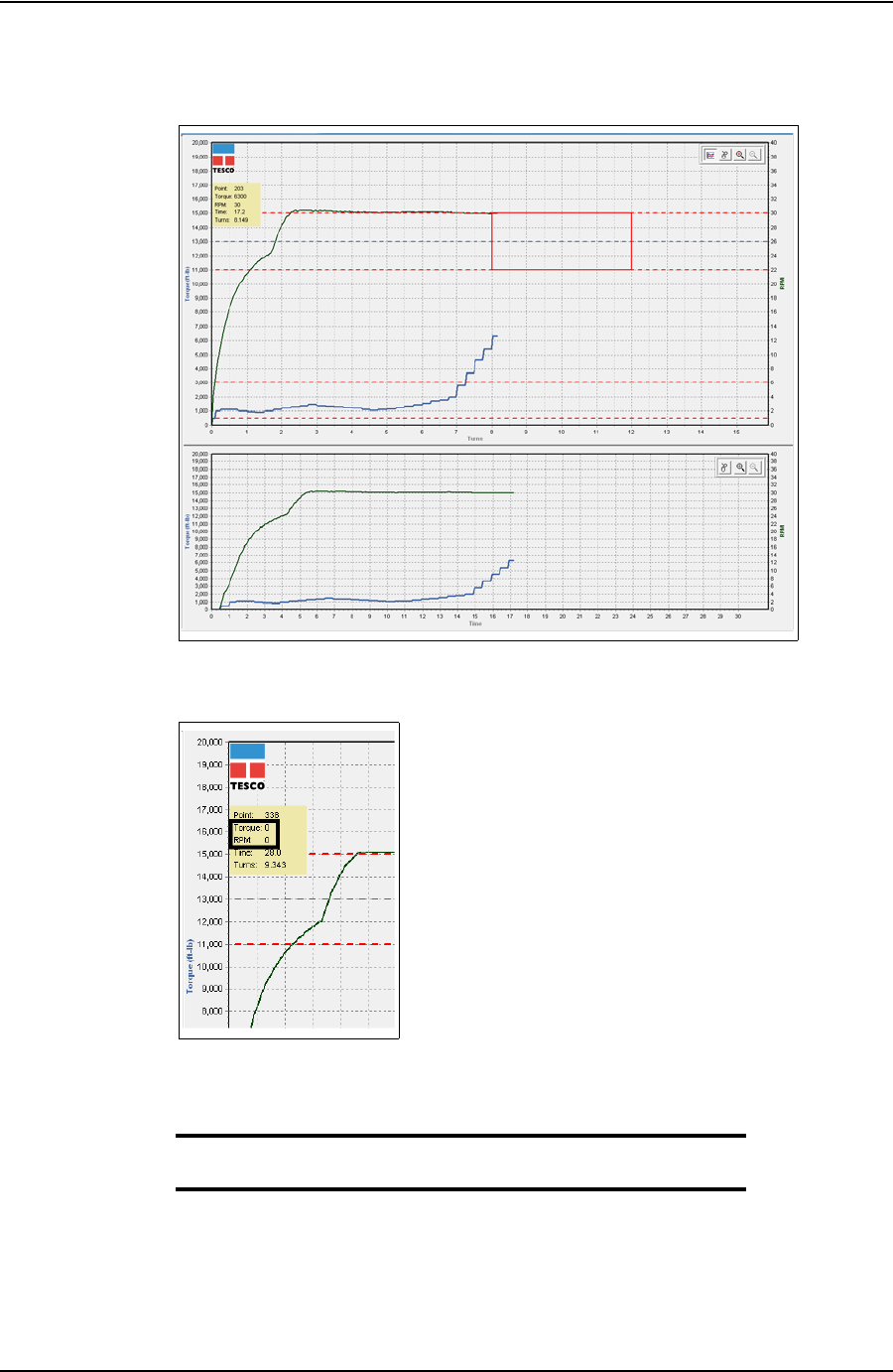
TesTORK Manager software begins logging and displaying connection data.
4. When the Torque and RPM values reach zero, click Stop.
5. Type comments in the Comment text box, if required.
6. Click Save.
The connection number and length are added to the running totals and the connec-
tion data is logged.
Log a Failed Connection
Use the following procedure to accept the Failed status assigned to a connection by the system
and continue to the next connection.
Figure 4-3: Connection data
Figure 4-4: Torque and RPM values
DRAFT VERSION - INTERNAL USE ONLY
USER GUIDE USING TESTORK MANAGER SOFTWARE
CONTACT: 1-877-TESCO-77 WIRELESS TORQUE TURN SYSTEM WWW.TESCOCORP.COM
INTL: 713-359-7295 43 WWW.TESCOPARTS.COM
1. On the main screen, click the Connections button.
The Connections dialog box appears.
Note: Change the casing length if required.
Note: The connection number is automatically assigned the next
number in the sequence.
Note: Click Stream Check to display connection data without
logging a connection attempt or determining a shoulder point.
To close the Connections dialog box after performing a stream
check, click Stream Check.
2. Click Start.
TesTORK Manager software is now ready to begin logging and displaying con-
nection data.
Note: No data is displayed until the top drive operator begins a
connection attempt.
3. Start a connection attempt.
Figure 4-5: Connections dialog box
DRAFT VERSION - INTERNAL USE ONLY
USING TESTORK MANAGER SOFTWARE USER GUIDE
CONTACT: 1-877-TESCO-77 WIRELESS TORQUE TURN SYSTEM WWW.TESCOCORP.COM
INTL: 713-359-7295 44 WWW.TESCOPARTS.COM
TesTORK Manager software begins logging and displaying connection data.
4. When the Torque and RPM values reach zero, click Stop.
Failed is displayed in the Mark Connection drop-down list.
5. Type comments in the Comment text box.
Note: A comment must be typed in the Comment text box before
clicking Save.
6. Click Save.
The connection number and length are added to the running totals and the connec-
tion data is logged.
Figure 4-6: Connection data
Figure 4-7: Torque and RPM
DRAFT VERSION - INTERNAL USE ONLY
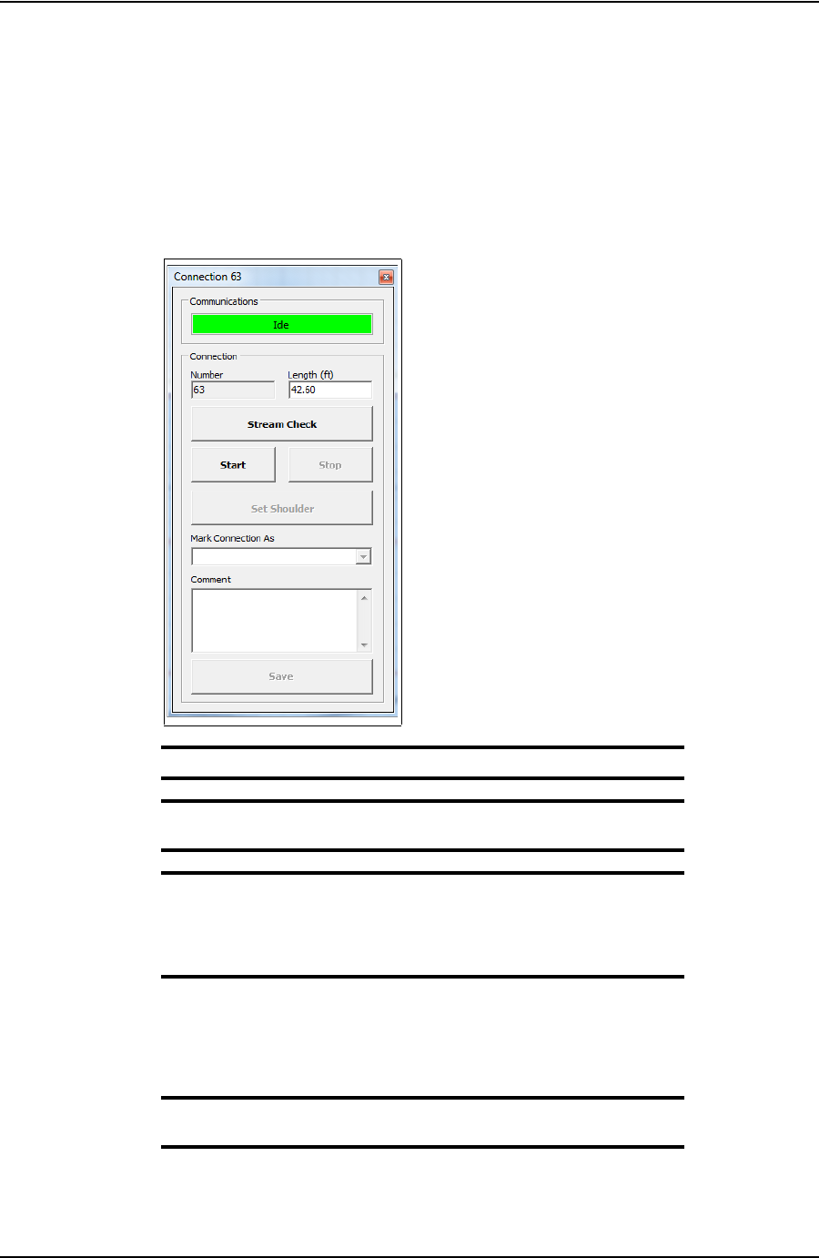
USER GUIDE USING TESTORK MANAGER SOFTWARE
CONTACT: 1-877-TESCO-77 WIRELESS TORQUE TURN SYSTEM WWW.TESCOCORP.COM
INTL: 713-359-7295 45 WWW.TESCOPARTS.COM
Force Past a Failed Connection
Use the following procedure to assign a Force Past result to a connection attempt assigned a
Failed status by the system, and continue to the next connection.
1. On the main screen, click the Connections button.
The Connections dialog box appears.
Note: Change the casing length if required.
Note: The connection number is automatically assigned the next
number in the sequence.
Note: Click Stream Check to display connection data without
logging a connection attempt or determining a shoulder point.
To close the Connections dialog box after performing a stream
check, click Stream Check.
2. Click Start.
TesTORK Manager software is now ready to begin logging and displaying con-
nection data.
Note: No data is displayed until the top drive operator begins a
connection attempt.
3. Start a connection attempt.
Figure 4-8: Connections dialog box
DRAFT VERSION - INTERNAL USE ONLY
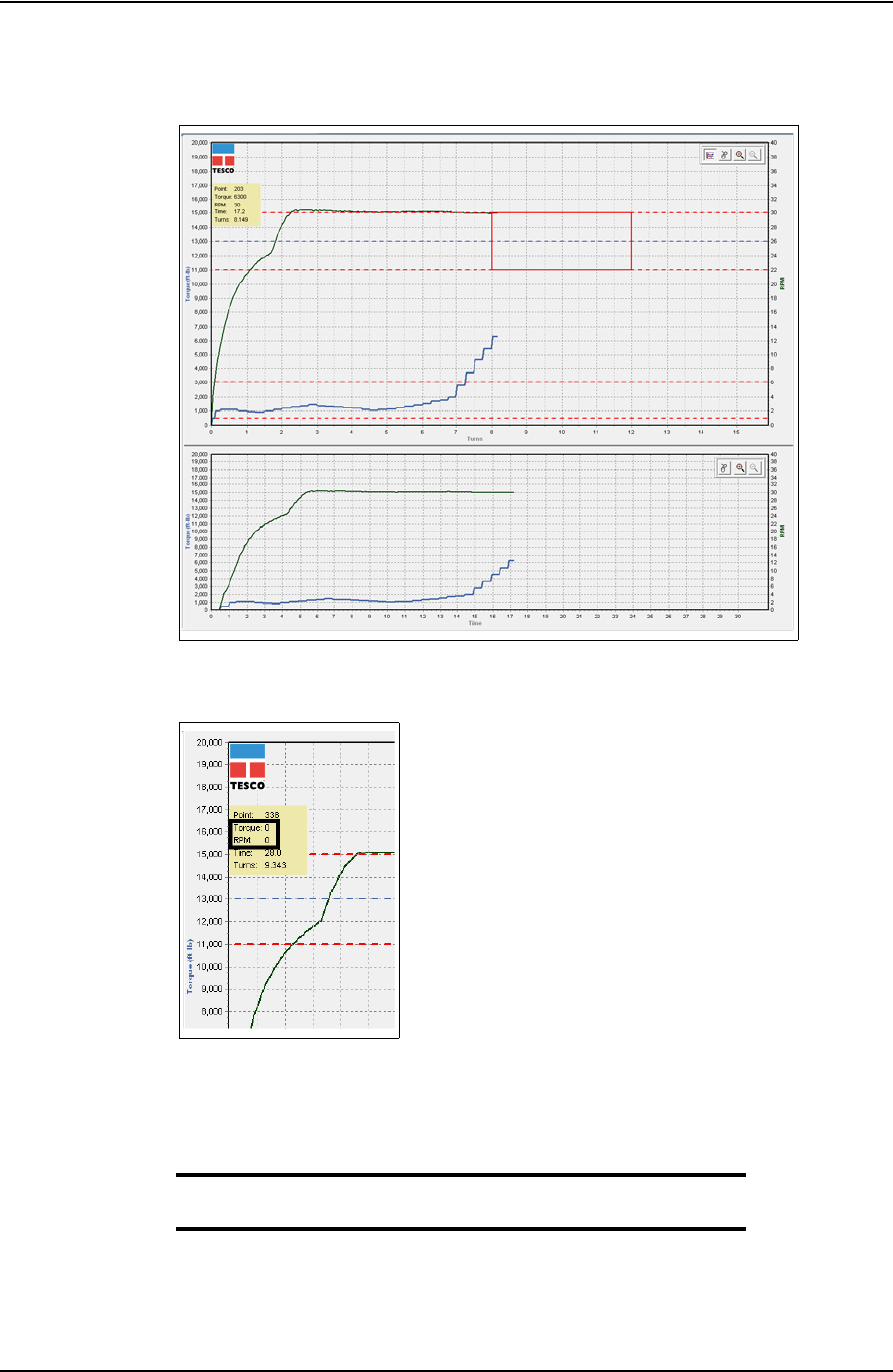
USING TESTORK MANAGER SOFTWARE USER GUIDE
CONTACT: 1-877-TESCO-77 WIRELESS TORQUE TURN SYSTEM WWW.TESCOCORP.COM
INTL: 713-359-7295 46 WWW.TESCOPARTS.COM
TesTORK Manager software begins logging and displaying connection data.
4. When the Torque and RPM values reach zero, click Stop.
Failed is displayed in the Mark Connection drop-down list.
5. Select Forced Pass from the Mark Connection drop-down list.
6. Type comments in the Comment text box.
Note: A comment must be typed in the Comment text box before
clicking Save.
7. Click Save.
The connection number and length are added to the running totals and the connec-
tion data is logged.
Figure 4-9: Connection data
Figure 4-10: Torque and RPM
DRAFT VERSION - INTERNAL USE ONLY

USER GUIDE USING TESTORK MANAGER SOFTWARE
CONTACT: 1-877-TESCO-77 WIRELESS TORQUE TURN SYSTEM WWW.TESCOCORP.COM
INTL: 713-359-7295 47 WWW.TESCOPARTS.COM
Performing a Manual Shoulder Operation
**The wording in this section requires checking and amending
TesTORK Manager software enables the operator to manually change the shoulder point if the
software doesn’t detect a shoulder during a connection attempt.
The program then recalculates the delta turn and delta torque from the new shoulder point val-
ues.
When a new job folder is created, the shoulder detection method automatically defaults to
Auto Shoulder Detection mode.
Note:
In Auto Mode, everything works the same as previously described. If the shoulder detection
method needs to be changed to MANUAL, then the operator must go to the Connection dialog
box and select manual shoulder.
Note: Notice the Shoulder Target values have been disabled and
the Shoulder Target Mode has been changed to Manual Shoul-
der. The Main Screen also indicates that Manual Shoulder mode
has been selected.
Note: Selecting Manual Shoulder disables alarms associated
with automatic shouldering.
To manually set the shoulder point
**Needs finishing
Use the following procedure to manually set the shoulder point.
1. On the main screen, click the Connections button.
DRAFT VERSION - INTERNAL USE ONLY
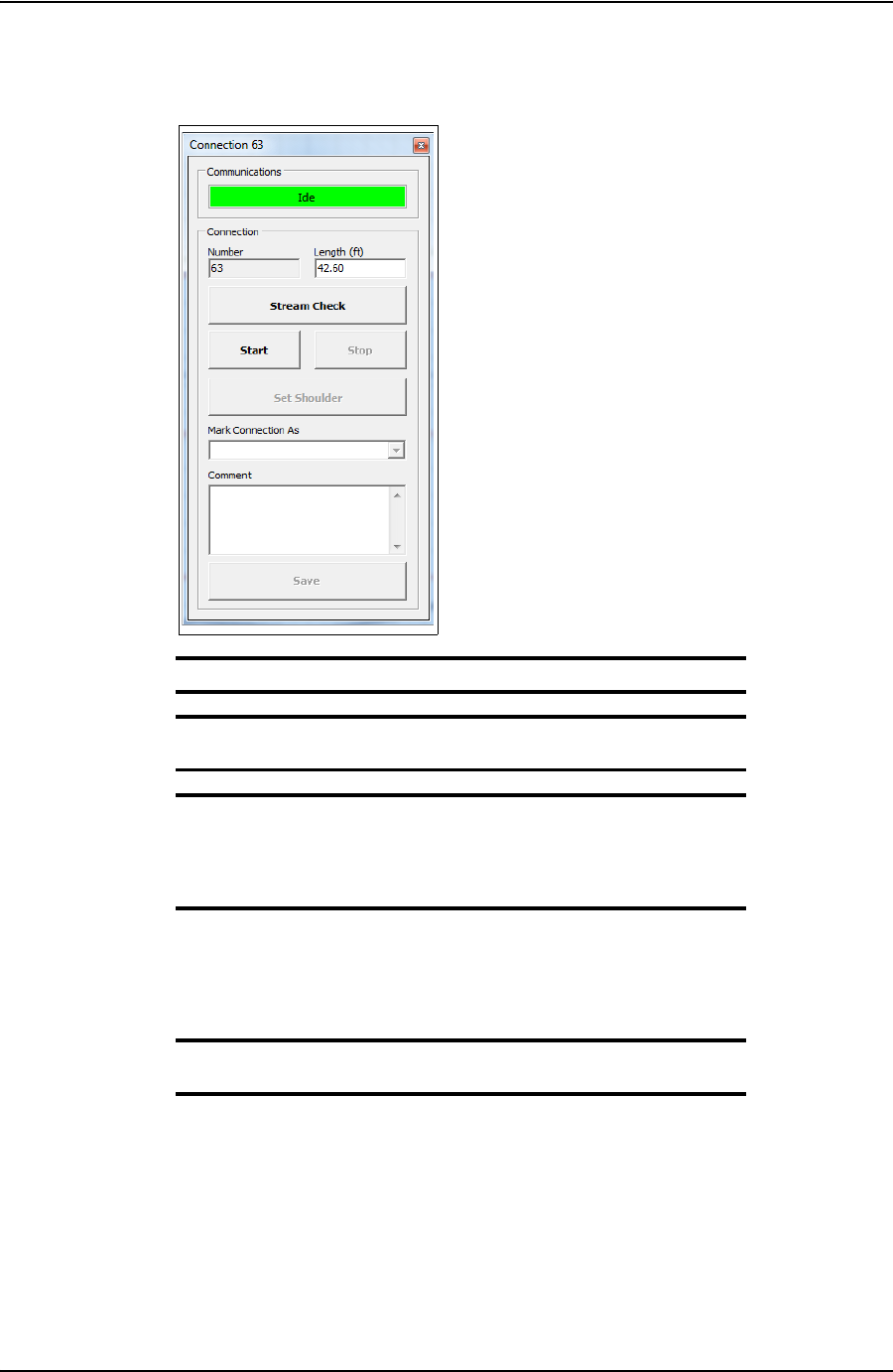
USING TESTORK MANAGER SOFTWARE USER GUIDE
CONTACT: 1-877-TESCO-77 WIRELESS TORQUE TURN SYSTEM WWW.TESCOCORP.COM
INTL: 713-359-7295 48 WWW.TESCOPARTS.COM
The Connections dialog box appears.
Note: Change the casing length if required.
Note: The connection number is automatically assigned the next
number in the sequence.
Note: Click Stream Check to display connection data without
logging a connection attempt or determining a shoulder point.
To close the Connections dialog box after performing a stream
check, click Stream Check.
2. Click Start.
TesTORK Manager software is now ready to begin logging and displaying con-
nection data.
Note: No data is displayed until the top drive operator begins a
connection attempt.
3. Start a connection attempt.
This content requires adding: On the connection dialog box click “Set Shoul-
der”. This message is displayed if the software doesn’t find a shoulder it auto
click “Set Shoulder”
Figure 4-11: Connections dialog box
DRAFT VERSION - INTERNAL USE ONLY

USER GUIDE USING TESTORK MANAGER SOFTWARE
CONTACT: 1-877-TESCO-77 WIRELESS TORQUE TURN SYSTEM WWW.TESCOCORP.COM
INTL: 713-359-7295 49 WWW.TESCOPARTS.COM
Using the Drilling Control Feature
**Content required for this section
Adding a Job Comment
**Content required for this section
DRAFT VERSION - INTERNAL USE ONLY

USING TESTORK MANAGER SOFTWARE USER GUIDE
CONTACT: 1-877-TESCO-77 WIRELESS TORQUE TURN SYSTEM WWW.TESCOCORP.COM
INTL: 713-359-7295 50 WWW.TESCOPARTS.COM
V
IEWING
P
IPE
T
ALLY
D
ATA
Clicking the Pipe Tally button enables the operator to view information and data on each con-
nection attempt completed during the current job.
*This section requires more information adding and the procedures to generate reports
documenting.
DRAFT VERSION - INTERNAL USE ONLY
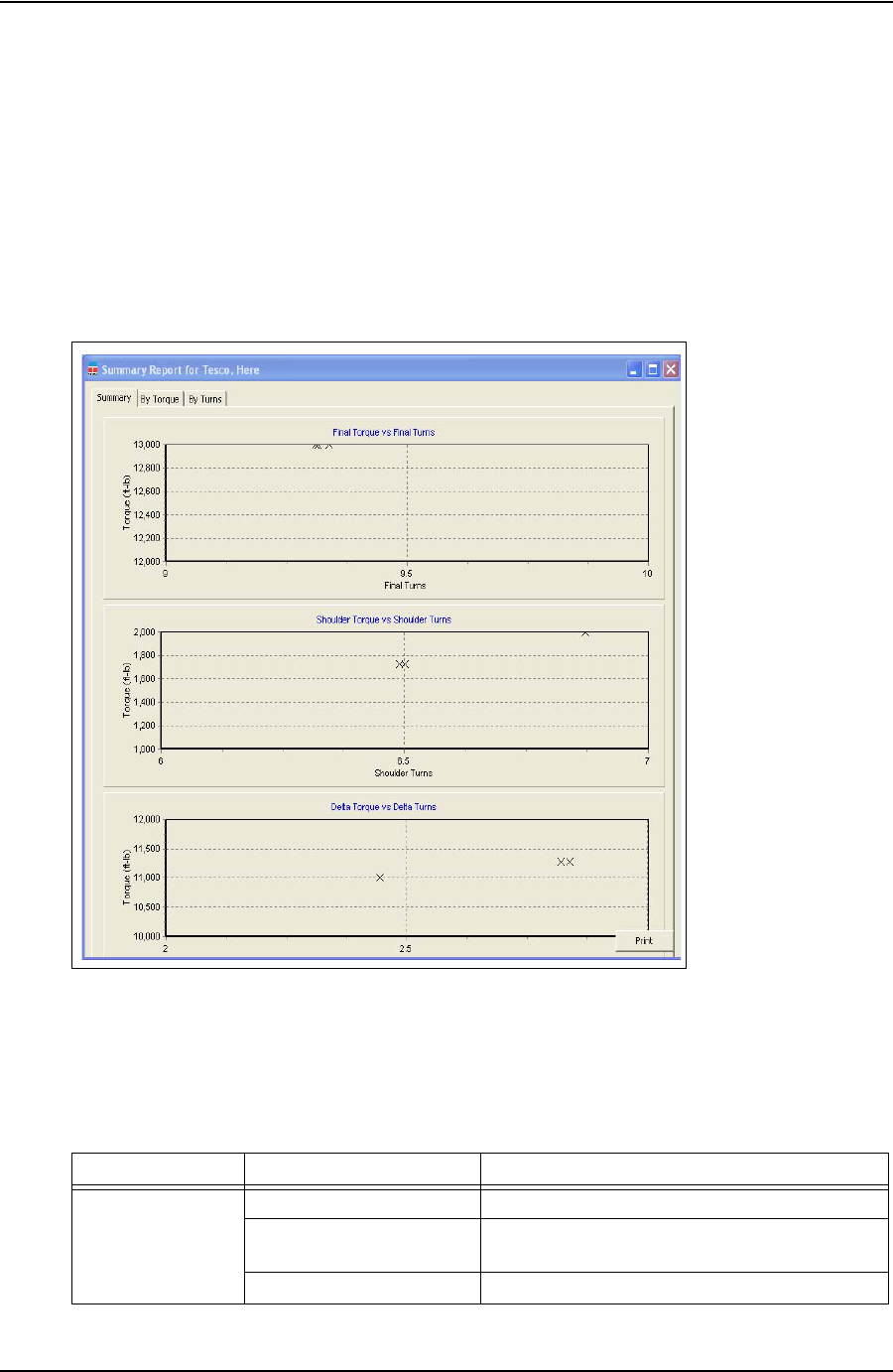
USER GUIDE USING TESTORK MANAGER SOFTWARE
CONTACT: 1-877-TESCO-77 WIRELESS TORQUE TURN SYSTEM WWW.TESCOCORP.COM
INTL: 713-359-7295 51 WWW.TESCOPARTS.COM
G
ENERATING
R
EPORTS
*This section requires more information adding and the procedures to generate reports
documenting.
The section explains how to use TesTORK Manager software to generate reports that provide
information on connections attempts made during the current job.
Figure 4-12: Summary Report Window
Table 4-1: Summary Report Window Dialog
Group Field/Element Name Data/Notes
Charts Final Torque vs Final Turns
Shoulder Torque vs Shoulder
Turns
Delta Torque vs Delta Turns
DRAFT VERSION - INTERNAL USE ONLY
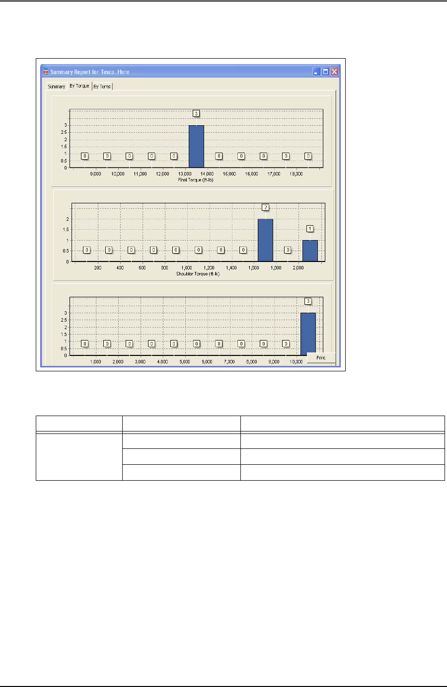
USING TESTORK MANAGER SOFTWARE USER GUIDE
CONTACT: 1-877-TESCO-77 WIRELESS TORQUE TURN SYSTEM WWW.TESCOCORP.COM
INTL: 713-359-7295 52 WWW.TESCOPARTS.COM
Figure 4-13: Summary Report By Torque Window
Table 4-2: Summary Report By Torque Window Dialog
Group Field/Element Name Data/Notes
Charts Final Torque (ft-lb)
Shoulder Torque (ft-lb)
Delta Torque (ft-lb)
DRAFT VERSION - INTERNAL USE ONLY
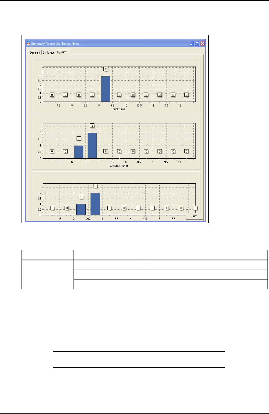
USER GUIDE USING TESTORK MANAGER SOFTWARE
CONTACT: 1-877-TESCO-77 WIRELESS TORQUE TURN SYSTEM WWW.TESCOCORP.COM
INTL: 713-359-7295 53 WWW.TESCOPARTS.COM
The TTS provides view and print report data.
Note: For screen shots and dialog box elements, see
“Reports Side
Panel” on page 22.
Figure 4-14: Summary Report By Turns Window
Table 4-3: Summary Window By Turns Dialog
Group Field/Element Name Data/Notes
Charts Final Turns
Shoulder Turns
Delta Turns
DRAFT VERSION - INTERNAL USE ONLY

USING TESTORK MANAGER SOFTWARE USER GUIDE
CONTACT: 1-877-TESCO-77 WIRELESS TORQUE TURN SYSTEM WWW.TESCOCORP.COM
INTL: 713-359-7295 54 WWW.TESCOPARTS.COM
DRAFT VERSION - INTERNAL USE ONLY

USER GUIDE
CONTACT: 1-877-TESCO-77 WIRELESS TORQUE TURN SYSTEM WWW.TESCOCORP.COM
INTL: 713-359-7295 55 WWW.TESCOPARTS.COM
C
HAPTER
5: S
YSTEM
S
ETTINGS
A
ND
A
DMINIS
-
TRATION
This chapter provides information on configuring TesTORK system settings. All changes to
TesTORK system settings are made in the TesTORK System Settings dialog box. An adminis-
trator passed word is required to access this dialog box.
This chapter also provides information on installing and running TesTORK Manager software.
Note: *Note required confirming how TesTORK Manager software is
normally supplied, i.e. installed and fully configured on the host
computer.
This chapter assumes that the installation, configuration, and calibration procedures for the
TesTORK Wireless Torque / Turn Monitoring System have been completed.
T
ES
TORK S
YSTEM
S
ETTINGS
D
IALOG
B
OX
Caution: The TesTORK Wireless Torque / Turn Monitoring System is
supplied by TESCO with all system settings fully configured. Lim-
ited changes to these settings with be required during normal oper-
ation.
Changes to TesTORK system settings must only be made by suit-
able qualified personal.
*Statement requires verifying and amending as required
The TesTORK System Settings dialog box features the following tabs enabling access to the
various TesTORK system settings.
Table 5-1: TesTORK System Settings dialog box features
Tab
Description of settings
Communications Two tabs are available that feature
TesTORK communication settings and Tes-
TORK base radio communication settings. A Data logging configuration option is
also available.
Calibration
*Please supply description
Graph Settings Enables configuration of graph display settings including; graph axis settings, auto-
shoulder parameters, rpm averaging and connection filtering options.
!
DRAFT VERSION - INTERNAL USE ONLY
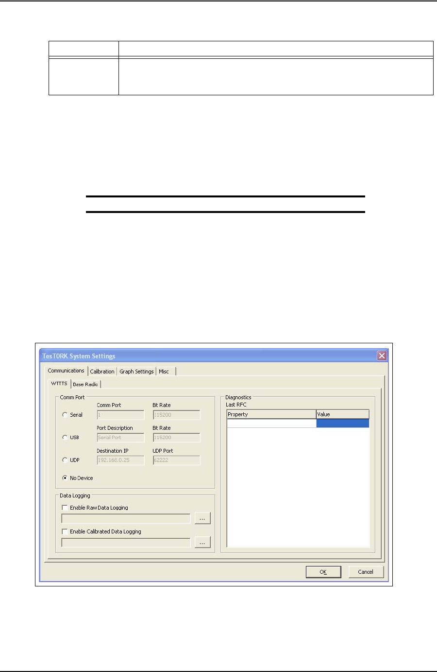
SYSTEM SETTINGS AND ADMINISTRATION USER GUIDE
CONTACT: 1-877-TESCO-77 WIRELESS TORQUE TURN SYSTEM WWW.TESCOCORP.COM
INTL: 713-359-7295 56 WWW.TESCOPARTS.COM
Accessing the System Settings Dialog Box
Use the following procedure to access the TesTORK System Settings dialog box.
1. Click the Hardware button located at the top left of the screen.
The hardware information side panel appears.
Note: For more information, see “Hardware Side Panel” on page 23.
2. Click Configuration.
The Administrator Password Required dialog box appears
3. Type the administrator password in the password text box, and then click Enter.
The TesTORK System Settings tabbed dialog box appears.
Misc Enables configuration of were
TesTORK Manager software saves job data. Also
enables setting of the administrator password, the units of measure and closing a
job file.
Figure 5-1: TesTORK System Settings tabbed dialog box
Table 5-1: TesTORK System Settings dialog box features
Tab
Description of settings
DRAFT VERSION - INTERNAL USE ONLY

USER GUIDE SYSTEM SETTINGS AND ADMINISTRATION
CONTACT: 1-877-TESCO-77 WIRELESS TORQUE TURN SYSTEM WWW.TESCOCORP.COM
INTL: 713-359-7295 57 WWW.TESCOPARTS.COM
Communications settings
Caution: The TesTORK Wireless Torque / Turn Monitoring
System is supplied with all communication settings fully
configured. Only limited changes to these settings may be
required during normal operation.
Changes to TesTORK Communications settings must only be made
by suitable qualified personal.
*Statement requires verifying and amending as required
The Communications settings tabbed dialog box features the following two tabs:
•WTTS
• Base Radio
Note: For a screen shot of the Communications settings tab, see
“TesTORK System Settings dialog box features” on page 55.
WTTS tab
The following system settings are available from the WTTS tab:
Table 5-2: WTTS tab settings
Group Field/Element Name Data/Notes
Comm Port Serial (Radio Button) Comm Port
USB (Radio Button) Port Description
UDP (Radio Button) Destination IP
No Device (Radio Button) There is no TesTORK Device
Data Logging Enable Raw Data Logging
(Check box) If the Enable Raw Data Logging box is checked the
user can select where to save the log file by clicking
on the “
...
” button.
Enable Calibrated Data
Logging
(Check box)
If the Enable Calibrated Data Logging is checked the
user can select where to save the log file by clicking
on the “
...
” button.
!
DRAFT VERSION - INTERNAL USE ONLY

SYSTEM SETTINGS AND ADMINISTRATION USER GUIDE
CONTACT: 1-877-TESCO-77 WIRELESS TORQUE TURN SYSTEM WWW.TESCOCORP.COM
INTL: 713-359-7295 58 WWW.TESCOPARTS.COM
Base Radio tab
**The following are advanced IT settings - Statement required to that effect
The following system settings are available from the Base Radio tab:
Diagnostics (Last
RFC) Link State
Last RFC
Temperature
Battery Life
Battery Type
Pressure
RPM
Last Reset
RF Channel
Current Mode
RFC Rate
RFC Timeout
Stream Rate
Stream Timeout
Pairing Timeout
Table 5-3: Base Radio tab settings
Group Field/Element Name Data/Notes
Comm Port Serial (Radio Button) Comm Port
USB (Radio Button) Port Description
UDP (Radio Button) Destination IP
No Device (Radio Button) There is no TesTORK Device
Commands WTTS Chan
*Please provide explanation
Table 5-2: WTTS tab settings
Group Field/Element Name Data/Notes
DRAFT VERSION - INTERNAL USE ONLY

USER GUIDE SYSTEM SETTINGS AND ADMINISTRATION
CONTACT: 1-877-TESCO-77 WIRELESS TORQUE TURN SYSTEM WWW.TESCOCORP.COM
INTL: 713-359-7295 59 WWW.TESCOPARTS.COM
Diagnostics (Last
Status) Link State
*Please provide explanation to cover all the
following parameters:
Last RFC
Temperature
Battery Life
Battery Type
Pressure
RPM
Last Reset
RF Channel
Current Mode
RFC Rate
RFC Timeout
Stream Rate
Stream Timeout
Pairing Timeout
Table 5-3: Base Radio tab settings
Group Field/Element Name Data/Notes
DRAFT VERSION - INTERNAL USE ONLY
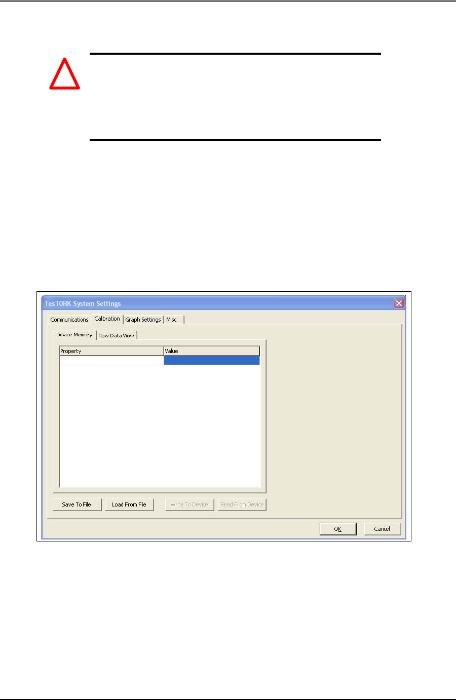
SYSTEM SETTINGS AND ADMINISTRATION USER GUIDE
CONTACT: 1-877-TESCO-77 WIRELESS TORQUE TURN SYSTEM WWW.TESCOCORP.COM
INTL: 713-359-7295 60 WWW.TESCOPARTS.COM
Calibration settings
Caution: The TesTORK Wireless Torque / Turn Monitoring
System is supplied with all calibration settings fully config-
ured. Only limited changes to these settings may be required
during normal operation.
Changes to TesTORK Communications settings must only be made
by suitable qualified personal. .
**The following features are not yet implemented
The Calibration settings tabbed dialog box features the following two tabs:
• Device Memory
•Raw Data View
Figure 5-2: Calibration settings tabbed dialog box
!
DRAFT VERSION - INTERNAL USE ONLY

USER GUIDE SYSTEM SETTINGS AND ADMINISTRATION
CONTACT: 1-877-TESCO-77 WIRELESS TORQUE TURN SYSTEM WWW.TESCOCORP.COM
INTL: 713-359-7295 61 WWW.TESCOPARTS.COM
Device Memory tab
The following system settings are available from the Device Memory tab:
Table 5-4: Device Memory tab settings
Group Field/Element Name Data/Notes
Device Memory Cal Version
*Please provide explanation to cover all the
following parameters:
Cal Revision
Serial Number
Manufacturer Info
Manufacturer Date
Torque 000 Offset
Torque 000 Span
Torque 180 Offset
Torque 180 Span
Tension 000 Offset
Tension 000 Span
Tension 090 Offset
Tension 090 Span
Tension 180 Offset
Tension 180 Span
Tension 270 Offset
Tension 270 Span
Gyro Offset
Gyro Span
Pressure Offset
Pressure Span
Buttons Save To File Save Calibration Data to User-Specified File
Location
Load From File Load Calibration Data from a User-Specified
Location.
Write To Device
Read From Device
DRAFT VERSION - INTERNAL USE ONLY

SYSTEM SETTINGS AND ADMINISTRATION USER GUIDE
CONTACT: 1-877-TESCO-77 WIRELESS TORQUE TURN SYSTEM WWW.TESCOCORP.COM
INTL: 713-359-7295 62 WWW.TESCOPARTS.COM
Raw Data View tab
The following system settings are available from the Raw Data View tab:
Table 5-5: Raw Data View tab settings
Group Field/Element Name Data/Notes
Device Memory Cal Version
*Please provide explanation to cover all the
following parameters:
Cal Revision
Serial Number
Manufacturer Info
Manufacturer Date
Torque 000 Offset
Torque 000 Span
Torque 180 Offset
Torque 180 Span
Tension 000 Offset
Tension 000 Span
Tension 090 Offset
Tension 090 Span
Tension 180 Offset
Tension 180 Span
Tension 270 Offset
Tension 270 Span
Gyro Offset
Gyro Span
Pressure Offset
Pressure Span
Buttons Save To File Save Calibration Data to User-Specified File
Location
Load From File Load Calibration Data from a User-Specified
Location.
Write To Device
Read From Device
DRAFT VERSION - INTERNAL USE ONLY
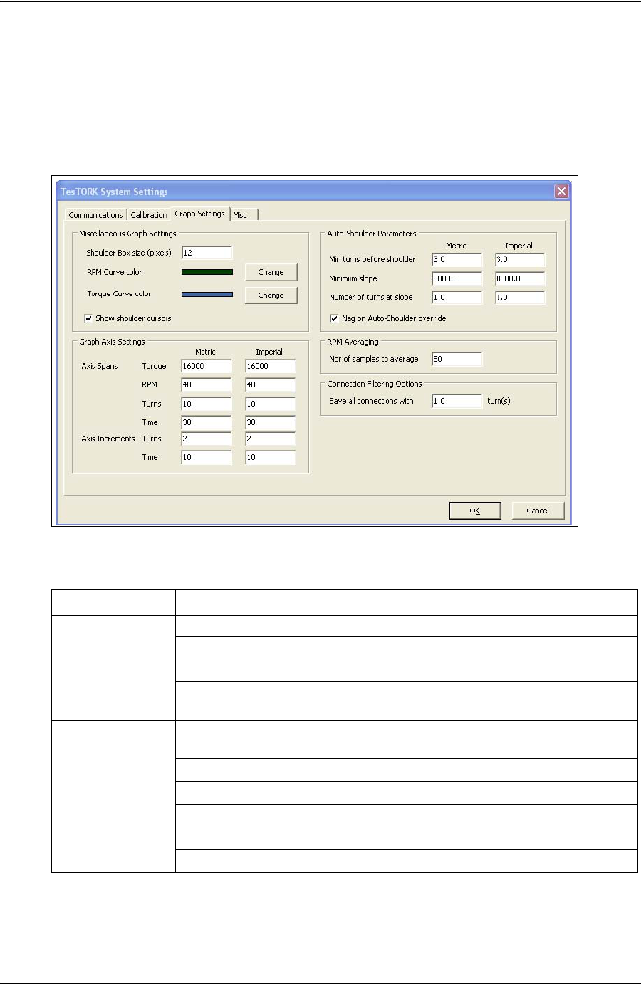
USER GUIDE SYSTEM SETTINGS AND ADMINISTRATION
CONTACT: 1-877-TESCO-77 WIRELESS TORQUE TURN SYSTEM WWW.TESCOCORP.COM
INTL: 713-359-7295 63 WWW.TESCOPARTS.COM
Graph settings
The Graph Settings tab enables configuration of how connection data is displayed during a
connection attempt. *Requires further explanation/notes adding
Figure 5-3: Calibration settings dialog box
Table 5-6: Graph settings
Group Field/Element Name Data/Notes
Miscellaneous Graph
Settings Shoulder Box size (pixels)
RPM Curve Color Specify the Color of the RPM Curve Graph
Torque Curve Color Specify the Color of the Torque Curve Graph
Show shoulder cursors
(Checkbox) If checked, shoulder cursors are displayed in the
graph
Graph Axis Settings
(Axis Spans) Torque
*Please supply an explanation of the following
descriptions:
RPM
Turns
Time
Graph Axis Settings
(Axis Increments) Turns
Time
DRAFT VERSION - INTERNAL USE ONLY
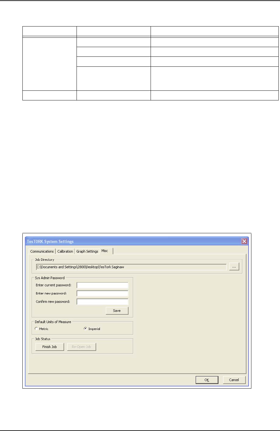
SYSTEM SETTINGS AND ADMINISTRATION USER GUIDE
CONTACT: 1-877-TESCO-77 WIRELESS TORQUE TURN SYSTEM WWW.TESCOCORP.COM
INTL: 713-359-7295 64 WWW.TESCOPARTS.COM
Misc settings
The Misc tab enables configuration of the following features:
• Change the location of the job directory where TesTORK Manager software saves all
configuration data
• Configure the system administrator password
• Define the unit of measure used to display connection data
• Close a job
*Requires further explanation/notes adding
Auto-Shoulder
Parameters Min turns before shoulder
Minimum slope
Number of turns at slope
Nag on Auto-Shoulder
override
(Checkbox)
RPM Averaging Nbr of samples to average
Figure 5-4: System Settings -> Misc Window
Table 5-6: Graph settings
Group Field/Element Name Data/Notes
DRAFT VERSION - INTERNAL USE ONLY

USER GUIDE SYSTEM SETTINGS AND ADMINISTRATION
CONTACT: 1-877-TESCO-77 WIRELESS TORQUE TURN SYSTEM WWW.TESCOCORP.COM
INTL: 713-359-7295 65 WWW.TESCOPARTS.COM
Table 5-7: System Settings -> Misc Dialog
Group Field/Element Name Data/Notes
Job Directory Location of Job Directory The user can navigate to the desired job directory by
clicking the “
...
” button.
Sys Admin Password Enter current password Enter the Current Password into the Text field
Enter new password Enter the New Password into the Text Field
Confirm new password Confirm the New Password by Entering it in the Text
Field
Save (Button) Save the New Password
Default Units of
Measure Metric/Imperial
(Radio Buttons) Select with Which Units of Measurement the WTTTS
will Display
Job Status Finish Job
(Button)
Re-Open Job
(Button)
DRAFT VERSION - INTERNAL USE ONLY

SYSTEM SETTINGS AND ADMINISTRATION USER GUIDE
CONTACT: 1-877-TESCO-77 WIRELESS TORQUE TURN SYSTEM WWW.TESCOCORP.COM
INTL: 713-359-7295 66 WWW.TESCOPARTS.COM
I
NSTALLING
AND
C
ONFIGURING
T
ES
TORK M
ANAGER
S
OFT
-
WARE
*The following contents of this chapter are dependent on how TesTORK Manager soft-
ware will be made available to the customer. Confirmation is required on whether the
software will be supplied installed and configured on a computer, or supplied on a DVD.
Computer Requirements
The following computer requirements are the minimum hardware and software requirements
for the computer hosting WTTS software.
Minimum Hardware
• Dedicated hardware platform
•2 GB of RAM
Supported Operating System
Windows® 7 or Windows 8 operating system
Running WTTS Software
WTTS software is designed to be a portable program. The following options for running the
software are provided.
• The operator can run WTTS software directly from a USB flash drive.
• The operator can run TesTORK Manager software directly from the host computer’s
desktop.
• TesTORK Manager software can be configured to start automatically when the computer
hosting the software starts.
To run TesTORK Manager software from a USB flash drive
Use the following procedure to run TesTORK Manager software directly from a USB flash
drive:
1. Insert the USB flash drive into an available USB port on the computer hosting
TesTORK Manager software.
Note: If the contents of the AutoPlay dialog box doesn’t appear,
navigate to the USB flash drive folder containing the TesTORK
Manager software executable file.
2. Double click the WTTS software executable file.
The Select Job dialog box appears.
DRAFT VERSION - INTERNAL USE ONLY

USER GUIDE SYSTEM SETTINGS AND ADMINISTRATION
CONTACT: 1-877-TESCO-77 WIRELESS TORQUE TURN SYSTEM WWW.TESCOCORP.COM
INTL: 713-359-7295 67 WWW.TESCOPARTS.COM
To run TesTORK Manager software from the host computer desktop
Use the following procedure to run TesTORK Manager software directly from the host com-
puter’s desktop:
1. 1. Insert the USB flash drive.
Note: If the contents of the AutoPlay dialog box doesn’t appear,
navigate to the containing the TesTORK Manager software exe-
cutable file.
2. Browse to and right-click the WTTS software executable file, and then click
Copy.
3. Browse to the host computer’s desktop.
4. Right-click, and then click Paste.
The TesTORK Manager software executable file is pasted on the host computer’s
desktop.
To start TesTORK Manager software automatically when the host computer starts
Use the following procedure to configure TesTORK Manager software to start automatically
when the computer hosting the software starts:
1. Insert the USB flash drive. If the contents of the AutoPlay dialog box doesn’t
appear, navigate to the folder containing the TesTORK Manager software execut-
able file.
2. Browse to and right-click the TesTORK Manager software executable file, and
then click Copy.
3. Select Start > All Programs > Startup
4. Right click on the Startup folder, and then click Open.
The Startup folder opens in Windows Explorer.
5. Right click the Startup folder, and then click Paste.
6. TesTORK Manager software will now start automatically when the computer
hosting the software starts.
Note: To stop TesTORK Manager software from starting automat-
ically, repeat steps 3-4. Then delete the WTTS software shortcut
icon from the startup folder.
DRAFT VERSION - INTERNAL USE ONLY

SYSTEM SETTINGS AND ADMINISTRATION USER GUIDE
CONTACT: 1-877-TESCO-77 WIRELESS TORQUE TURN SYSTEM WWW.TESCOCORP.COM
INTL: 713-359-7295 68 WWW.TESCOPARTS.COM
S
YSTEM
S
TART
U
P
TesTORK software is a portable application that runs on a compatible computer without being
installed in a way that modifies the computer’s configuration information.
Note: For information the computer requirements required to run
TesTORK software, see “TesTORK System Settings Dialog Box”
on page 55.
The TesTORK software executable file can be stored and started from a host computer’s desk-
top. TesTORK software can also be stored and started from portable storage device such as a
USB drive.
A single folder is created when the TesTORK software is started for the first time. The folder
provides a location for all configuration data and data logs for each job. This enables operators
to start TesTORK software and resume work on an existing job without reentering any config-
uration data. New configuration data is entered each time a new job is started.
Use the following procedures to start TesTORK software for the first time on a host computer
To start TesTORK software for the first time on a host computer
1. Ensure the Torque Turn System TesTORK computer is powered up and the
desktop is displayed on the screen.
2. Double-click the TestTORKManager program icon located on the Desktop.
A dialog box appears confirming that a job data directory must be set before
starting the software.
3. Click OK.
The Browse For Folder dialog box appears.
Note: TesTORK software uses the selected folder to store log
files containing configuration and connection data from each job
started in the software.
4. Browse to and select (or create) a suitable folder, and then click OK.
The Select Job dialog box appears.
DRAFT VERSION - INTERNAL USE ONLY

USER GUIDE SYSTEM SETTINGS AND ADMINISTRATION
CONTACT: 1-877-TESCO-77 WIRELESS TORQUE TURN SYSTEM WWW.TESCOCORP.COM
INTL: 713-359-7295 69 WWW.TESCOPARTS.COM
5. Select one of the following options:
If you want to: Complete these steps:
Start an existing job
a. Ensure the Existing Jobs tab is selected.
b. Select a job, and then click OK.
Use the Display Filter buttons to display the most recent jobs or all
jobs.
The TesTORK main screen appears.
Create a new job
a. Click the New Jobs tab.
The New Jobs dialog box appears.
b. Type a client name in the Client box.
c. Type a location in the Location box.
d. Select a unit of measure using the Units of Measure radio buttons.
e. Type a starting connection number in the Starting Connection box.
f. Click OK.
The Create New Job Window appears
g. Type the relevant information or data in the text boxes.
For a description of each text box item, see Figure 2-3 on page 9.
h. Click OK.
The TesTORK Manager software main screen appears.
DRAFT VERSION - INTERNAL USE ONLY

SYSTEM SETTINGS AND ADMINISTRATION USER GUIDE
CONTACT: 1-877-TESCO-77 WIRELESS TORQUE TURN SYSTEM WWW.TESCOCORP.COM
INTL: 713-359-7295 70 WWW.TESCOPARTS.COM
DRAFT VERSION - INTERNAL USE ONLY
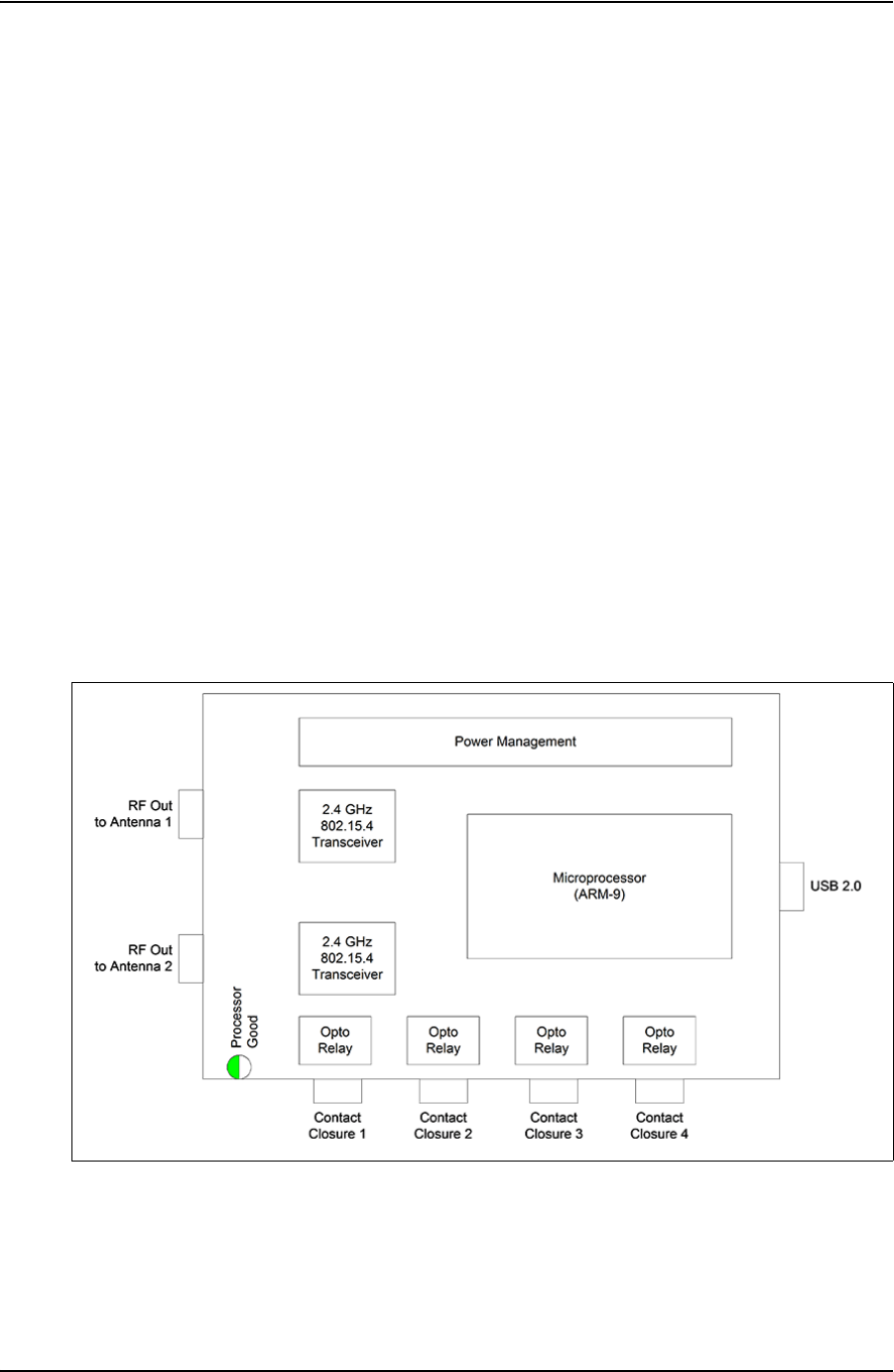
USER GUIDE
CONTACT: 1-877-TESCO-77 WIRELESS TORQUE TURN SYSTEM WWW.TESCOCORP.COM
INTL: 713-359-7295 71 WWW.TESCOPARTS.COM
C
HAPTER
6: TESCO B
ASE
R
ADIO
I
NTRODUCTION
The TESCO Base Radio is a high performance communications system designed to provide
wireless communications with a variety of TESCO products, including:
• TESCO Wireless Torque Turn System (WTTTS)
• TESCO Cement Plug Tracking System (CPTS)
• TESCO Compact Casing Drive System (CCDS)
B
LOCK
D
IAGRAM
Figure 6-1: TESCO Base Radio Block Diagram
DRAFT VERSION - INTERNAL USE ONLY

TESCO BASE RADIO USER GUIDE
CONTACT: 1-877-TESCO-77 WIRELESS TORQUE TURN SYSTEM WWW.TESCOCORP.COM
INTL: 713-359-7295 72 WWW.TESCOPARTS.COM
E
LECTROMAGNETIC
C
OMPATIBILITY
N
OTICE
FCC
This device complies with part 15 of the FCC Rules. Operation is subject to the following two
conditions: (1) This device may not cause harmful interference, and (2) this device must
accept any interference received, including interference that may cause undesired operation.
The grantee is not responsible for any changes or modifications not expressly approved by the
party responsible for compliance. Such modifications could void the user’s authority to oper-
ate this device.
This device has been tested and found to comply with the limits for a Class B digital device,
pursuant to part 15 of the FCC Rules. These limits are designed to provide reasonable protec-
tion against harmful interference in a residential installation. This device generates, uses and
can radiate radio frequency energy and, if not installed and used in accordance with the
instructions, may cause harmful interference to radio communications. However, there is no
guarantee that interference will not occur in a particular installation. If this device does cause
harmful interference to radio or television reception, which can be determined by turning this
device off and on, the user is encouraged to try to correct the interference by one or more of
the following measures:
• Reorient or relocate the receiving antenna.
• Increase the separation between this device and receiver.
• Connect this device into an outlet on a circuit different from that to which the
receiver is connected.
•Consult the dealer or an experienced radio/TV technician for help.
IC RSS 210
This device complies with Industry Canada licence-exempt RSS standard(s). Operation is
subject to the following two conditions: (1) this device may not cause interference, and (2) this
device must accept any interference, including interference that may cause undesired
operation of the device.
Le présent appareil est conforme aux CNR d’Industrie Canada applicables aux appareils radio
exempts de licence. L’exploitation est autorisée aux deux conditions suivantes : (1) l’appareil
ne doit pas produire de brouillage, et (2) l’utilisateur de l’appareil doit accepter tout brouillage
radioélectrique subi, même si le brouillage est susceptible d’en compromettre le
fonctionnement.
DRAFT VERSION - INTERNAL USE ONLY
USER GUIDE TESCO BASE RADIO
CONTACT: 1-877-TESCO-77 WIRELESS TORQUE TURN SYSTEM WWW.TESCOCORP.COM
INTL: 713-359-7295 73 WWW.TESCOPARTS.COM
S
AFETY
The TESCO Base Radio is intended to be used in locations where hazardous gases may
occasionally be present. It meets the requirements of IEC-60079-11 for use in Zone 2 Group
IIB; CSA 22.2 No. 213 and ANSI/ISA 12.12.01-2012 Class 1 Division 2, gas groups C and D.
Note: Only units with either a Special Inspection sticker or
Model Certification label shall be used in locations where
hazardous gases may be present.
4.1.1 CSA 22.2 No. 213
THIS EQUIPMENT IS SUITABLE FOR USE IN CLASS 1, DIVISION 2, GROUPS C AND
D, OR NON-HAZARDOUS LOCATIONS ONLY.
Warning! EXPLOSION HAZARD - SUBSTITUTION OF
COMPONENTS MAY IMPAIR SUITABILITY FOR
CLASS 1, DIVISION 2.
Avertissement! RISQUE D’EXPLOSION - LA SUBSTITUTION
DES COMPOSANTS PEUT RENDRE CE MATERIEL
INACCEPTABLE POUR LES EMPLACEMENTS DE
CLASSE 1, DIVISION 2.
Warning! EXPLOSION HAZARD - DO NOT DISCONNECT
EQUIPMENT UNLESS POWER HAS BEEN
SWITCHED OFF OR THE AREA IS KNOWN TO BE
NON-HAZARDOUS.
Avertissement! RISQUE D’EXPLOSION - AVANT DE
DECONNECTER L’EQUIPEMENT, COUPER LE
COURANT OU S’ASSURER QUE
L’EMPLACEMENT EST DESIGNE NON
DANGEREUX
4.1.2 ANSI/ISA 12.12.01
U
SER
C
ONTROLS
The TESCO Base Radio is designed to be used as part of a TESCO Wireless System. All
control of the Base Radio is through the TESCO Software.
There are no physical user controls on the TESCO Base Radio.
!
!
!
!
DRAFT VERSION - INTERNAL USE ONLY
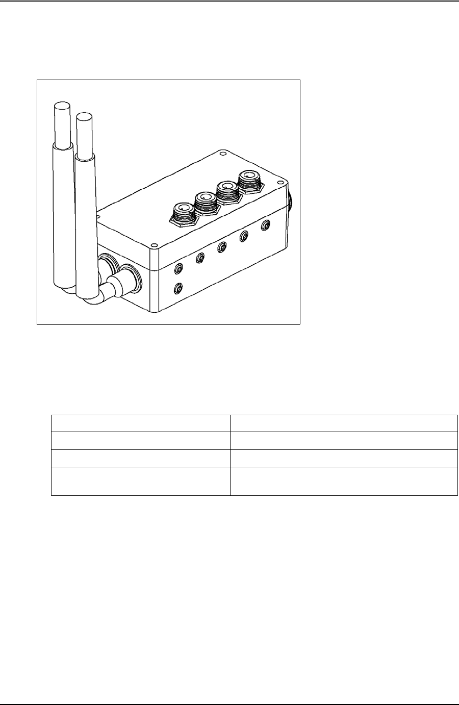
TESCO BASE RADIO USER GUIDE
CONTACT: 1-877-TESCO-77 WIRELESS TORQUE TURN SYSTEM WWW.TESCOCORP.COM
INTL: 713-359-7295 74 WWW.TESCOPARTS.COM
S
PECIFICATIONS
Environmental
The TESCO Base Radio is designed for outdoor use.
Radio
The TESCO Base Radio contains two radio transceivers. This allows the TESCO Base Radio
to receive streaming real time measurement data from the Wireless Torque Turn Tension
System on one channel while at the same time monitor supervisory devices such as the
TESCO Compact Casing Drive System on the other channel.
Both radio channels are under control of the same microprocessor and the software ensures
that the two radio channels operate on different frequency channels and never transmit at the
same time.
Figure 6-2: Base Radio
Table 6-1: TESCO Base Radio Environmental Specifications
Operating Temperature Range
-40 °C to +70 °C.
Storage Temperature
-40 °C to +85 °C.
Operating and Storage Humidity
10% to 95%
Ingress Protection
IP66 (when used with recommended connectors or dust
caps)
DRAFT VERSION - INTERNAL USE ONLY

USER GUIDE TESCO BASE RADIO
CONTACT: 1-877-TESCO-77 WIRELESS TORQUE TURN SYSTEM WWW.TESCOCORP.COM
INTL: 713-359-7295 75 WWW.TESCOPARTS.COM
The following specifications apply to both radio links:
Contact Closures
The TESCO Base Radio provides up to four opto-isolated solid-state contact closures that may
be used for a variety of control alerting purposes. The state of these closures is set through the
main application software.
Power
Power to the TESCO Base Radio is provided by the host computer through the USB
connector.
Table 6-2: Radio Specifications
Parameter
Specification
Protocol
Subset of IEEE 802.15.4
Modulation
GMSK, DSSS at 250 kb/s, 2 Mchip/s
FCC/IC Emission Designator
2M42G7D
Frequency Band
2.405 to 2.480 GHz (channel centers)
Standard Channels
Channel 11 (2.405 GHz center)
Channel 15 (2.425 GHz center)
Channel 20 (2.450 GHz center)
Channel 25 (2.475 GHz center)
Channel Bandwidth
3 MHz max. (TBV)
RF Transmit Power
-5 dBm max.
Connector
WTTTS: N-Type
General Purpose: RP-TNC
Allowable Antenna Gain
+5 dBi max.
Table 6-3: Contact Closure Specifications
Parameter
Specification
Configuration
Form A (Normally Open)
Load Current
100 mA max.
Off-State Voltage
350 V Peak (AC or DC)
On-State Resistance
35 ohms max, (t < 1 s); 50 ohms max, (continuous)
Isolation Voltage
1500 Vrms min.
Turn-On Time
1 ms max.
Turn-Off Time
1 ms max.
Connector
Amphenol USBBF TV 2 1 G 13-13
Table 6-4: Base Radio Power Specifications
Parameter
Specification
Input Voltage Range
4.5 - 5.5 Vdc
DRAFT VERSION - INTERNAL USE ONLY

TESCO BASE RADIO USER GUIDE
CONTACT: 1-877-TESCO-77 WIRELESS TORQUE TURN SYSTEM WWW.TESCOCORP.COM
INTL: 713-359-7295 76 WWW.TESCOPARTS.COM
Digital Interface
The interface to the computer is by means of a single USB connector.
M
OUNTING
The TESCO Base Radio may be mounted to the back of the Labresav computer by means of
the Mounting Adapter, TESCO part number 5036743.
Alternatively, it may be mounted in any convenient location within reach of the computer.
Note: If mounted in a location exposed to weather, ensure
that all unused connectors have dust-caps installed and
properly fitted.
When both radio channels are used, to minimize the risk of generating emissions that could
interfere with other radio systems, ensure the two antennas are spaced at least 8” (20 cm)
apart.
In order to comply with the requirements for exposure to radio frequency energy, all antennas
must be mounted at least 8” (20 cm) from all persons.
O
PERATING
I
NSTRUCTIONS
The TESCO Base Radio is intended to be used only as part of a TESCO Wireless System. To
operate the TESCO Base Radio, connect it by means of a USB cable to a computer running the
TESCO Wireless System software.
M
AINTENANCE
The TESCO Base Radio contains no user serviceable parts.
Current
200 mA max.
Table 6-5: Digital Interface Specifications
Parameter
Specification
Connector Type
USB Type-B
Interface Standard
USB 2.0, Serial Port Protocol
Table 6-4: Base Radio Power Specifications
Parameter
Specification
DRAFT VERSION - INTERNAL USE ONLY
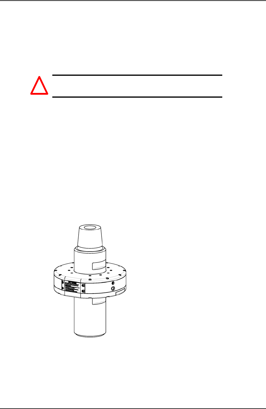
USER GUIDE CHANGING THE BATTERY
CONTACT: 1-877-TESCO-77 WIRELESS TORQUE TURN SYSTEM WWW.TESCOCORP.COM
INTL: 713-359-7295 1 WWW.TESCOPARTS.COM
A
PPENDIX
A: C
HANGING
T
HE
B
ATTERY
C
AUTIONS
AND
W
ARNINGS
Warning! This equipment contains intrinsically safe
circuitry. Substitution of components may
impair intrinsic safety.
To reduce the risk of ignition of a flammable or explosive atmosphere when servicing the
battery be sure the battery seals are seated properly and sealing surfaces are clean.
• The battery is rechargeable
• The battery is Class 1 Div 1 certified
• The battery terminals are the same left to right. The battery can be inserted upside down
provided the terminals are facing inwards.
T
ORQUE
S
UB
B
ATTERY
C
HANGING
1. Turn the sub so the battery compartment is easily accessible.
Figure A-1: Place the TesTORK
!
DRAFT VERSION - INTERNAL USE ONLY
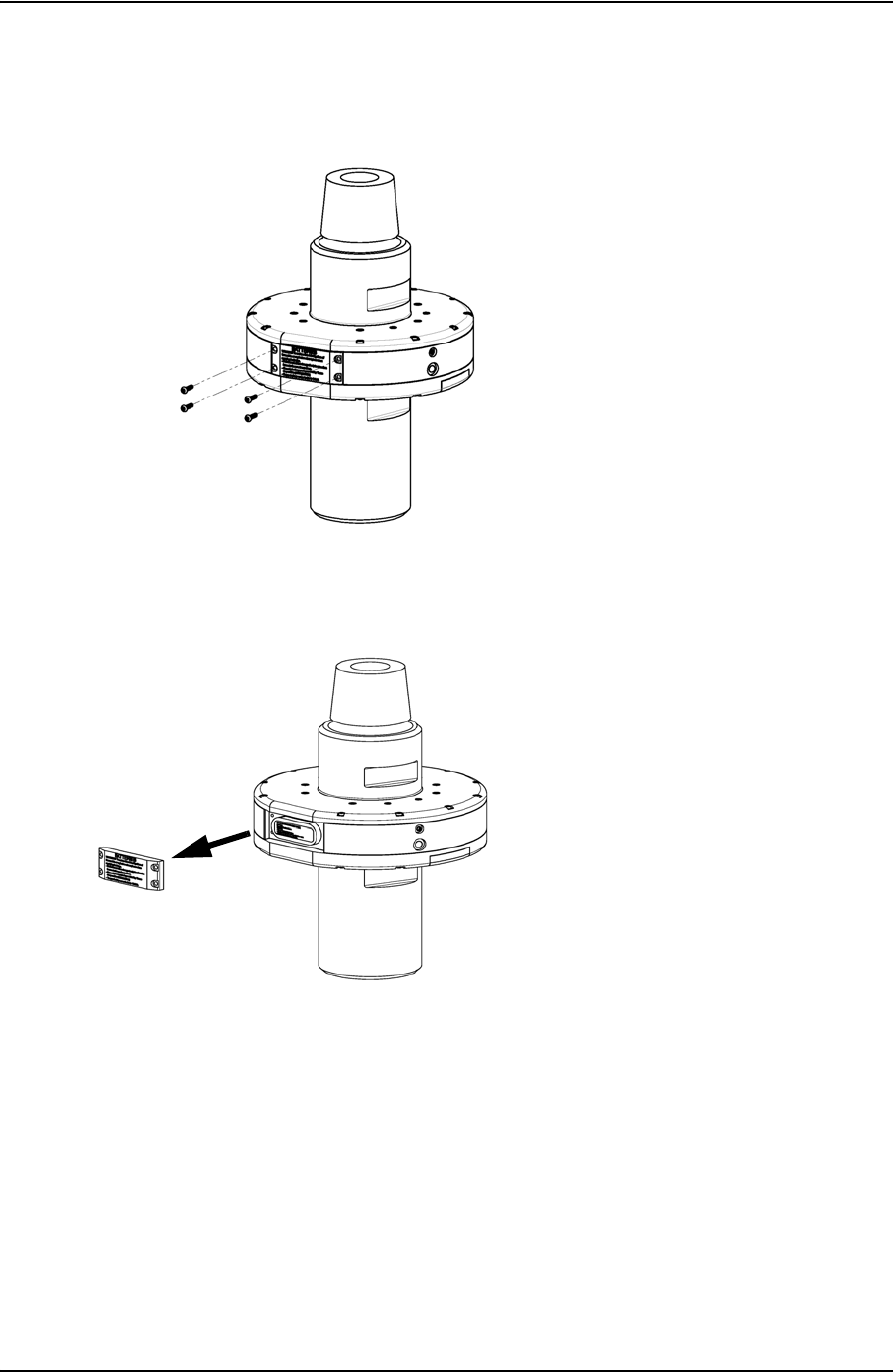
CHANGING THE BATTERY USER GUIDE
CONTACT: 1-877-TESCO-77 WIRELESS TORQUE TURN SYSTEM WWW.TESCOCORP.COM
INTL: 713-359-7295 2 WWW.TESCOPARTS.COM
2. Using a 5/16” hex key, remove the four cap screws securing the battery
compartment cover plate.
3. Remove the battery compartment cover plate.
Figure A-2: Remove cap screws
Figure A-3: Remove battery cover
DRAFT VERSION - INTERNAL USE ONLY
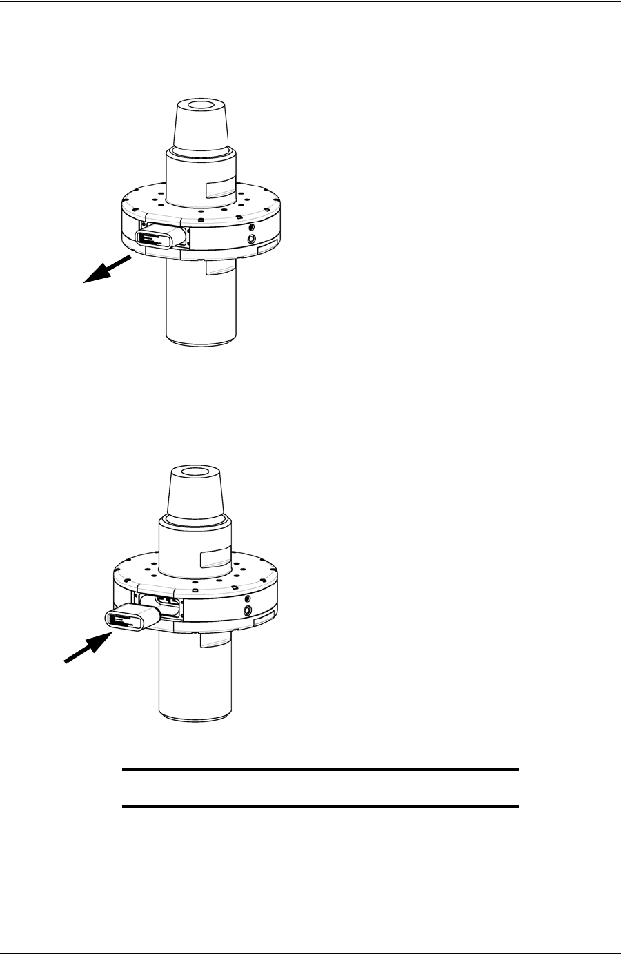
USER GUIDE CHANGING THE BATTERY
CONTACT: 1-877-TESCO-77 WIRELESS TORQUE TURN SYSTEM WWW.TESCOCORP.COM
INTL: 713-359-7295 3 WWW.TESCOPARTS.COM
4. Pull out the existing battery.
5. Push in the new battery.
6. Replace the battery compartment cover plate and secure with the four cap screws.
Note: The TesTORK system will automatically power up when
the battery is fitted in the battery compartment.
Figure A-4: Remove battery cover
Figure A-5: Refit battery
DRAFT VERSION - INTERNAL USE ONLY

CHANGING THE BATTERY USER GUIDE
CONTACT: 1-877-TESCO-77 WIRELESS TORQUE TURN SYSTEM WWW.TESCOCORP.COM
INTL: 713-359-7295 4 WWW.TESCOPARTS.COM
DRAFT VERSION - INTERNAL USE ONLY

USER GUIDE TTS CHECKLISTS AND FORMS
CONTACT: 1-877-TESCO-77 WIRELESS TORQUE TURN SYSTEM WWW.TESCOCORP.COM
INTL: 713-359-7295 1 WWW.TESCOPARTS.COM
A
PPENDIX
B: TTS C
HECKLISTS
AND
F
ORMS
The following forms are available for the Torque Turn System. See the following pages for
examples of each form.
* Some of the following checklist require updating
• Form #881020 - Job Safety Analysis Sheet
• Form #881051 - Wireless Torque Turn System Pre-Job Information Sheet
•Form #881032 - Torque Turn System Required Data Sheet
• Form #881028 - Torque Turn System Tool Kit Inventory List
• Form #2400003 - Wireless Torque Turn System Inventory List
• Form #881042 - Final Checklist
DRAFT VERSION - INTERNAL USE ONLY

TTS CHECKLISTS AND FORMS USER GUIDE
CONTACT: 1-877-TESCO-77 WIRELESS TORQUE TURN SYSTEM WWW.TESCOCORP.COM
INTL: 713-359-7295 2 WWW.TESCOPARTS.COM
J
OB
S
AFETY
A
NALYSIS
W
ORKSHEET
Form Description
The Job Safety Analysis Sheet is an internal document for all TESCO workers including field,
shop, and office employees.
This document is to be filled out by the supervisor at the beginning of each job.
DRAFT VERSION - INTERNAL USE ONLY
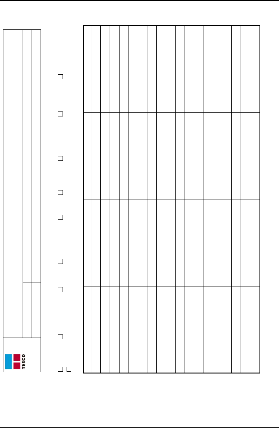
USER GUIDE TTS CHECKLISTS AND FORMS
CONTACT: 1-877-TESCO-77 WIRELESS TORQUE TURN SYSTEM WWW.TESCOCORP.COM
INTL: 713-359-7295 3 WWW.TESCOPARTS.COM
Job Safety Analysis Worksheet
Job #: Job Location: Analysis Made By:
Date: Job Supervisor: Analysis Reviewed With:
Form #881020 Rev A - Job Safety Analysis Worksheet 1 Tesco Corporation 2004: Updated June 3, 05
Personal Protective Equipment Required and/or Recommended
Hard Hat Steel Toe Boots Gloves Safety Glasses Apron Respirator Safety Harness Face Shield Rubber Gloves
Other: _________________ _____________________ ________________________
Sequence of Basic Job Step Potential Accidents or Hazards Recommended Safe Job Procedures Name of Person Performing Review
DRAFT VERSION - INTERNAL USE ONLY

TTS CHECKLISTS AND FORMS USER GUIDE
CONTACT: 1-877-TESCO-77 WIRELESS TORQUE TURN SYSTEM WWW.TESCOCORP.COM
INTL: 713-359-7295 4 WWW.TESCOPARTS.COM
T
ORQUE
T
URN
S
YSTEM
: P
RE
-J
OB
I
NFORMATION
C
HECKLIST
Form Description
The pre-job information checklist is a collection of rig information.
The pre-job information checklist is partially filled out by the TESCO Service Manager then
sent to the field office to collect the remaining information. The information on this checklist
is used by the job supervisor responsible for the torque turn job in the field.
DRAFT VERSION - INTERNAL USE ONLY
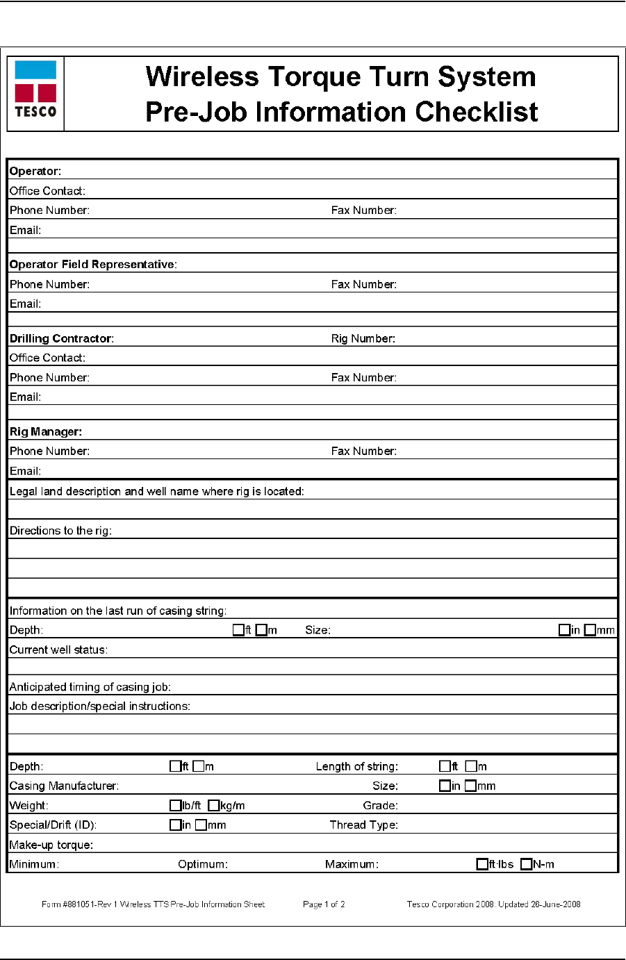
USER GUIDE TTS CHECKLISTS AND FORMS
CONTACT: 1-877-TESCO-77 WIRELESS TORQUE TURN SYSTEM WWW.TESCOCORP.COM
INTL: 713-359-7295 5 WWW.TESCOPARTS.COM
DRAFT VERSION - INTERNAL USE ONLY
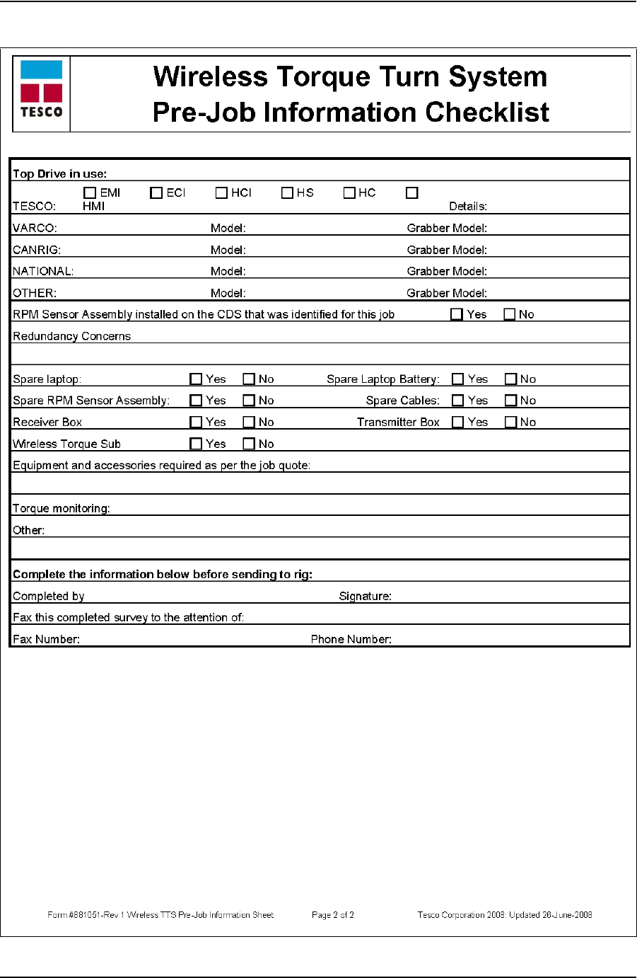
TTS CHECKLISTS AND FORMS USER GUIDE
CONTACT: 1-877-TESCO-77 WIRELESS TORQUE TURN SYSTEM WWW.TESCOCORP.COM
INTL: 713-359-7295 6 WWW.TESCOPARTS.COM
DRAFT VERSION - INTERNAL USE ONLY

USER GUIDE TTS CHECKLISTS AND FORMS
CONTACT: 1-877-TESCO-77 WIRELESS TORQUE TURN SYSTEM WWW.TESCOCORP.COM
INTL: 713-359-7295 7 WWW.TESCOPARTS.COM
T
ORQUE
T
URN
S
YSTEM
: R
EQUIRED
D
ATA
S
HEET
Form Description
The required data sheet is used for information collection and is to be filled out by TESCO
personnel after information has been received from the rig on the Pre-Job Information Check-
list (form # 881031).
If some information is not received from the rig, the TESCO job supervisor will be required to
supply the remaining information while on site. A rig survey is required.
DRAFT VERSION - INTERNAL USE ONLY
TTS CHECKLISTS AND FORMS USER GUIDE
CONTACT: 1-877-TESCO-77 WIRELESS TORQUE TURN SYSTEM WWW.TESCOCORP.COM
INTL: 713-359-7295 8 WWW.TESCOPARTS.COM
Torque Turn System
Required Data Sheet
Form #881032 Rev A TTS Required Data Sheet Page 1 of 1 Tesco Corporation 2005: Updated 3 June 2005
The following casing information is required to set the parameters for the Torque/Turn or Torque/Time monitors. Tesco
will ONLY use operator supplied data. Rig Survey checklist must be completed by a Tesco Representative.
Rig Survey
Required
Oil Company: Well Name:
Drilling Supervisor: L.S.D.:
Drilling Engineer: Contractor:
Wellsite Supervisor: Rig Number:
Wellsite Phone Number:
Top Drive Make:
Top Drive Model:
Projected Casing Depth:
Project Date of Job:
Calibration check interval: Every joints
(Tesco recommends checking a minimum of once at the mid-point.)
Casing Information
Manufacturer:
Connection Name:
Casing Grade:
Casing Weight: lb/ft or kg/m (Check unit of measure)
Torque Target
Minimum Make Up Torque:
lbf-ft or N-m (Check unit of measure)
Optimum Make Up Torque:
lbf-ft or N-m
Maximum Make Up Torque:
lbf-ft or N-m
Maximum Make Up RPM:
Shoulder Target
Turns to Shoulder: Turns +/-:
Post-Shoulder Turns: Turns +/-:
Trigger Torque:
lbf-ft or N-m (Check unit of measure)
Maximum Shoulder RPM:
The above information was supplied and approved by the following:
Name (print):
Position/title of approver:
Date:
Signature:
DRAFT VERSION - INTERNAL USE ONLY

USER GUIDE TTS CHECKLISTS AND FORMS
CONTACT: 1-877-TESCO-77 WIRELESS TORQUE TURN SYSTEM WWW.TESCOCORP.COM
INTL: 713-359-7295 9 WWW.TESCOPARTS.COM
T
ORQUE
T
URN
S
YSTEM
: T
OOL
K
IT
I
NVENTORY
C
HECKLIST
Form Description:
The tool kit inventory checklist provides information for the job supervisor who is responsible
to maintain control of all tools.
DRAFT VERSION - INTERNAL USE ONLY
TTS CHECKLISTS AND FORMS USER GUIDE
CONTACT: 1-877-TESCO-77 WIRELESS TORQUE TURN SYSTEM WWW.TESCOCORP.COM
INTL: 713-359-7295 10 WWW.TESCOPARTS.COM
Torque Turn System
Tool Kit Inventory Checklist
Tesco Form #881028 Updated June 3, 2005 TTS Tool Kit Checklist © Tesco Corporation, 2005
Item Description Part # Qty Origin Item Size Going to Site Leaving Site
1 Battery - for Flashlight 1623 1 USA Spring Top
2 Flashlight 2766 1
3 Bulb - for Flashlight 6054 4 Hong Kong 6 Volt
4 Duct Tape - Roll 1584 2 USA 2"
5 Stainless Steel Wire - Roll 2909 1 CHINA 0.032"
6 Tie Wrap - Plastic 5381 100 USA ¼" x 12"
7 Tie Wrap - Plastic 805 100 USA 5/16" x 30"
8 Tie Wrap - Plastic 806 50 USA 1/8" x 7"
9 Hex Key Set - Short Arm 1289 1 USA 0.028" to 5/8"
10 Hex Key Set - Short Arm - Metric 1286 1 USA 0.7 mm to 10 mm
11 Fluke Meter - Process 787 18012 1 USA
12 Fuse for Fluke Meter 0487 2 USA 11 Amp
13 Fuse for Fluke Meter 0491 2 USA 44/100 Amp
14 Alligator Clip 3794 2 USA Red and Black
15 Solder 60/40 6465 1 CANADA 60/40
16 Solder for Pyropen 7475 1 CANADA 3/32/Silver
17 Butane for Pyropen 1650 1 USA 145 g
18 Pyropen 1524 1 USA cordless
19 Vise Grip 1400 1 USA 10”
20 Side Cutting Pliers 1368 1 TAIWAN 7”
21 Wire Stripper 1526 1 USA
22 Unidriver 1380 1 TAIWAN 13 PC.
23 Utility Knife 1293 1 JAPAN L2hd
24 Small Torque Wrench 5814 1 USA
25 Terminating Screw Driver 4277 1 USA 1/8”x6”
26
27
The Above information was collected by?
Going to site Name (print): Signature:
Leaving site Name (print): Signature:
*This checklist requires updating
DRAFT VERSION - INTERNAL USE ONLY

USER GUIDE TTS CHECKLISTS AND FORMS
CONTACT: 1-877-TESCO-77 WIRELESS TORQUE TURN SYSTEM WWW.TESCOCORP.COM
INTL: 713-359-7295 11 WWW.TESCOPARTS.COM
T
ORQUE
T
URN
S
YSTEM
: I
NVENTORY
C
HECKLIST
Form Description
The inventory list is to be filled out by the job supervisor prior to arriving and leaving the job
site.
The purpose of this list is to keep track of all equipment and to assist with information needed
to prepare exportation papers for the equipment.
*This checklist requires updating
DRAFT VERSION - INTERNAL USE ONLY
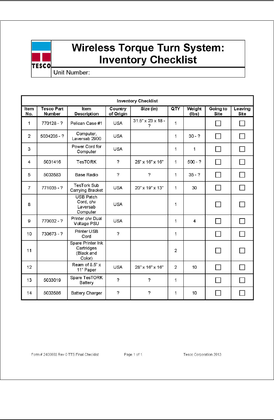
TTS CHECKLISTS AND FORMS USER GUIDE
CONTACT: 1-877-TESCO-77 WIRELESS TORQUE TURN SYSTEM WWW.TESCOCORP.COM
INTL: 713-359-7295 12 WWW.TESCOPARTS.COM
DRAFT VERSION - INTERNAL USE ONLY

USER GUIDE TTS CHECKLISTS AND FORMS
CONTACT: 1-877-TESCO-77 WIRELESS TORQUE TURN SYSTEM WWW.TESCOCORP.COM
INTL: 713-359-7295 13 WWW.TESCOPARTS.COM
T
ORQUE
T
URN
S
YSTEM
: F
INAL
C
HECKLIST
Form Description
The final checklist is to be completed by the job supervisor before leaving the job site.
The purpose of this checklist is to ensure that the crew is equipped with all the tools needed to
complete the job.
DRAFT VERSION - INTERNAL USE ONLY
TTS CHECKLISTS AND FORMS USER GUIDE
CONTACT: 1-877-TESCO-77 WIRELESS TORQUE TURN SYSTEM WWW.TESCOCORP.COM
INTL: 713-359-7295 14 WWW.TESCOPARTS.COM
Torque Turn System: Final Checklist
Form # 881042 Rev A TTS Final Checklist Page 1 of 1 Tesco Corporation 2005: Updated June 3, 2005
Final Check List Item Complete Comments
Box 1 on Truck
Box 2 on Truck
Casing Tool on Truck
Tool Box on Truck
Pre-Job Forms Completed
Directions To The Rig
Communications Devices
Personal Computer
Fuel For The Vehicle
Additional Items
The above check was performed by:
Name (print): Signature:
DRAFT VERSION - INTERNAL USE ONLY
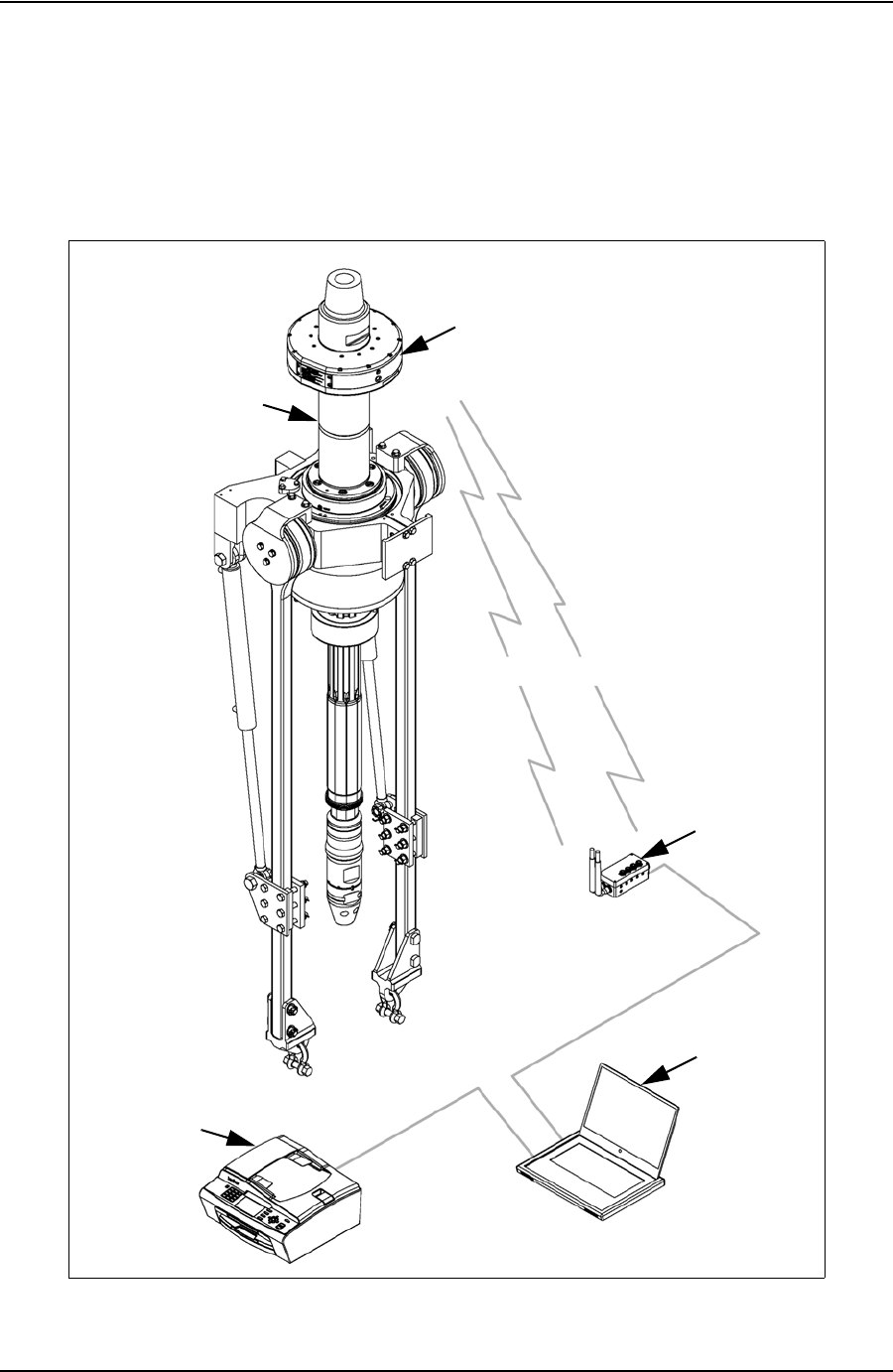
USER GUIDE DEVICE SPECIFICATIONS
CONTACT: 1-877-TESCO-77 WIRELESS TORQUE TURN SYSTEM WWW.TESCOCORP.COM
INTL: 713-359-7295 1 WWW.TESCOPARTS.COM
A
PPENDIX
C: D
EVICE
S
PECIFICATIONS
T
ES
TORK D
EVICE
N
ETWORK
T
ES
TORK
T
ES
TORK S
UB
W
IRELESS
W
IRELESS
B
ASE
R
ADIO
C
OMPUTER
P
RINTER
DRAFT VERSION - INTERNAL USE ONLY
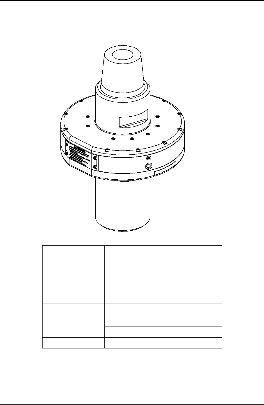
DEVICE SPECIFICATIONS USER GUIDE
CONTACT: 1-877-TESCO-77 WIRELESS TORQUE TURN SYSTEM WWW.TESCOCORP.COM
INTL: 713-359-7295 2 WWW.TESCOPARTS.COM
W
IRELESS
T
ORQUE
AND
T
ENSION
S
UB
Description Details
Function Measure and transmit torque and tension
values at a rate of 100 Hz
Location Between top drive and CDS tool
Designed for UL & CSA Class 1, Div. 1
Hazard Location (pending certification)
Connection API 6-5/8” Regular Thread Pin Up
API 6-5/8” Regular Thread Box Down
Battery Powered, No electrical connections
Primary Load Rating 500 ton - API 8C
DRAFT VERSION - INTERNAL USE ONLY

USER GUIDE DEVICE HAZARDOUS LOCATION RATINGS
CONTACT: 1-877-TESCO-77 WIRELESS TORQUE TURN SYSTEM WWW.TESCOCORP.COM
INTL: 713-359-7295 1 WWW.TESCOPARTS.COM
A
PPENDIX
D: D
EVICE
H
AZARDOUS
L
OCATION
R
ATINGS
The following table provides information on the hazardous location rating for each TesTORK
system device. *Please check the following information for accuracy
Table D-1: Device hazardous location ratings
Device TESCO
Part
number
International Electrical
Commission (IEC) Canadian Standards Association
(CSA) / Underwriters
Laboratories (UL)
TesTORK housing
(including TesTORK
sub)
5031416 Zone 1
Base radio 5033583 Class 1 Div 2
TESCO supplied
computers:
• Industrial touch-
screen PC
• Laptop
5034206
5034206
Class 1 Div 2
Class 1 Div 2
Battery pack -
rechargeable
Battery pack - non
rechargeable
Zone 1 (when fitted in
TesTORK housing)
Zone 1 (when fitted in
TesTORK housing)
Battery charger 5033586 Not yet rated Not yet rated
DRAFT VERSION - INTERNAL USE ONLY

DEVICE HAZARDOUS LOCATION RATINGS USER GUIDE
CONTACT: 1-877-TESCO-77 WIRELESS TORQUE TURN SYSTEM WWW.TESCOCORP.COM
INTL: 713-359-7295 2 WWW.TESCOPARTS.COM
DRAFT VERSION - INTERNAL USE ONLY