Micron Electronics 0508201300001 3G GPS tracker User Manual VL3000 Manager Tool User Guide Ver1
Micron Electronics LLC. 3G GPS tracker VL3000 Manager Tool User Guide Ver1
UserManual.wiki
>
Micron Electronics
>
0508201300001 User Manual
VL3000 Manager Tool User Guide Ver1
Navigation menu
Upload a User Manual
Namespaces
Wiki Guide
HTML
PDF
Info
Views
User Manual
Discussion / Help
Navigation
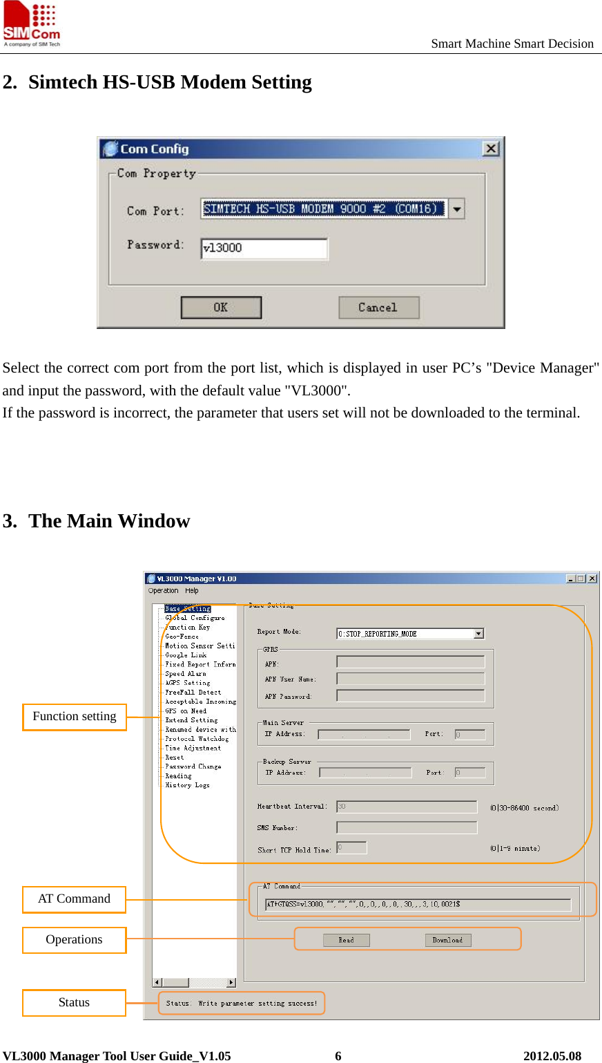
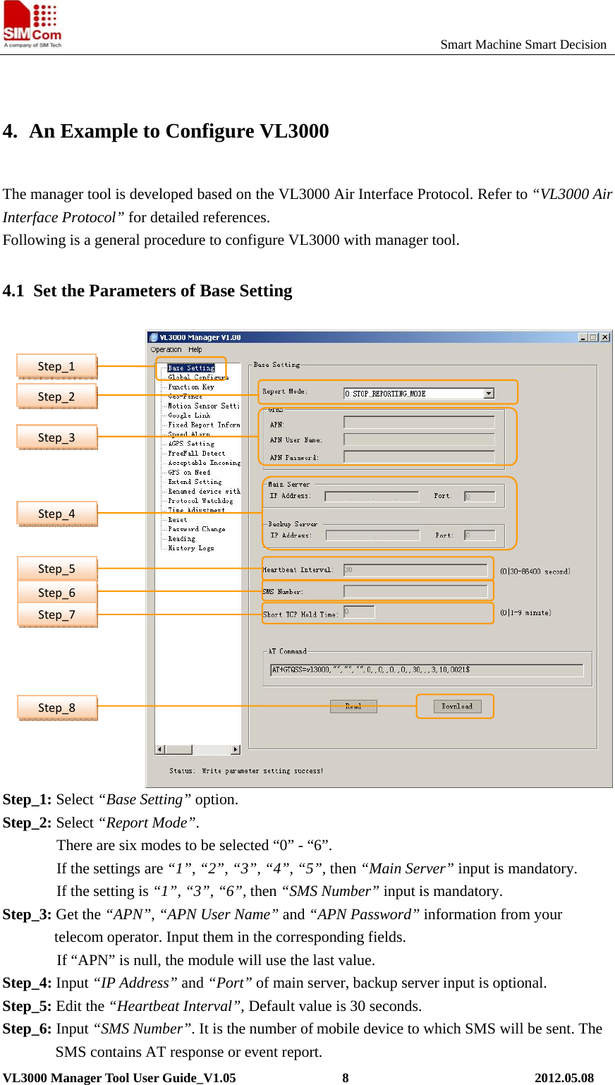
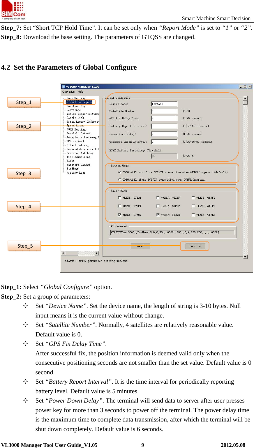
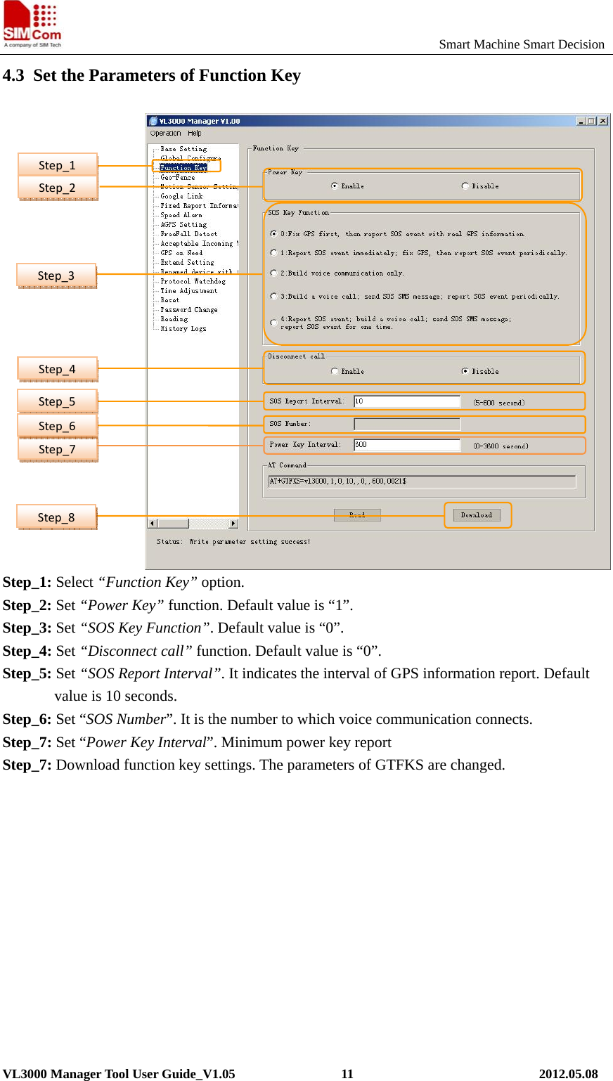
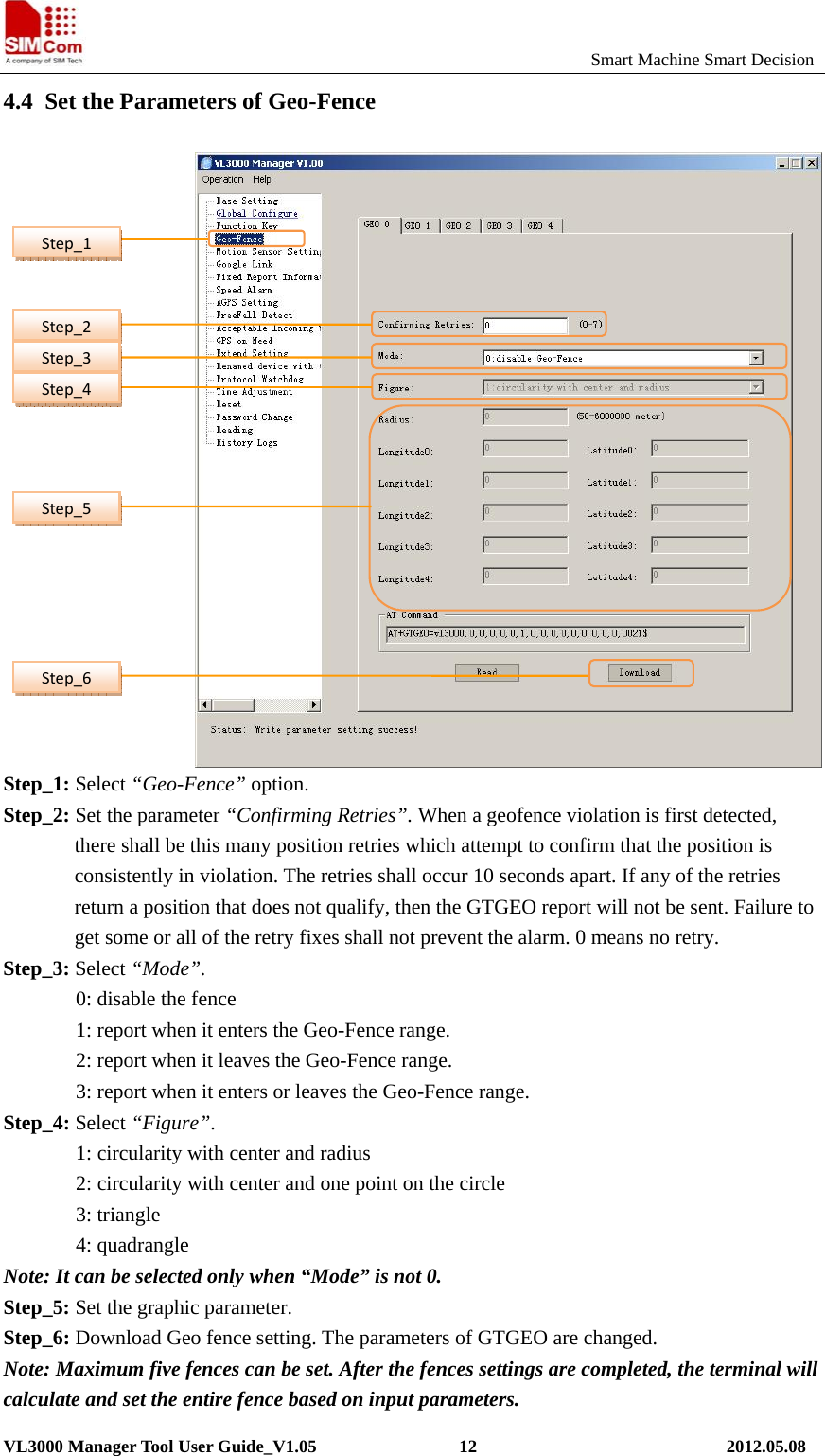
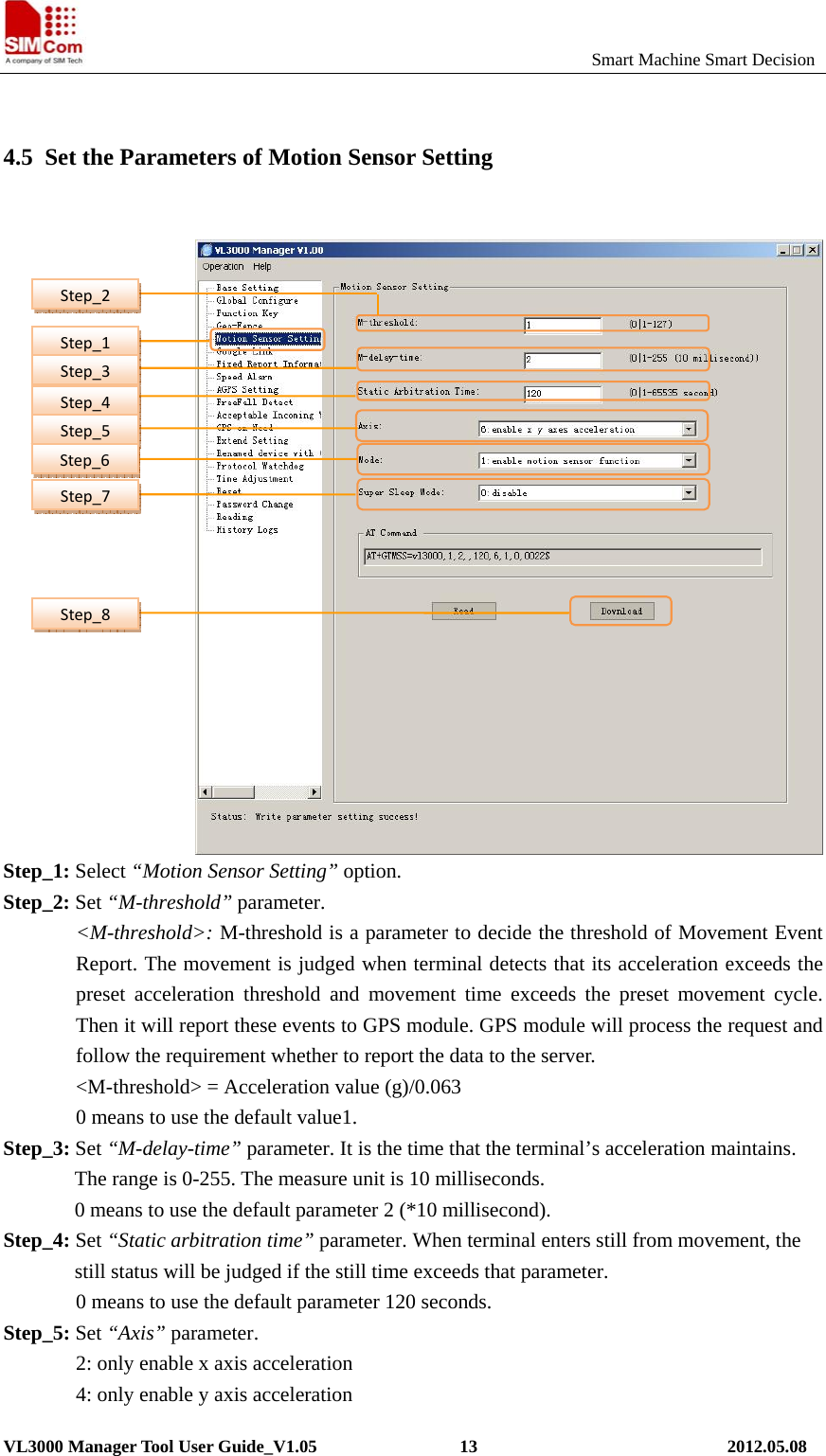
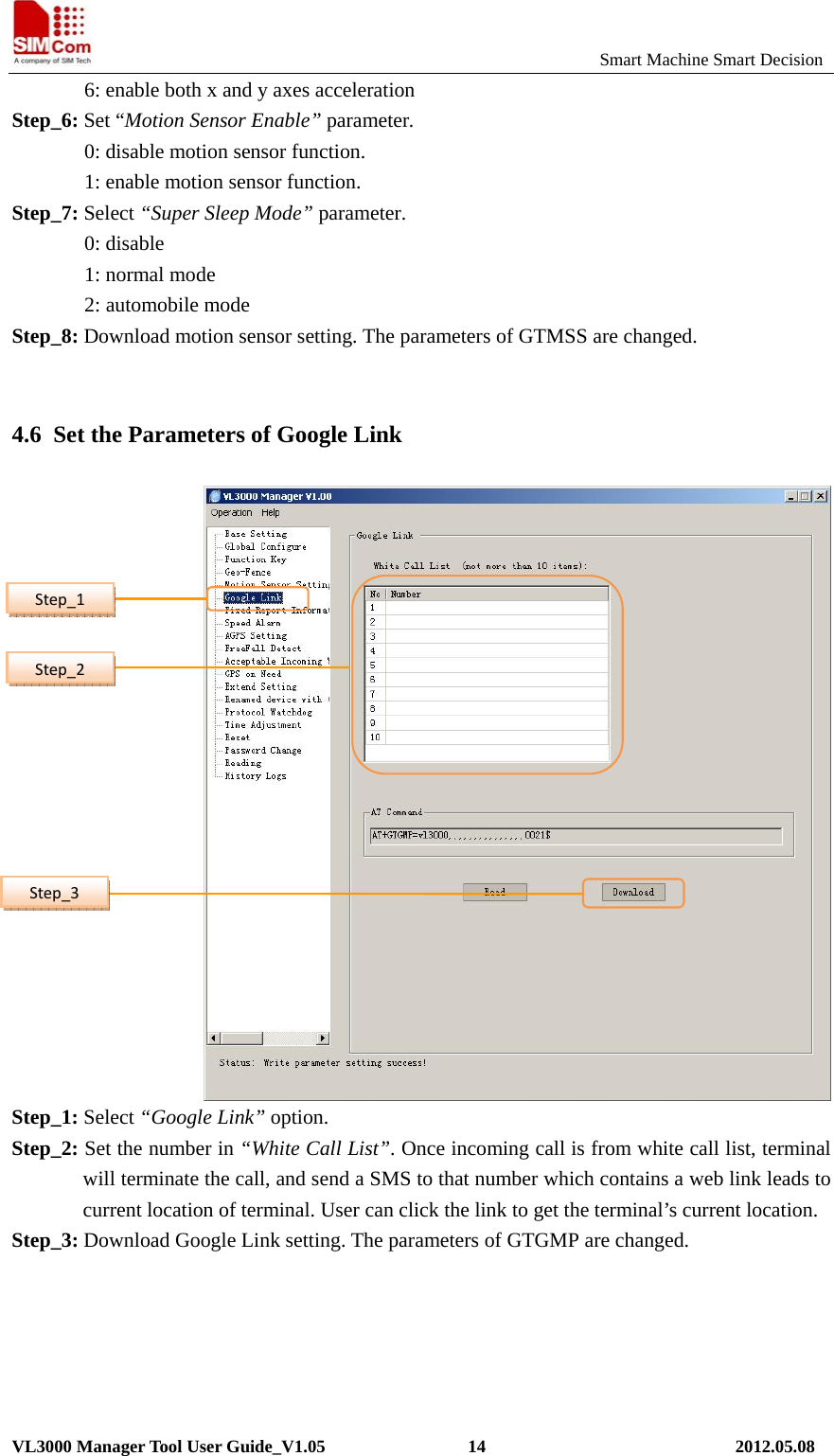
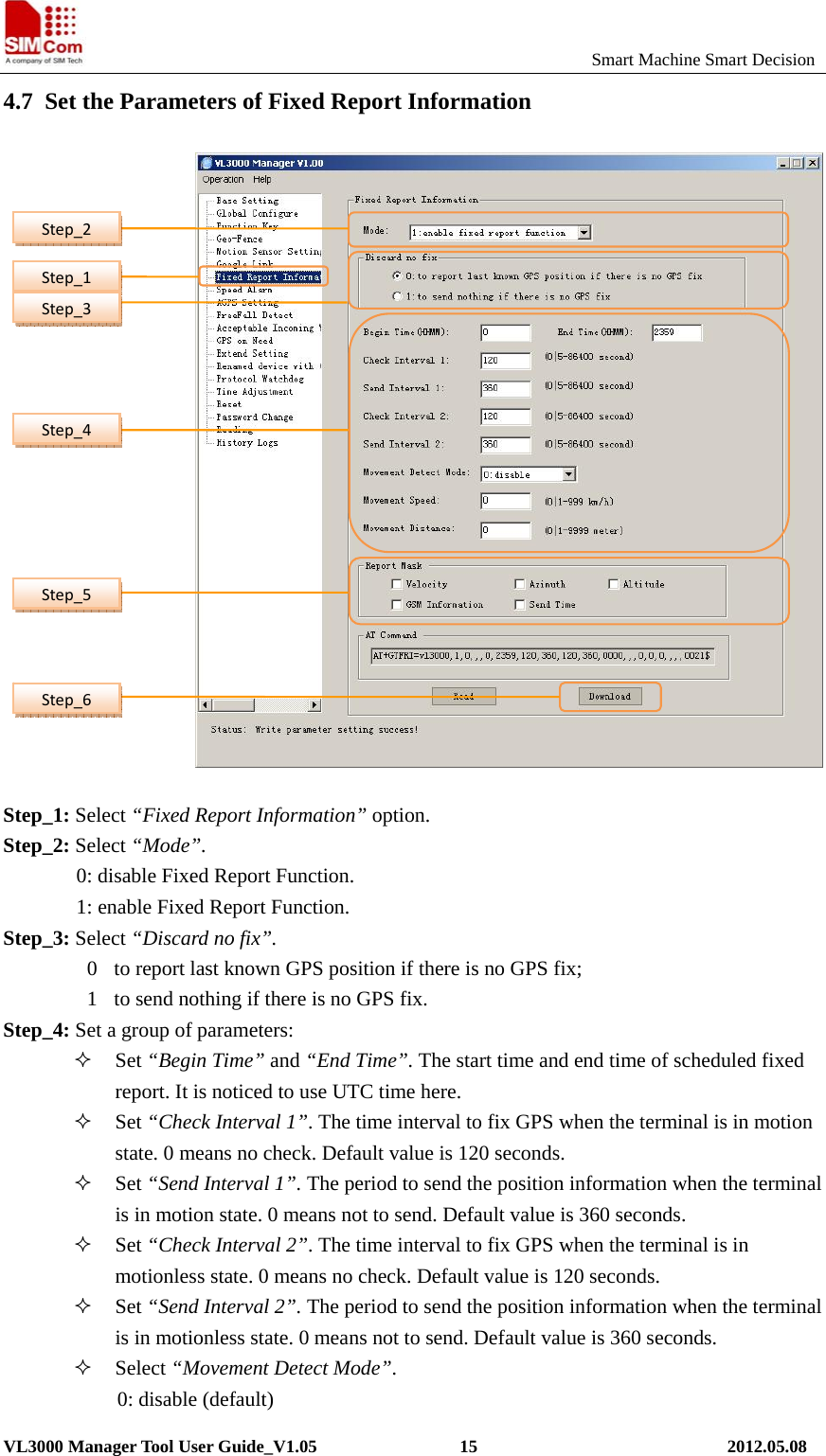
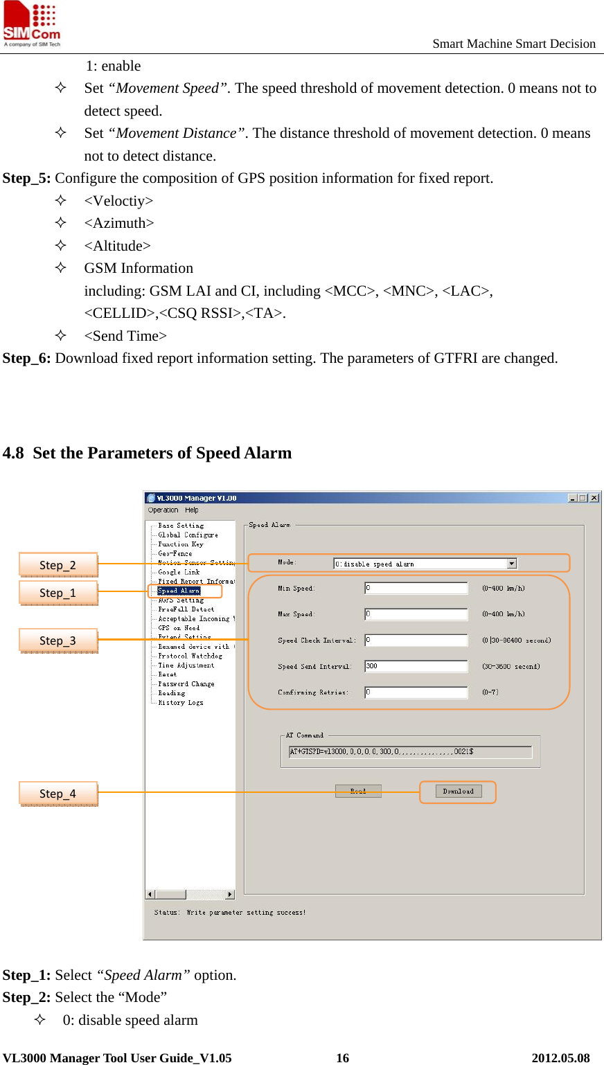
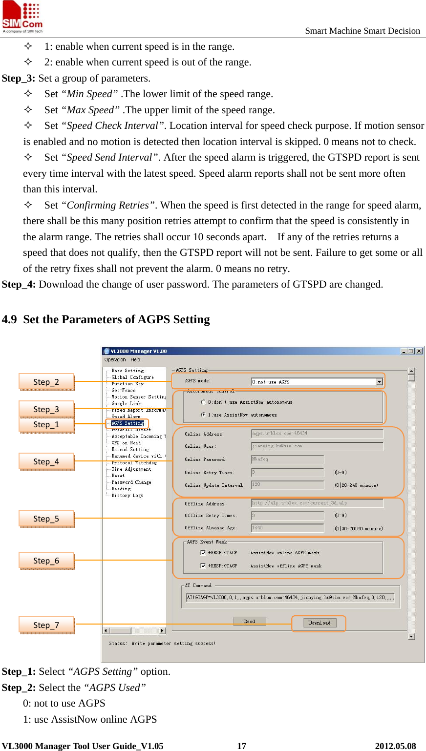
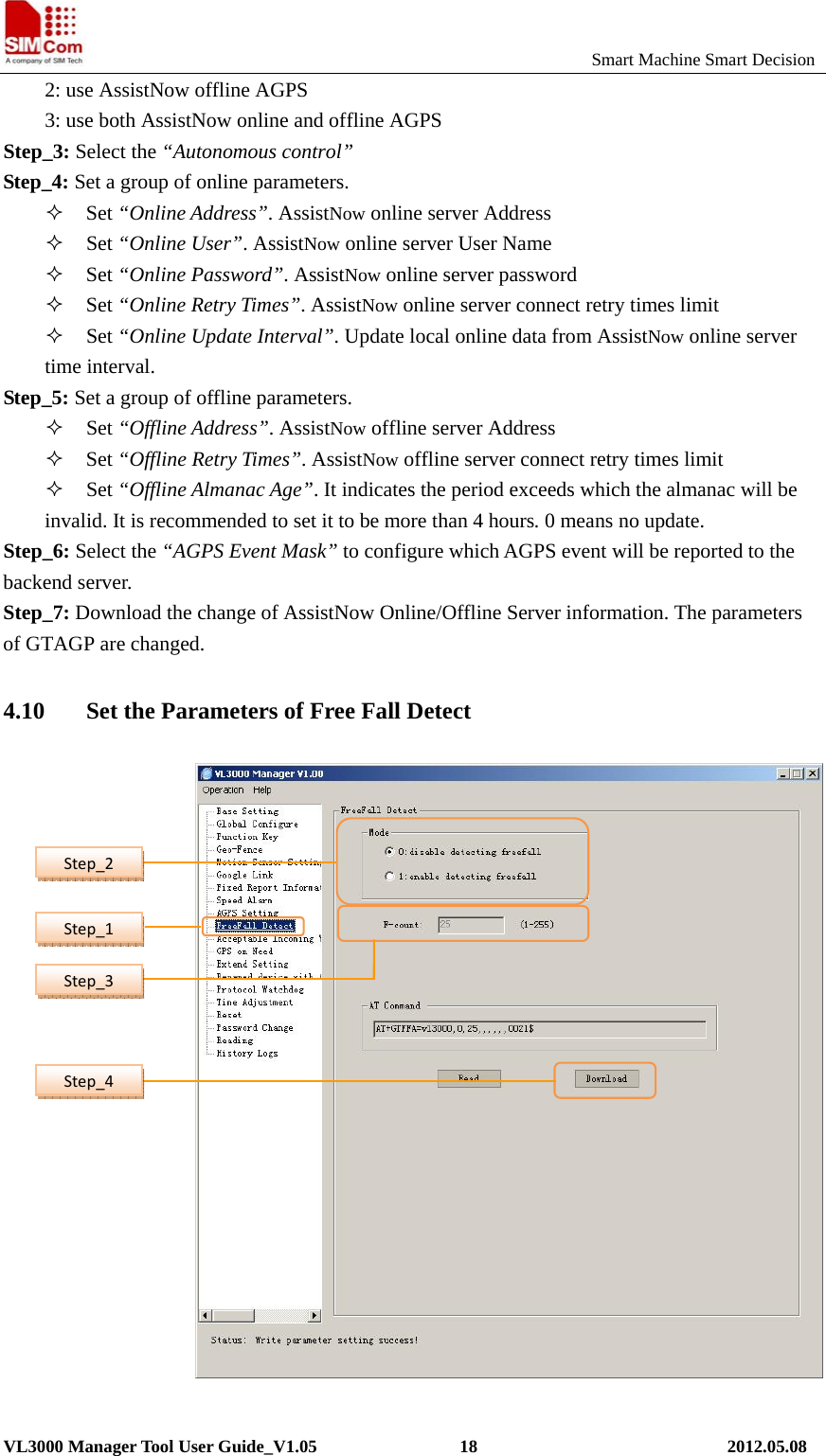
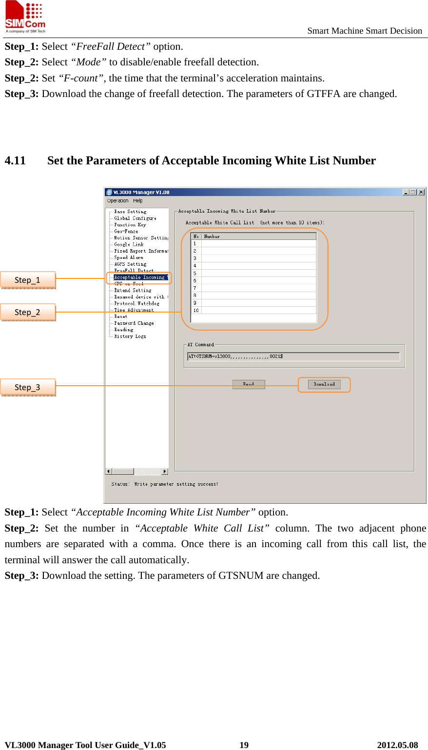
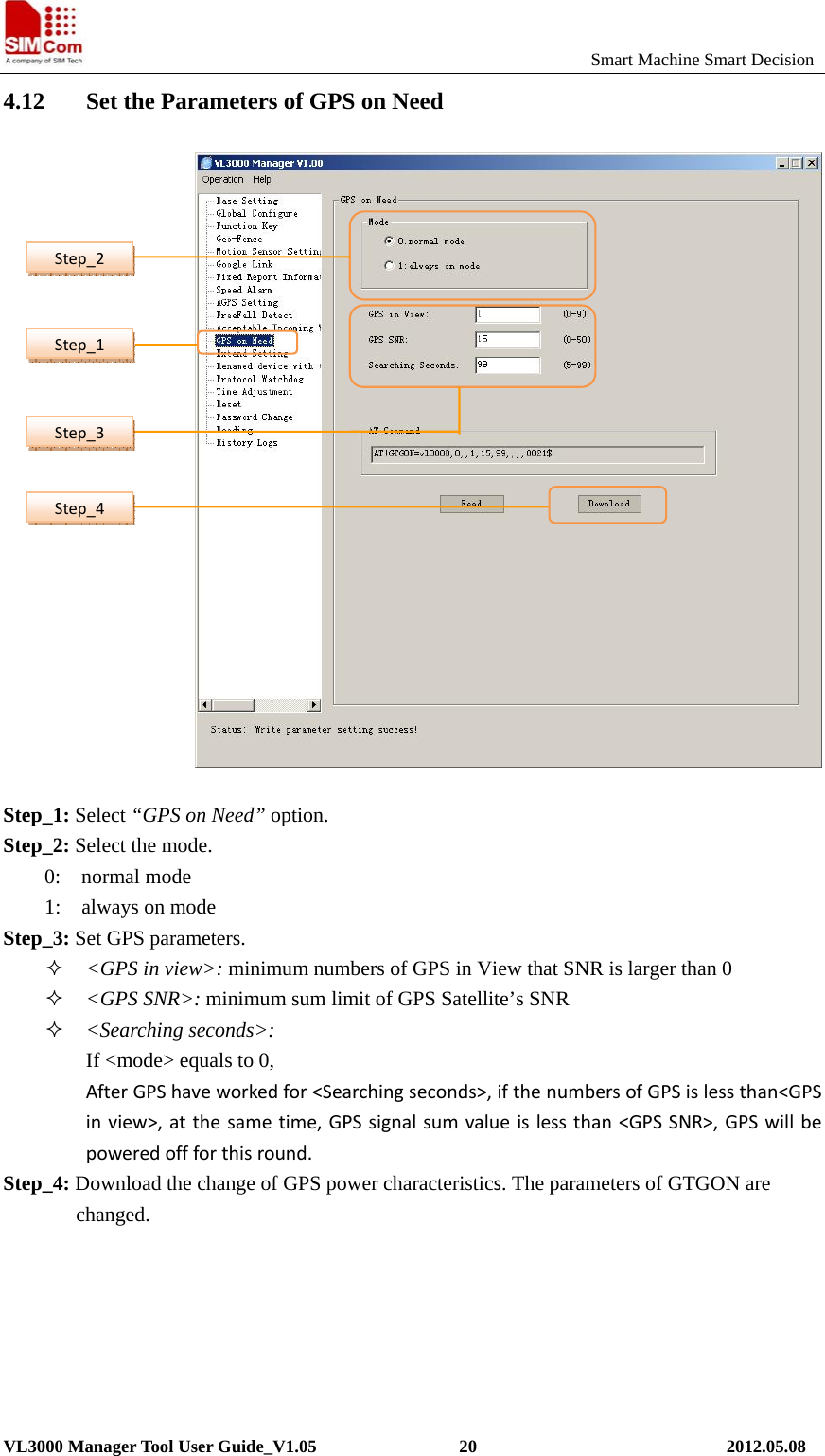
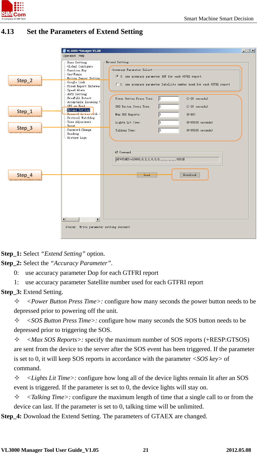
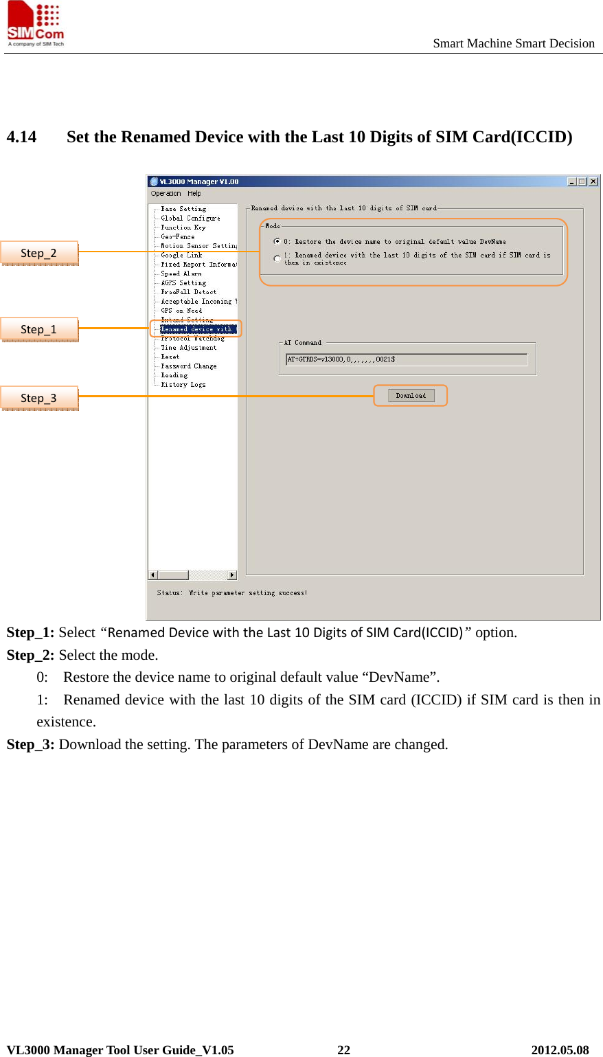
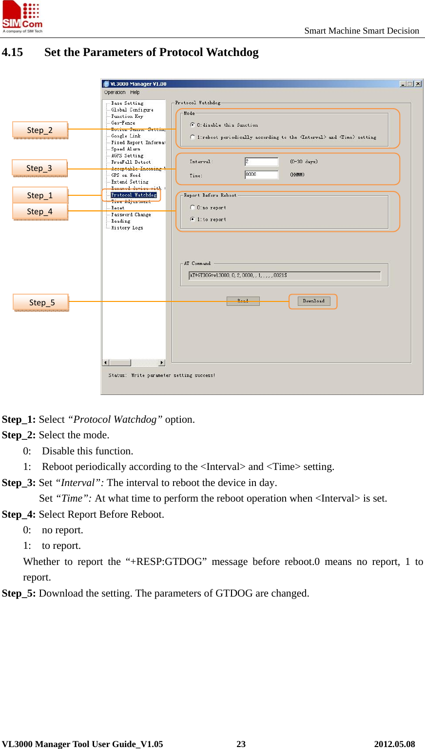
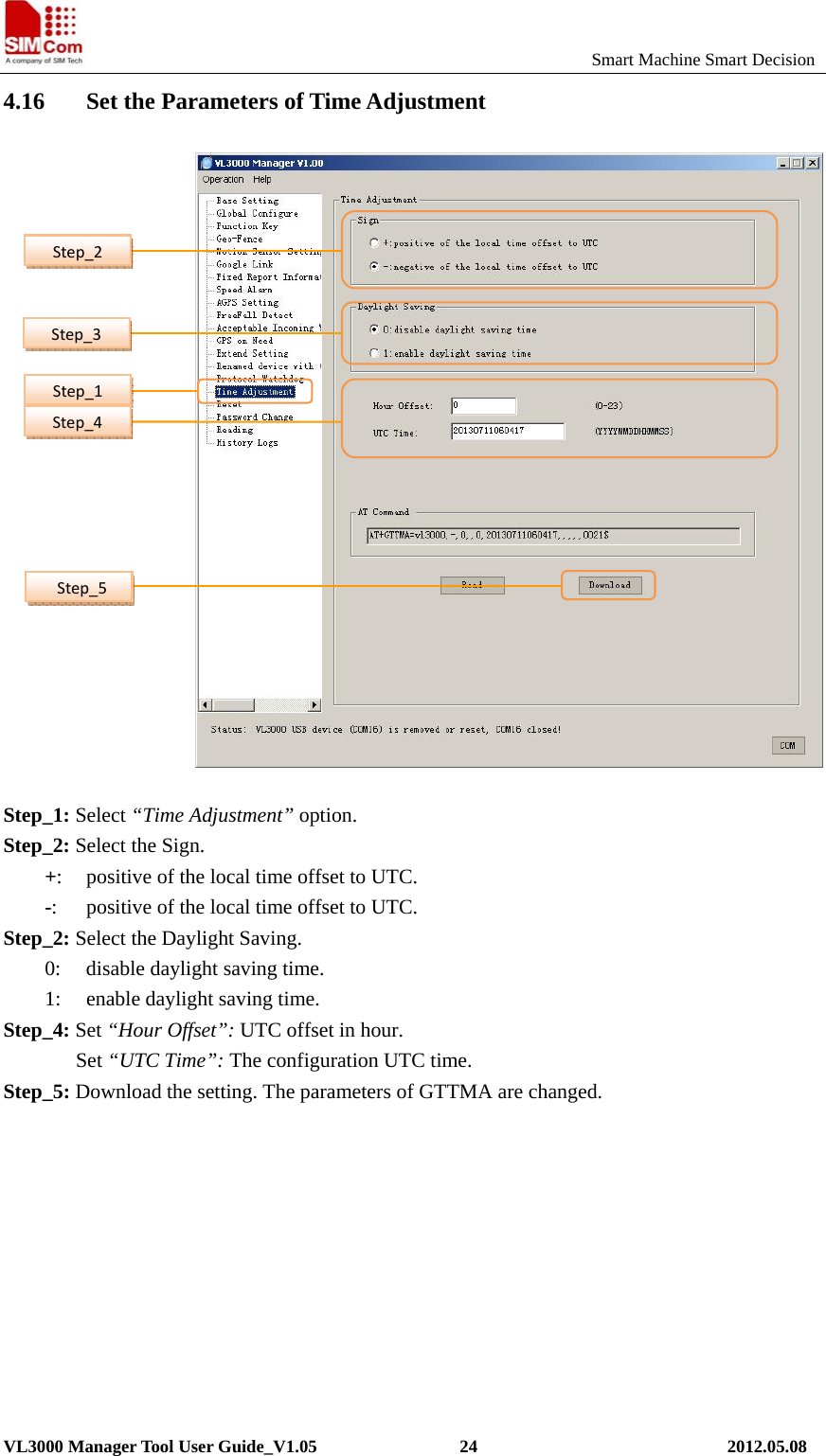
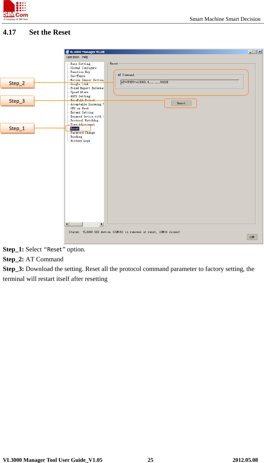
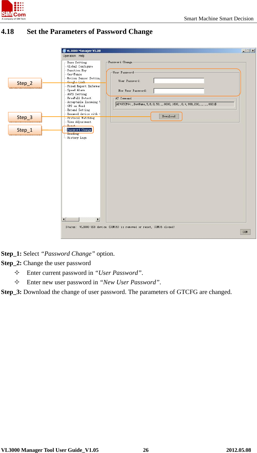
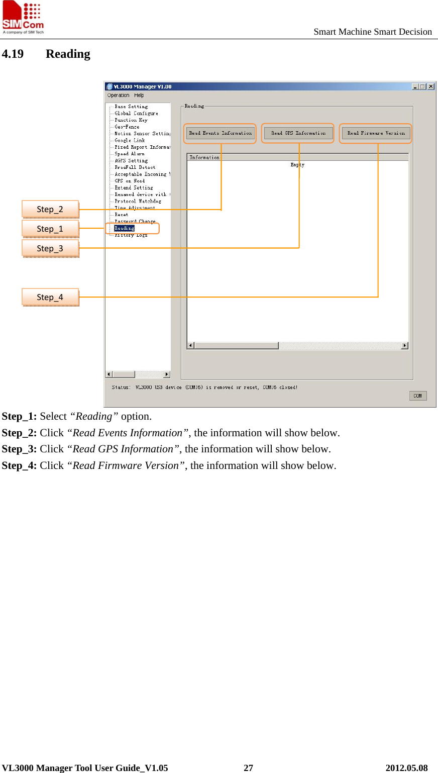
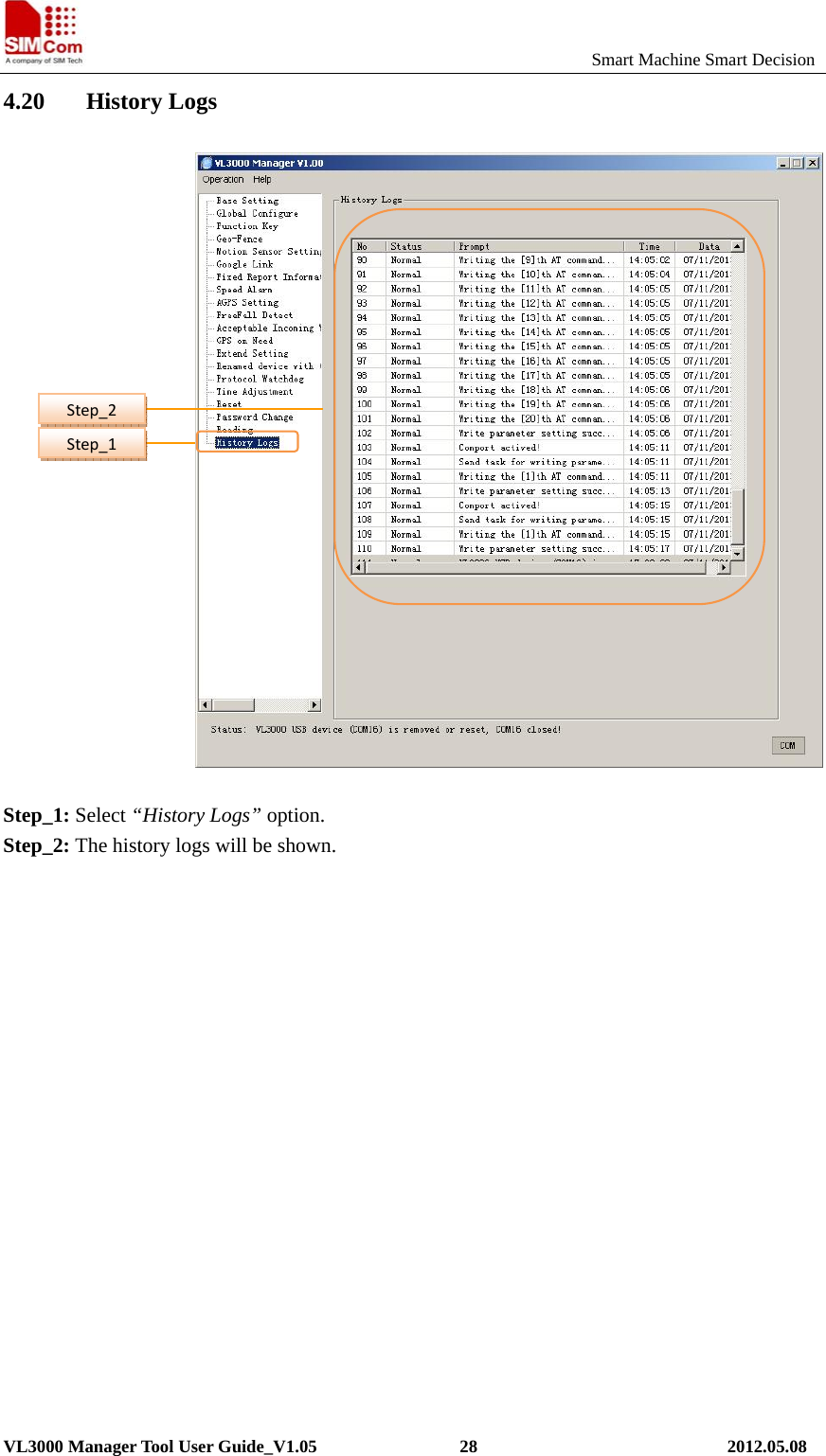
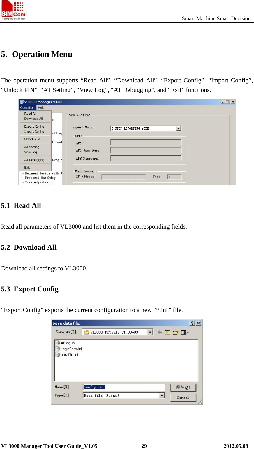
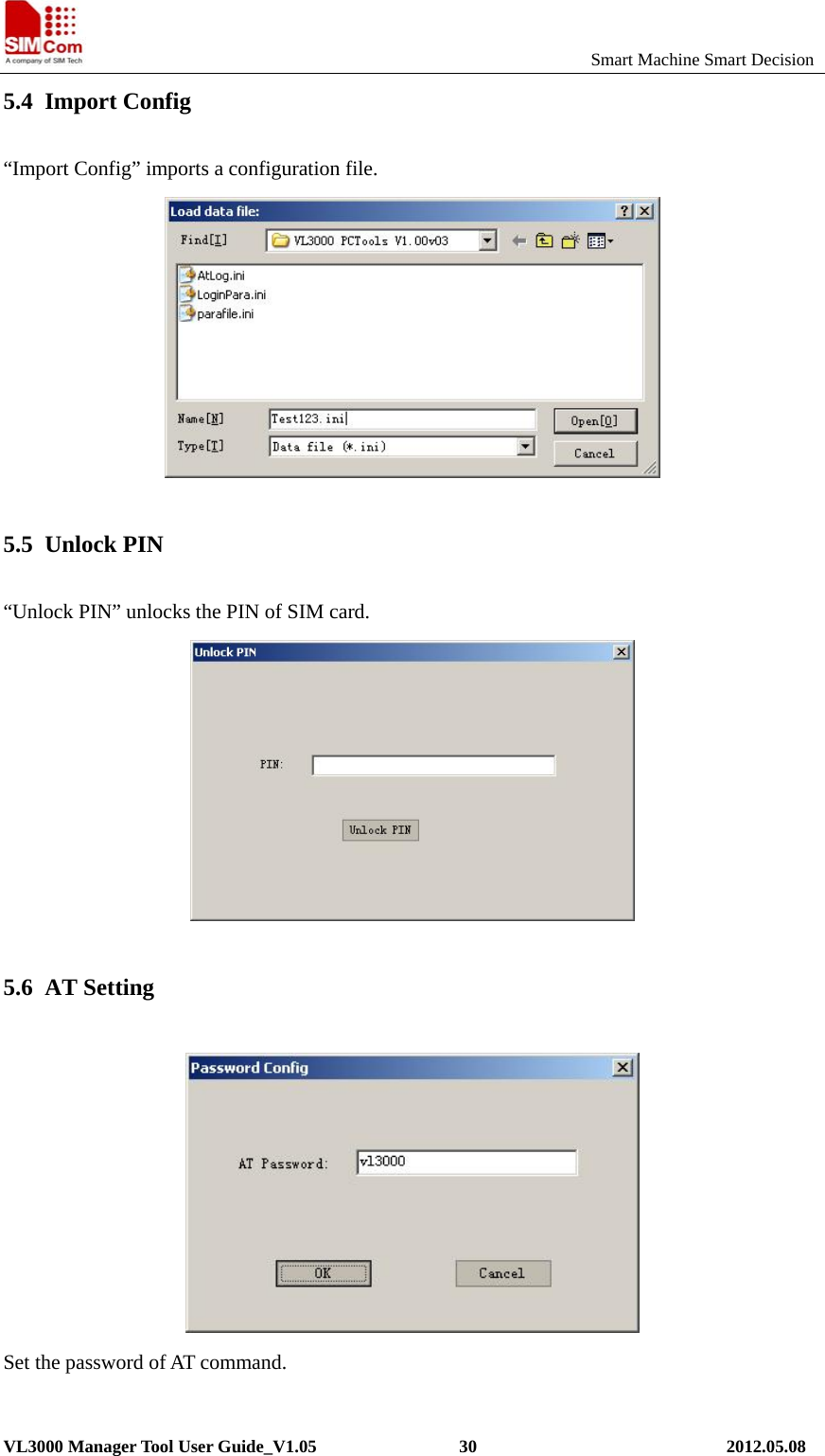
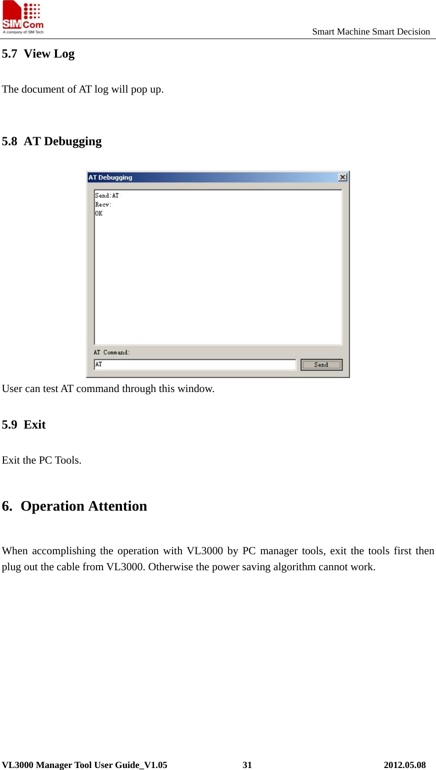
![Smart Machine Smart DecisionVL3000 Manager Tool User Guide_V1.05 7 2012.05.08 ¾ Function setting The function setting zone is used to set and view the parameters of the function. ¾ AT Command This column shows the command message which will be sent to the terminal. The command message can also be sent to the terminal through SMS or GPRS. Note: The last parameter of “AT command” (the parameter before ‘$’ character) is the sequence number for command. It will be invoked in the ACK message of the command. ¾ Operations [Read]: Import the setting from the local configuration. [Download]: Download the settings to the terminal via AT command. ¾ Status Display the status of operation, including the serial port status.](https://usermanual.wiki/Micron-Electronics/0508201300001/User-Guide-2058702-Page-7.png)