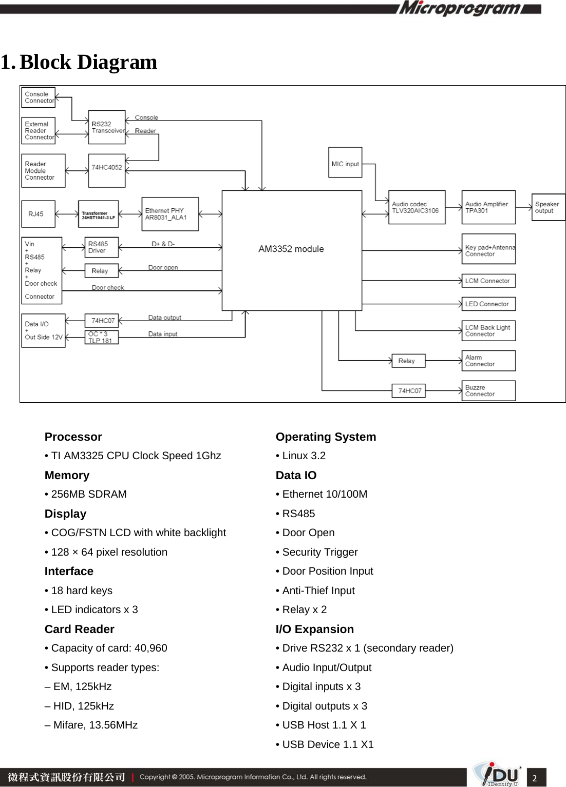
Microprogram Information MP180L RFID Reader User Manual MP180L 1 x
Microprogram Information Co., Ltd. RFID Reader MP180L 1 x
UserManual.wiki
>
Microprogram Information
>
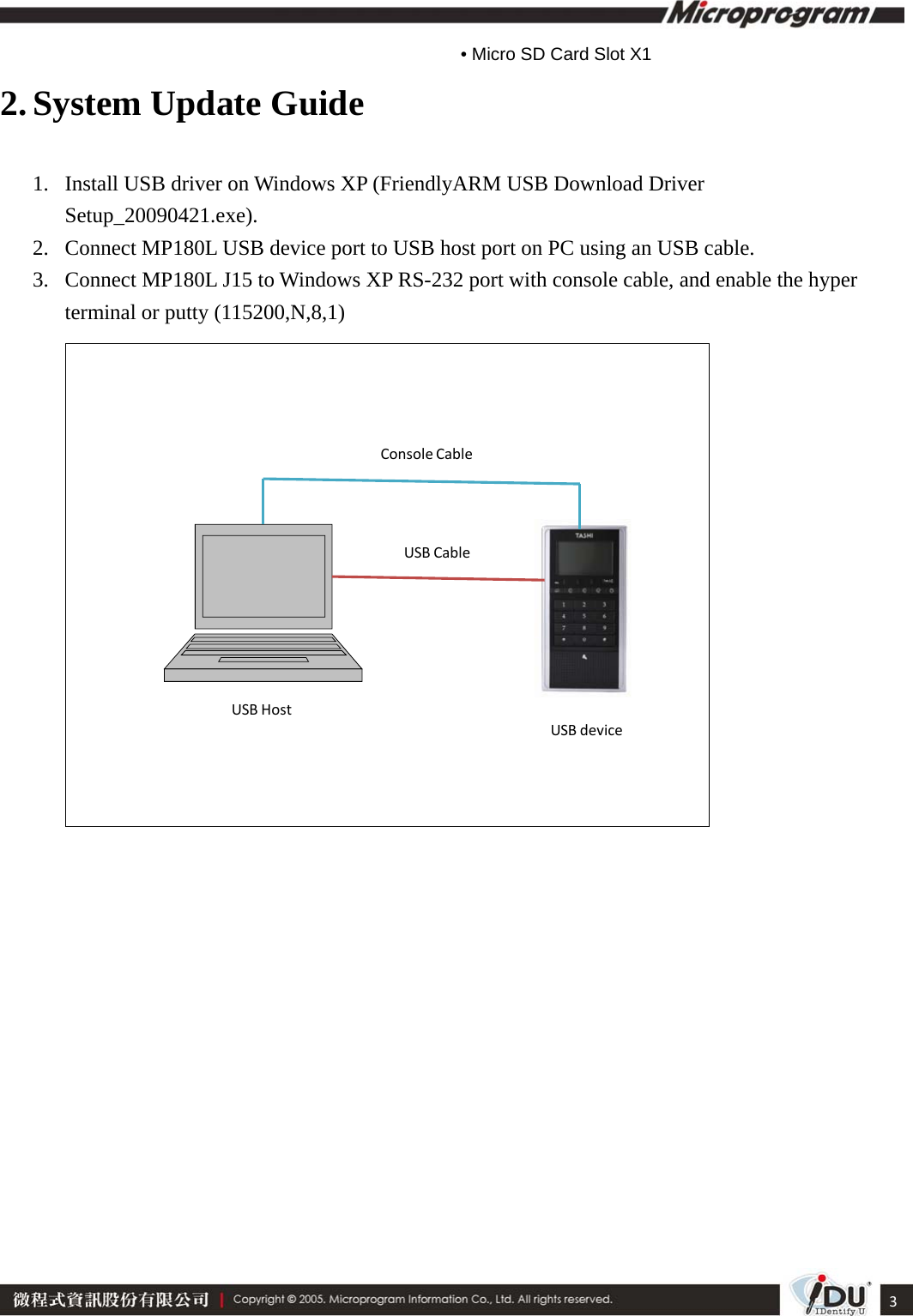
MP180L User Manual
Users Manual
Navigation menu
Upload a User Manual
Namespaces
Wiki Guide
HTML
PDF
Info
Views
User Manual
Discussion / Help
Navigation
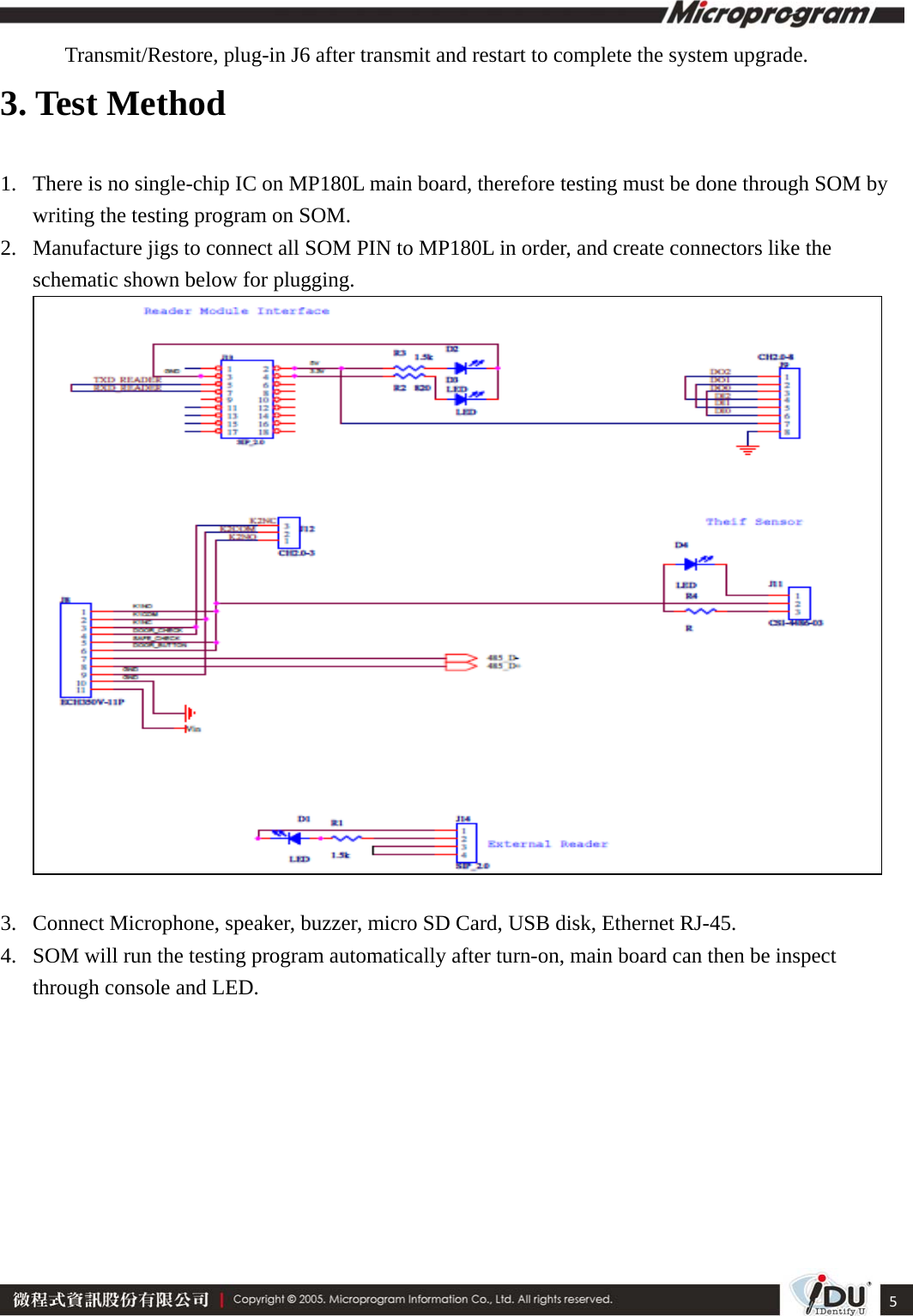
![4 4. Remove J6 Jumper and turn on MP180L, it will then enter SOM BIOS setup menu. 5. Run download tool DNW.exe. 6. Select [ r ] Restore NAND Flash from HOST through USB in terminal or putty. 7. Access download tool DNW and select the latest system backup in USB Port ->](https://usermanual.wiki/Microprogram-Information/MP180L/User-Guide-2644675-Page-5.png)