Dark Field Series Illuminator Configuration Guide Darkfieldconfigguide
2011-08-08
: Microscan Darkfieldconfigguide darkfieldconfigguide 13b8e8d0-adb7-4ac6-9c89-4f5a1681a888 _att
Open the PDF directly: View PDF ![]() .
.
Page Count: 2
Copyright ©2010 Microscan Systems, Inc. P/N 83-230003 Rev B
Nerlite Dark Field Light Series Illuminators
Conguration Guide
Strobe Current Continuous Operation Strobe Operation
No Controller Required NL-2XX Optional Connection Notes Reference Number
Part Ring 1 (& 2 (Can be Connected (Used only if Intensity And/Or Ethernet (See the Connection
Number Description Continuous Current Where Applicable) Ring 3 Fan Cooled Directly to 24VDC) Control Is Desired) NL-2XX (Required) Notes on back of the Page)
NER-011609311 DF-50 Red Continuous, Non-Diffuse 69mA NA NA Figure A Figure B 1
NER-011609312 DF-50 Red Strobe, Non-Diffuse NA 1.20A NA Figure B 1
NER-011609321 DF-50 White Continuous, Non-Diffuse 120mA NA NA Figure A Figure B 1
NER-011609322 DF-50 White Strobe, Non-Diffuse NA 2.40A NA Figure B 1
NER-011609331 DF-50 Blue Continuous, Non-Diffuse 120mA NA NA Figure A Figure B 1
NER-011609332 DF-50 Blue Strobe, Non-Diffuse NA 2.40A NA Figure B 1
NER-011601520 DF-100-1 Red Continuous, Non-Diffuse 100mA NA NA Figure A Figure B 1
NER-011601521 DF-100-1 Red Continuous, Diffuse 100mA NA NA Figure A Figure B 1
NER-011601502 DF-100-1 Red Strobe, Diffuse NA 2.00A NA Figure B 1
NER-011600020 DF-150-1 Red Continuous, Non-Diffuse 100mA NA NA Figure A Figure B 1
NER-011600004 DF-150-1 Red Strobe, Non-Diffuse NA 2.00A NA Figure B 1
NER-011600031 DF-150-1 White Continuous, Non-Diffuse 196mA NA NA Figure A Figure B 1
NER-011600032 DF-150-1 White Strobe, Non-Diffuse NA 4.00A NA Figure B 1
NER-011600070 DF-150-1 Blue Continuous, Non-Diffuse 196mA NA NA Figure A Figure B 1
NER-011600080 DF-150-1 Blue Strobe, Non-Diffuse NA 4.00A NA Figure B 1
NER-011600021 DF-150-1 Red Continuous, Diffuse 100mA NA NA Figure A Figure B 1
NER-011600007 DF-150-1 Red Strobe, Diffuse NA 2.00A NA Figure B 1
NER-011600041 DF-150-1 White Continuous, Diffuse 196mA NA NA Figure A Figure B 1
NER-011600042 DF-150-1 White Strobe, Diffuse NA 4.00A NA Figure B 1
NER-011600208 DF-150-3 Red Continuous, Non-Diffuse 300mA NA NA Figure A Figure B 1
NER-011600209 DF-150-3 Red Strobe, Non-Diffuse NA 7.14A NA Figure B 1
NER-011600206 DF-150-3 White Continuous, Non-Diffuse 450mA NA NA Figure A Figure B 1
NER-011600207 DF-150-3 White Strobe, Non-Diffuse NA 8.00A 4.00A Figure B 6
NER-011603300 DF-200-1 Red Continuous, Diffuse 200mA NA NA Figure A Figure B 1
NER-011603301 DF-200-1 Red Strobe, Diffuse NA 4.00A NA Figure B 1
Hardware Required
Item Description Part Number
1 DF Series Illuminators NER-01160XXXX
2 Power Supply DSP60 24VDC 2.5A DIN Mount NER-011504100
3 NL-200 Current Controller Series 98-000152-0X
-
POWER
+ INPUT
-
12V. 1.4A (UNFUSED)
+ POWER OUTPUT
2 2
3
1
1
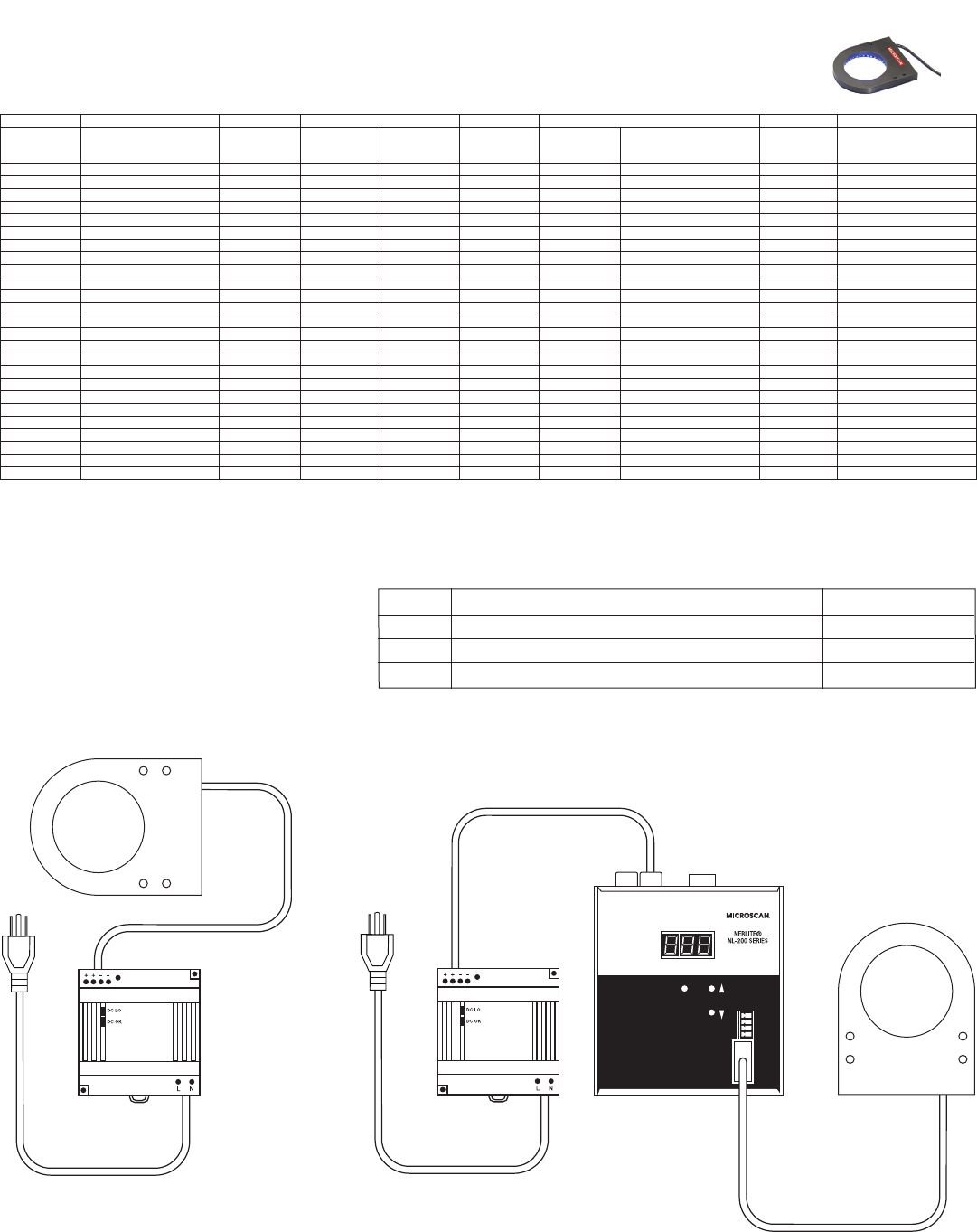
Figure A
Dark Field Series Illuminator
with power supply
Figure B
Dark Field Series Illuminator
with NL-200 and power supply
General Notes:
1. Those lights that do not require a controller require 24VDC +/- 1%.
2. The NL-2XX series controllers require 24 to 48VDC.
3.Thecableonallyingleadmodelsisterminatedwiththree,ve,orsevenleads.Eachleadislabeled.See“ConnectionNotes”forconnectioninstructions.
4.ForallmodelswithM12connectors,theconnectorisa4pin,male,M12connector.See“ConnectionNotes”orconnectorpinoutandconnectioninstructions.
5.Allmodelswithseparatefancircuitsmusthave24VDCconnectedtothefancircuitatalltimeswhenthelightisoperating.
6. When operating in strobe mode at the maximum rated current, the maximum pulse width = 1mS and the maximum duty cycle = 6%. See the NL-2XX series controllers’
manualforpulsewidthanddutycyclelimitationsundervariousconditions.
7.ATTENTION!WhenprogramminganNL-2XXseriescontrollerforuseinstrobemode,youmustsetthecurrentratingto10%ofthecurrentspeciedinthisconguration
guide.InthefewcaseswhereanindividuallightthatrequiresbothchannelsoftheNL-200,besuretosetthecurrentforeachchannelasspeciedinthisconguration
guided. Note: The currents for channel 1 and channel 2 are not always the same. The NL-2XX Series Controller allows the operator to set the output to 1000% of the rated
currentinstrobemode.Byprogrammingtheinitialcurrentratingat10%ofthelight’sratedcurrent,fullintensityisachievedandthecontrollerispreventedfromexceeding
thelight’sratedcurrent.Settingthecurrentratingatavaluegreaterthan10%ofthecurrentprintedonthecongurationlabelonthelightmayresultindamagetothelight.
Connection Notes:
1.Connecttheleadlabeled“V+”tothepositive(+)outputterminalofthepowersupplyorcontroller.Connecttheleadlabeled“GND”tothenegative(-)outputterminalofthe
powersupplyorcontroller.Connecttheleadlabeled“Shield”or“SHLD”tochassisground.
2.Connecttheleadlabeled“V+”tothepositive(+)outputterminalofthepowersupplyorcontroller.Connecttheleadlabeled“GND”tothenegative(-)outputterminalofthe
powersupplyorcontroller.Connecttheleadlabeled“FanV+”tothepositive(+)outputterminalofa24VDCpowersupply.Connecttheleadlabeled“FanGND”tothenega-
tive(-)outputterminalofa24VDCpowersupply.Connecttheleadlabeled“Shield”tochassisground.
3.Connecttheleadlabeled“V+1”tothepositive(+)outputterminalofchannel1onanNL-2XXseriescontroller.Connecttheleadlabeled“GND1”tothenegative(-)output
terminalofchannel1ontheNL-2XXseriescontroller.Connecttheleadlabeled“V+2”tothepositive(+)outptterminalofchannel2ontheNL-2XXseriescontroller.Connect
theleadlabeled“GND2”tothenegative(-)outputterminalofchannel2ontheNL-2XXseriescontroller.Connecttheleadlabeled“Shield”tochassisground
4.Connecttheleadlabeled“+”tothepositive(+)outputterminalofthepowersupplyorcontroller.Connecttheleadlabeled“-”tothenegative(-)outputterminalofthepower
supply or controller. Connect the cable’s braided shield to chassis ground.
5.Connecttheleadlabeled“DOALV+”tothepositive(+)outputterminalofchannel1onanNL-2XXseriescontroller.Connecttheleadlabeled“DOALGND”tothenega-
tive(-)outputterminalofchannel1ontheNL-2XXseriescontroller.Connecttheleadlabeled“RingV+”tothepositive(+)outputterminalofchannel2ontheNL-2XXseries
controller.Connecttheleadlabeled“RingGND”tothenegative(-)outputterminalofchannel2ontheNL-2XXseriescontroller.Connecttheleadlabeled“FanV+”tothe
positive(+)outputterminalofa24VDCpowersupply.Connecttheleadlabeled“FanGND”tothenegative(-)outputterminalofa24VDCpowersupply.Connectthelead
labeled“Shield”tochassisground.
6.Connectthetwoleadslabeled“RING1,2V+”&“RING3V+”tothesamepositive(+)outputterminalofthepowersupplyorcontroller.Connectthetwoleadslabeled“RING
1,2-”&“RING3-”tothesamenegative(-)outputterminalofthepowersupplyorcontroller.Connecttheleadlabeled“Shield”tochassisground.
7.ConnectPin1oftheM12-Mconnectortothepositive(+)outputterminalofthepowersupplyorcontroller.ConnectPin3oftheM12-Mconnectortothenegative(-)output
terminal of the power supply or controller. Connect the shell of the M12-M connector to chassis ground. Pins 2 and 4 are not used.
NERLITE Dark Field Light Series Illuminators
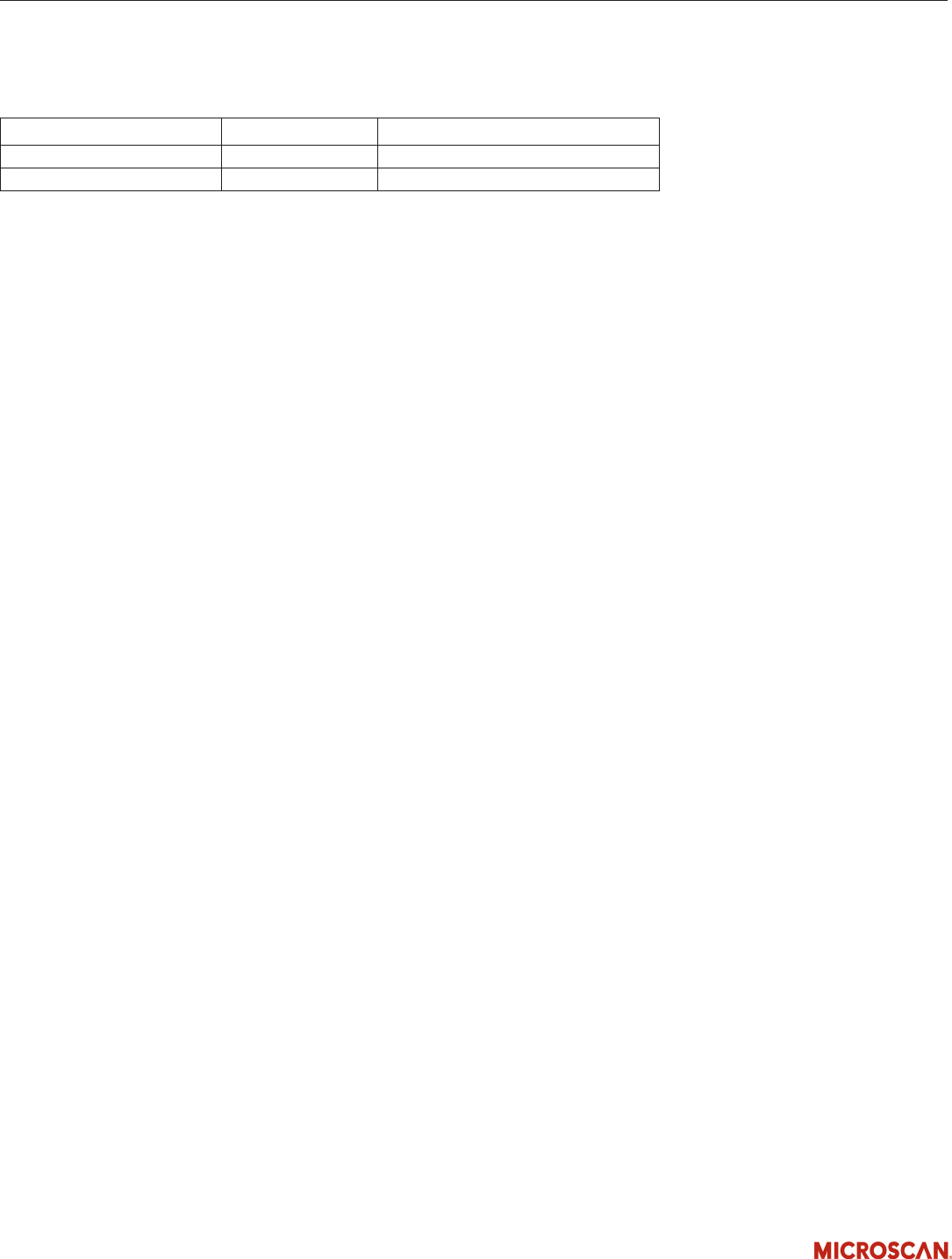
Accessories
AC Power Cord US NER-030028300 Power Cord For Power Supply
AC Power Cord EU NER-030028400 Power Cord For Power Supply
AC Power Cord UK NER-030028500 Power Cord For Power Supply
Copyright ©2010 Microscan Systems, Inc. www.microscan.com
